Embed Size (px)
Citation preview

Progress In Electromagnetics Research Letters, Vol. 21, 129–137, 2011
A NEW DUAL-POLARIZED HORN ANTENNA EXCITEDBY A GAP-FED SQUARE PATCH
S. Ononchimeg, G. Otgonbaatar, J.-H. Bang, and B.-C. Ahn
Applied Electromagnetics LaboratoryDepartment of Radio and Communication EngineeringChungbuk University, Cheongju 361-763, Korea
E.-J. Cha
Department of MedicineChungbuk University, Cheongju 361-763, Korea
Abstract—A new dual-polarized horn antenna fed by a microstrippatch is proposed. The patch is excited in two orthogonal polarizationsby small gaps between the patch edge and the microstrip open end.A horn antenna operating at 14.9GHz is designed, fabricated andtested. Measurements show that the horn has a reflection coefficient ofless than −10 dB, and a port isolation greater than 30 dB, over 14.6–15.2GHz, and a gain of 12.34 dBi and 10-dB beamwidths of 87◦ and88◦ at 14.9GHz.
1. INTRODUCTION
Dual-polarized antennas are used in such diverse applications asradio astronomy, radar polarimetry, frequency-reuse and polarization-diversity communications, and antenna measurements [1, 2]. Dual-polarized antennas can be realized by exciting two linearly polarizedwaves whose electric field vectors are at 90 degrees to each other or bysimultaneously utilizing right- and left-hand circularly polarized.
Dual-polarized horn antennas have been traditionally realizedby feeding the input square waveguide with two orthogonal coaxialprobes [3]. In some applications, it is favorable to excite a hornwith a printed-circuit structure. In this case, a transition betweenthe coaxial cable and the printed-circuit transmission line can beeliminated, making it easy to integrate the horn with printed circuits.
Received 26 January 2011, Accepted 28 February 2011, Scheduled 8 March 2011Corresponding author: Sodnomtseren Ononchimeg ([email protected]).

130 Ononchimeg et al.
There have been some research results on horn antennas excitedby printed circuit structures such as the microstrip probe, dipole andpatch antennas [4, 5]. Dual-polarized horn antennas fed by printedcircuit elements have been studied in [6–8]. In existing results [6–8],the port isolation is not high due to a strong mutual coupling betweenfeeding elements.
In this paper, we propose a new compact dual-polarized hornantenna with high port isolation. A square patch antenna is excitedat two orthogonal edges by coupling through a small gap betweenthe patch edge and the microstrip open end. The patch launchestwo orthogonal and linear polarized waves in the square waveguideof the horn. The dual-polarized horn proposed in this paper hasa narrow bandwidth due to the use of a microstrip patch in thefeeding circuit so that it is suitable for narrow-band applications. Theproposed antenna is analyzed and optimized using the widely-usedelectromagnetic simulation software Microwave StudioTM by CST. Thedesigned antenna is fabricated and its performance is measured andcompared with the simulation.
2. ANTENNA DESIGN
Figure 1 shows the structure of the proposed horn antenna. Thehorn consists of two microstrip lines, a gap-fed dual-polarized patch, asquare waveguide and a pyramidal horn.
Open ends of two microstrip lines excite orthogonal currents on thepatch by the capacitive coupling through a small gap at the patch edge.The patch launches TE10 and TE01 fundamental modes in the squarewaveguide. Walls of the square waveguide are electrically connected tothe ground plane of the circuit board via closely-spaced through holes.The horn and the circuit board are joined together with a silver-epoxyconductive adhesive. Small screws can also be used for the assembly.
The horn antenna is designed in three steps. First, we designa pyramidal horn antenna with specified characteristics. Next, wedesign a dual gap-fed rectangular patch. Finally, we combine thepatch and the horn, and adjust relevant dimensions for good impedancematching. Design requirements of the proposed antenna call for thecenter frequency of 14.9GHz with impedance bandwidth of 200 MHzand 10-dB beamwidths of 87◦ in both E- and H-planes. The antenna isto be used as a feed in a dual-polarized reflector antenna for terrestrialpoint-to-point communications.
Figure 2 shows a pyramidal horn antenna with a square inputwaveguide. The width and height of the square waveguide are chosen tobe same as the broad wall width (15.75mm) of a standard rectangular

Progress In Electromagnetics Research Letters, Vol. 21, 2011 131
Horn
Waveguide
Slot
Ground plane
Radiating Patch
Via hole
Substrate
( δ )r , tanε
Port 1Port 2
Metal strip
Figure 1. Structure of the proposed antenna.
x
zy Horn
Waveguide
wg
lg lh
t
wh
t
tt
t
wh
wh
wg
wg
x
yz
Figure 2. Structure of a horn with a square waveguide.
waveguide WR-28. The initial length of the square waveguide is chosento be lg = λ0/2, which is a half wavelength at 14.9 GHz. The squarewaveguide length has an effect on the reflection coefficient, which isminimum when lg is around λ0/2. For the pyramidal section we chooseinitial dimensions such that wh = 2wg and lh = λ0/2. The lengthand aperture size of the horn determine the bandwidth. The largerthey are, the smaller the beamwidth will be. For a given beamwidthand the antenna size limitation, one can determine their values bygradually increasing them until the desired beamwidth is obtained. In
132 Ononchimeg et al.
the simulation, the square waveguide is excited with the TE10 modeusing the wave port in Microwave StudioTM software.
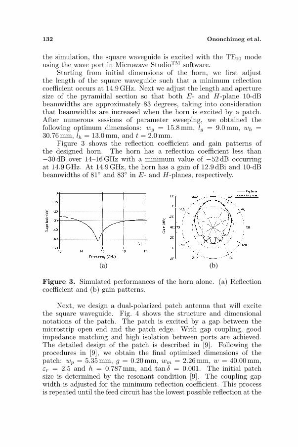
Starting from initial dimensions of the horn, we first adjustthe length of the square waveguide such that a minimum reflectioncoefficient occurs at 14.9GHz. Next we adjust the length and aperturesize of the pyramidal section so that both E- and H-plane 10-dBbeamwidths are approximately 83 degrees, taking into considerationthat beamwidths are increased when the horn is excited by a patch.After numerous sessions of parameter sweeping, we obtained thefollowing optimum dimensions: wg = 15.8 mm, lg = 9.0mm, wh =30.76mm, lh = 13.0 mm, and t = 2.0mm.
Figure 3 shows the reflection coefficient and gain patterns ofthe designed horn. The horn has a reflection coefficient less than−30 dB over 14–16 GHz with a minimum value of −52 dB occurringat 14.9 GHz. At 14.9 GHz, the horn has a gain of 12.9 dBi and 10-dBbeamwidths of 81◦ and 83◦ in E- and H-planes, respectively.
(a) (b)
Figure 3. Simulated performances of the horn alone. (a) Reflectioncoefficient and (b) gain patterns.
Next, we design a dual-polarized patch antenna that will excitethe square waveguide. Fig. 4 shows the structure and dimensionalnotations of the patch. The patch is excited by a gap between themicrostrip open end and the patch edge. With gap coupling, goodimpedance matching and high isolation between ports are achieved.The detailed design of the patch is described in [9]. Following theprocedures in [9], we obtain the final optimized dimensions of thepatch: wp = 5.35mm, g = 0.20mm, wm = 2.26mm, w = 40.00mm,εr = 2.5 and h = 0.787mm, and tan δ = 0.001. The initial patchsize is determined by the resonant condition [9]. The coupling gapwidth is adjusted for the minimum reflection coefficient. This processis repeated until the feed circuit has the lowest possible reflection at the

Progress In Electromagnetics Research Letters, Vol. 21, 2011 133
w
wp
g
h
Radiating
Patch
Substrate
( δ )
Ground
plane
Port1
Port2wp
wm
w
wm
g
r , tanε
x
yz
z
yx
Figure 4. Dual-polarized patch fed by gap coupling.
Figure 5. Simulated reflection coefficient and port isolation of thepatch.
center frequency. Fig. 5 shows the performance of the designed patch.At 14.9GHz, the patch has a reflection coefficient of −26 dB and aport isolation of 29 dB. The impedance bandwidth (−10 dB reflection)is 4.3% (644MHz) and the antenna gain is 6.7 dBi.
Finally the patch is installed inside the square waveguide in amanner shown in Fig. 1. A rectangular metal strip is printed aroundthe patch. Closely spaced via holes on the strip connect the waveguidewall to the substrate’s ground plane. Microstrip lines feeding the patch
134 Ononchimeg et al.
enter the square waveguide through small slots in the waveguide wallas shown in Fig. 1.
After assembly, the reflection coefficient of the entire antennastructure is computed. Only the length of the square waveguide,the width and height of the slot are adjusted to obtain an optimumreflection coefficient. The horn antenna of final design has a squarewaveguide length of 11.00 mm and slot width and height of 6.00mmand 2.00mm, respectively. All other dimensions of the antenna remainunchanged from those obtained in the design of each part.
3. ANTENNA FABRICATION AND MEASUREMENT
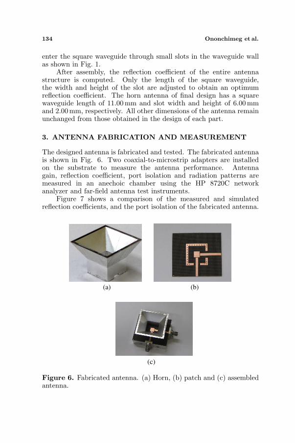
The designed antenna is fabricated and tested. The fabricated antennais shown in Fig. 6. Two coaxial-to-microstrip adapters are installedon the substrate to measure the antenna performance. Antennagain, reflection coefficient, port isolation and radiation patterns aremeasured in an anechoic chamber using the HP 8720C networkanalyzer and far-field antenna test instruments.
Figure 7 shows a comparison of the measured and simulatedreflection coefficients, and the port isolation of the fabricated antenna.
(a) (b)
(c)
Figure 6. Fabricated antenna. (a) Horn, (b) patch and (c) assembledantenna.

Progress In Electromagnetics Research Letters, Vol. 21, 2011 135
Measured results agree well with the simulation. The impedancebandwidth (−10 dB reflection) is 4.1% (600 MHz). The bandwidthof the dual-polarized horn is determined by the microstrip patch ofthe feeding circuit since the horn alone has a much larger bandwidth.The bandwidth of the feeding circuit can be increased by placinganother patch with a slightly different resonant frequency on top ofthe base patch as often done to increase the bandwidth of a microstrippatch [10]. The reflection coefficient of the antenna is less than −10 dBand the port isolation greater than 30 dB over 14.6–15.2 GHz. The portisolation of the assembled antenna is better than that of the patchalone.
Figure 8 shows gain patterns at 14.9 GHz of the fabricatedantenna with port 1 excited and port 2 connected to a matched
Figure 7. Reflection and isolation performances of the fabricated.
(a) (b)
Figure 8. Gain patterns of the fabricated antenna at 14.9 GHz on (a)E- and (b) H-planes.
136 Ononchimeg et al.
load. The proposed antenna’s maximum gain is 12.34 dBi, and its10-dB beamwidths are 87◦ and 88◦ in E- and H-planes, respectively.Measured gain patterns agree well with the simulation in the upperhemisphere, where the maximum error is about 3 dB.
4. CONCLUSION
In this paper, we proposed a new compact dual-polarized horn antennaoperating at Ku-band. Good impedance matching, high port-isolation,and compactness of feeding are achieved by exciting the horn with asquare patch fed by two orthogonal gaps between the microstrip openend and the patch edge. The proposed horn antenna can be easilyintegrated with printed circuits.
The horn antenna and the patch are designed separately andassembled into one structure. Only minor adjustments of dimension arerequired in optimizing the assembled antenna structure. The designedantenna is fabricated and tested. Measurements of the fabricatedantenna show that the proposed antenna has a gain of 12.34 dBi, 10-dB beamwidths of 87◦ and 88◦ in E- and H-planes, respectively, at14.9GHz. The reflection coefficient is less than −10 dB and the portisolation is greater than 30 dB over 14.6–15.2 GHz (600 MHz).
The dual-polarized horn antenna proposed in this paper can beutilized in such applications as feeding a prime focus parabolic dual-polarized reflector antenna and dual-polarized horn arrays where thehorn needs to be easily integrated with printed circuits.
ACKNOWLEDGMENT
This research was supported by the Basic Science Research Programthrough the National Research Foundation of Korea (NRF) funded bythe Ministry of Education, Science and Technology (2011-0001045).
REFERENCES
1. Secmen, M., S. Demir, and A. Hizal, “Dual-polarised T/R antennasystem suitable for FMCW altimeter radar applications,” Proc.IEE Microwave Antennas Propagat. Conf., Vol. 153, 407–412,2006.
2. Lempianien, J. J. A. and J. K. Laiho-Steffens, “The performanceof polarization diversity schemes at a base station in small/microcells at 1800MHz,” IEEE Trans. Vehicular Tech., Vol. 47, No. 3,1087–1092, Aug. 1998.

Progress In Electromagnetics Research Letters, Vol. 21, 2011 137
3. Shen, Z. and F. Chao, “A new dual-polarized broadband hornantenna,” IEEE Antenna Wireless Propagat. Lett., Vol. 4, 270–273, 2005.
4. Sebastian, M. and L.-P. Schmidt, “Design of a balanced-fed patchexcited horn antenna at millimeter-wave frequencies,” Proc. 4thEuropean Conf. Antennas Propagat., 1–4, 2010.
5. Caillet, N., C. Person, C. Quendo, and J. Laskar, “Highgain conical horn antenna integrated to a planar substrate for60GHz WPAN applications,” Proc. 4th European Conf. AntennasPropagat., 5–9, 2010.
6. Seong, N.-S. and S.-O. Park, “A microstrip-fed cavity-backedcircularly polarized horn antenna,” Microw. Opt. Technol. Lett.,Vol. 48, No. 12, 2454–2456, Sep. 2006.
7. Ali-Ahmad, W. Y., C. C. Ling, and G. M. Rebeiz, “Two-dimensional dual-polarized millimeter-wave horn antenna arrays,”Proc. IEEE Antennas Propagat. Int. Symp., Vol. 4, 1429–1432,1990.
8. Yong, Y., L. Yong, and X. Lu, “Dual-polarized antenna based onMEMS technology for terahertz polarimetric radar,” Proc. IETInt. Radar Conf., 1–4, 2009.
9. Ononchimeg, S., J.-H. Bang, B.-C. Ahn, and E.-J. Cha,“A new dual-polarized gap-fed patch antenna,” Progress InElectromagnetics Research C, Vol. 14, 79–87, 2010.
10. Shireen, R., T. Hwang, S. Shi, and D. W. Prather, “Stacked patchexcited horn antenna at 94 GHz,” Microw. Opt. Technol. Lett.,Vol. 50, No. 8, 2071–2095, Aug. 2008.