Embed Size (px)
Citation preview
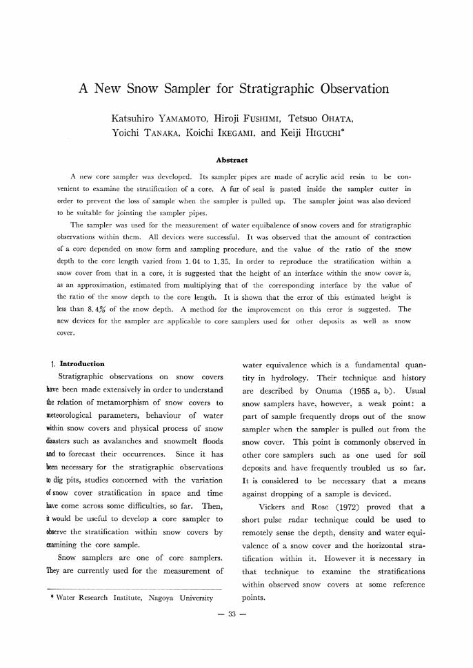
A New Snow Sampler for Stratigraphic Observation
Katsuhiro YAMAMOTO, Hiroji FUSHIMI, Tetsuo OHATA, Yoichi TANAKA, Koichi IKEGAMI, and Keiji HIGUCHI*
Abstract
A new core sampler was developed. Its sampler pipes are made of acrylic acid resin to be con-
venient to examine the stratification of a core. A fur of seal is pasted inside the sampler cutter in
order to prevent the loss of sample when the sampler is pulled up. The sampler joint was also deviced
to be suitable for jointing the sampler pipes.
The sampler was used for the measurement of water equibalence of snow covers and for stratigraphic
observations within them. All devices were successful. It was observed that the amount of contraction
of a core depended on snow form and sampling procedure, and the value of the ratio of the snow
depth to the core length varied from 1. 04 to 1. 35. In order to reproduce the stratification within a
snow cover from that in a core, it is suggested that the height of an interface within the snow cover is,
as an approximation, estimated from multiplying that of the corresponding interface by the value of
the ratio of the snow depth to the core length. It is shown that the error of this estimated height is
less than 8. 4% of the snow depth. A method for the improvement on this error is suggested. The
new devices for the sampler are applicable to core samplers used for other deposits as well as snow
cover.
1, Introduction
Stratigraphic observations on snow covers
have been made extensively in order to understand
the relation of metamorphism of snow covers to
meteorological parameters, behaviour of water
within snow covers and physical process of snow
disasters such as avalanches and snowmelt floods
and to forecast their occurrences. Since it has
been necessary for the stratigraphic observations
to dig pits, studies concerned with the variation
of snow cover stratification in space and time
have come across some difficulties, so far. Then,
it would be useful to develop a core sampler to
observe the stratification within snow covers by
examining the core sample.
Snow samplers are one of core samplers.
They are currently used for the measurement of
water equivalence which is a fundamental quan-
tity in hydrology. Their technique and history
are described by Onuma (1955 a, b). Usual
snow samplers have, however, a weak point : a
part of sample frequently drops out of the snow sampler when the sampler is pulled out from the
snow cover. This point is commonly observed in
other core samplers such as one used for soil
deposits and have frequently troubled us so far.
It is considered to be necessary that a means
against dropping of a sample is deviced.
Vickers and Rose (1972) proved that a
short pulse radar technique could be used to
remotely sense the depth, density and water equi-
valence of a snow cover and the horizontal stra-
tification within it. However it is necessary in
that technique to examine the stratifications
within observed snow covers at some reference
points.* Water Research Institute, Nagoya University
33
142 雪 氷39巻 3号 1977 年
The present experiments were carried out to
develop a core sampler which could be used for
stratigraphic observations of snow covers and the
measurement of water equivalence, simultane-
ously. The device against dropping of a sample
was also made. It is considered that this device
is also useful to core samplers used for other
deposits as well as snow cover.
2. Design for the Core Sampler The core sampler developed in the present
experiments is shown in Fig. 1. The pipe of the
sampler was made of acrylic acid resin to observe
the structure of core samples. Acrylic acid resin
was employed because of adequency in trans-
parency, mechanical strength and hardness. Although the resin is brittler than metals, no
trouble has occurred in our snow survey where
the sampler has been extended up to 3 m in
length by jointing the sampler pipes. In order
to obtain the nearly same cross-section area of
the sampler cutter as that of a 69 type snow
sampler developed by Meteorological Agency of
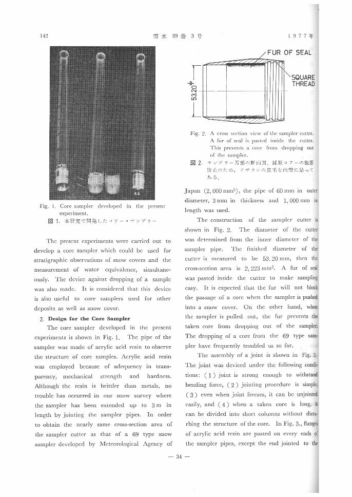
Japan (2, 000 mm2), the pipe of 60 mm in outer diameter, 3 mm in thickness and 1, 000 mm in
length was used.
The construction of the sampler cutter is
shown in Fig. 2. The diameter of the cutter
was determined from the inner diameter of the
sampler pipe. The finished diameter of the
cutter is measured to be 53. 20 mm, then the
cross-section area is 2, 223 mm2. A fur ofseal
was pasted inside the cutter to makesampling
easy. It is expected that the fur will notblock
the passage of a core when the sampler ispushed
into a snow cover. On the other hand, when
the sampler is pulled out, the fur prevents the
taken core from dropping out of the sampler.
The dropping of a core from the 69 type sam-
pler have frequently troubled us so far.The assembly of a joint is shown in Fig. 3,
The joint was deviced under the followingcondi-
tions: ( 1 ) joint is strong enough to withstand
bending force, ( 2 ) jointing procedure issimple,
( 3 ) even when joint freezes, it can beunjointedeasily, and ( 4 ) when a taken core is long, it
can be divided into short columns withoutdistu-
rbing the structure of the core. In Fig.3.,flanges
of acrylic acid resin are pasted on every ends of
the sampler pipes, except the end jointed to the
Fig. 1. Core sampler developed in the present
experiment.
図1, 本 研 究 で開 発 した コア ー ・サ ソプ ラー
Fig. 2. A cross section view of the sampler cutter.
A fur of seal is pasted inside the cutter.
This prevents a core from dropping out
of the sampler.
図2. サ ソプ ラー刃 部 の断 面 図.採 取 コ ア ーの脱落
防 止 の た め,ア ザ ラ シの皮 毛 を 内壁 に貼 って
あ る.
34
9月 A New Snow Sampler for Stratigraphic Observation 143
cutter. Two pipes with flanges are jointed by a
coupler of metal. The coupler consists of two
half-cylinders whose cross-section is shown in Fig.
3. Two half-cylinders are jointed by a hinge
and can be fastened by two catches. The catch
consists of a phosphor bronze belt, which is used
for a hasp, and a pin, which is used for a staple.
The pin is soldered on one of the half-cylinder
of the coupler. The belt is soldered at one end
on the other half-cylinder and has, at another
end, a hole to catch that pin. The catch is
buried in a groove on the outside of the coupler.
(We have a plan of changing the type of the catch into such type as one used in a keyholder
and a toolbox for simpler handling). In order
to transmit rotations about the axis of the sam-
pler across the joint, each flange has a groove
parallel to the axis of the sampler pipe and a
pin soldered on the inside of the coupler is put in the grooves of two flanges.
3. Observation
The sampler developed in the present experi-
ments was tested in the snow survey in hilly
countries around the Lake Biwa on 7-11 March,
1977. All our devices were successful.
3.1 Effect of the fur of seal The fur of seal pasted inside the sampler
cutter was so effective that dropping of a taken
core from the sampler was not observed in sam-
plings more than a hundred times. There was a
possibility that a little friction between the fur
and a core during pushing the sampler into a
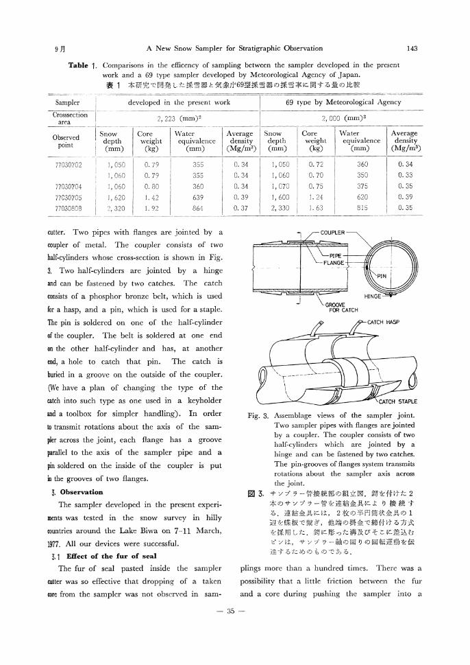
Table 1. Comparisons in the efficency of sampling between the sampler developed in the present work and a 69 type sampler developed by Meteorological Agency of Japan.
表1 本研究で開発 した採 雪器 と気象庁69型 採雪器 の採雪率 に関す る量の比較
Fig. 3. Assemblage views of the sampler joint. Two sampler pipes with flanges are jointed by a coupler. The coupler consists of two half-cylinders which are jointed by a hinge and can be fastened by two catches. The pin-grooves of flanges system transmits rotations about the sampler axis across the joint.
図3. サ ソ プ ラ ー管 接 続 部 の組 立 図.鍔 を 付 け た2
本 のサ ソ プ ラー管 を連 結 金 具 に よ り接 続 す
る.連 結 金 具 に は,2枚 の半 円 筒 状金 具 の1
辺 を蝶 板 で繋 ぎ,他 端 の 掛 金 で 締 付 け る方式
を採 用 した.鍔 に彫 った 溝 及 び そ こに 差 込 む
ピ ソは,サ ソプ ラー軸 の回 りの 回 転 運 動 を 伝
達 す るた め の も の で あ る.
35
144 雪 氷39巻 3号 1977 年
snow cover caused the effective diameter of the
cutter to decrease, because of the same reason
discussed by Onuma (1955 b) on the relation
between the effective diameter of a cutter and
snow depth. Therefore, we compared the values
of water equivalence and average density measured
using our sampler with those measured using the
69type snow sampler (Table 1). It was concluded
from Table 1 that the effect of the friction on
the effective diameter of the cutter can be negle-
cted, although the accurate effective diameter
must be calibrated on the basis of the statistical
treatment of results measured in homogeneous
snow covers over observation fields. It is reason-
able to consider that the friction between the fur
and a core also causes the contraction of the
core to increase. However, the amount of the
contraction due to the friction was not examined.
3. 2 Contraction of core
The amount of contraction of a core depends
upon form of snow and procedure of sampling.
In the case of new snow, the faster the sampler
is pushed into a snow cover, the less its amount
is. In the case of granular snow, the slower the
sampler is pushed, the less it is. When the
sampler is shaken up-and-down during sampling,
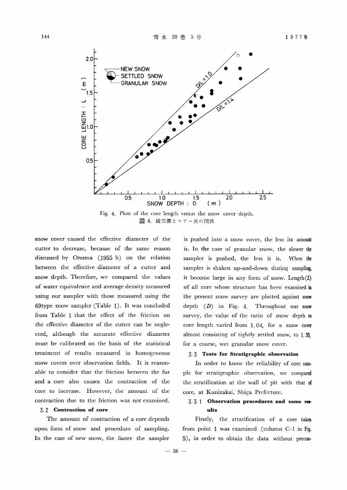
it become large in any form of snow. Length (L)
of all core whose structure has been examined in
the present snow survey are plotted against snow
depth (D) in Fig. 4. Throughout our snow
survey, the value of the ratio of snow depth to
core length varied from 1. 04, for a snow cover
almost consisting of tightly settled snow, to 1.35,
for a coarse, wet granular snow cover.
3. 3 Tests for Stratigraphic observation
In order to know the reliability of core same
pie for stratigraphic observation, we compared the stratification at the wall of pit with that of
core, at Kunizakai, Shiga Prefecture.
3. 3. 1 Observation procedures and some res-ults
Firstly, the stratification of a core taken
from point 1 was examined (column C-1 in Fig.
5), in order to obtain the data without precon.
Fig. 4. Plots of the core length versus the snow cover depth.
図4. 積 雪深 とコ ア ー 長 の 関係
36
9月 A New Snow Sampler for Stratigraphic Observation 145
ceptions on the stratification within the snow
cover. Secondly, the stratification was examined
by digging a pit at point 2 (column P-2 in Fig.
5) . The pit was dug approximately 10 m apart
from point 1, since the snow surface around point
1 had been distrurbed during sampling at point
1. Further, we pushed the sampler into the
snow cover at point 3 near the pit, and widened
the pit to point 4 close to point 3. The heights
of ice layers which showed the clear correspon-
dence between the core at point 3 and the snow
cover at point 4 were measured (columns C-3
and P-4 in Fig. 5), in order to study vertical
deformation of the core due to sampling. In the
case of core observation, it is generally difficult
to find a thin soaked layer and a thin ice layer
within coarse granular snow. However, in the
case of the core at point 3, it was easy, since
we knew the stratification of the snow cover at
point 4. But details of the stratifications of the core at point 3 and the snow cover at point 4
were not recorded.
The grain size of granular snow was classfied
into three classes : fine (f, smaller than 0. 3 mm
in diameter), medium (m, between 0. 3 and O. 8
mm) and coarse (c, larger than 0. 8 mm). Since
the size measured in the snow cover were mostly
smaller than 1. 0 mm, the classification recom-
mended by INTERNATIONAL UNION OF GEOD
ESY AND GEOPHYSICS (IUGG) was not appro-
priate. Results of the observations are shown in
Figs. 5 and 6. In the column in Fig. 5, thin
lines, thick lines and dark bands indicate interfaces
without ice layer, thin ice layer ( < 3 mm) and
thick ice layer (> 3 mm), respectively. Soaked
layers and dirty layers are marked by simple
hatchings and cross hatchings, respectively. Some
correlations between the columns are expressed
by thin lines. It has to be noted that details of
stratifications of the columns, C-3 and P-4 are
not shown as described above. The profile of
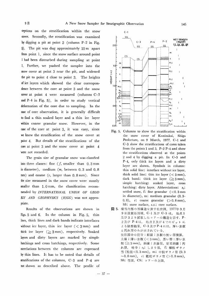
Fig. 5. Columns to show the stratification within the snow cover of Kunizakai, Shiga Prefecture, on 9 March, 1977. C-1 and C-3 show the stratifications of cores taken from the points 1 and 3. P-2 P-4 and show the stratifications observed at the points 2 and 4 by digging a pit. In C-3 and P-4, only thick ice layers and a dirty layer are shown. Symbols in column: thin solid line; interface without ice layer, thick solid line; thin ice layer (< 3 mm), dark band; thick ice layer (> 3 mm), simple hatching; soaked layer, cross hatching; dirty layer. Abbreviations: s2; settled snow, f; fine granular (<0. 3 mm in diameter), m; medium granular (0. 3- 0. 8), c; coarse granular (> 0. 8 mm), SS ; snow surface, c.s. ; core surface.
図5. 積 雪 内 部 の 層構 造 を 表 す 柱 状 図.1977年3月
9日 滋 賀 県 国境.C4及 びC-3は,地 点1
及 び3よ り採 取 した コ アー の構 造 を示 す. P-
2及 びP-4は,地 点2及 び4で の ピ ッ ト に
よる観 察 結 果.C-3及 びP-4に は,厚 い氷 板
と汚 れ 層 の みが 示 され て い る。
柱 状 図 中 の記 号:細 線;氷 板 の無 い層 境 界,
太 線;薄 い氷 板(<3mm),黒 い帯;厚 い氷
板(≧3mm),斜 線;水 滲 層,交 叉 斜 線;汚
れ 層.略 号:s3;し ま り雪,f;細 粒 ザ ラ メ
雪(粒 径 く0.3mm),m;中 粒 ザ ラ メ雪(0。3
~0.8mm),6;粗 粒 ザ ラ メ雪(>0 。8mm),
SS;雪 面, CS;コ ア ーの 上 面 .
37
146 雪 氷39巻 3号 1977 年
wet density at point 2 is also shown in Fig. 5 for
a reference to the snow form.
3. 3. 2 Reproduction of snow cover stratifica-
tion from core stratification
In order to reproduce stratification within a
snow cover from that of a core, positions of
interfaces within the snow cover have to be
estimated from those in the core. Plots of the
height of an ice layer within the snow cover at
point 4 versus that of the corresponding interface
in the core taken from point 3 are shown in Fig.
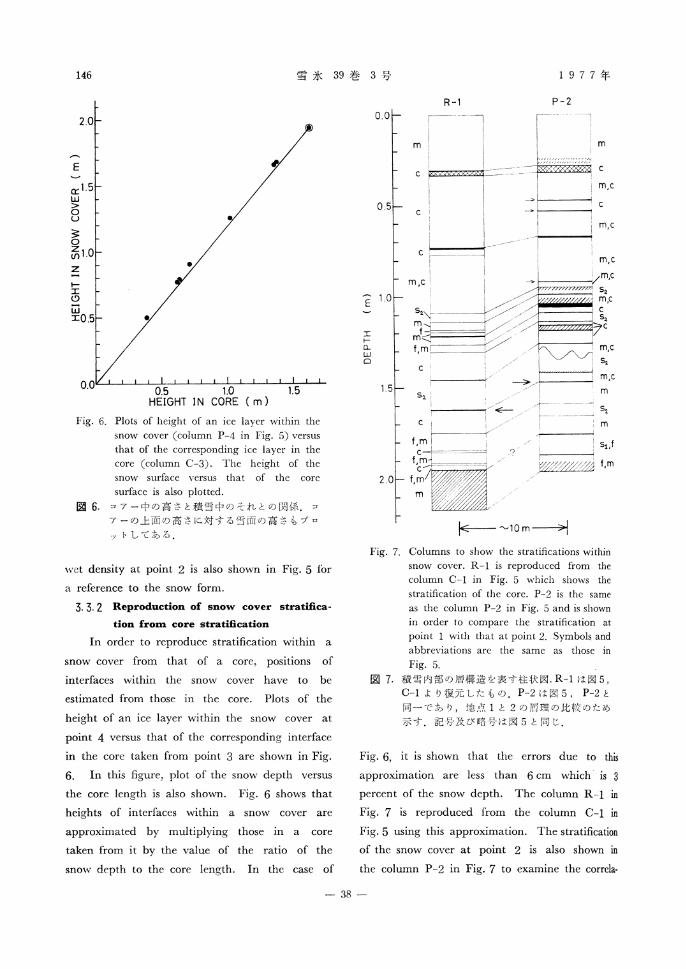
6. In this figure, plot of the snow depth versus
the core length is also shown. Fig. 6 shows that
heights of interfaces within a snow cover are
approximated by multiplying those in a core
taken from it by the value of the ratio of the
snow depth to the core length. In the case of
R-1 P-2
Fig. 6, it is shown that the errors due to this
approximation are less than 6 cm which is 3
percent of the snow depth. The column R-1 in
Fig. 7 is reproduced from the column C-1 in
Fig. 5 using this approximation. The stratification
of the snow cover at point 2 is also shown in
the column P-2 in Fig. 7 to examine the correla-
Fig. 6. Plots of height of an ice layer within the snow cover (column P-4 in Fig. 5) versus that of the corresponding ice layer in the core (column C-3). The height of the snow surface versus that of the core surface is also plotted.
図6. コア ー 中 の 高 さ と積 雪 中 の そ れ との 関係.コ
ア ー の上 面 の高 さ に対 す る雪 面 の高 さ も プ ロ
ッ トして あ る。
Fig. 7. Columns to show the stratifications within
snow cover. R-1 is reproduced from the
column C-1 in Fig. 5 which shows the
stratification of the core. P-2 is the same
as the column P-2 in Fig. 5 and is shown
in order to compare the stratification at
point 1 with that at point 2. Symbols and abbreviations are the same as those in
Fig. 5.
図7. 積 雪 内部 の層 構 造 を表 す 柱 状 図.R4は 図5,
C-1よ り復 元 した も の。P-2は 図5,P-2と
同一 で あ り,地 点1と2の 層 理 の比 較 の ため
示 す.記 号 及 び 略 号 は 図5と 同 じ。
38
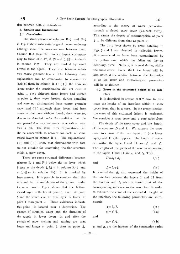
9月 A New Snow Sampler for Stratigraphic Observation 147
tion between both stratifications.
4. Results and Discussions
4. 1 Correlation
The stratifications of columns R-1 and P-2
in Fig. 7 show substantially good correspondences
although some differences are seen between them.
Column R-1 lacks the thin ice layers correspon-
ding to those of 0. 47, O. 53 and 0. 92 m in depth
in column P-2. They are marked by small
arrows in the figure. They exist between relati-
vely coarse granular layers. The following three
explanations can be conceivable to account for
lack of them in column R-1 : (1) the thin ice
layers under the consideration did not exist at
point 1, ( 2 ) although these layers had existed at point 1, they were broken during sampling
and were not distinguished from coarse granular
snow, and ( 3 ) although these layers had been
taken in the core without break, they were too
thin to be detected under the condition that the
core provided a very narrower observation area
than a pit. The same three explanations can
also be conceivable to account for lack of some
soaked layers in column R-1. The explanations,
( 2 ) and ( 3 ), show that observations with core
are not suitable for examining the fine structure
within a snow cover.
There are some structual differences between
columns R-1 and P-2 below the ice layer which
is seen at the depth 1. 62 m in column R-1 and
at 1. 47 m in column P-2. It is marked by
large arrows. It is possible to consider that this
is caused by the undulation of the ground under
the snow cover. Fig. 7 shows that the bottom
soaked layer is thicker at point 1 than at point
2 and the water level of this layer is lower at
point 1 than point 2. These evidences indicate that point 1 is located near a depression. The
amount of supplied water and the duration of
the supply in lower layers, in and after the
periods of snow melting and raining are then larger and longer at point 1 than at point 2,
according to the theory of water percolation
through a sloped snow cover (Colbeck, 1975).
This causes the degree of metamorphism at point
1 to be different from that at point 2.
The dirty layer shown by cross hatching in
Figs. 5 and 7 was observed in yellowish brown.
It is considered to have been contaminated by
the yellow sand which has fallen on 22•`24
February, 1977. Namely, it is good dating within
the snow cover. Some thick ice layers will be
also dated if the relation between the formation
of an ice layer and meteorological parameters
will be established.
4. 2 Error in the estimated height of an inte-
rface
It is described in section 3. 3. 2 how to esti-
mate the height of an interface within a snow
cover from that in a core. In the present section,
the error of this estimated height is evaluated.
We consider a snow cover and a core taken from
it. The depth of the snow cover and the length
of the core are D and L. We suppose the snow
cover to consist of the two layers : I (the lower
layer) and II (the upper). The length of verti-
cals within the layers I and II are d1 and d2.
The lengths of the parts of the core corresponding
to the layers I and II are 11 and 12. Then,
( 1 )and
( 2 )
It is noted that d1 also expressed the height of
the interface between the layers I and II from
the bottom and 11 also expressed that of the
corresponding interface in the core, too. In order
to evaluate the error of the estimated height of
the interface, the following parameters are intro-
duced:
( 3 )
(4 a)and
(4 b)
al and a2 are the inverses of the contraction ratios
39
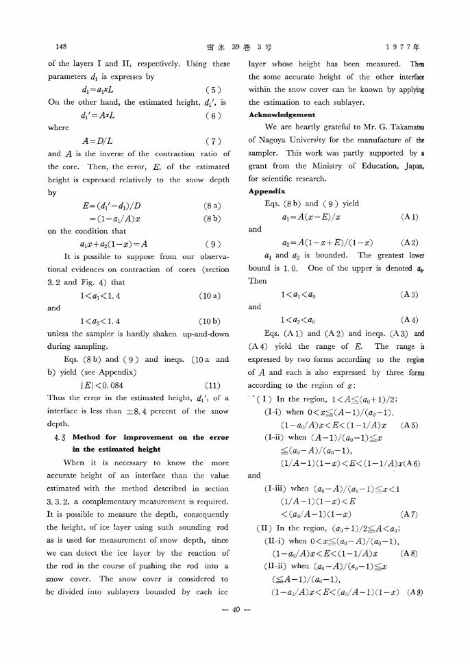
148 雪 氷39巻 3号 1977 年
of the layers I and II, respectively. Using these
parameters d1 is expresses by
( 5 )On the other hand, the estimated height, d1', is
( 6 )
where
( 7 )and A is the inverse of the contraction ratio of
the core. Then, the error, E, of the estimated
height is expressed relatively to the snow depth
by
(8 a)
(8 b)on the condition that
( 9 )It is possible to suppose from our observa-
tional evidences on contraction of cores (section
3.2 and Fig. 4) that
(10 a)and
(10 b)unless the sampler is hardly shaken up-and-down
during sampling.
Eqs. (8 b) and ( 9 ) and ineqs. (10 a and
b) yield (see Appendix)
( 11 )Thus the error in the estimated height, d11, of a
interface is less than •}8. 4 percent of the snow
depth.
4. 3 Method for improvement on the error
in the estimated height
When it is necessary to know the more
accurate height of an interface than the value
estimated with the method described in section
3. 3. 2, a complementary measurement is required.
It is possible to measure the depth, consequently
the height, of ice layer using such sounding rod
as is used for measurement of snow depth, since
we can detect the ice layer by the reaction of
the rod in the course of pushing the rod into a
snow cover. The snow cover is considered to
be divided into sublayers bounded by each ice
layer whose height has been measured. Then
the some accurate height of the other interface
within the snow cover can be known by applying
the estimation to each sublayer.
Acknowledgement
We are heartly grateful to Mr. G. Takamatsu
of Nagoya University for the manufacture of the
sampler. This work was partly supported by a
grant from the Ministry of Education, Japan, for scientific research.
Appendix
Eqs. (8 b) and ( 9 ) yield
(A 1)and
(A 2)a1 and a2 is bounded. The greatest lower
bound is 1. 0. One of the upper is denoted a0.
Then
(A 3)
and
(A 4)
Eqs. (A 1) and (A 2) and ineqs. (A 3) and
(A 4) yield the range of E. The range is expressed by two forms according to the region
of A and each is also expressed by three forms
according to the region of x:
( I ) In the region,
(I-i) when
(A 5)
(I-ii) when
(A 6)and
(I-iii) when
(A 7)
( II ) In the region,
(II-i) when
(A 8)
(II-ii) when
(A 9)
40
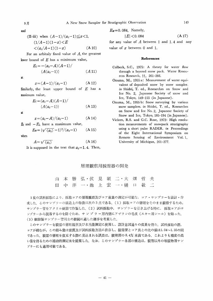
9月 A New Snow Sampler for Stratigraphic Observation 149
and
(II-iii) when
(A 10)
For an arbitaly fixed value of A, the greatest
lower bound of E has a minimum value,
(A 11)
at
(A 12)
Similarly, the least upper bound of E has a
maximum value,
(A 13)
at
(A 14)
Eu and EL have a maximum value,
(A 15)
when
(A 16)
It is supposed in the text that a0= 1. 4. Then,
EM = 0.084, Namely,
(A 17)
for any value of A between 1 and 1. 4 and any
value of x between 0 and 1.
References
Colbeck, S.C., 1975: A theory for water flow through a layered snow pack. Water Resou-rces Research, 11, 261-266.
Onuma, M., 1955 a: Measurement of water equi-valent of deposited snow by snow sampler. in Shidei, T. ed., Researches on Snow and Ice No. 2, Japanese Society of snow and Ice, Tokyo, 149-155 (in Japanese).
Onuma, M., 1955 b: Snow surveying by various snow samplers. in Shidei, T. ed., Researches on Snow and Ice No. 2, Japanese Society of Snow and Ice, Tokyo, 185-194 (in Japanese).
Vickers, R.S. and G.C. Rose, 1972: High resolu- tion measurements of snowpack stratigraphy using a short pulse RADER. in Proceedings of the Eight International Symposium on Remote Sensing of Environment Vol. 1, University of Michigan, 261-277.
層 理 観 察 用 採 雪 器 の 開 発
山 本 勝 弘 ・伏 見 碩 二 ・大 畑 哲 夫
田 中 洋 一 ・池 上 宏 一 ・樋 口 敬 二
1度 の試料採取に より,採 取コ アの層理観察及び コア重量の測定が可能な,コ ア ・サ ンプ ラーを設計 ・作
成した.こ のサ ンプラーの構造上 の特徴は次の3点 であ る.(1)採 取 コアの層理 をそのまま観 察す るため,
サンプラー管をア ク リル樹脂 で作製 した.(2)試 料採取中,サ ンプラーを引 き上げる時に,採 取コ アがサ
ンプラーか ら脱落す るのを防 ぐため,サ ン プ ラ ー刃内壁に アザ ラシの毛皮(ス キ ー用 シール)を 貼 った。
(3)樹 脂製サ ンプラー管 同士 の接続に適 した継手を考案 した.
このサ ンプラーを積雪 の層理観察及び水 当量測定に使用 し,設 計意図通 りの成果を得た.試 料採 取の際,
コアが縮むが,こ の縮 み量 は雪質及 び試料採取方法に依存 し,積 雪深 とコア長 との比の値 は1.04~1.35の 間
であった.積 雪の層理を復元す る際 に見込 まれ る誤差は,積 雪深の8.4%未 満であ る.こ れ よりも精度 の高
い値を得 るための補 助的測定 法を提案 した.な お,こ のサ ンプラー各部の構造は,積 雪 以外 の堆積物用サ ン
プラーに も適用可能である.
41