Embed Size (px)
Citation preview
Acta Polytechnica Hungarica Vol. 12, No. 3, 2015
– 199 –
A New Wind Turbine Concept: Design and Implementation
Bedri Kekezoğlu, Muğdeşem Tanrıöven, Ali Erduman Yildiz Technical University, Electrical and Electronics Faculity, Electrical Engineering Department, Istanbul, Turkey [email protected], [email protected], [email protected]
Abstract: Electrical energy demand has been continuously increasing. Depleting fossil fuel reserves, environmental concerns, and insufficiency of conventional generation techniques in meeting growing demand, renewable energy use has been widely adopted in the world. When considering the application of renewable energy sources in the world, it can be seen that wind energy is mostly preferred over other renewable energy sources. In this study, a new prototype wind energy conversion system suitable for urban use is designed and manufactured. The proposed design is modular and has flexible structure. In the new design, an outer gear ring attached to turbine blades is used. In the design stage, both the number of blades and the number of outer gear rings are varied to analyze their effect on turbine performance. Performance analysis of the prototype wind turbine is completed under real life conditions and results are given. As a result of this study, it is shown that increasing the gearwheels and blade numbers caused turbine output power increases. The most efficient structure identified during the field analysis is a three gearwheel with six blade system.
Keywords: renewable energy resources; wind energy; wind turbine prototype; urban use
1 Introduction
Wind energy outshines all other renewable energy resources due to the recent technological improvements. Electrical energy generation from wind power has increased rapidly and due to the increased interest many studies on efficient wind turbine design have been performed.
There are several studies about improvement of wind turbine performance in literature. Ameku et all. designed a 3 kW wind turbine prototype focusing on blade design [1]. Kosasih and Tondelli analyzed a low power turbine that has a conical structure to speed up air flow through the wind turbine in the laboratory environment [2]. Chong et al. presented a vertical axis wind turbine for high buildings [3]. A. Ali et al. developed a new vertical axis wind turbine. In the
B. Kekezoğlu et al. A New Wind Turbine Concept: Design and Implementation
– 200 –
study, the power generation potential of the system was analyzed and turbine blades were tested for different configuration and wind speed values [4]. Park et al. developed a 3 MW offshore wind turbine [5]. Solero et al. improved a wind turbine which is used for cold weather conditions [6]. Nagai et al. presented a performance of 3 kW wind turbine with a variable slope control system [7].
Although wind power plants contribute to electrical energy generation, they are built far away from consumption centers due to several factors such as, large area needed (not suitable for urban use), shadow effect and noise problems. Therefore, a new wind turbine design for the cities, which has low wind speed profile and high-population-density considerations, becomes a critical need.
Mainly, wind turbines that are used in urban areas, and produce power at low wind speeds, should be visually compatible with the environment and should work with low noise. In determining mounted places of wind turbines used in urban areas, turbulence should be minimized by taking into account the surrounding structures. Despite these challenges, there remains a growing interest for roof mounted wind turbines [8, 9, 10].
In this study, a new mini wind turbine concept suitable for urban use and low wind speeds is demonstrated. The mini wind turbine concept has a modular structure and can be optimized for different conditions and wind sites. In this paper, performance analyses of the mini wind turbine concept are performed and the results are summarized.
The paper is organized as follows: General information and mathematical background of this study is given in Section II. The design parameters, details of proposed wind turbine and obtained results are presented in Section III. Analysis of the results and future studies are given in Section IV. Section V presents the conclusion.
2 Wind Energy Conversion Systems
Wind energy conversation systems (WECS) has become the most useful renewable energy source among all others. World Wind Energy Association (WWEA) data shows that installed wind power is 254 GW as of mid-year 2012. Also, it is expected that installed wind power will be 273 GW by the end of 2012 [11]. European Union generated %6,3 of its energy using 93,6 GW from installed wind power in the year 2011 [12].
As known, kinetic energy of wind is converted to electrical energy by using wind turbines. Mechanical power production of a wind turbine is given in Equation 1 [13].
Acta Polytechnica Hungarica Vol. 12, No. 3, 2015
– 201 –
)(...21 3 WCvAP pm ρ⋅=
(1)
where, Pm, turbine mechanical power output, ρ, air density, A, turbine swept area, v, wind speed and Cp, turbine power coefficient. Power coefficient varies with blade tip speed ratio (λ) and blade angle (ϑ). Power coefficient of a wind turbine could be calculated by using Equation 2 and Equation 3, respectively.
βϑϑβ
ϑλ1
54321p61),(C
cx eccccc
−
−−−=
(2)
31035.0
08.011
ϑϑλβ +−
+= (3)
Coefficients used in Eq. 2 are empirical constants. Blade tip speed ratio could be obtained by Equation 4.
vRϖλ = (4)
where, R, blade diameter and ω, angular velocity of turbine blade.
3 Mini Wind Turbine Concept
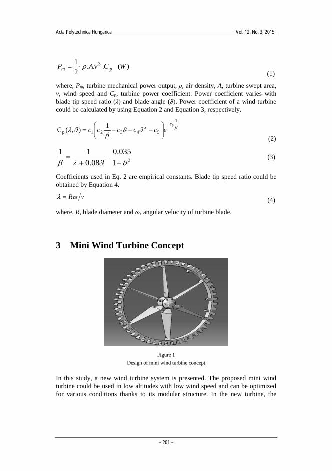
Figure 1 Design of mini wind turbine concept
In this study, a new wind turbine system is presented. The proposed mini wind turbine could be used in low altitudes with low wind speed and can be optimized for various conditions thanks to its modular structure. In the new turbine, the
B. Kekezoğlu et al. A New Wind Turbine Concept: Design and Implementation
– 202 –
turbine blades are located in the gearwheels. Thus, the swept area can be adjusted according to the requirements. The designed system is shown in Figure 1.
The realized wind turbine prototype is designed to obtain maximum output power with the smallest blades possible. The blades could be coupled to the outer gearwheel. Thereby, surface area could be increased to achieve higher output power. The outer gearwheel is flexible for variable blade numbers. This feature provides optimum system designs for different wind sites.
3.1 Design Studies
All components of new mini wind energy conversion system are individually designed. Blades, outer gearwheel and other components of the system are respectively designed and realized. Following sub-sections explains design details.
3.1.1 Blade Design
The introduced mini wind turbine concept is envisaged to produce high power for low wind speeds. Therefore, the blade structure is designed for low wind speed conditions with high efficiency. The blade type S833 which was developed by National Renewable Energy Laboratory (NREL) is used for the prototype system. This blade profile is placed in a thick blade category with a 18% blade thickness ratio. Also, this type of blade is especially used up to 1-3 m blade diameters.
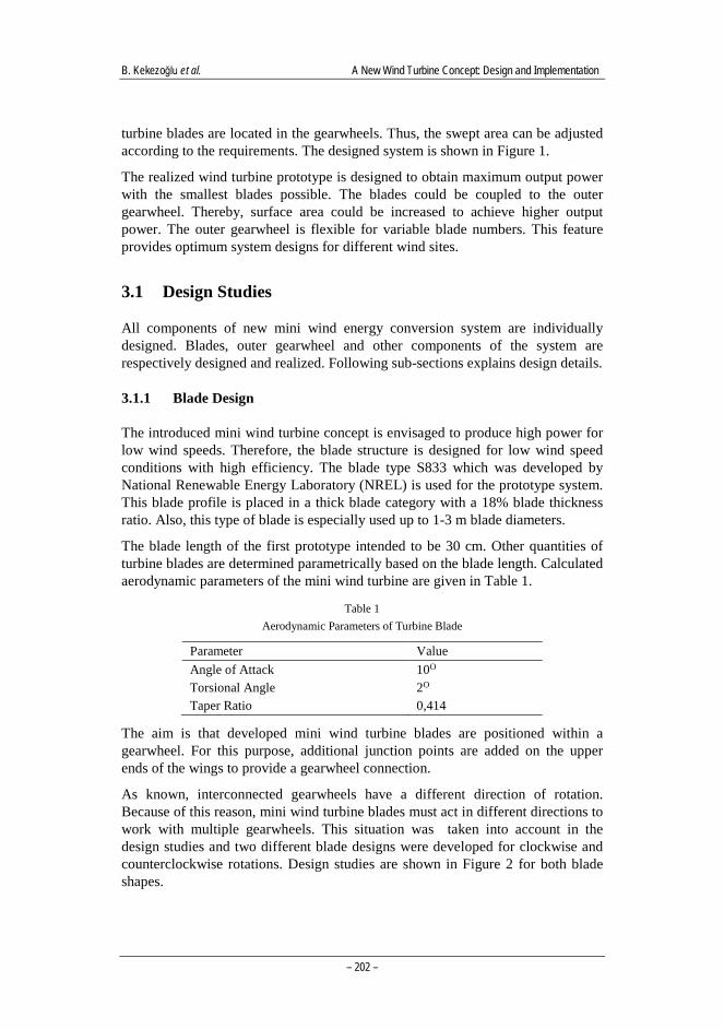
The blade length of the first prototype intended to be 30 cm. Other quantities of turbine blades are determined parametrically based on the blade length. Calculated aerodynamic parameters of the mini wind turbine are given in Table 1.
Table 1 Aerodynamic Parameters of Turbine Blade
Parameter Value Angle of Attack 10O Torsional Angle 2O Taper Ratio 0,414
The aim is that developed mini wind turbine blades are positioned within a gearwheel. For this purpose, additional junction points are added on the upper ends of the wings to provide a gearwheel connection.
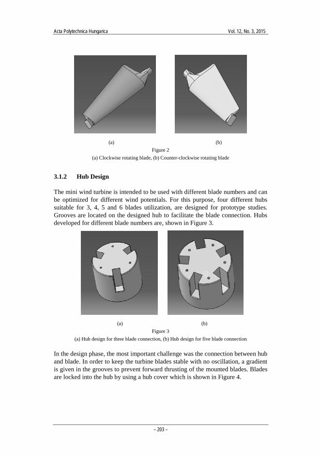
As known, interconnected gearwheels have a different direction of rotation. Because of this reason, mini wind turbine blades must act in different directions to work with multiple gearwheels. This situation was taken into account in the design studies and two different blade designs were developed for clockwise and counterclockwise rotations. Design studies are shown in Figure 2 for both blade shapes.
Acta Polytechnica Hungarica Vol. 12, No. 3, 2015
– 203 –
(a) (b) Figure 2
(a) Clockwise rotating blade, (b) Counter-clockwise rotating blade
3.1.2 Hub Design
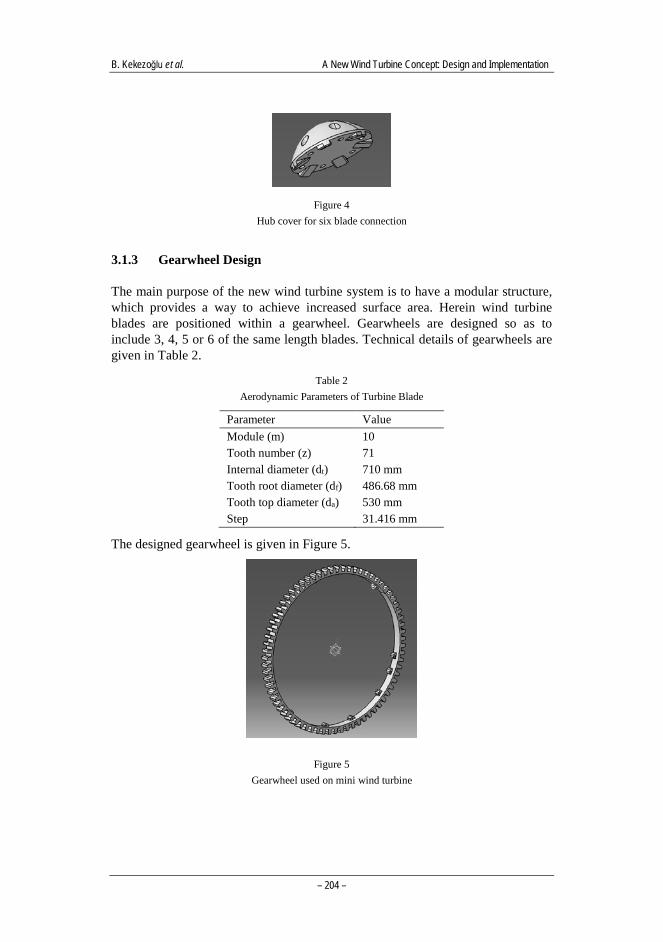
The mini wind turbine is intended to be used with different blade numbers and can be optimized for different wind potentials. For this purpose, four different hubs suitable for 3, 4, 5 and 6 blades utilization, are designed for prototype studies. Grooves are located on the designed hub to facilitate the blade connection. Hubs developed for different blade numbers are, shown in Figure 3.
(a) (b) Figure 3
(a) Hub design for three blade connection, (b) Hub design for five blade connection
In the design phase, the most important challenge was the connection between hub and blade. In order to keep the turbine blades stable with no oscillation, a gradient is given in the grooves to prevent forward thrusting of the mounted blades. Blades are locked into the hub by using a hub cover which is shown in Figure 4.
B. Kekezoğlu et al. A New Wind Turbine Concept: Design and Implementation
– 204 –
Figure 4 Hub cover for six blade connection
3.1.3 Gearwheel Design
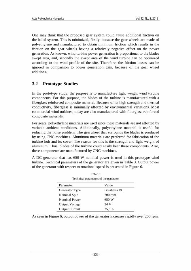
The main purpose of the new wind turbine system is to have a modular structure, which provides a way to achieve increased surface area. Herein wind turbine blades are positioned within a gearwheel. Gearwheels are designed so as to include 3, 4, 5 or 6 of the same length blades. Technical details of gearwheels are given in Table 2.
Table 2 Aerodynamic Parameters of Turbine Blade
Parameter Value Module (m) 10 Tooth number (z) 71 Internal diameter (dt) 710 mm Tooth root diameter (df) 486.68 mm Tooth top diameter (da) 530 mm Step 31.416 mm
The designed gearwheel is given in Figure 5.
Figure 5 Gearwheel used on mini wind turbine
Acta Polytechnica Hungarica Vol. 12, No. 3, 2015
– 205 –
One may think that the proposed gear system could cause additional friction on the baled system. This is minimized, firstly, because the gear wheels are made of polyethylene and manufactured to obtain minimum friction which results in the friction on the gear wheels having a relatively negative effect on the power generation. As known, wind turbine power generation is proportional to the blades swept area, and, secondly the swept area of the wind turbine can be optimized according to the wind profile of the site. Therefore, the friction losses can be ignored in comparison to power generation gain, because of the gear wheel additions.
3.2 Prototype Studies
In the prototype study, the purpose is to manufacture light weight wind turbine components. For this purpose, the blades of the turbine is manufactured with a fiberglass reinforced composite material. Because of its high strength and thermal conductivity, fiberglass is minimally affected by environmental variations. Most commercial wind turbines, today are also manufactured with fiberglass reinforced composite materials.
For gears, polyethylene materials are used since these materials are not affected by variable ambient conditions. Additionally, polyethylene material is useful for reducing the noise problem. The gearwheel that surrounds the blades is produced by using CNC machines. Aluminum materials are preferred for fabrication of the turbine hub and its cover. The reason for this is the strength and light weight of aluminum. Thus, blades of the turbine could easily bear these components. Also, these components are manufactured by CNC machines.
A DC generator that has 650 W nominal power is used in this prototype wind turbine. Technical parameters of the generator are given in Table 3. Output power of the generator with respect to rotational speed is presented in Figure 6.
Table 3 Technical parameters of the generator
Parameter Value Generator Type Brushless DC Nominal Spin 700 rpm Nominal Power 650 W Output Voltage 24 V Output Current 25,8 A
As seen in Figure 6, output power of the generator increases rapidly over 200 rpm.
B. Kekezoğlu et al. A New Wind Turbine Concept: Design and Implementation
– 206 –
Figure 6 Generator characteristics
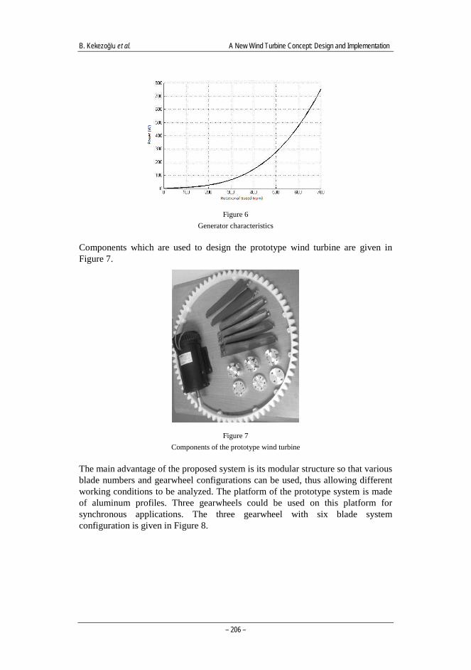
Components which are used to design the prototype wind turbine are given in Figure 7.
Figure 7 Components of the prototype wind turbine
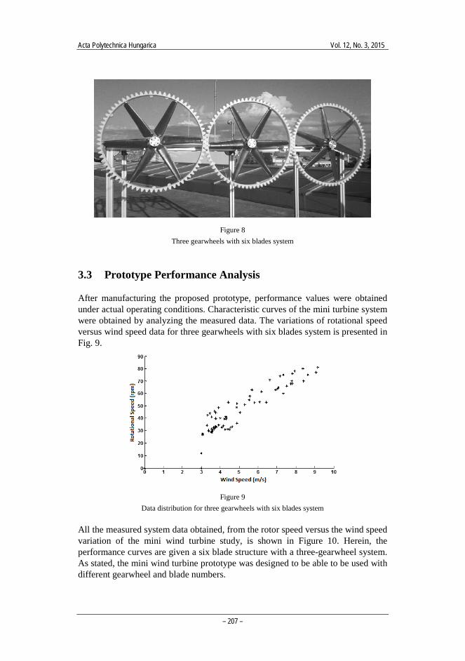
The main advantage of the proposed system is its modular structure so that various blade numbers and gearwheel configurations can be used, thus allowing different working conditions to be analyzed. The platform of the prototype system is made of aluminum profiles. Three gearwheels could be used on this platform for synchronous applications. The three gearwheel with six blade system configuration is given in Figure 8.
Acta Polytechnica Hungarica Vol. 12, No. 3, 2015
– 207 –
Figure 8 Three gearwheels with six blades system
3.3 Prototype Performance Analysis
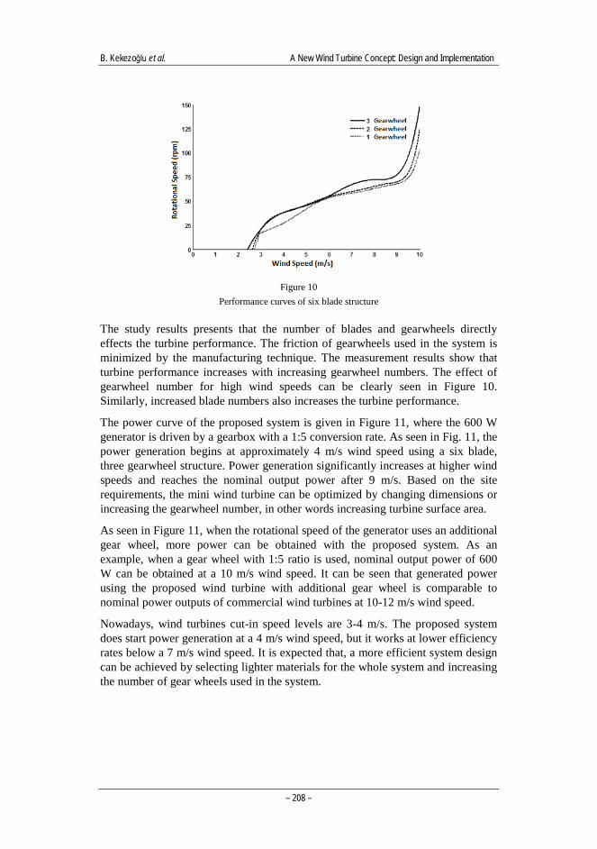
After manufacturing the proposed prototype, performance values were obtained under actual operating conditions. Characteristic curves of the mini turbine system were obtained by analyzing the measured data. The variations of rotational speed versus wind speed data for three gearwheels with six blades system is presented in Fig. 9.
Figure 9 Data distribution for three gearwheels with six blades system
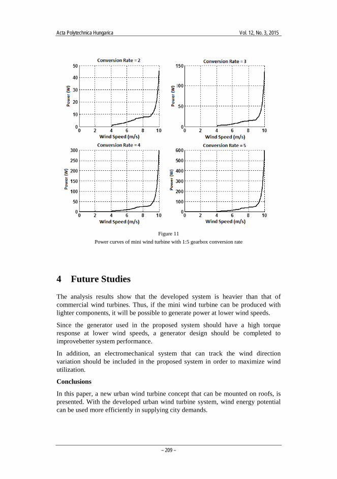
All the measured system data obtained, from the rotor speed versus the wind speed variation of the mini wind turbine study, is shown in Figure 10. Herein, the performance curves are given a six blade structure with a three-gearwheel system. As stated, the mini wind turbine prototype was designed to be able to be used with different gearwheel and blade numbers.
B. Kekezoğlu et al. A New Wind Turbine Concept: Design and Implementation
– 208 –
Figure 10 Performance curves of six blade structure
The study results presents that the number of blades and gearwheels directly effects the turbine performance. The friction of gearwheels used in the system is minimized by the manufacturing technique. The measurement results show that turbine performance increases with increasing gearwheel numbers. The effect of gearwheel number for high wind speeds can be clearly seen in Figure 10. Similarly, increased blade numbers also increases the turbine performance.
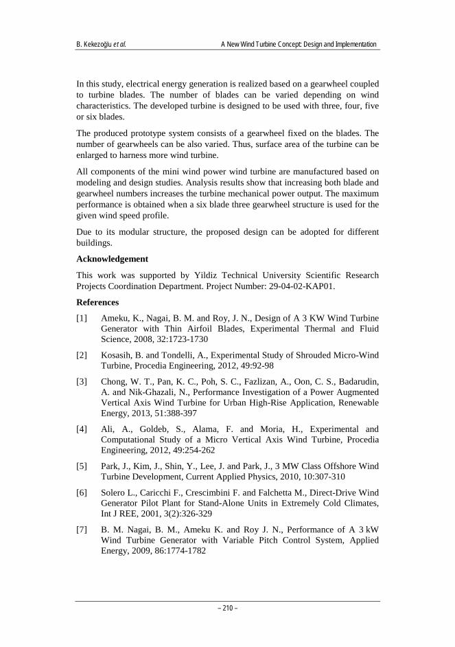
The power curve of the proposed system is given in Figure 11, where the 600 W generator is driven by a gearbox with a 1:5 conversion rate. As seen in Fig. 11, the power generation begins at approximately 4 m/s wind speed using a six blade, three gearwheel structure. Power generation significantly increases at higher wind speeds and reaches the nominal output power after 9 m/s. Based on the site requirements, the mini wind turbine can be optimized by changing dimensions or increasing the gearwheel number, in other words increasing turbine surface area.
As seen in Figure 11, when the rotational speed of the generator uses an additional gear wheel, more power can be obtained with the proposed system. As an example, when a gear wheel with 1:5 ratio is used, nominal output power of 600 W can be obtained at a 10 m/s wind speed. It can be seen that generated power using the proposed wind turbine with additional gear wheel is comparable to nominal power outputs of commercial wind turbines at 10-12 m/s wind speed.
Nowadays, wind turbines cut-in speed levels are 3-4 m/s. The proposed system does start power generation at a 4 m/s wind speed, but it works at lower efficiency rates below a 7 m/s wind speed. It is expected that, a more efficient system design can be achieved by selecting lighter materials for the whole system and increasing the number of gear wheels used in the system.
Acta Polytechnica Hungarica Vol. 12, No. 3, 2015
– 209 –
Figure 11 Power curves of mini wind turbine with 1:5 gearbox conversion rate
4 Future Studies
The analysis results show that the developed system is heavier than that of commercial wind turbines. Thus, if the mini wind turbine can be produced with lighter components, it will be possible to generate power at lower wind speeds.
Since the generator used in the proposed system should have a high torque response at lower wind speeds, a generator design should be completed to improvebetter system performance.
In addition, an electromechanical system that can track the wind direction variation should be included in the proposed system in order to maximize wind utilization.
Conclusions
In this paper, a new urban wind turbine concept that can be mounted on roofs, is presented. With the developed urban wind turbine system, wind energy potential can be used more efficiently in supplying city demands.
B. Kekezoğlu et al. A New Wind Turbine Concept: Design and Implementation
– 210 –
In this study, electrical energy generation is realized based on a gearwheel coupled to turbine blades. The number of blades can be varied depending on wind characteristics. The developed turbine is designed to be used with three, four, five or six blades.
The produced prototype system consists of a gearwheel fixed on the blades. The number of gearwheels can be also varied. Thus, surface area of the turbine can be enlarged to harness more wind turbine.
All components of the mini wind power wind turbine are manufactured based on modeling and design studies. Analysis results show that increasing both blade and gearwheel numbers increases the turbine mechanical power output. The maximum performance is obtained when a six blade three gearwheel structure is used for the given wind speed profile.
Due to its modular structure, the proposed design can be adopted for different buildings.
Acknowledgement
This work was supported by Yildiz Technical University Scientific Research Projects Coordination Department. Project Number: 29-04-02-KAP01.
References
[1] Ameku, K., Nagai, B. M. and Roy, J. N., Design of A 3 KW Wind Turbine Generator with Thin Airfoil Blades, Experimental Thermal and Fluid Science, 2008, 32:1723-1730
[2] Kosasih, B. and Tondelli, A., Experimental Study of Shrouded Micro-Wind Turbine, Procedia Engineering, 2012, 49:92-98
[3] Chong, W. T., Pan, K. C., Poh, S. C., Fazlizan, A., Oon, C. S., Badarudin, A. and Nik-Ghazali, N., Performance Investigation of a Power Augmented Vertical Axis Wind Turbine for Urban High-Rise Application, Renewable Energy, 2013, 51:388-397
[4] Ali, A., Goldeb, S., Alama, F. and Moria, H., Experimental and Computational Study of a Micro Vertical Axis Wind Turbine, Procedia Engineering, 2012, 49:254-262
[5] Park, J., Kim, J., Shin, Y., Lee, J. and Park, J., 3 MW Class Offshore Wind Turbine Development, Current Applied Physics, 2010, 10:307-310
[6] Solero L., Caricchi F., Crescimbini F. and Falchetta M., Direct-Drive Wind Generator Pilot Plant for Stand-Alone Units in Extremely Cold Climates, Int J REE, 2001, 3(2):326-329
[7] B. M. Nagai, B. M., Ameku K. and Roy J. N., Performance of A 3 kW Wind Turbine Generator with Variable Pitch Control System, Applied Energy, 2009, 86:1774-1782
Acta Polytechnica Hungarica Vol. 12, No. 3, 2015
– 211 –
[8] L. Ledo, P. B. Kosasih and P. Cooper, Roof Mounting Site Analysis For Micro-Wind Turbines, Renewable Energy, 2011, 36:1379-1391
[9] Y. F. Wang and M S. Zhan., 3- Dimentional CFD Simulation and Analysis on Performance of a Micro-Wind Turbine Resembling Lotus In Shape, Energy ang Buildings, 2013, 65:66-74
[10] L. Santoli, A. Albo, D. A. Garcia, D. Bruschi and F. Cuma, A Preliminary Energy and Enviromental Assessment of a Micro Wind Turbine Prototype In Natural Protected Areas, Sustainable Energy Technologies and Assessments, 2014, 8:42-56
[11] WWEA, World Wind Energy Association. 2012 Half year report. WWEA; 2012
[12] EWEA, The European Wind Energy Association. A report by The European Wind Energy Association 2011. Belgium: EWEA; 2011
[13] Gilbert, M. M., Renewable and Efficient Electric Power Systems, 2004, John Wiley & Sons, USA