Embed Size (px)
Citation preview
A Nonredundant Spherical NF-FF Transformation:
Experimental Tests @ UNISA Antenna
Characterization Lab Francesco D’Agostino
#1, Flaminio Ferrara
#1, Claudio Gennarelli
#1, Rocco Guerriero
#1,
Massimo Migliozzi#1
, Giovanni Riccio
*2
# D.I.I.N., University of Salerno
via Ponte Don Melillo, 84084 Fisciano, Italy 1 [email protected]
* D.I.E.M., University of Salerno
via Ponte Don Melillo, 84084 Fisciano, Italy 2 [email protected]
Abstract— An experimental validation of a near-field – far-
field transformation technique with spherical scanning for quasi-
planar antennas requiring a minimum number of near-field data
is provided in this work. Such a technique is based on the
nonredundant sampling representations of the electromagnetic
fields and on the optimal sampling interpolation expansions, and
makes use of an oblate ellipsoid to model the antenna. It is so
possible to remarkably lower the number of data to be acquired,
thus reducing in a significant way the measurement time. The
effectiveness of such a technique is experimentally assessed at the
UNISA Antenna Characterization Lab by comparing the far-
field patterns reconstructed from nonredundant measurements
on the sphere with those obtained from the near-field data
directly measured on the classical spherical grid.
I. INTRODUCTION
As well-known, for electrically large antennas, it is im-
practical to directly measure the radiation patterns on a con-
ventional far-field (FF) range. Accordingly, for these anten-
nas, it is convenient to exploit near-field (NF) measurements
and recover the FF patterns via NF–FF transformation tech-
niques. In addition, the NF measurements can be carried out in
a controlled environment, such as an anechoic chamber, thus
overcoming those drawbacks due to weather conditions,
electromagnetic (EM) interference, etc., that cannot be elimi-
nated in FF outdoor measurements.
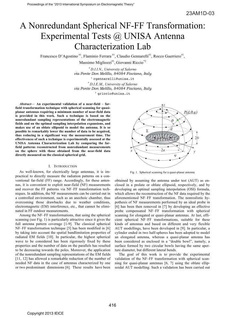
Among the NF–FF transformations, that using the spherical
scanning (see Fig. 1) is particularly attractive since it gives the
full antenna pattern coverage [1-9]. The classical spherical
NF–FF transformation technique [5] has been modified in [6]
by taking into account the spatial bandlimitation properties of
radiated EM fields [10]. In particular, the highest spherical
wave to be considered has been rigorously fixed by these
properties and the number of data on the parallels has resulted
to be decreasing towards the poles. Moreover, the application
of the nonredundant sampling representations of the EM fields
[11, 12] has allowed a remarkable reduction of the number of
needed NF data in the case of antennas characterized by one
or two predominant dimensions [6]. These results have been
��
��
�
��
���� � �
�
Fig. 1. Spherical scanning for a quasi-planar antenna
obtained by assuming the antenna under test (AUT) as en-
closed in a prolate or oblate ellipsoid, respectively, and by
developing an optimal sampling interpolation (OSI) formula,
which allows the reconstruction of the NF data required by the
aforementioned NF–FF transformation. The nonrealistic hy-
pothesis of NF measurements performed by an ideal probe in
[6] has been then removed in [7] by developing an effective
probe compensated NF–FF transformation with spherical
scanning for elongated or quasi-planar antennas. At last, effi-
cient spherical NF–FF transformations, suitable for these
kinds of antennas and based on different and very flexible
AUT modellings, have been developed in [9]. In particular, a
cylinder ended in two half-spheres has been adopted to model
an elongated antenna, whereas a quasi-planar antenna has
been considered as enclosed in a “double bowl”, namely, a
surface formed by two circular bowls having the same aper-
ture diameter, but different lateral bends.
The goal of this work is to provide the experimental
validation of the NF–FF transformation with spherical scan-
ning for quasi-planar antennas [6, 7] using the oblate ellip-
soidal AUT modelling. Such a validation has been carried out
Copyright 2013 IEICE
Proceedings of the "2013 International Symposium on Electromagnetic Theory"
23AM1D-03
416

at the antenna characterization laboratory of the University of
Salerno.
II. NONREDUNDANT SAMPLING REPRESENTATION OF THE
PROBE VOLTAGE ON A SPHERE
Let us consider a nondirective probe scanning a spherical
surface of radius d in the NF region of a quasi-planar antenna
enclosed in an oblate ellipsoid having major and minor
semi-axes equal to a and b, respectively. Moreover, let us
adopt the spherical coordinate system (r, , ) to denote an
observation point (see Fig. 1).
Since the voltage V measured by such a kind of probe has
the same effective spatial bandwidth of the field, the nonre-
dundant sampling representation of EM fields [11] can be ap-
plied to it. Inasmuch as a spherical surface can be represented
by meridians and parallels, in the following we deal with the
voltage representation on a curve C described by a parameteri-
zation r = r( ) . According to [11], let us introduce the “re-
duced voltage”
V ( ) =V ( ) e j ( )
(1)
where V ( ) is the voltage
V1 or
V2 measured by the probe or
by the rotated probe and ( ) is a proper phase function. The
error, occurring when V ( ) is approximated by a bandlimited
function, becomes negligible as the bandwidth exceeds the
critical value:
W =max w( )[ ]=max maxr '
d ( )
d
R , r '( ) (2)
where is the wavenumber,
r ' denotes the source point, and
R = r( ) r ' . In fact, it exhibits a step-like behaviour whose
transition occurs at W [10]. Accordingly, the bandlimitation
error can be effectively controlled by choosing a bandwidth
equal to
'W , where
' is an enlargement bandwidth factor
slightly greater than unity for an electrically large antenna.
When C is a meridian, by choosing W = '/2 ,
' = 4aE / 2 2( ) being the length of the ellipse
C ' (inter-
section curve between the meridian plane through the observa-
tion point P and ), we get the following expressions [6] for
the parameterization and phase function:
=2
E sin1u
2( )
E / 22( )
(3)
= a vv
21
v2 2
E cos1 1
2
v2 2
2 (4)
where
E i i( ) denotes the elliptic integral of second kind and
u = (r1 r2) / 2 f and
v = (r1+ r2) / 2a are the elliptic coordi-
nates, r1,2 being the distances from P to the foci of
C ' .
Moreover, = f /a is its eccentricity and 2f its focal distance.
The expression of the parameter in (3) is valid when the
angle belongs to the range [0, /2]. For from /2 to , it
results = –
', where
' is the parameterization value
corresponding to the point specified by the angle – . As
shown in [6, 11], the curves = const and = const are
ellipses and hyperbolas confocal to C ' (see Fig. 2).
= const
= const
z
2a
P
x
2f
r2
r1
C
F2F
1
2b
Fig. 2. Oblate ellipsoidal modelling: curves = const and = const
When C is a parallel, the phase function is constant and it
is convenient to choose the angle as parameter. The
corresponding bandwidth [6, 11] is
W ( ) = asin ( ) (5)
wherein
= sin 1u is the polar angle of the asymptote to the
hyperbola through P.
According to the above results, the reduced voltage at P on
the meridian at can be determined via the OSI expansion
V ( ),( ) = Vn,( ) G ,
n, , N, N"( )
n = n0
q+1
n0+q
(6)
where
n
0= Int [ ] is the index of the sample nearest (on
the left) to P, 2q is the number of retained intermediate
samples V
n,( ) ,
n= n ;
= 2 (2N"+ 1) (7)
N" = Int( N ') + 1 ;
N ' = Int ( 'W )+1 (8)
> 1 is an oversampling factor required to control the trun-
cation error [11], and
G ,
n, , N, N"( ) =
N n,( )D
N" n( ) (9)
Moreover,
DN " ( ) =
sin (2N"+1) / 2[ ](2N "+1) sin( / 2)
(10)
N,( ) =
TN
2cos2
/ 2( ) cos2
/ 2( ) 1
TN
2 cos2
/ 2( ) 1 (11)
Proceedings of the "2013 International Symposium on Electromagnetic Theory"
417

are the Dirichlet and Tschebyscheff sampling functions, re-
spectively, T
N( ) being the Tschebyscheff polynomial of
degree N = N" N ' and = q .
The intermediate samples V
n,( ) can be evaluated by
means of the following OSI formula
Vn,( ) = V
n,
m,n( )m = m
0p +1
m0+ p
G , m,n , ,Mn,Mn"( ) (12)
wherein
m
0= Int / n( ) , 2p is the retained samples num-
ber, V
n,
m,n( ) are the reduced voltage samples on the par-
allel fixed by n
, and
m,n= m n= 2 m/(2Mn"+1) ;
Mn"= Int Mn'( )+1 (13)
Mn
' = Int *W ( n)[ ] + 1 ; Mn= Mn" Mn' (14)
*= 1+ ( ' 1) sin (
n)[ ]
2/3 ;
= p n (15)
The variation of
* with in (15) is necessary to guaran-
tee a bandlimitation error constant with respect to [10].
By matching the OSI expansions along meridians and
parallels, the following two-dimensional OSI formula results
V ,( ) = G ,n, , N, N"( ){
n = n0 q+1
n0+q
Vn, m,n( )G , m,n , ,Mn,Mn"( )}
m=m0 p+1
m0+ p
(16)
By using such an expansion, it is possible to evaluate
accurately the probe and rotated probe voltages at any point
on the scanning sphere and, in particular, at the points needed
by the classical NF–FF transformation with spherical scanning
[5] as modified in [7, 9].
III. EXPERIMENTAL TESTS
The described NF–FF transformation has been experiment-
ally validated in the anechoic chamber available at the UNISA
Antenna Characterization Lab, originally equipped with an
advanced cylindrical NF measurement facility supplied by MI
Technologies, which has been employed to successfully per-
form the experimental validation of the innovative NF–FF
transformations with cylindrical [12-14] and helicoidal scan-
nings [15-18]. Such a NF facility has been recently enhanced
with a further rotating table which provides a roll axis, thus
making possible to perform the spherical and plane polar
scannings, as well as, the spherical and planar spiral ones. The
chamber, whose dimensions are 8m 5m 4m , is provided
with pyramidal absorbers ensuring a background noise lower
than – 40 dB. The amplitude and phase measurements are car-
ried out by means of a computer-controlled vectorial network
analyzer Anritsu. An open-ended WR90 rectangular wave-
guide is used as probe. The considered AUT is a MI-12-8.2
standard gain horn with aperture 19.4cm 14.4cm , located
on the plane z = 0 of the adopted reference system (Fig. 1) and
operating at 10 GHz. Such an AUT has been modelled as
enclosed in an oblate ellipsoid with a = 12.3 cm and b = 4.5
cm. The probe output voltages have been collected on a
sphere of radius d = 78.5 cm.
The amplitudes of the reconstructed voltages V1 and
V2
relevant to the meridians at = 0° and = 90°, respectively,
are compared in Figs. 3 and 4 with those directly measured on
the same meridians, to assess the effectiveness of the two-
dimensional OSI algorithm (16).
-60
-50
-40
-30
-20
-10
0
-180 -120 -60 0 60 120 180
Rel
ativ
e vo
ltage
am
plitu
de (
dB) p = q = 7
' = 1.30 = 1.20
(degrees)
Fig. 3. Amplitude of V1 on the meridian at = 0°. Solid line: measured.
Crosses: recovered from nonredundant NF data.
-60
-50
-40
-30
-20
-10
0
-180 -120 -60 0 60 120 180
Rel
ativ
e vo
ltage
am
plitu
de (
dB) p = q = 7
' = 1.30 = 1.20
(degrees)
Fig. 4. Amplitude of V
2 on the meridian at = 90°. Solid line: measured.
Crosses: recovered from nonredundant NF data.
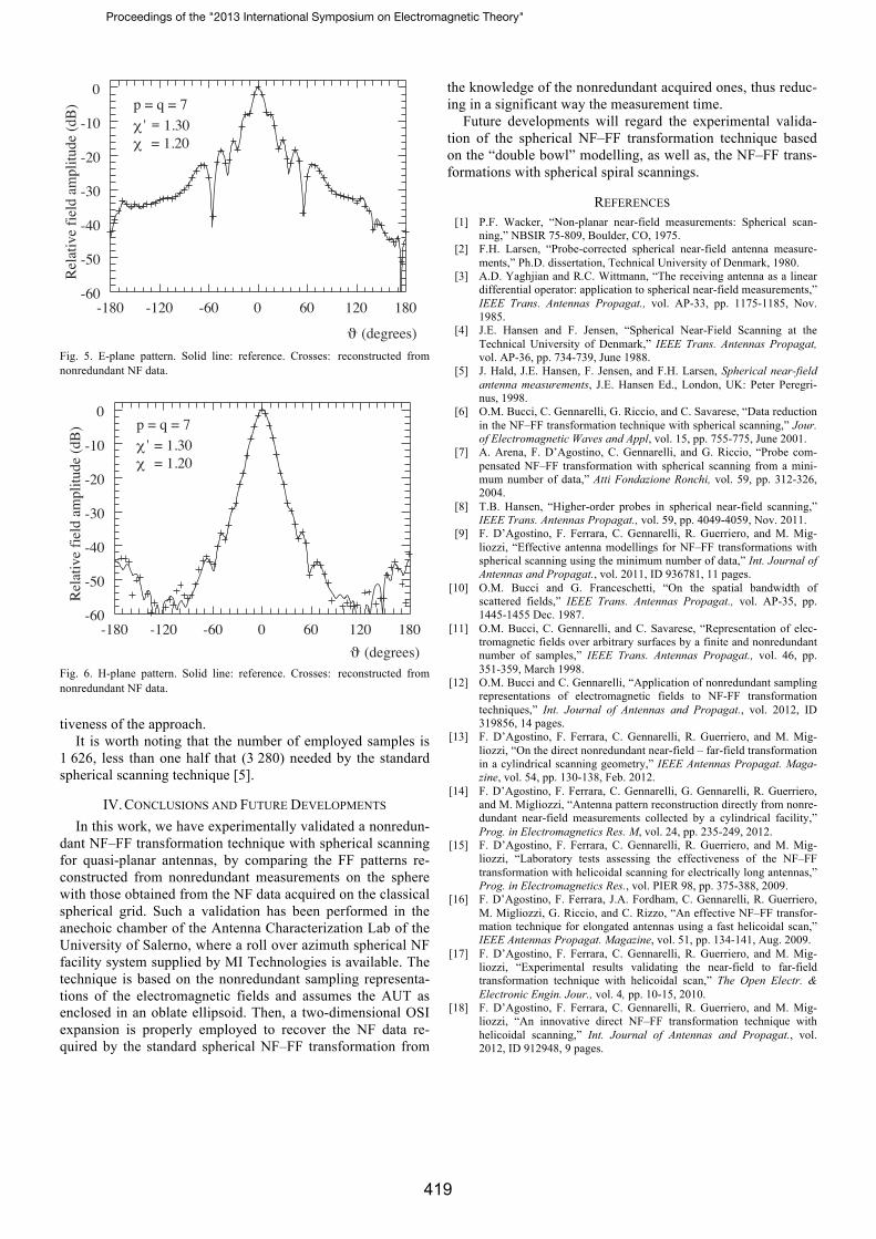
At last, the FF patterns in the principal planes E and H
obtained from the nonredundant spherical measurements are
compared in Figs. 5 and 6 with those (references) obtained
from the NF data directly measured on the classical spherical
grid. In both the cases, the software package MI-3000 has
been used to get the FF reconstructions. As can be seen, all
reconstructions are very accurate, thus confirming the effect-
Proceedings of the "2013 International Symposium on Electromagnetic Theory"
418
-60
-50
-40
-30
-20
-10
0
-180 -120 -60 0 60 120 180
Rel
ativ
e fi
eld
ampl
itude
(dB
) p = q = 7
' = 1.30 = 1.20
(degrees) Fig. 5. E-plane pattern. Solid line: reference. Crosses: reconstructed from
nonredundant NF data.
-60
-50
-40
-30
-20
-10
0
-180 -120 -60 0 60 120 180
Rel
ativ
e fi
eld
ampl
itude
(dB
) p = q = 7
' = 1.30 = 1.20
(degrees) Fig. 6. H-plane pattern. Solid line: reference. Crosses: reconstructed from
nonredundant NF data.
tiveness of the approach.
It is worth noting that the number of employed samples is
1 626, less than one half that (3 280) needed by the standard
spherical scanning technique [5].
IV. CONCLUSIONS AND FUTURE DEVELOPMENTS
In this work, we have experimentally validated a nonredun-
dant NF–FF transformation technique with spherical scanning
for quasi-planar antennas, by comparing the FF patterns re-
constructed from nonredundant measurements on the sphere
with those obtained from the NF data acquired on the classical
spherical grid. Such a validation has been performed in the
anechoic chamber of the Antenna Characterization Lab of the
University of Salerno, where a roll over azimuth spherical NF
facility system supplied by MI Technologies is available. The
technique is based on the nonredundant sampling representa-
tions of the electromagnetic fields and assumes the AUT as
enclosed in an oblate ellipsoid. Then, a two-dimensional OSI
expansion is properly employed to recover the NF data re-
quired by the standard spherical NF–FF transformation from
the knowledge of the nonredundant acquired ones, thus reduc-
ing in a significant way the measurement time.
Future developments will regard the experimental valida-
tion of the spherical NF–FF transformation technique based
on the “double bowl” modelling, as well as, the NF–FF trans-
formations with spherical spiral scannings.
REFERENCES
[1] P.F. Wacker, “Non-planar near-field measurements: Spherical scan-
ning,” NBSIR 75-809, Boulder, CO, 1975.
[2] F.H. Larsen, “Probe-corrected spherical near-field antenna measure-
ments,” Ph.D. dissertation, Technical University of Denmark, 1980.
[3] A.D. Yaghjian and R.C. Wittmann, “The receiving antenna as a linear
differential operator: application to spherical near-field measurements,”
IEEE Trans. Antennas Propagat., vol. AP-33, pp. 1175-1185, Nov.
1985.
[4] J.E. Hansen and F. Jensen, “Spherical Near-Field Scanning at the
Technical University of Denmark,” IEEE Trans. Antennas Propagat,
vol. AP-36, pp. 734-739, June 1988.
[5] J. Hald, J.E. Hansen, F. Jensen, and F.H. Larsen, Spherical near-field
antenna measurements, J.E. Hansen Ed., London, UK: Peter Peregri-
nus, 1998.
[6] O.M. Bucci, C. Gennarelli, G. Riccio, and C. Savarese, “Data reduction
in the NF–FF transformation technique with spherical scanning,” Jour.
of Electromagnetic Waves and Appl, vol. 15, pp. 755-775, June 2001.
[7] A. Arena, F. D’Agostino, C. Gennarelli, and G. Riccio, “Probe com-
pensated NF–FF transformation with spherical scanning from a mini-
mum number of data,” Atti Fondazione Ronchi, vol. 59, pp. 312-326,
2004.
[8] T.B. Hansen, “Higher-order probes in spherical near-field scanning,”
IEEE Trans. Antennas Propagat., vol. 59, pp. 4049-4059, Nov. 2011.
[9] F. D’Agostino, F. Ferrara, C. Gennarelli, R. Guerriero, and M. Mig-
liozzi, “Effective antenna modellings for NF–FF transformations with
spherical scanning using the minimum number of data,” Int. Journal of
Antennas and Propagat., vol. 2011, ID 936781, 11 pages.
[10] O.M. Bucci and G. Franceschetti, “On the spatial bandwidth of
scattered fields,” IEEE Trans. Antennas Propagat., vol. AP-35, pp.
1445-1455 Dec. 1987.
[11] O.M. Bucci, C. Gennarelli, and C. Savarese, “Representation of elec-
tromagnetic fields over arbitrary surfaces by a finite and nonredundant
number of samples,” IEEE Trans. Antennas Propagat., vol. 46, pp.
351-359, March 1998.
[12] O.M. Bucci and C. Gennarelli, “Application of nonredundant sampling
representations of electromagnetic fields to NF-FF transformation
techniques,” Int. Journal of Antennas and Propagat., vol. 2012, ID
319856, 14 pages.
[13] F. D’Agostino, F. Ferrara, C. Gennarelli, R. Guerriero, and M. Mig-
liozzi, “On the direct nonredundant near-field – far-field transformation
in a cylindrical scanning geometry,” IEEE Antennas Propagat. Maga-
zine, vol. 54, pp. 130-138, Feb. 2012.
[14] F. D’Agostino, F. Ferrara, C. Gennarelli, G. Gennarelli, R. Guerriero,
and M. Migliozzi, “Antenna pattern reconstruction directly from nonre-
dundant near-field measurements collected by a cylindrical facility,”
Prog. in Electromagnetics Res. M, vol. 24, pp. 235-249, 2012.
[15] F. D’Agostino, F. Ferrara, C. Gennarelli, R. Guerriero, and M. Mig-
liozzi, “Laboratory tests assessing the effectiveness of the NF–FF
transformation with helicoidal scanning for electrically long antennas,”
Prog. in Electromagnetics Res., vol. PIER 98, pp. 375-388, 2009.
[16] F. D’Agostino, F. Ferrara, J.A. Fordham, C. Gennarelli, R. Guerriero,
M. Migliozzi, G. Riccio, and C. Rizzo, “An effective NF–FF transfor-
mation technique for elongated antennas using a fast helicoidal scan,”
IEEE Antennas Propagat. Magazine, vol. 51, pp. 134-141, Aug. 2009.
[17] F. D’Agostino, F. Ferrara, C. Gennarelli, R. Guerriero, and M. Mig-
liozzi, “Experimental results validating the near-field to far-field
transformation technique with helicoidal scan,” The Open Electr. &
Electronic Engin. Jour., vol. 4, pp. 10-15, 2010.
[18] F. D’Agostino, F. Ferrara, C. Gennarelli, R. Guerriero, and M. Mig-
liozzi, “An innovative direct NF–FF transformation technique with
helicoidal scanning,” Int. Journal of Antennas and Propagat., vol.
2012, ID 912948, 9 pages.
Proceedings of the "2013 International Symposium on Electromagnetic Theory"
419