Embed Size (px)
Citation preview
Asian Journal of Science and Applied Technology ISSN: 2249-0698 Vol. 4 No. 1, 2015, pp.26-31
© The Research Publication, www.trp.org.in
A Novel Approach for Prediction of Bulging in the type A Dissected Aorta Using MIMICS Tool
K.Pradeep1 , M.Priyanga2, S.Vanisri3 and K.P.Pooja Udayan4
1Assistant professor, 2,3,4Dhanalakshmi Srinivasan Engineering College, Perambalur, Tamil Nadu, India E-mail: [email protected]
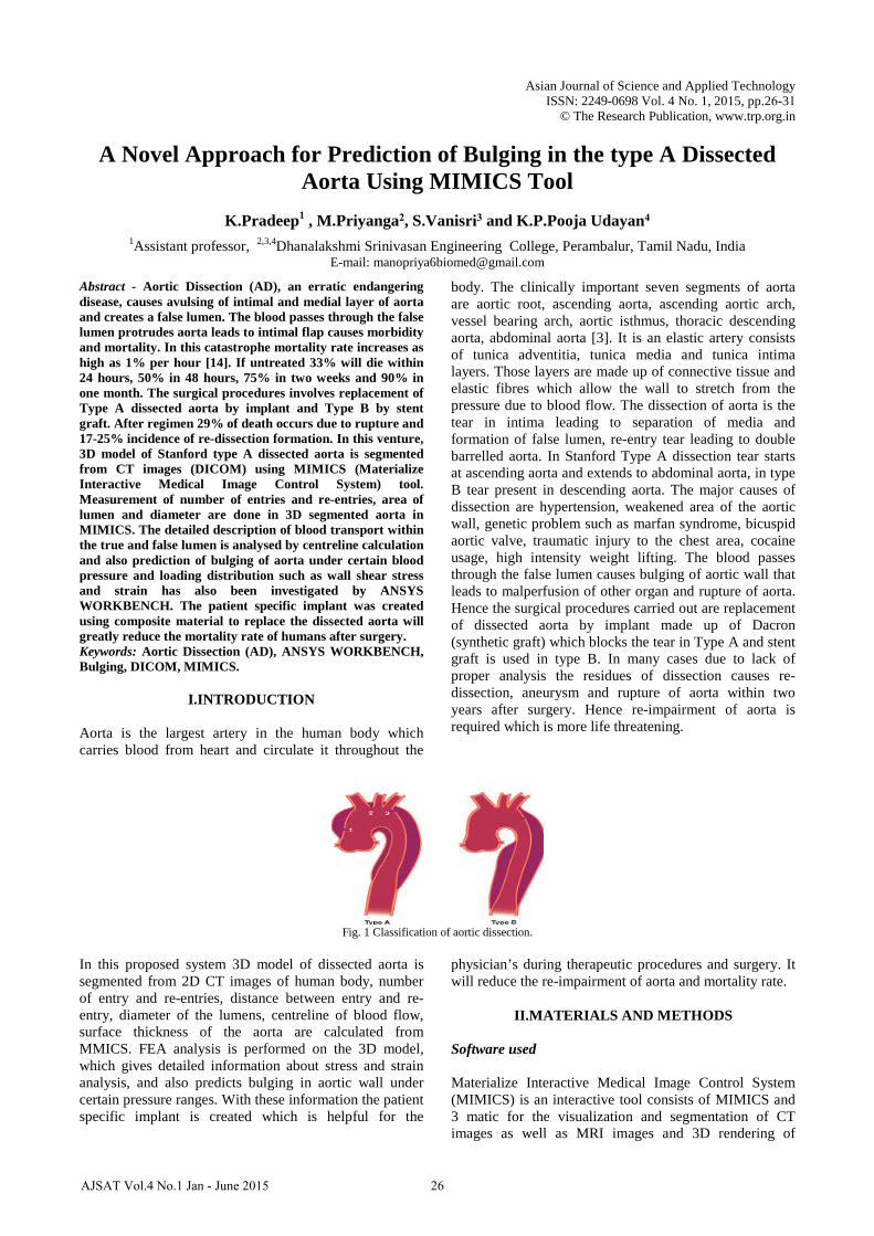
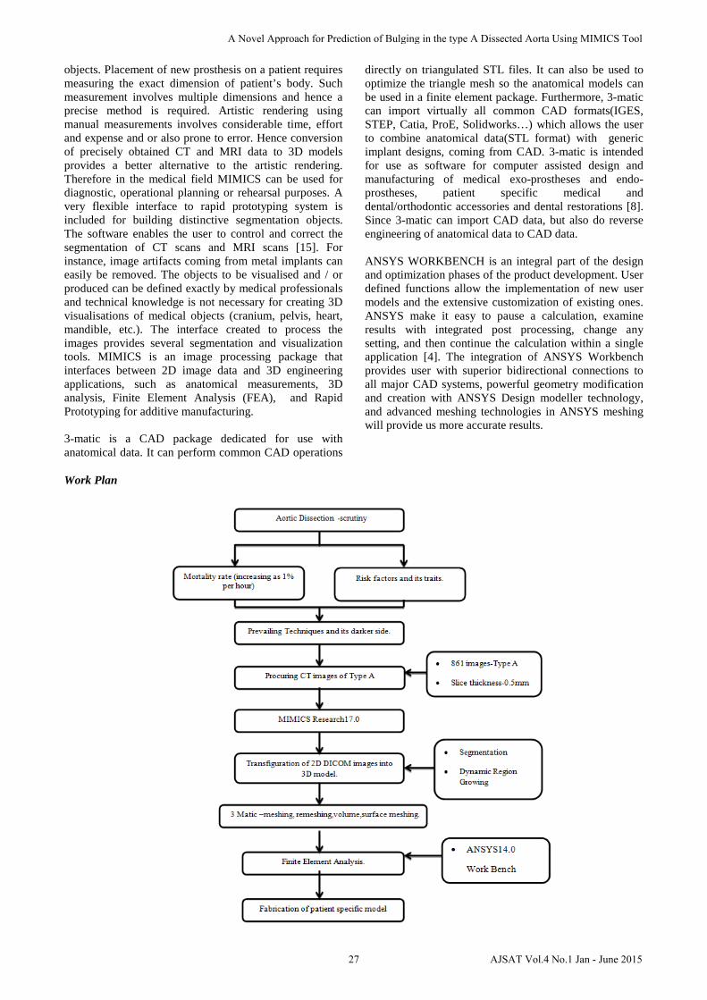
Abstract - Aortic Dissection (AD), an erratic endangering disease, causes avulsing of intimal and medial layer of aorta and creates a false lumen. The blood passes through the false lumen protrudes aorta leads to intimal flap causes morbidity and mortality. In this catastrophe mortality rate increases as high as 1% per hour [14]. If untreated 33% will die within 24 hours, 50% in 48 hours, 75% in two weeks and 90% in one month. The surgical procedures involves replacement of Type A dissected aorta by implant and Type B by stent graft. After regimen 29% of death occurs due to rupture and 17-25% incidence of re-dissection formation. In this venture, 3D model of Stanford type A dissected aorta is segmented from CT images (DICOM) using MIMICS (Materialize Interactive Medical Image Control System) tool. Measurement of number of entries and re-entries, area of lumen and diameter are done in 3D segmented aorta in MIMICS. The detailed description of blood transport within the true and false lumen is analysed by centreline calculation and also prediction of bulging of aorta under certain blood pressure and loading distribution such as wall shear stress and strain has also been investigated by ANSYS WORKBENCH. The patient specific implant was created using composite material to replace the dissected aorta will greatly reduce the mortality rate of humans after surgery. Keywords: Aortic Dissection (AD), ANSYS WORKBENCH, Bulging, DICOM, MIMICS.
I.INTRODUCTION
Aorta is the largest artery in the human body which carries blood from heart and circulate it throughout the
body. The clinically important seven segments of aorta are aortic root, ascending aorta, ascending aortic arch, vessel bearing arch, aortic isthmus, thoracic descending aorta, abdominal aorta [3]. It is an elastic artery consists of tunica adventitia, tunica media and tunica intima layers. Those layers are made up of connective tissue and elastic fibres which allow the wall to stretch from the pressure due to blood flow. The dissection of aorta is the tear in intima leading to separation of media and formation of false lumen, re-entry tear leading to double barrelled aorta. In Stanford Type A dissection tear starts at ascending aorta and extends to abdominal aorta, in type B tear present in descending aorta. The major causes of dissection are hypertension, weakened area of the aortic wall, genetic problem such as marfan syndrome, bicuspid aortic valve, traumatic injury to the chest area, cocaine usage, high intensity weight lifting. The blood passes through the false lumen causes bulging of aortic wall that leads to malperfusion of other organ and rupture of aorta. Hence the surgical procedures carried out are replacement of dissected aorta by implant made up of Dacron (synthetic graft) which blocks the tear in Type A and stent graft is used in type B. In many cases due to lack of proper analysis the residues of dissection causes re-dissection, aneurysm and rupture of aorta within two years after surgery. Hence re-impairment of aorta is required which is more life threatening.
Fig. 1 Classification of aortic dissection.
In this proposed system 3D model of dissected aorta is segmented from 2D CT images of human body, number of entry and re-entries, distance between entry and re-entry, diameter of the lumens, centreline of blood flow, surface thickness of the aorta are calculated from MMICS. FEA analysis is performed on the 3D model, which gives detailed information about stress and strain analysis, and also predicts bulging in aortic wall under certain pressure ranges. With these information the patient specific implant is created which is helpful for the
physician’s during therapeutic procedures and surgery. It will reduce the re-impairment of aorta and mortality rate.
II.MATERIALS AND METHODS
Software used
Materialize Interactive Medical Image Control System (MIMICS) is an interactive tool consists of MIMICS and 3 matic for the visualization and segmentation of CT images as well as MRI images and 3D rendering of
26AJSAT Vol.4 No.1 Jan - June 2015
objects. Placement of new prosthesis on a patient requires measuring the exact dimension of patient’s body. Such measurement involves multiple dimensions and hence a precise method is required. Artistic rendering using manual measurements involves considerable time, effort and expense and or also prone to error. Hence conversion of precisely obtained CT and MRI data to 3D models provides a better alternative to the artistic rendering. Therefore in the medical field MIMICS can be used for diagnostic, operational planning or rehearsal purposes. A very flexible interface to rapid prototyping system is included for building distinctive segmentation objects. The software enables the user to control and correct the segmentation of CT scans and MRI scans [15]. For instance, image artifacts coming from metal implants can easily be removed. The objects to be visualised and / or produced can be defined exactly by medical professionals and technical knowledge is not necessary for creating 3D visualisations of medical objects (cranium, pelvis, heart, mandible, etc.). The interface created to process the images provides several segmentation and visualization tools. MIMICS is an image processing package that interfaces between 2D image data and 3D engineering applications, such as anatomical measurements, 3D analysis, Finite Element Analysis (FEA), and Rapid Prototyping for additive manufacturing.
3-matic is a CAD package dedicated for use withanatomical data. It can perform common CAD operations
directly on triangulated STL files. It can also be used to optimize the triangle mesh so the anatomical models can be used in a finite element package. Furthermore, 3-matic can import virtually all common CAD formats(IGES, STEP, Catia, ProE, Solidworks…) which allows the user to combine anatomical data(STL format) with generic implant designs, coming from CAD. 3-matic is intended for use as software for computer assisted design and manufacturing of medical exo-prostheses and endo-prostheses, patient specific medical and dental/orthodontic accessories and dental restorations [8]. Since 3-matic can import CAD data, but also do reverse engineering of anatomical data to CAD data.
ANSYS WORKBENCH is an integral part of the design and optimization phases of the product development. User defined functions allow the implementation of new user models and the extensive customization of existing ones. ANSYS make it easy to pause a calculation, examine results with integrated post processing, change any setting, and then continue the calculation within a single application [4]. The integration of ANSYS Workbench provides user with superior bidirectional connections to all major CAD systems, powerful geometry modification and creation with ANSYS Design modeller technology, and advanced meshing technologies in ANSYS meshing will provide us more accurate results.
Work Plan
27
A Novel Approach for Prediction of Bulging in the type A Dissected Aorta Using MIMICS Tool
AJSAT Vol.4 No.1 Jan - June 2015

3D modelling methodology in MIMICS
MIMICS (Materialise Interactive Medical Image Control System) is a material software for processing DICOM images and to create 3D model from 2D Computed Tomography and Magnetic Resonance images.It allows us to create a STL ,VRML,IGES file formats which can be exported to some other software packages like Finite Element Analysis and Computational Fluid Dynamics for
testing and analysing. The tomographic images of the cardiac routine (adult) aortagram from the scanning modalities (software version: syngo CT 2011) are stacked based on slice thickness, reconstruction diameter and this consists of images in XY plane (axial plane). The 3D calculation involves creation of images in the XZ (coronal) and YZ (sagittal) directions.The imported series here is CorCTA 2.0 B30f BestDiast 71% consists of 861 slices with the thickness 0.5mm.
Fig 2: Stacking of CT images.
The key to converting anatomical data from images to 3D model is a process called Segmentation. Based on the absorption coefficients of various tissues, the images which consist of grayscale values are achieved in the CT and MRI scans. These grayscale values are utilized inorder to recreate 3D model from the CT data. By categorizing the similar grayscale values image data can be segmented and thus the model of dissected aorta are segmented. Dynamic Region Growing is a segmenting tool which is put to use for segmenting the soft tissues without use of thresholding by assigning user grayscale values. Here, aorta can be segmented by fixing deviation as 80-150 GV with fill cavities and multiple layers. It is
extremely useful for vessels, arteries and nerves.The Region Growing process allows splitting the aorta in particular from the whole softtissue model in different and separated parts, corresponding each part to one mask that can be distinguished by the different applied mask’s colour. The final step in 3D model generation is to calculate and build up the mask image layers. The accuracy of the created 3D model falls on the original scanned data. The region of interest is selected by region growing and 3D image is calculated by masking the undesired data.The accuracy in the MIMICS model matches the accuracy of an object captured within the scan.
Fig. 3 3D segmentation of dissected aorta
28
K.Pradeep , M.Priyanga, S.Vanisri and K.P.Pooja Udayan
AJSAT Vol.4 No.1 Jan - June 2015
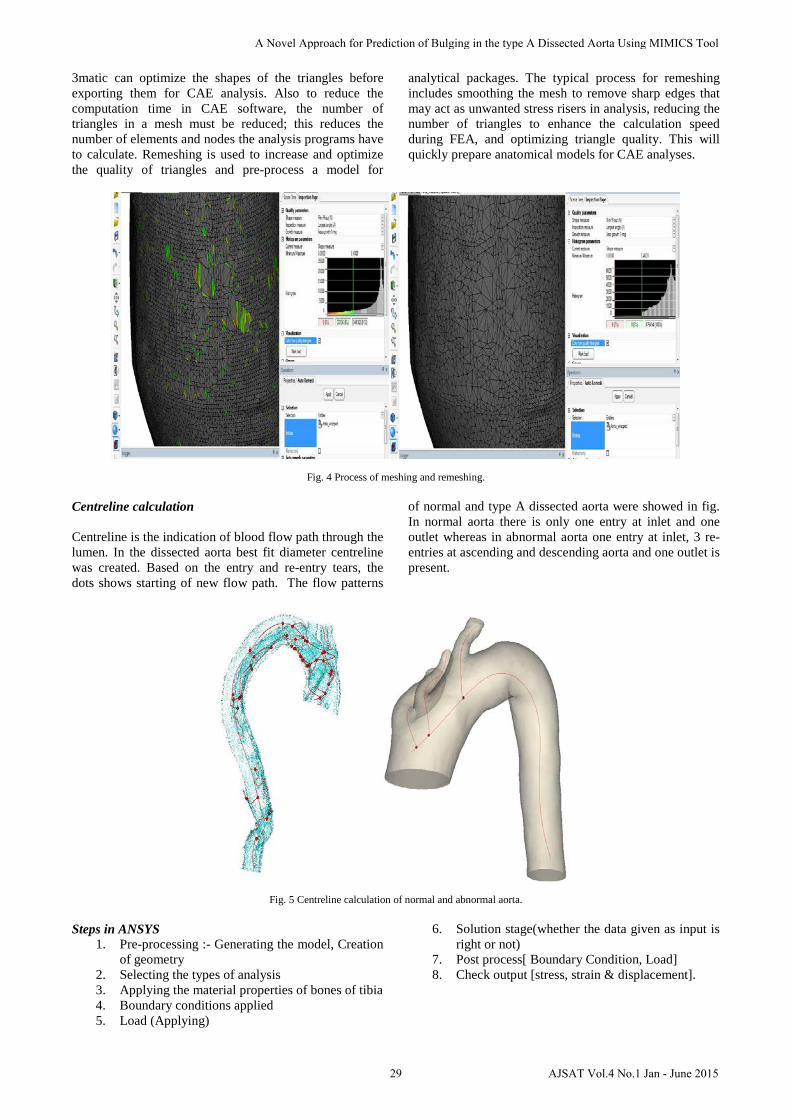
3matic can optimize the shapes of the triangles before exporting them for CAE analysis. Also to reduce the computation time in CAE software, the number of triangles in a mesh must be reduced; this reduces the number of elements and nodes the analysis programs have to calculate. Remeshing is used to increase and optimize the quality of triangles and pre-process a model for
analytical packages. The typical process for remeshing includes smoothing the mesh to remove sharp edges that may act as unwanted stress risers in analysis, reducing the number of triangles to enhance the calculation speed during FEA, and optimizing triangle quality. This will quickly prepare anatomical models for CAE analyses.
Fig. 4 Process of meshing and remeshing.
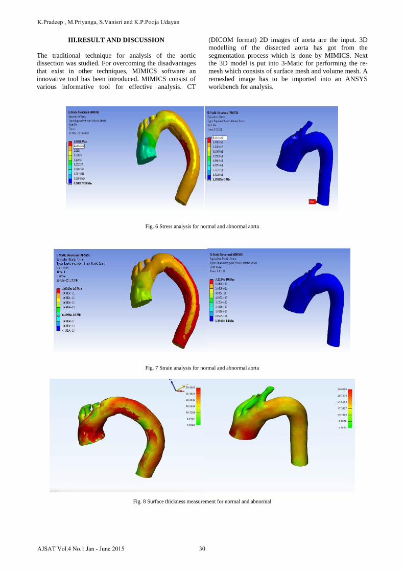
Centreline calculation
Centreline is the indication of blood flow path through the lumen. In the dissected aorta best fit diameter centreline was created. Based on the entry and re-entry tears, the dots shows starting of new flow path. The flow patterns
of normal and type A dissected aorta were showed in fig. In normal aorta there is only one entry at inlet and one outlet whereas in abnormal aorta one entry at inlet, 3 re-entries at ascending and descending aorta and one outlet is present.
Fig. 5 Centreline calculation of normal and abnormal aorta.
Steps in ANSYS 1. Pre-processing :- Generating the model, Creation
of geometry2. Selecting the types of analysis3. Applying the material properties of bones of tibia4. Boundary conditions applied5. Load (Applying)
6. Solution stage(whether the data given as input isright or not)
7. Post process[ Boundary Condition, Load]8. Check output [stress, strain & displacement].
29
A Novel Approach for Prediction of Bulging in the type A Dissected Aorta Using MIMICS Tool
AJSAT Vol.4 No.1 Jan - June 2015
III.RESULT AND DISCUSSION
The traditional technique for analysis of the aortic dissection was studied. For overcoming the disadvantages that exist in other techniques, MIMICS software an innovative tool has been introduced. MIMICS consist of various informative tool for effective analysis. CT
(DICOM format) 2D images of aorta are the input. 3D modelling of the dissected aorta has got from the segmentation process which is done by MIMICS. Next the 3D model is put into 3-Matic for performing the re-mesh which consists of surface mesh and volume mesh. A remeshed image has to be imported into an ANSYS workbench for analysis.
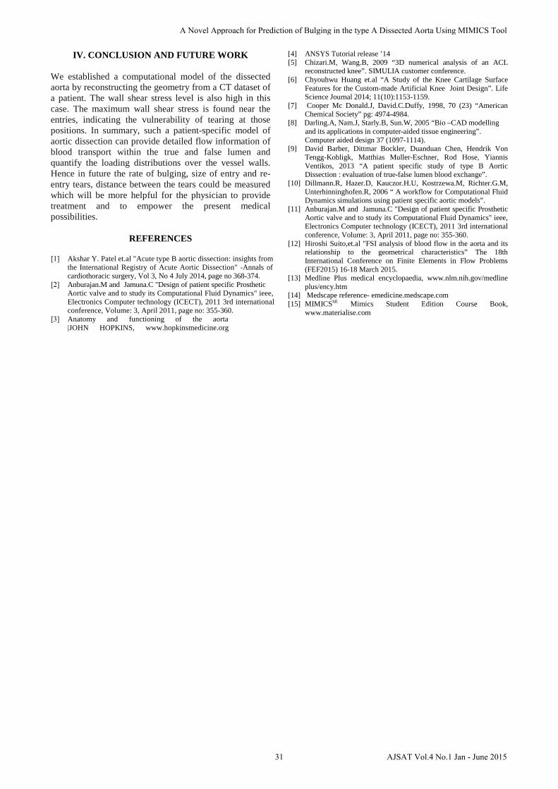
Fig. 6 Stress analysis for normal and abnormal aorta
Fig. 7 Strain analysis for normal and abnormal aorta
Fig. 8 Surface thickness measurement for normal and abnormal
30
K.Pradeep , M.Priyanga, S.Vanisri and K.P.Pooja Udayan
AJSAT Vol.4 No.1 Jan - June 2015
IV. CONCLUSION AND FUTURE WORK
We established a computational model of the dissected aorta by reconstructing the geometry from a CT dataset of a patient. The wall shear stress level is also high in this case. The maximum wall shear stress is found near the entries, indicating the vulnerability of tearing at those positions. In summary, such a patient-specific model of aortic dissection can provide detailed flow information of blood transport within the true and false lumen and quantify the loading distributions over the vessel walls. Hence in future the rate of bulging, size of entry and re-entry tears, distance between the tears could be measured which will be more helpful for the physician to provide treatment and to empower the present medical possibilities.
REFERENCES
[1] Akshar Y. Patel et.al "Acute type B aortic dissection: insights fromthe International Registry of Acute Aortic Dissection" -Annals of cardiothoracic surgery, Vol 3, No 4 July 2014, page no 368-374.
[2] Anburajan.M and Jamuna.C "Design of patient specific ProstheticAortic valve and to study its Computational Fluid Dynamics" ieee,Electronics Computer technology (ICECT), 2011 3rd internationalconference, Volume: 3, April 2011, page no: 355-360.
[3] Anatomy and functioning of the aorta|JOHN HOPKINS, www.hopkinsmedicine.org
[4] ANSYS Tutorial release ’14[5] Chizari.M, Wang.B, 2009 “3D numerical analysis of an ACL
reconstructed knee”. SIMULIA customer conference.[6] Chyouhwu Huang et.al “A Study of the Knee Cartilage Surface
Features for the Custom-made Artificial Knee Joint Design”. LifeScience Journal 2014; 11(10):1153-1159.
[7] Cooper Mc Donald.J, David.C.Duffy, 1998, 70 (23) “AmericanChemical Society” pg: 4974-4984.
[8] Darling.A, Nam.J, Starly.B, Sun.W, 2005 “Bio –CAD modelling and its applications in computer-aided tissue engineering”. Computer aided design 37 (1097-1114).
[9] David Barber, Dittmar Bockler, Duanduan Chen, Hendrik VonTengg-Kobligk, Matthias Muller-Eschner, Rod Hose, YiannisVentikos, 2013 “A patient specific study of type B AorticDissection : evaluation of true-false lumen blood exchange”.
[10] Dillmann.R, Hazer.D, Kauczor.H.U, Kostrzewa.M, Richter.G.M,Unterhinninghofen.R, 2006 “ A workflow for Computational FluidDynamics simulations using patient specific aortic models”.
[11] Anburajan.M and Jamuna.C "Design of patient specific ProstheticAortic valve and to study its Computational Fluid Dynamics" ieee,Electronics Computer technology (ICECT), 2011 3rd internationalconference, Volume: 3, April 2011, page no: 355-360.
[12] Hiroshi Suito,et.al "FSI analysis of blood flow in the aorta and itsrelationship to the geometrical characteristics” The 18thInternational Conference on Finite Elements in Flow Problems(FEF2015) 16-18 March 2015.
[13] Medline Plus medical encyclopaedia, www.nlm.nih.gov/medlineplus/ency.htm
[14] Medscape reference- emedicine.medscape.com [15] MIMICSSE Mimics Student Edition Course Book,
www.materialise.com
31
A Novel Approach for Prediction of Bulging in the type A Dissected Aorta Using MIMICS Tool
AJSAT Vol.4 No.1 Jan - June 2015