Embed Size (px)
Citation preview

15CVL– 38 Surveying practice-I
Dept. of CIVIL Engg, CIT, Gubbi- 572 216 Page 1
SURVEYOR
BPA
Fig. 1.1 Direct ranging

15CVL– 38 Surveying practice-I
Dept. of CIVIL Engg, CIT, Gubbi- 572 216 Page 2
Experiment No. 1 Date: __ /__ / __
MEASUREMENT OF DISTANCE
Exercise : 1.1
Case 1: Horizontal plane
Aim:To measure distance between two points using direct ranging (Fig. 1.1)
Instruments used:
Theory: Measurement of distance between two points, which are at a large distance , involves two
steps namely ranging and chaining. Ranging is a process of locating points on a given straight line.
There are two methods of ranging, namely direct ranging and indirect ranging. Direct ranging may be
done with eye judgment or by using instrument like line ranger.
Chaining is a process of measuring a distance either by a chain or a tape.
Procedure:
Let A and B be the two points at the ends of a survey line. One ranging rod is erected at the B while
surveyor stands with another ranging rod at point A. The assistant then goes with another ranging rod
and establishes the rod at a point approximately in the line with AB at a distance not greater than one
chain length from A. Surveyor at A signals the assistant to move transverse to the chain line, till he is
in line with A and B. Similarly, other intermediate points can be established. Now measure the distance
between the points A and B.
RESULTS:-
Sl.
No. Particulars Quantity
1. Chain 01
2. Tape 01
3. Ranging Rods 03
3. Arrows Few

15CVL– 38 Surveying practice-I
Dept. of CIVIL Engg, CIT, Gubbi- 572 216 Page 3
lPlumb bob
D1
D2
D3
D4
L
Fig. 1.2Indirect ranging (Stepping method)
L = D1+D2 + D3+D4
Where, L = Total horizontal distance
D = horizontal distances between the intervals

15CVL– 38 Surveying practice-I
Dept. of CIVIL Engg, CIT, Gubbi- 572 216 Page 4
Case 2: Sloping ground
Aim:To measure distance between two points using direct ranging (Fig. 1.2)
Instruments used:
Theory:
Procedure:
RESULTS:-
Sl.
No. Particulars Quantity
1. Chain 01
2. Tape 01
3. Ranging Rods 03
3. Arrows Few
15CVL– 38 Surveying practice-I
Dept. of CIVIL Engg, CIT, Gubbi- 572 216 Page 5
Fig. 1.3 First method (3-4-5 method)
A
4 m
3 m
E C
5 m
0
B
10
D1 m
LOOP

15CVL– 38 Surveying practice-I
Dept. of CIVIL Engg, CIT, Gubbi- 572 216 Page 6
Date: __ /__ / __
ERECTION OF PERPENDICULAR
Exercise : 1.2
Aim: To erect perpendicular from a given chain line to a given point using chain and tape only.
Instruments used:
Procedure:
Let AB be the given chain line and C be the given point on AB at which it is desired to erect a
perpendicular.
First method (3-4-5 method) :( Fig 1.3)
1. Establish a point E at distance of 3m from C.
2. Put the zero end of the tape at E and the 10m end at C.
3. The 5m and 6m marks are brought together to form a loop of 1m.
4. Fastening the ends E and C stretch the tape tightly.
5. The point D is thus established.
6. Join DC, and point D gives the position of the perpendicular CD at C on the
chain line AB.
Sl.
No. Particulars Quantity
1. Chain 01
2. Tape 01
3. Ranging Rods 03
3. Arrows few

15CVL– 38 Surveying practice-I
Dept. of CIVIL Engg, CIT, Gubbi- 572 216 Page 7
Fig.1.3Second method
Fig. 1.4 Third method
A E FC B
D
A
F
E C B
D

15CVL– 38 Surveying practice-I
Dept. of CIVIL Engg, CIT, Gubbi- 572 216 Page 8
Second method: (Fig 1.4)
1. Select E and F equidistant from C.
2. Hold zero end of the tape at E and hold the 10 m end at F.
3. Pick up 5 m mark, stretch the tape tight and establish D.
4. Join DC, and point D gives the position of the perpendicular CD at C on the
chain line AB.
Third method: (Fig 1.5)
1. Select any point F out side the chain, preferably at 5 m distance from C.
2. Hold the 5 m mark at F and zero end of the tape at C, with F as center draw an
arc to cut the chain line at E.
3. Join EF and produce it to D such that EF = FD = 5 m.
4. Thus, point D will lie at the 10 m mark of the tape laid along EF with its zero
end at E.
5. Join DC, and point D gives the position of the perpendicular CD at C on the
chain line AB.
Results:

15CVL– 38 Surveying practice-I
Dept. of CIVIL Engg, CIT, Gubbi- 572 216 Page 9
Fig. 1.5 Cross – Staff
A
CROSS STAFF
C B
D

15CVL– 38 Surveying practice-I
Dept. of CIVIL Engg, CIT, Gubbi- 572 216 Page 10
Exercise 1.3 Date: __ /__ / __
Aim: To erect perpendicular from a given chain line to a given point using Cross - Staff.
Instruments used:
Theory: Cross staff consists of a wooden block of about 150mm square and about 35mm thick. The
block has on its top surface, two grooves or slits at perpendicular to each other. The grooves are about
10mm deep. The wooden block is fixed at the top of a vertical pole or rod
Procedure:(Fig 1.4)
Let AB be the given chain line and C be the given point on AB at which it is desired to erect a
perpendicular Erect ranging rods at both the ends of the chain line AB.
The cross - staff is set up at a point C on the chain line from which the perpendicular is to erect.
Now cross - staff is then turned until one line of sight posses through the ranging rod at the end of the
chain line.
The line of sight through the other two vanes will be a line at right angles to the chain line AB and a
ranging rod may be established in that direction at D.
Join C and D. CD will be the perpendicular to the chain line AB.
Results:
Sl.
No. Particulars Quantity
1. Chain 01
2. Tape 01
3. Ranging Rods 03
3. Arrows few

15CVL– 38 Surveying practice-I
Dept. of CIVIL Engg, CIT, Gubbi- 572 216 Page 11
Fig. 1.6 Optical square
FROM, QE
FROM
P
F
D B G
A
C

15CVL– 38 Surveying practice-I
Dept. of CIVIL Engg, CIT, Gubbi- 572 216 Page 12
Exercise –1.4 Date: __ /__ / __
Aim: To erect perpendicular from a given chain line to a given point using Optical square.
Instruments used:
Theory: Optical Square is a compact instrument used for setting out perpendicular to the chain line. It
consists of a horizon glass H, which is half silvered and half unsilvered and an index glass which is fully
silvered. These two glasses are placed at an angle 45° inside the circular box .The box has three
openings .One is circular for eye and the other diametrically opposite to this is rectangular is located
perpendicular to the line of sight. Fig shows sectional plan of optical square. The optical square works
on the following principal.
“If a ray of light undergoes two successive reflections, the angle between the incident ray
and the last reflected ray is twice the angle between the mirrors”
In the optical square, as the angle between the mirrors is 45°, the last reflected ray is perpendicular to
the incident ray
Procedure: (Fig 1.7)Let AB be the given chain line and C be the given point on AB at which it is
desired to erect a perpendicular.
1. To set a right angle on a chain line AB the instrument is held on the line with its center on the
point C at which perpendicular is erected.
2. The slits F and G are directed towards the ranging rod fixed at the end of the chain line.
3. The surveyor (holding the instrument) then directs the person, holding a ranging rod and
stationing in a direction roughly perpendicular to the chain line to move till the two images
coincide.
Results:
Sl.
No. Particulars Quantity
1. Chain 01
2. Tape 01
3. Ranging Rods 02
3. Arrows few
4. Optical square 01

15CVL– 38 Surveying practice-I
Dept. of CIVIL Engg, CIT, Gubbi- 572 216 Page 13
Fig. 2.1Reciprocal ranging
Fig. 2.2Randomline
15CVL– 38 Surveying practice-I
Dept. of CIVIL Engg, CIT, Gubbi- 572 216 Page 14
Experiment No. 2 Date: __ /__ / __
OBSTACLES IN CHAINING AND RANGING
AIM: To measure distance between two points by chaining across different types of Obstacles
encountered by indirect method.
APPARATUS: Chain, tape, cross-staff , ranging rods, arrows.
PROCEDURE: Obstacles to chaining prevent chainmen to measuring directly between Two points and
give rise to a set of problems in which distances are found by indirect Measurements. Obstacles to
chaining are of three kinds.
1. Obstacles to ranging but not chaining. E.x (High level ground)
2. Obstacles to chaining but not ranging. E.x(Pond,river)
3. Obstacles to both chaining and ranging. E.x(building)
I) OBSTACLES TO RANGING BUT NOT CHAINING;-
This type of problem comes, when a rising ground or a forest area interrupts the chain line. The
end station are not inter visible
There may two cases of this obstacle.
1. Both ends of line may be visible from intermediate points on line.
2. Both ends of line may not be visible from intermediate points on line.
Case-1: Both the stations are visible from intermediate points on the line (reciprocal
ranging)
1. In this case reciprocal ranging is adopted and chaining is done by stepping method
2. A and B are two end stations, which are not inter visible due to a hill in between them.
3. Select two intermediate points P1 and Q1, such that from each station point A and B are visible.
4. Two persons take up the positions P1 and Qlwith ranging rods.
5. First the person standing at Pl directs the person at Qlto come in line of Pl B, and his new
position will be Q2.
6. Now, the person standing at Q2, directs the person at pi, to come in line of Q2 A, and his new
position will be P2.

15CVL– 38 Surveying practice-I
Dept. of CIVIL Engg, CIT, Gubbi- 572 216 Page 15
Fig. 3.3Method (a)
Fig. 2.4 Method (b)
Fig. 2.5Method (c)
15CVL– 38 Surveying practice-I
Dept. of CIVIL Engg, CIT, Gubbi- 572 216 Page 16
7. Now, the person standing at P2, directs the person at Q2, to come in line of P2 B, and his new
position will be Q3.
8. This process is continued until the intermediate points P and Q are located in such a way that
the person standing at P, see Q and B in the line, and the person standing at Q, see P and A in
the line.
9. Distance AB = AP+PQ+QB
Case-2: The end stations are not visible from the intermediate points on the line. This is the case when
trees, bushes or jungle comes across the chain line. In this case the method of random line is most
suitable.
1. In fig let PQ be the line in which P and Q are not visible from intermediate Point on it.
2. Through P draw a random line PQ in any convenient direction but as nearly to Towards Q as
possible.
3. The points Q should be so chosen that, Q1 is visible from Q and Q,Q1 is in random Line.
4. Measure QQ1 select points S1 and R1 on random line and erect perpendicular SS1 and RR1
on it.
5. Make SS1= PS1/PQ1 x QQ1 And RR1= PR1/PQ1 x QQ1
6. Join SR and prolong.
II) OBSTACLES TO CHAINING BUT NOT RANGING:-
There may be two cases of this obstacle.
1. When it is possible to chain round the obstacle. i.e. A POND.
2. When it is not possible to chain round the obstacle. i.e. A RIVER.
CASE1:Following are the methods.
Method (a):
1. Select two points A AND B on either side
2. Set out equal perpendicular AC and BD as shown in fig (a)
3. Measure CD=AB.

15CVL– 38 Surveying practice-I
Dept. of CIVIL Engg, CIT, Gubbi- 572 216 Page 17
Fig. 2.6Method (d)
Fig. 2.7Method (e)

15CVL– 38 Surveying practice-I
Dept. of CIVIL Engg, CIT, Gubbi- 572 216 Page 18
Method (b):
1. Set out AC perpendicular to chain line as shown in fig (b)
2. Measure AC and BC
3. The length AB is calculated from the relation
AB=√BC²-AC²
Method (c):
1. By cross staff find a point C .which subtends 90° with A and B as shown in fig (C). AC and BC.
2. The length AB is calculated from relation AB= √AC²+BC².
Method (d):
1. select any point E and range C in line with AE, making AE =EC
2. Range D in line with BE and make BE=ED as shown in fig (d).
3. Measure CD then AB=CD.
CASE2: Following are the methods.
Method (e)
1. Select point B on one side and A and C on the other side.
2. Erect AD and CE as perpendicular to AB and range B,D and E in One line as shown in fig (e).
3. Measure AC, AD and CE.
4. If a line DF is drawn parallel to AB cutting CE in F perpendicularly The triangle ABD and FDE will
be similar.

15CVL– 38 Surveying practice-I
Dept. of CIVIL Engg, CIT, Gubbi- 572 216 Page 19
Fig. 2.8 Method (f)
Fig. 2.9 Method (g)

15CVL– 38 Surveying practice-I
Dept. of CIVIL Engg, CIT, Gubbi- 572 216 Page 20
Method (f):
1. Locate a point R in such a way that it makes 900 with PQ.
2. Range S in line with PR and make PS = PR.
3. At S erect a perpendicular ST to cut the line AB at T.
4. Then PQ =PT.
III) OBSTACLES TO BOTH CHAINING AND RANGING;-
A Building is the typical example of this type of obstacles. The problem lies In prolonging the line
beyond the obstacle and determine the distance across it.
Method (g);
1. Choose two points A and B to one side erect perpendicular AC and BD of equal length.
2. Join CD and prolong It pass the obstacles.
3. Choose two points E and F on CD and erect perpendicular EG and FH equal to AC or BD as
shown in fig (g).
4. Join GH and prolong it. Measure DE.
5. BG=DE.
Method (h):
1. Select a point A and erect a perpendicular AC of any convenient Length.
2. Select another point B on chain line such that AB=AC.
3. Join B and C and prolong it. To any convenient point D.
4. At D set a right angle DE such that DE=DB.
5. Choose another point F on DE such that DF=DC with F as centre and AB as radius. Draw an arc
with E as center draw another arc of same Radius to cut previous arc in G
6. Join GE which will be in range with chain line. Refer the fig (h)
7. Measure CF then AG=CF.

15CVL– 38 Surveying practice-I
Dept. of CIVIL Engg, CIT, Gubbi- 572 216 Page 21
Fig. 2.10 Method (h)

15CVL– 38 Surveying practice-I
Dept. of CIVIL Engg, CIT, Gubbi- 572 216 Page 22

15CVL– 38 Surveying practice-I
Dept. of CIVIL Engg, CIT, Gubbi- 572 216 Page 23
Fig. 3.1 Construct of rectangle using compass
A
D
B
C
N
N
N
N

15CVL– 38 Surveying practice-I
Dept. of CIVIL Engg, CIT, Gubbi- 572 216 Page 24
SETTING OUT OF GEOMETRICAL FIGURES USING PRISMAIC COMPASS
Exercise – 3.1 Date: __ /__ / __
Aim: Construct the Rectangle in the field using chain and compass
Instruments used:
Procedure: (Fig 3.1)
1. Calculate the necessary data to construct the Rectangle in field using the following relations
Sum of all Included Angle = (2n - 4) 90/n
Where n = Number of sides
Each Included Angle = Sum of all Included Angle/ Number of sides
Deflection Angle = 180- Included Angle
Bearing of any line = Fore bearing of previous line + Deflection Angle
Bearing of AB = Given
Bearing of BC = Bearing of AB + Deflection Angle
Bearing of CD = Bearing of BC + Deflection Angle
Bearing of DA = Bearing of CD + Deflection Angle
CHECK: Bearing of AB - 360 = Given Bearing of AB
Sl.
No. Particulars Specification Quantity
1. Chain 01
2. Tape 01
3. Ranging Rods 02
3. Arrows few
4. Prismatic Compass 01

15CVL– 38 Surveying practice-I
Dept. of CIVIL Engg, CIT, Gubbi- 572 216 Page 25
15CVL– 38 Surveying practice-I
Dept. of CIVIL Engg, CIT, Gubbi- 572 216 Page 26
2. Set the compass at A and set given bearing of AB by turning the compass, with the zero end of
the tape pointed at A and an arrow held at a distance equal to length of AB, swing the tape
around A till the arrow is bisected by the cross-hairs. Thus the point B is fixed.
3. Now shift the compass to other stations ( such as B , C and D ) and repeat the step-2 till the
points C and D are fixed.
4. Join the points A, B, C and D. Thus the Rectangle is formed.
Results:

15CVL– 38 Surveying practice-I
Dept. of CIVIL Engg, CIT, Gubbi- 572 216 Page 27
Fig. 3.2 Construct of pentagon using compass
E
N
A
N
D
N
Deflection angle
N
B
N
C

15CVL– 38 Surveying practice-I
Dept. of CIVIL Engg, CIT, Gubbi- 572 216 Page 28
Exercise – 3.2 Date: __ /__ / _
Aim: To Construct Pentagon in the field using prismatic compass.
Instruments used:
Procedure :( Fig 3.2)
1. Calculate included interior angle using the following relation.
Included interior angle = n
n 90)42(
Where n = Number of sides
Included Interior Angle = 108
Deflection Angle = 180- Included Interior Angle
= 180-108 =72
Bearing of AB = 50
Bearing of BC = Bearing of AB + Deflection Angle
Bearing of CD = Bearing of BC + Deflection Angle
Bearing of DE = Bearing of CD + Deflection Angle
Bearing of EA = Bearing of DE + Deflection Angle
Sl.
No. Particulars Specification Quantity
1. Chain 01
2. Tape 01
3. Ranging Rods 02
3. Arrows few
4. Prismatic Compass 01

15CVL– 38 Surveying practice-I
Dept. of CIVIL Engg, CIT, Gubbi- 572 216 Page 29

15CVL– 38 Surveying practice-I
Dept. of CIVIL Engg, CIT, Gubbi- 572 216 Page 30
2. Set the compass at A and set given bearing of AB. Fix the ranging rod along the bearing of AB
at B at a distance 10m from A.
3. Now shift the compass to other stations such as B , C, D and E and repeat the step-2 to get
points C, D and E respectively.
4. Join the points A, B, C, D and E. Thus the Pentagon is formed.
Results:

15CVL– 38 Surveying practice-I
Dept. of CIVIL Engg, CIT, Gubbi- 572 216 Page 31
Fig. 3.3 Construct of hexagon using compass
Deflection Angle
E
N
A D
B C
F
N
N N
N N

15CVL– 38 Surveying practice-I
Dept. of CIVIL Engg, CIT, Gubbi- 572 216 Page 32
Exercise – 3.3 Date: __ /__ / _
Aim: To Construct Hexagon in the field using prismatic compass.
Instruments used:
Procedure: (Fig 3.3)
1. Calculate included interior angle using the following relation.
Included interior angle = n
n 90)42(
Where n = Number of sides
Included Interior Angle = 120
Deflection Angle = 180- Included Interior Angle
= 180 -120 =60
Bearing of AB = 50
Bearing of BC = Bearing of AB + Deflection Angle
Bearing of CD = Bearing of BC + Deflection Angle
Bearing of DE = Bearing of CD + Deflection Angle
Bearing of EF = Bearing of DE + Deflection Angle
Bearing of FA = Bearing of EF + Deflection Angle
Sl.
No. Particulars Specification Quantity
1. Chain 01
2. Tape 01
3. Ranging Rods 02
3. Arrows few
4. Prismatic Compass 01

15CVL– 38 Surveying practice-I
Dept. of CIVIL Engg, CIT, Gubbi- 572 216 Page 33

15CVL– 38 Surveying practice-I
Dept. of CIVIL Engg, CIT, Gubbi- 572 216 Page 34
2. Set the compass at A and set given bearing of AB. Fix the ranging rod along the bearing of AB
at B at a distance 10m from A.
3. Now shift the compass to other stations such as B , C, D, E and F and repeat the step-2 to
get points C, D , E and F respectively.
4. Join the points A, B, C, D, E and F. Thus the Hexagon is formed.
Result:

15CVL– 38 Surveying practice-I
Dept. of CIVIL Engg, CIT, Gubbi- 572 216 Page 35
Fig. 4.1 Compass traverse
Fig. 4.2 Plotted and adjusted traverse
N
N N
NN
A
B C
D
E
A
BC
D
E
A
B C
D
E
1
1
1
1
1
PLOTTED TRAVERSE
ADJUSTED TRAVERSE

15CVL– 38 Surveying practice-I
Dept. of CIVIL Engg, CIT, Gubbi- 572 216 Page 36
Experiment No. 4 Date: __ /__ / __
COMPASS SURVEYING
Aim: Measurement of bearings of a closed traverse and adjustment of closing error by Bowditch‟s
method.
Instruments used:
Theory: Prismatic compass is an instrument used to measure the bearings of the lines. The bearing of
a line is the angle made by that line with magnetic north.There is two systems of designating the
bearings. They are whole circle bearing system (WCB) Quadratic bearing system (QB). Prismatic
compass gives the bearing in WCB system. It consists of a circular box of about 85 to 100mm dia. In
the center of the box, there is a board magnetic needle balanced on a hard steel pointed pivot. The
needle carries a aluminum ring graduated to degrees and half degree. The graduation starts from 360°
at north or 270° at east. The readings are engraved inverted. The box is fitted with a glass disc at its
top .The sighting vane consists of 45° reflecting prism with its horizontal and vertical faces slightly
convex so as to magnify the image of graduations. The graduations after reflection appear to be erect.
The prism on the mounting frame can be raised or lowered for focusing of prism. The image of the
graduations is viewed through a small circular aperture in the prism mounting. Just above the aperture
, there is a narrow slit used as eye vane. Dark colored glasses are provided near the eye vane for
sighting vane or eye vane. It consists of a metal frame hinged to the box having a vertical cross hair. It
is usually provided with a hinged mirror, so that the objects which are either too low or too high can be
sighted by inclined mirror. The line sight is the line joining the slit in eye vane and vertical cross hair of
object vane. When the instrument is not in use the object vane is folded on glass over. In this process
the lifting pin is pressed which lifts the needle off the pivot. TO dampen the oscillations of the needle
and to bring it to rest a spring brake is provided. It operates when the brake pin is pressed.
Sl.
No. Particulars Quantity
1. Chain 01
2. Tape 01
3. Ranging Rods 01
3. Arrows 02
4. Prismatic Compass 01

15CVL– 38 Surveying practice-I
Dept. of CIVIL Engg, CIT, Gubbi- 572 216 Page 37
15CVL– 38 Surveying practice-I
Dept. of CIVIL Engg, CIT, Gubbi- 572 216 Page 38
When the compass is not in use, the box is covered with a brass lid. While taking readings, the compass
is mounted on the light tripod
A traverse is a series of connected lines whose length and directions are measured in the field. The
traverse may be open or closed. In closed traverse if plotting is made from the observed values of
lengths and directions, sometimes the last point does not coincide with the starting point. Such a closed
traverse is said to have closing error. Such traverses are to be adjusted before plotting by Bowditch‟s
rule and transit rule.Bowditch‟s rule and transit rule use the concept of latitude and departure. Latitude
is the distance of that line measured parallel to NS direction and obtained by the relation L= l
cosөwhere l is the length of the line and өthe reduced bearing of that line. Departure is the distance of
that line measured perpendicular to NS direction by the relation D= l sinө
Procedure: (Fig 3.1)
1. Let ABCDE be the closed traverse shown the fig.
2. The distances AB, BC, CD, DE and EX are measured accurately with the tape
3. The prismatic compass is placed centrally over the station. At the same time it is also leveled.
The line of sight is turned to sight the ranging rod at B, Te FB Ab is recorded.The line of sight is
turned to sight the ranging rod at E & the BB of EA is noted.
4. Similarly keep the compass at
B, BB of AB & FB of BC are noted
C, BB of CB & FB of CD are noted
D, BB of CD & FB of DE are noted
E, BB of ED & FB of EA are noted
5. The traverse is then checked for local attraction and corrected.Then it is checked for closing
error.If any , it is adjusted by Bowditch rule and Transit rule as given below
Bowditch Rule
Correction to latitude of any side=CL=+ ∑L X
Correction to Departure of any side=CD =+ ∑D X

15CVL– 38 Surveying practice-I
Dept. of CIVIL Engg, CIT, Gubbi- 572 216 Page 39

15CVL– 38 Surveying practice-I
Dept. of CIVIL Engg, CIT, Gubbi- 572 216 Page 40
Transit Rule
Correction to latitude of any side=CL=+ ∑L X
Correction to Departure of any side=CD =+ ∑D X
Note: If error is negative, Correction is positive and vice versa

15CVL– 38 Surveying practice-I
Dept. of CIVIL Engg, CIT, Gubbi- 572 216 Page 41
Fig. 5.1 Plan view of station points A & B and inaccessible points P & Q
A
P
N
B
N
Q
D
2θ 3θ4θ
5θ6θ
1θ

15CVL– 38 Surveying practice-I
Dept. of CIVIL Engg, CIT, Gubbi- 572 216 Page 42
Experiment No. 5 Date: __ /__ / _
DETERMINATION OF DISTANCE BETWEEN INACCESSIBLE POINTS
Aim: To determine the distance between two inaccessible points by using chain and compass.
Instruments used:
Procedure: (Fig 4.1 )
Set the compass over the station A and make temporary adjustments.
(i) Establish a point B almost parallel to the line PQ at certain distance “D” from A such that
the triangles formed are well conditioned.
(ii) Measure the bearings of lines AP, AQ and AB bisecting the points P,Q and B.
(iii) Shift the instrument to station B and measure the bearings of lines BA, BP and BQby
bisecting points A, P and Q.
Calculations: From measured bearings calculate the angles 1, 2, 3,4, 5 and6using following
equations
1 = Bearing of line AQ + (360 – Bearing of line AP)
2 = Bearing of line AB – Bearing of line AQ
3 = Bearing of line BP – Bearing of line BA
4 = Bearing of line BQ + (360 – Bearing of line BP)
Now, in the triangle AQB, 5=180- ( 2 + 3 + 4)
Sl.
No. Particulars Quantity
1. Chain 01
2. Tape 01
3. Ranging Rods 03
3. Arrows Few
4. Prismatic Compass 01

15CVL– 38 Surveying practice-I
Dept. of CIVIL Engg, CIT, Gubbi- 572 216 Page 43
15CVL– 38 Surveying practice-I
Dept. of CIVIL Engg, CIT, Gubbi- 572 216 Page 44
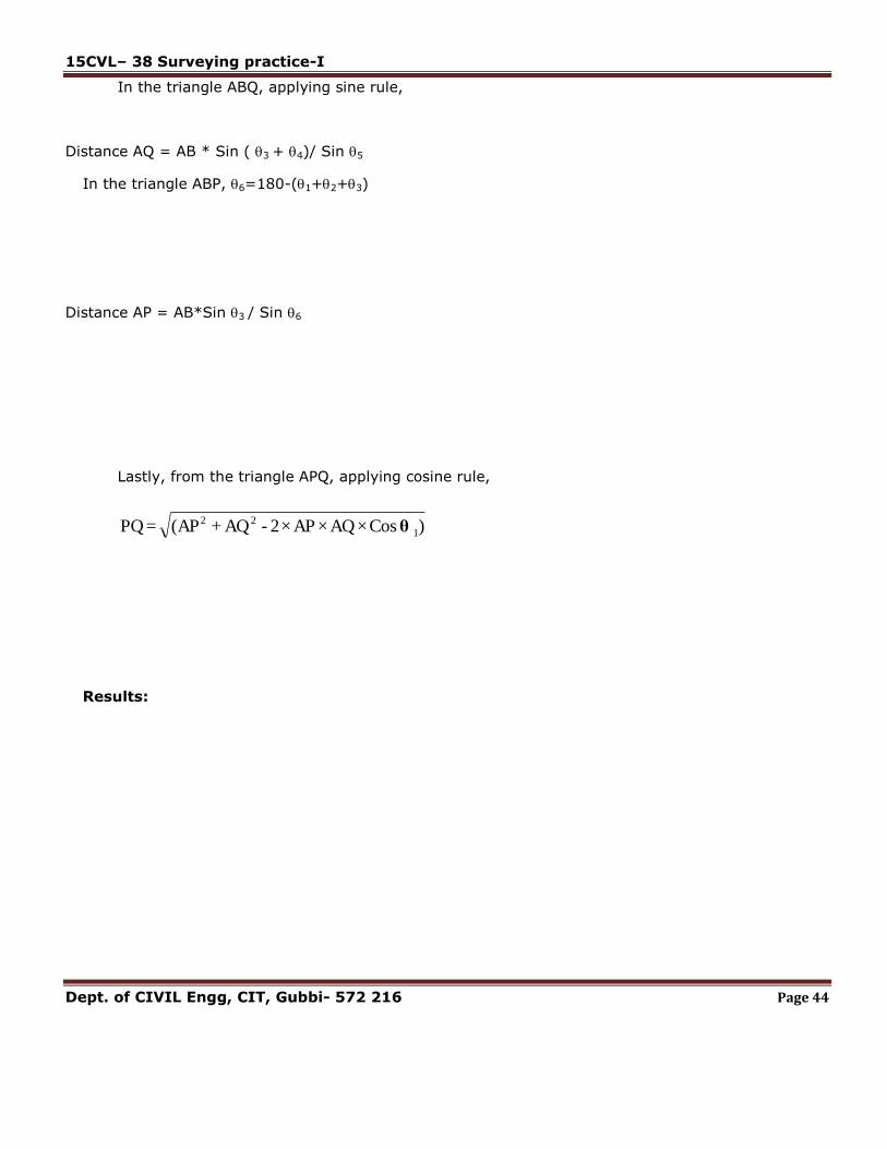
In the triangle ABQ, applying sine rule,
Distance AQ = AB * Sin ( 3 + 4)/ Sin 5
In the triangle ABP, 6=180-(1+2+3)
Distance AP = AB*Sin 3 / Sin 6
Lastly, from the triangle APQ, applying cosine rule,
) Cos × AQ × AP ×2 -AQ + (AP = PQ 1
22θ
Results:

15CVL– 38 Surveying practice-I
Dept. of CIVIL Engg, CIT, Gubbi- 572 216 Page 45
Fig. 6.1Simple Leveling
Observations and tabulations:
Simple leveling
Station B. S. F. S. H.I R. L. Remarks
B.M.
B.S. F.S

15CVL– 38 Surveying practice-I
Dept. of CIVIL Engg, CIT, Gubbi- 572 216 Page 46
Experiment No : 6 Date: __ /__ / __
SIMPLE LEVELING
Aim:To determine the reduced level of points using dumpy level
Instruments used:
Procedure:
1. The instrument is set up at a convenient point A (Fig 6.1), and back sight is taken on the staff
held on the temporary bench mark of assumed RL. The height of the instrument is determined
by adding BS reading to the RL of TBM.
2. The staff is now kept at the destination point and reading is taken. This reading is entered in FS
column.
3. Arithmetic check is made using the following equation.
B.S. - F.S. = Last R.L. – First R.L
Sl.
No. Particulars Quantity
1. Dumpy level 01
2. Tripod 01
3. Levelling Staff 01

15CVL– 38 Surveying practice-I
Dept. of CIVIL Engg, CIT, Gubbi- 572 216 Page 47
Fig. 7.1 Differential leveling.
Station B. S. I. S. F. S. H.I R. L. Remarks
B.M.
B.S. F.S
BS
BM
FS
BS FS
BS FS
A
B
BSFS
P 1
P 2
P 3
P 4

15CVL– 38 Surveying practice-I
Dept. of CIVIL Engg, CIT, Gubbi- 572 216 Page 48
Experiment No : 7 Date: __ /__ / __
DIFFERENTIAL LEVELING
Aim:To determine difference in elevation between two points using differential leveling
Instruments used:
Procedure:
1. The instrument is set up at a convenient point P1(Fig 7.1) and back sight is taken on the staff
held on the temporary bench mark of assumed RL. The height of the instrument is determined
by adding BS reading to the RL of TBM.
2. The staff reading is taken at the starting point and is entered in fore sight column. The R.L. of
the starting point is determined by subtracting staff reading fromheight of the instrument.
R.L. of starting point = Height of the instrument – Fore sight
3. The instrument is shifted to the position P2 and staff reading is taken at starting point and is
entered in back sight column in level with fore sight reading from previous station in the level
book. The new height of the instrument is determined.
4. Above procedure is repeated for rest of the points.
5. Arithmetic check is made using the following equation.
B.S. - F.S. = Last R.L. – First R.L.
Sl.
No. Particulars Quantity
1. Dumpy level 01
2. Tripod 01
3. Levelling Staff 01

15CVL– 38 Surveying practice-I
Dept. of CIVIL Engg, CIT, Gubbi- 572 216 Page 49
Fig. 9.1 Inverted leveling.
Sl No Back Sight
(BS)
Intermediate
Sight (IS)
Fore Sight
(FS)
Height of
the
Instrument
(HI)
Reduced
Level
(RL)
Remarks
15CVL– 38 Surveying practice-I
Dept. of CIVIL Engg, CIT, Gubbi- 572 216 Page 50
Date: __ /__ / __
INVERTED LEVELING
Exersice No: 7.1
Aim: To Determination the RL of an object above the plane of collimation using inverted leveling.
Instruments used:
Theory: When the B.M of staff station is above the line of collimation (or line of sight) the staff is
held inverted on the point and reading is taken .This reading being negative is entered in the level
field book with minus sign, or to avoid confusion, „Staff inverted‟ should be written in the remarks
column against the entry of the reading.
Procedure:
1. Setup the tripod at the convenient plane surface & fix the dumpy level on it.
2. Temporary adjustments are done and the instrument is leveled by using the bubble tube.
3. After leveling the instrument, the leveling staff is held on the given bench mark which is
above the line of sight. Here the staff is held inverted as the object lies above the line of
sight of the instrument.
4. The reading is entered in BS column with a negative sign.
5. Required numbers of intermediate staff readings are taken in the direction of last point.
6. The RL of the given point is calculated by plane of collimation method.
Result:
The RL of the given point with respect to the bench mark which is above the line of sight is
_______________
Sl. No. Particulars Quantity
1. Dumpy level 01
2. Tripod 01
3. Levelling Staff 01

15CVL– 38 Surveying practice-I
Dept. of CIVIL Engg, CIT, Gubbi- 572 216 Page 51
Fig. 8.2 Reciprocal leveling.
Tabulations and Calculations:
Instrument at Staff reading on Remarks
A
B
hal
e
ha
hbl
ebh
PLAN
(B.M)
A
(B.M)
B
A
A
B
B
HORIZONTAL LINE
HORIZONTAL LINE
LEVEL LINE
LEVEL LINE

15CVL– 38 Surveying practice-I
Dept. of CIVIL Engg, CIT, Gubbi- 572 216 Page 52
Experiment No : 8 Date: __ /__ / __
RECIPROCAL LEVELING
Aim: To determine the difference in elevation between two pointsusingreciprocal leveling and
determination of collimation error.
Theory: When it is necessary to carry leveling across a river or any other obstacle requiring a long
sight between two points so situated that no points for the level is found in between them, in that cases
reciprocal leveling may be used (if the width of is small) to obtain accuracy and to eliminate the
following:
1. Error in the instrument adjustment;
2. Combined effect of earth‟s curvature and the refraction of the atmosphere; and
3. Variation in the average refraction.
Let A and B be the points on the opposite banks of a river. The following procedure is used.
Instruments used:
Procedure:
1. Drive pegs at A and B. Set up the instrument near the peg A. Take readings h a and h b on the
staffs held at A and B respectively. The reading h a will have to taken through the objective if
instrument is very near to A.
2. Shift the instrument to near the peg B. Take readings h1
a and h1
b on the staffs held at A and B
respectively. The reading h1
b will have to taken through the objective if instrument is very near to
B.
Sl.
No. Particulars Quantity
1. Dumpy level 01
2. Tripod 01
3. Levelling Staff 01

15CVL– 38 Surveying practice-I
Dept. of CIVIL Engg, CIT, Gubbi- 572 216 Page 53
15CVL– 38 Surveying practice-I
Dept. of CIVIL Engg, CIT, Gubbi- 572 216 Page 54
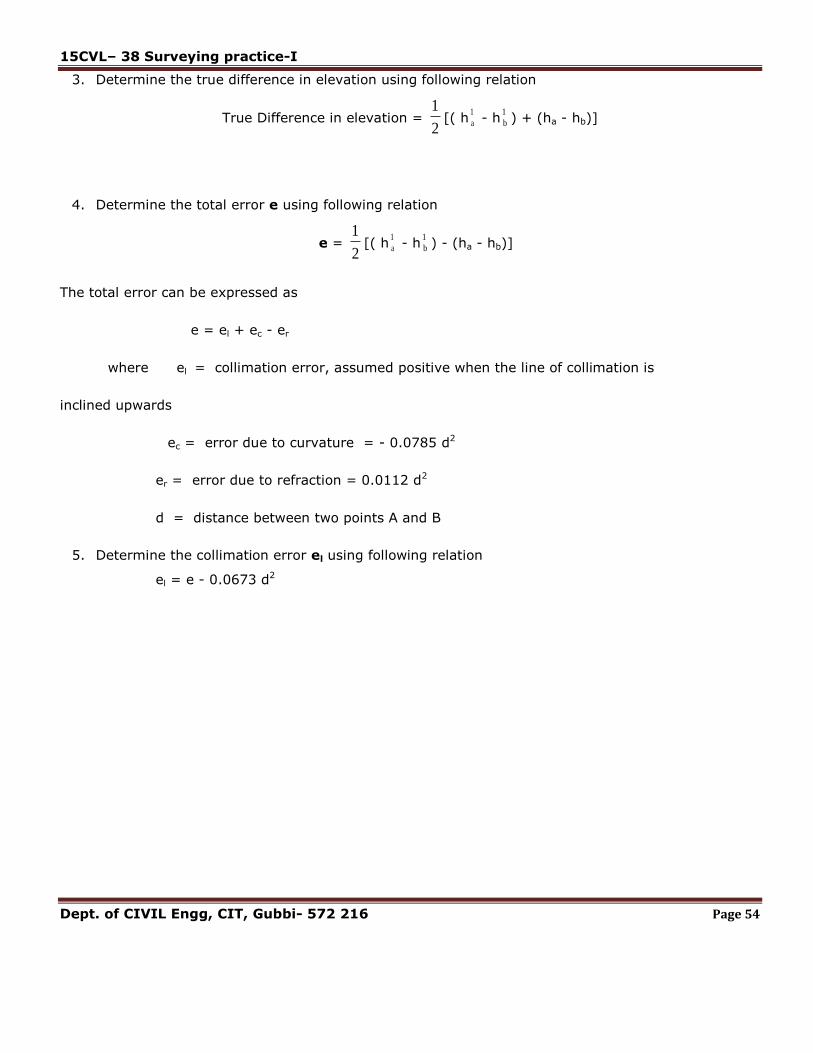
3. Determine the true difference in elevation using following relation
True Difference in elevation = 2
1[( h
1
a - h1
b ) + (ha - hb)]
4. Determine the total error e using following relation
e = 2
1[( h
1
a - h1
b ) - (ha - hb)]
The total error can be expressed as
e = el + ec - er
where el = collimation error, assumed positive when the line of collimation is
inclined upwards
ec = error due to curvature = - 0.0785 d2
er = error due to refraction = 0.0112 d2
d = distance between two points A and B
5. Determine the collimation error el using following relation
el = e - 0.0673 d2
15CVL– 38 Surveying practice-I
Dept. of CIVIL Engg, CIT, Gubbi- 572 216 Page 55
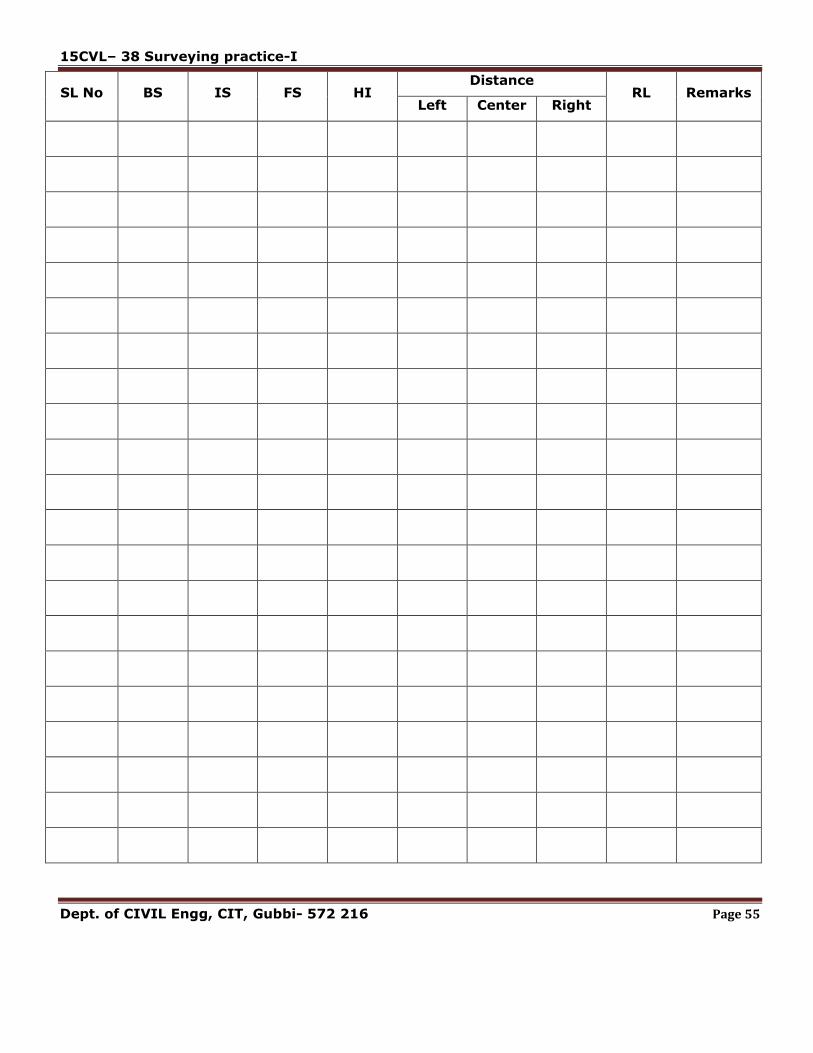
SL No BS IS FS HI Distance
RL Remarks Left Center Right

15CVL– 38 Surveying practice-I
Dept. of CIVIL Engg, CIT, Gubbi- 572 216 Page 56
Experiment No : 9 Date: __ /__ / __
PROFILE AND CROSS SECTION LEVELING
Aim:To conduct profile leveling and cross sectioning,plotting using excel
Theory: It is the operation to determine the elevations of points, which are equally spaced along a
given alignment to know the profile of the ground. The purpose of profile levelling is to determine the
depth of cut or height of embankment for a given gradient selected. It is very useful for projects like
constructions and design of sewers, pipelines, Highways, Railways, Canals, etc.
Instruments used:
Procedure: Following procedure is adopted in Profile leveling along a given alignment.
1. Lay the chain on the ground and stretch it.
2. Locate the points on the chain line at equal distance in the longitudinal direction and
transverse direction using cross staff.
3. Setup the tripod at the convenient plane surface & fix the dumpy level on it.
4. Temporary adjustments are done and the instrument is leveled by using the bubble tube.
Sl.
No. Particulars Quantity
1. Dumpy level 01
2. Tripod 01
3. Levelling Staff 01
4 Chain 01
5 Tape 01
6 Compass 01
7 Arrows few
8 Ranging rods few

15CVL– 38 Surveying practice-I
Dept. of CIVIL Engg, CIT, Gubbi- 572 216 Page 57
Fig. 9.1 Profileleveling.
Fig. 9.2 Cross-sectional leveling.

15CVL– 38 Surveying practice-I
Dept. of CIVIL Engg, CIT, Gubbi- 572 216 Page 58
5. After leveling the instrument, the leveling staff is held on the given bench mark.
6. Take the levels at the marked points on the chain line along the longitudinal and
and transverse direction and enter the readings in respective columns.
7. Shift the level if required. The procedure is repeated until we reach the last point.
8. The longitudinal and cross sections of the ground are plotted using excel.
15CVL– 38 Surveying practice-I
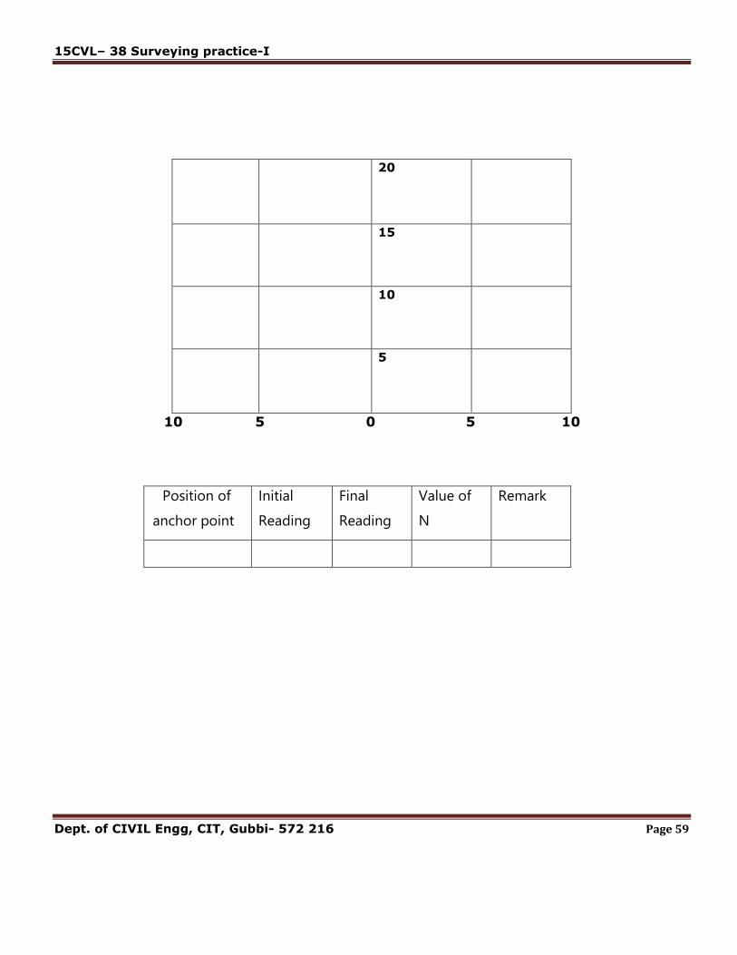
Dept. of CIVIL Engg, CIT, Gubbi- 572 216 Page 59
Position of
anchor point
Initial
Reading
Final
Reading
Value of
N
Remark
20
15
10
5
10 5 0 5 10

15CVL– 38 Surveying practice-I
Dept. of CIVIL Engg, CIT, Gubbi- 572 216 Page 60
Date: __ /__ / __
BLOCKLEVELING
Exersice No: 9.1
Aim: To conduct block leveling, preparation of contour plan using excels. Use of planimeter/graph
and computations of Areas and volumes.
Instruments used:
Theory: CONTOURING: The elevation and depression the undulations of the surface of the ground
are shown as map by interaction of level surface with by means of contour line. a contour may be
defined as the line of intersection of a level surface with the surface of the ground.
Procedure:
1. Lay the chain on the ground and stretch it.
2. Locate the points on the chain line at equal distance in the longitudinal direction and transfers
direction.
3. Setup the tripod at the convenient plane surface & fix the dumpy level on it.
4. Temporary adjustments are done and the instrument is leveled by using the bobble tube.
5. After leveling the instrument, the leveling staff held on the given bench mark.
6. Divide the total area into number of blocks having equal area.
7. The corners of the blocks are marked with arrows.
8. The elevations of the ground at the corners of squares are taken and enter in to tabular columns
Sl.
No. Particulars Quantity
1. Dumpy level 01
2. Tripod 01
3. Levelling Staff 01
4 Chain 01
5 Tape 01
6 Compass 01
7 Arrows few
8 Ranging rods few

15CVL– 38 Surveying practice-I
Dept. of CIVIL Engg, CIT, Gubbi- 572 216 Page 61
SL No BS IS FS HI Distance
RL Remarks Left Center Right

15CVL– 38 Surveying practice-I
Dept. of CIVIL Engg, CIT, Gubbi- 572 216 Page 62
9. The systems of squares are potted on the drawing sheet. The respective RL shell be entered
near each respective corners.
10. The contour of required RL‟s are plotted.
LOCATING CONTOURS:
This method is commonly used in rough survey, cross sections are run traverse to the contour line of
road, and railway as canal and the point of change of slope (representations) are located. The cross-
section line may be inclined at any angle To the centerline if necessary. The spacing of the cross
sections depends upon the characteristics of the ground.
By interpolation of contour is meant the process of spacing the contour proportioning between the
plotted ground points. Contour may be interpolated by
1) Estimation
2) Arithmetical calculations
3) Graphical method .in all these methods
It is assumed that the slope of the ground between any two random points is uniform.
RESULT:The contour of given land is drawn in excel sheet.

15CVL– 38 Surveying practice-I
Dept. of CIVIL Engg, CIT, Gubbi- 572 216 Page 63
INTRODUCTION ON THEODOLITE
Theodolite is a survey instrument widely used in survey for its capability of being employed in the
very accurate determination of horizontal and vertical angles.
There are two types of theodolite, namely:
1) Transit theodolite.
2) Non-transit theodolite.
Transit theodolite:A transit theodolite is one in which the line of sight is reversed by revelling the
telescope through 180 o in the vertical plane. This complete revolution is known as transit theodolite.
Transit theodolite
Non-Transit theodolite:
A non-transit theodolite is either plain theodolite or Y- theodolite in which the telescope can not be
rotated in a vertical plane through complete revolution.The transit is mainly used & non-transit
theodolite is now become absolute.

15CVL– 38 Surveying practice-I
Dept. of CIVIL Engg, CIT, Gubbi- 572 216 Page 64
The transit theodolite contents the following parts,
1. Telescope
2. Clamp screw
3. Focussing screw
4. Horizontal axis
5. tangent screw
6. standard
7. upper plate
8. Lower plate
9. inner axis
10. outer axis
11. Tribranch
12. foot screw
13. trivet
14. tripod stand
15. wing nut
16. plumb bob
17. plate bubble
18. index bar
19. tabular compass
20. altitude bubble
21. adjustable mirror
22. vertical circle
Trivet: Itis a circular plate having a central threaded hole for fixing the theodolite on the tripod stand
by a wingnut.it is also called the base plate. Three foot screws are secured to this plate by means of
a ball and socket arrangement.
Foot screws: These are meant for levelling the instrument the lower part of the foot screws are
secured in the trivet by means of a ball and socket arrangements and the upper threaded part passes
through the threaded hole in the tribranch plate.
Levelling head: The trivet, foot screws and the tribranch constitute a body which is known as the
levelling head.
Spindles: The theodolite consists of two spindles or axes one inner and the other outer, inner axis is
solid and conical and the outer is hallow. Two spindles are co-axial.
Lower plate:The lower plate is attached to the outer axis and is also known as the scale plate. It is
bevelled and the scale is graduated from 0o to 360o in a clockwise direction each degree is again
subdivided in to two, three or four divisions. Thus the value of one small division may be 30,20&15
respectively.
The lower plate is provided with a clamp screw and a tangent screw which control its movements
when the clamp screw is tightened. This plate is fixed with the outer axis for fine adjustment of the

15CVL– 38 Surveying practice-I
Dept. of CIVIL Engg, CIT, Gubbi- 572 216 Page 65
lower plate. The tangent screw is rotated to the extent required the size of the theodolite is
designated according to the diameter of the lower plate.
Upper plate:The upper plate contains the vernier scales A & B. it is attached to the inner axis. Its
motion is controlled by the upper clamp screw and upper tangent screw. When the clamp screw is
tightened the vernier scales are fixed with the inner axis and for fine adjustment of the scale the
tangent screw is rotated.
Plate bubble :Two plate bubbles are mounted at right angle to each other on the upper surface of
the vernier plate. one bubble is kept parallel to the horizontal axis of the theodolite sometimes one
plate bubble is provided on the vernier plate. The bubble is provided on the vernier plate the bubbles
are meant for levelling the instrument at the times of measuring the horizontal angles.
Standard or A-frame:Two frames (shaped like the letter A) are provided on the upper plate to
support the telescope, the vertical circle and the vernier scales. These frames are known as
standards or A frames.
Telescope:The telescope is provided between the standards at right angles to the horizontal axis it
can be rotated about its horizontal axis in a vertical plane. The telescope is provided with a focussing
screw clamping screw and tangent screw.
Vertical circle:The vertical circle is rigidly fixed with the telescope and moves with it. It is divided in
to four quadrant, each quadrant is graduated from 0 90 in opposite direction with the zero mark at
the ends of the horizontal diameter through vertical circle.
The line joining the zero marks corresponding to the collimation. The sub divisions of the vertical
circle are similar to these of the horizontal circle. The vertical circle can be clamped or finely adjusted
with the help of the clamping screw and the tangent screw provided along with the telescope
Index bar or T-frame:The index bar is provided on the standard in front of the vertical circle. It
carries two verniers(C&D) at the two ends of the horizontal arm the vertical leg of the index bar is
provided with a clip screw at the lower end by means of which the altitude bubble can be brought to
the centre.
Altitude bubble:A long sensitive bubble tube is provided on the top of index bar, the bubble it
contains is known as the altitude bubble. This bubble is brought to the centre by the clip screw at the

15CVL– 38 Surveying practice-I
Dept. of CIVIL Engg, CIT, Gubbi- 572 216 Page 66
time of measuring the vertical angle. A mirror is provided on the top of the bubble to help observe it
when the instrument is set up above normal height.
Compass:Some times a circular box compass is mounted on the verneir scale between the standard
in modern theodolites, an adjustable through compass or tabular compass can be fitted with a screw
to the standard. The compass is provided for taking the magnetic bearing of a line.

15CVL– 38 Surveying practice-I
Dept. of CIVIL Engg, CIT, Gubbi- 572 216 Page 67
Fig: 10.1 Method of repetition
In
str
um
en
t sta
tio
n
Sig
hte
d T
o
Face Left Swing Right Face Right Swing Right
Average
Horizont
al Angle A B Mean
No
Of
Rep
itit
ion
s
Horizon
tal
Angle
A B Mean
No
Of
Rep
itit
ion
s
Horizo
ntal
Angle
° ‘ “ ‘ “ ° ‘ “ ° ‘ “ ° ‘ “ ‘ “ ° ‘ “ ° ‘ “ ° ‘ “
A
B
A
B
15CVL– 38 Surveying practice-I
Dept. of CIVIL Engg, CIT, Gubbi- 572 216 Page 68
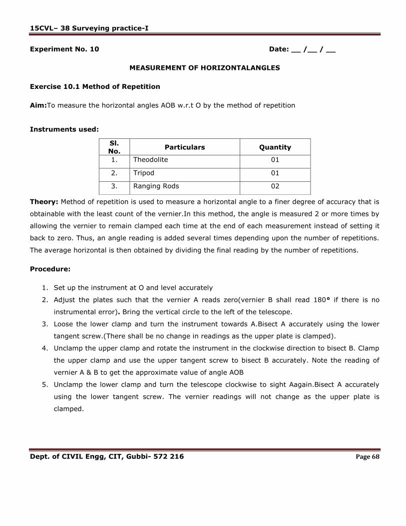
Experiment No. 10 Date: __ /__ / __
MEASUREMENT OF HORIZONTALANGLES
Exercise 10.1 Method of Repetition
Aim:To measure the horizontal angles AOB w.r.t O by the method of repetition
Instruments used:
Theory: Method of repetition is used to measure a horizontal angle to a finer degree of accuracy that is
obtainable with the least count of the vernier.In this method, the angle is measured 2 or more times by
allowing the vernier to remain clamped each time at the end of each measurement instead of setting it
back to zero. Thus, an angle reading is added several times depending upon the number of repetitions.
The average horizontal is then obtained by dividing the final reading by the number of repetitions.
Procedure:
1. Set up the instrument at O and level accurately
2. Adjust the plates such that the vernier A reads zero(vernier B shall read 180° if there is no
instrumental error). Bring the vertical circle to the left of the telescope.
3. Loose the lower clamp and turn the instrument towards A.Bisect A accurately using the lower
tangent screw.(There shall be no change in readings as the upper plate is clamped).
4. Unclamp the upper clamp and rotate the instrument in the clockwise direction to bisect B. Clamp
the upper clamp and use the upper tangent screw to bisect B accurately. Note the reading of
vernier A & B to get the approximate value of angle AOB
5. Unclamp the lower clamp and turn the telescope clockwise to sight Aagain.Bisect A accurately
using the lower tangent screw. The vernier readings will not change as the upper plate is
clamped.
Sl.
No. Particulars Quantity
1. Theodolite 01
2. Tripod 01
3. Ranging Rods 02

15CVL– 38 Surveying practice-I
Dept. of CIVIL Engg, CIT, Gubbi- 572 216 Page 69

15CVL– 38 Surveying practice-I
Dept. of CIVIL Engg, CIT, Gubbi- 572 216 Page 70
6. Unclamp the upper clamp and rotate the instrument in the clockwise direction to bisect B. Clamp
the upper clamp and use the upper tangent screw to bisect B accurately.
7. Repeat the process till the angle is repeated the required number of times.
8. Change the face by transiting the telescope and repeat the whole process for the other face
readings
9. The average horizontal angle is then obtained by taking the mean of the two readings with
different faces
RESULTS:- The average horizontal angle = _________

15CVL– 38 Surveying practice-I
Dept. of CIVIL Engg, CIT, Gubbi- 572 216 Page 71
Fig 10.2 Method of Reiteration
In
str
um
en
t sta
tio
n
Sig
hte
d T
o
Face Left Swing Right Face Right Swing Right Averag
e
Horizon
tal
Angle
A B Mean
No
Of
Rep
itit
ion
s
Horizon
tal
Angle
A B Mean
No
Of
Rep
itit
ion
s
Horizo
ntal
Angle
° ‘ “ ‘ “ ° ‘ “ ° ‘ “ ° ‘ “ ‘ “ ° ‘ “ ° ‘ “ ° ‘ “

15CVL– 38 Surveying practice-I
Dept. of CIVIL Engg, CIT, Gubbi- 572 216 Page 72
Exercise No. 10.2 Date: __ /__ / __
Aim:To measure the horizontal angles AOB, BOC, COD etc by the method of reiteration
Instruments used:
Theory: This method is suitable for measurements of the angles of a group having a common vertex
point. Several angles are measured successively and finally the horizon is closed (closing the horizon is
the process of measuring the angles around a point to obtain a check on their sum, which should be
360°
Procedure:
1. Set up the instrument at O and level accurately
2. Adjust the plates such that the vernier A reads zero(vernier B shall read 180° if there is no
instrumental error). Bring the vertical circle to the left of the telescope.
3. Loose the lower clamp and turn the instrument towards A (or any other reference point).Bisect A
accurately using the lower tangent screw.
4. Unclamp the upper clamp and rotate the instrument in the clockwise direction to bisect B. Clamp
the upper clamp and use the upper tangent screw to bisect B accurately. Note the reading of
vernier A & B the mean of the vernier readings will give angle AOB
5. Similarly bisect C and D successively, thus closing the circle. Each included angle is obtained by
taking the difference between two consecutive readings
6. On the final sight to A, the reading of the vernier should be either 0° or 360°.If not note the
vernier readings and find the error due to slip, and if the error is small distribute it equally to all
the angles. If large repeat the procedure and take fresh readings.
7. Repeat the step with the other faces
Results: The average horizontal angle
AOB =_______BOC= ________COD=________DOA=________
Sl.
No. Particulars Specification Quantity
1. Theodolite 01
2. Tripod 01
3. Ranging Rods 04

15CVL– 38 Surveying practice-I
Dept. of CIVIL Engg, CIT, Gubbi- 572 216 Page 73
Fig 13.1 Single plane method (Base accessible)
In
str
um
en
t A
t
Sig
hte
d T
o
Face : Left Face : Right Averag
e
vertical
Angle
C D Mean Vertical
Angle
C D Mean
Vertical
Angle
° ‘ “ ‘ “ ° ‘ “ ° ‘ “ ° ‘ “ ‘ “ ° ‘ “ ° ‘ “ ° ‘ “
A P‟
Date: __ /__ / __

15CVL– 38 Surveying practice-I
Dept. of CIVIL Engg, CIT, Gubbi- 572 216 Page 74
VERTICAL ANGLE
Exercise No. 10.3 SINGLE PLANE METHOD
Aim: To determine the elevation of an object using single plane method when base is accessible
Instruments used:
Theory: The method is said to be a single plane method when the instrument station are in the same
vertical plane as that of the elevated object
Procedure:
1. Identify the object whose elevation is to be determined
2. Identify the BM and record the RL of BM
3. Set up the instrument at station A and perform the temporary adjustments
4. Take the staff reading on BM keeping the telescope horizontal (vernier C and D reading zero)
5. Focus the telescope to the top of the object (P‟) and measure the angle of elevation ө (take face
left and face right observations)
6. Measure the distance D accurately
Sl.
No. Particulars Quantity
1. Theodolite 01
2. Tripod 01
3. Ranging Rods few
4. Tape 01
5 Leveling staff 01

15CVL– 38 Surveying practice-I
Dept. of CIVIL Engg, CIT, Gubbi- 572 216 Page 75
Calculations:

15CVL– 38 Surveying practice-I
Dept. of CIVIL Engg, CIT, Gubbi- 572 216 Page 76
Let
A = Instrument station
A‟ =Centre of the instrument
P‟ = Point to be observed
P” = Projection of P‟
h = P”P‟
s = Reading of staff kept on BM with
line of sight horizontal
ө = Angle of elevation from A‟ to P‟
h‟=PP”
consider triangle A‟P‟P”
tanө= h/D
Therefore h= D tanө
RL of P‟ = RL of BM + s + D tanө
The height of the object = h‟+ h
1. Staff reading s = ______m
2. Angle of elevation ө = _________ (average of both the face values)
Results: Level of top of the object when the base is accessible = _______m

15CVL– 38 Surveying practice-I
Dept. of CIVIL Engg, CIT, Gubbi- 572 216 Page 77
Fig 10.4 single plane method (base Inaccessible)
In
str
um
en
t A
t
Sig
hte
d T
o
Face : Left Face : Right Averag
e
vertical
Angle
C D Mean Vertical
Angle
C D Mean
Vertical
Angle
° ‘ “ ‘ “ ° ‘ “ ° ‘ “ ° ‘ “ ‘ “ ° ‘ “ ° ‘ “ ° ‘ “
A P‟
B P‟
Exercise No. 10.4 Date: __ /__ / __

15CVL– 38 Surveying practice-I
Dept. of CIVIL Engg, CIT, Gubbi- 572 216 Page 78
Aim: To determine the elevation of an object using single plane method when base is inaccessible
Instruments used:
Case 1 : when the instrument station near the object is at lower elevation than the other
Let h1 = P”P‟
h2 = P”‟P‟
s1 = Reading of staff kept on BM from instrument station A
s2 = Reading of staff kept on BM from instrument station B
ө1 = Angle of elevation from A‟ to P‟
ө2 = Angle of elevation from B‟ to P‟
d= Horizontal distance between two instrument stations
D = Horizontal distance between A and P
Considering triangle A‟P‟P”
tanө1=h1/D
h1 = D tanө1 (1)
Considering triangle B‟P‟P”
tanө2=h2/(d+D)
Sl.
No. Particulars Quantity
1. Theodolite 01
2. Tripod 01
3. Ranging Rods few
4. Tape 01
5 Leveling staff 01

15CVL– 38 Surveying practice-I
Dept. of CIVIL Engg, CIT, Gubbi- 572 216 Page 79
h2 = (d+D) tanө2 (2)

15CVL– 38 Surveying practice-I
Dept. of CIVIL Engg, CIT, Gubbi- 572 216 Page 80
From (1) & (2)
D = (dtanө2+s)/(tanө1-tanө2) (3)
RL of P‟ from A = RL of BM + s1+ h1
Check:RL of P‟ from B = RL of BM + s2+ h2
s is +ve when station A is lower than B
s is –ve when station A is higher than B
Procedure:
1. Identify the object whose elevation is to be determined
2. Set up the instrument at station A and perform the temporary adjustments. Take the
staff reading on BM keeping the telescope horizontal as s1 (vernier C and D reading zero)
3. Focus the telescope to the top of the object (P‟) and measure the angle of elevation ө1
(take face left and face right observations)
4. Transit the theodolite to reverse the line of sight and fix a point B at a measured distance
d.
5. Shift the instrument to B and perform the temporary adjustments. Take the staff reading
on BM keeping the telescope horizontal as s2 (vernier C and D reading zero)
6. Focus the telescope to the top of the object (P‟) and measure the angle of elevation ө2
(take face left and face right observations)
Results:
RL of P’ = _________m

15CVL– 38 Surveying practice-I
Dept. of CIVIL Engg, CIT, Gubbi- 572 216 Page 81
Fig:10.5 Double Plane Method
In
str
um
en
t A
t
Sig
hte
d T
o
Face : Left Swing : Right Face : Right Swing : Right Average
Horizont
al
Angle
A B Mean
Horizonta
l
Angle
A B Mean
Horizont
al
Angle
° ‘ “ ‘ “ ° ‘ “ ° ‘ “ ° ‘ “ ‘ “ ° ‘ “ ° ‘ “ ° ‘ “

15CVL– 38 Surveying practice-I
Dept. of CIVIL Engg, CIT, Gubbi- 572 216 Page 82

15CVL– 38 Surveying practice-I
Dept. of CIVIL Engg, CIT, Gubbi- 572 216 Page 83
In
str
um
en
t A
t
Sig
hte
d T
o
Face : Left Face : Right Averag
e
vertical
Angle
C D Mean Vertical
Angle
C D Mean
Vertical
Angle
° ‘ “ ‘ “ ° ‘ “ ° ‘ “ ° ‘ “ ‘ “ ° ‘ “ ° ‘ “ ° ‘ “
A P‟
B P‟

15CVL– 38 Surveying practice-I
Dept. of CIVIL Engg, CIT, Gubbi- 572 216 Page 84
Date: __ /__ / _
DOUBLE PLANE METHOD
Exercise No. 10.5
Aim: To determine the distance and difference in elevation between two inaccessible points using
double plane method.
Instruments used:
Theory: Method is said to be double plane when the instrument stations are not in same vertical plane
as that of elevated objects
Let A & B = Instrument stations
P = Base of the object
ө1 = Angle of elevation from A‟ to P‟
ө2= Angle of elevation from B‟ to P‟
s1 = Reading of staff kept on BM from instrument station A
s2 = Reading of staff kept on BM from instrument station B
Considering triangle ABP
We have
α & β = Known(measured)
Sl.
No. Particulars Specification Quantity
1. Theodolite 01
2. Tripod 01
3. Ranging Rods few
4. Tape 01
5 Levelling staff 01

15CVL– 38 Surveying practice-I
Dept. of CIVIL Engg, CIT, Gubbi- 572 216 Page 85

15CVL– 38 Surveying practice-I
Dept. of CIVIL Engg, CIT, Gubbi- 572 216 Page 86
Therefore ø =(180- α - β )
Applying sine rule
AP/sin α =BP/sin β = AB/sin ø
But AB=d
Therefore
AP = d sin α/sin ø, BP = d sin β/sin ø
To determine the elevation of P‟
RL of P‟ = RL of BM + s1 + AP tan ө1
RL of P‟ = RL of BM + s2 + BP tanө2
Procedure:
1. Set up the theodolite at A and measure distance d accurately to mark B
2. Measure angle BAP (β)
3. Sight p‟ and measure the vertical angle ө1
4. With the telescope horizontal take the staff reading s1 on the BM
5. Shift the instrument to station B and measure the horizontal angle PBA (α)
6. Sight P‟ and measure the vertical angle ө2
7. With the telescope horizontal take staff reading s2 on the BM
Results: RL of to of the object = _______m

15CVL– 38 Surveying practice-I
Dept. of CIVIL Engg, CIT, Gubbi- 572 216 Page 87
Fig: 12.1
Distance
Staff Reading
Staff Intercept Multipying
Constant K
Additive
Contant C Upper Hair (m) Lower Hair (m)
15CVL– 38 Surveying practice-I
Dept. of CIVIL Engg, CIT, Gubbi- 572 216 Page 88
Experiment No. 12 Date: __ /__ / __
TACHEOMETRY
Exercise No. 12.1
Aim: To determine the tacheometric constants using horizontal line of sight.
Instruments used:
Procedure:
1. Measure a total distance of 80m on the ground and put pegs at 20m interval (on a fairly level
ground)
2. Set the tacheometer at the zero chain age and do the temporary adjustments
3. Take the stadia readings keeping the levelling staff at 20m, 40m, 60m and 80m keeping the
telescope horizontal thought
Calculations:
D1=Ks1+C
D2=Ks2+C … so on
Solving any 2 equations we get set of K & C values.
Results:Average value of the tacheometric constants
K=______
C=_______
Sl.
No. Particulars Specification Quantity
1. Theodolite 01
2. Tape 01
3. Ranging Rods 03
4. Arrows few
5. Leveling staff 01
6. Chain 01

15CVL– 38 Surveying practice-I
Dept. of CIVIL Engg, CIT, Gubbi- 572 216 Page 89
Fig4.2
Distance
Staff Reading
Staff Intercept Multipying
Constant K
Additive
Contant C Upper Hair (m) Lower Hair (m)

15CVL– 38 Surveying practice-I
Dept. of CIVIL Engg, CIT, Gubbi- 572 216 Page 90
Exercise No. 12.2 Date: __ /__ / __
Aim: To determine the tacheometric constants using inclined line of sight.
Instruments used:
Procedure:
1. Measure a total distance of 80m on the ground and put pegs at 20m interval (on a fairly level
ground)
2. Set the tacheometer at the zero chainage and do the temporary adjustments
3. Fix the telescope to some angle and take the stadia readings keeping the levelling staff at 20m,
40m, 60m and 80m.
Calculations:
D1=Ks1cos²ø+cosø
D2=Ks2cos²ø+cosø … so on
Solving any 2 equations we get set of K & C values.
Sl.
No. Particulars Specification Quantity
1. Theodolite 01
2. Tape 01
3. Ranging Rods 03
4. Arrows few
5. Leveling staff 01
6. Chain 01