Embed Size (px)
Citation preview
A parametric, experimental analysis of conical vortices on curved roofs of low-rise buildings
S. Franchini*, S. Pindado, J. Meseguer, A. Sanz-Andres
Abstract
Different methods to reduce the high suction caused by conical vortices have been reported in the literature: vertical parapets, either solid or porous, placed at the roof edges being the most analysed configuration. Another method for alleviating the high suction peaks due to conical vortices is the use of some non-standard parapet configuration like cantilever parapets. In this paper the influence of roof curvature on the conical vortex pattern appearing on a curved roof (Fig. 1) when subject to oblique winds is experimentally analysed by testing the mean pressure distribution on the curved roofs of low-rise building models in a wind tunnel. Also, the efficiency of cantilever parapets to reduce mean suction loads on curved roofs is experimentally checked. Very high suction loads have been measured on curved roofs, the magnitude of these high suction loads being significantly decreased when cantilever parapets are used. Thus, the suitability of these parapets to reduce wind pressure loads on curved roofs is demonstrated.
1. Introduction
The high suction generated in the separated flow regions around bluff bodied structures has caught the interest of wind engineers during the last few decades. These high suction loads are connected to the severe adverse pressure gradients that appear downstream of the roof edges of buildings. Adverse pressure gradients cause the boundary layer around the bodies to separate, and generate a vortex flow pattern characterised by the existence of severe mean suction peaks, which can produce cladding failures. This phenomenon becomes remarkable in the roofs of low-rise buildings with incident wind at oblique angles to the edges, where the existence of such vortex patterns in the region of the windward facing corner is well established at both model scale and full scale.
The structure of these vortices is the subject of considerable research, although efforts related to wind engineering have been mainly focused on flat roof buildings. Concerning flat roofs, in addition to some analytical and numerical approximations [1], the study of the accurate nature of conical vortices has been mainly performed through experimental work made on wind-tunnel models [2-10] and through measurements made on full-scale buildings [11-13]. In the case of flat roofs, the use of parapets, either solid [14-17] or porous [18], to reduce the high suction caused by conical vortices has been studied. Some attempts have been made to analyse conical-vortex effects on curved roofs, either with parapets [19] or without these devices [20], although in this case results are scarce and limited to some particular roof geometries.
From the aerodynamic standpoint, there are some remarkable differences between flat roofs and curved ones. As it is well known, in the case of flat roofs of low-rise buildings, conical vortices form at the windward corner. The highest suction forces appear close to this windward corner and they are obtained for oblique wind directions (on flat roofs of square or nearly square shape, maximum suction is obtained for wind directions close to \i — 45° [17,18], see Fig. 1 for the definition of the wind angle of incidence). However, severe mean-suction peaks usually only affect a small roof area near the windward corner, because the absolute value of the pressure coefficient seems to decrease as the inverse of the square root of the distance to the windward roof corner [5,7].
In the case of curved roofs, fluid behaviour is driven by the fact that at least one of the two edges reaching the windward roof corner is curved. The scope of the analysis is limited to roof geometries like the one represented in Fig. 1, where two of the roof edges are straight lines. The vortex formed at the straight edge behaves like the flat roof case, but at the curved edge the vortex behaviour is affected by the roof curvature. For large wind angles (near 90° as is denned in Fig. 1) curved roofs behave like flat ones (note that the curved edge vortex produces more severe suction loads than the corresponding flat roof vortex, because the area affected by high suction loads is larger in the case of curved roofs). On the other hand, for small wind angles (near 0° as is denned in Fig. 1), if the roof curvature is large enough, the conical vortex is not formed at the windward roof corner but close to the top of the curved edge. Therefore, the pressure distribution close to the curved edge has a minimum at
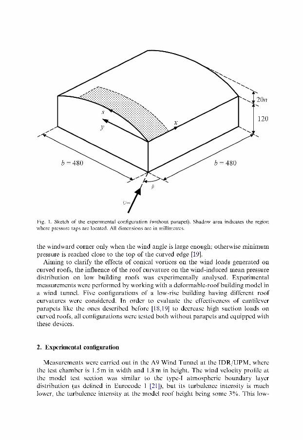
Fig. 1. Sketch of the experimental configuration (without parapet). Shadow area indicates the region where pressure taps are located. All dimensions are in millimetres.
the windward corner only when the wind angle is large enough; otherwise minimum pressure is reached close to the top of the curved edge [19].
Aiming to clarify the effects of conical vortices on the wind loads generated on curved roofs, the influence of the roof curvature on the wind-induced mean pressure distribution on low building roofs was experimentally analysed. Experimental measurements were performed by working with a deformable-roof building model in a wind tunnel. Five configurations of a low-rise building having different roof curvatures were considered. In order to evaluate the effectiveness of cantilever parapets like the ones described before [18,19] to decrease high suction loads on curved roofs, all configurations were tested both without parapets and equipped with these devices.
2. Experimental configuration
Measurements were carried out in the A9 Wind Tunnel at the IDR/UPM, where the test chamber is 1.5 m in width and 1.8 m in height. The wind velocity profile at the model test section was similar to the type-I atmospheric boundary layer distribution (as defined in Eurocode 1 [21]), but its turbulence intensity is much lower, the turbulence intensity at the model roof height being some 3%. This low-
turbulence testing condition has already been used in wind-tunnel tests, and from the standpoint of measuring averaged wind loads, it seems to be a more severe condition than turbulent flow [22-24]. It must be stressed that the aim of the described experiments was to analyse the effect of the roof curvature on the wind loads and not the effect of the incident wind properties.
The wind velocity of the stream at the test section of the wind tunnel, above the boundary layer, was close to 25ms - 1 , which provides a Reynolds number higher than 2 x 10⁵, based on the height of the model with flat roof.
The model, which represents a low-rise building, is a box whose ground plan is a square with sides b = 480 mm length (Fig. 1). Two of the faces of the model are rectangular, 120 mm high, whereas the other two faces, which are removable, have curved upper sides. These curved sides are circular arcs, which are identified by the value of the parameter n, the maximum height of the face being 20(6 + n) mm. Five different sets of curved faces were used (n = 0, 1,2, 3, 4). The roof model consists of a stainless steel foil 0.5 mm thick, with pressure taps. The roof is also removable and it is 480 mm width and 560 mm depth. When mounted on the model, windward edges of the roof are carefully aligned with the external edges of windward faces, so that no eaves exist at the windward sides of the model.
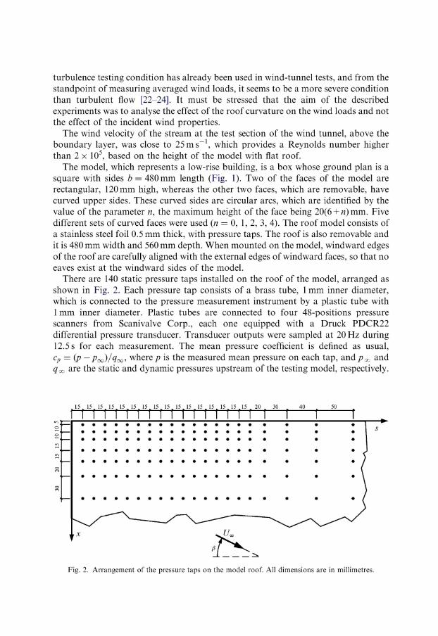
There are 140 static pressure taps installed on the roof of the model, arranged as shown in Fig. 2. Each pressure tap consists of a brass tube, 1 mm inner diameter, which is connected to the pressure measurement instrument by a plastic tube with 1 mm inner diameter. Plastic tubes are connected to four 48-positions pressure scanners from Scanivalve Corp., each one equipped with a Druck PDCR22 differential pressure transducer. Transducer outputs were sampled at 20 Hz during 12.5s for each measurement. The mean pressure coefficient is defined as usual, cp = (p —Po^/qoo, where p is the measured mean pressure on each tap, and^oo and #oo are the static and dynamic pressures upstream of the testing model, respectively.
15 15 15 15 15 15 15 15 15 15 15 . 15 15 . 15 15 15 . 20 _ 30 ^ 40 t 50
Fig. 2. Arrangement of the pressure taps on the model roof. All dimensions are in millimetres.
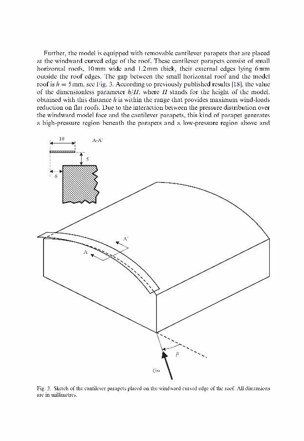
Further, the model is equipped with removable cantilever parapets that are placed at the windward curved edge of the roof. These cantilever parapets consist of small horizontal roofs, 10mm wide and 1.2mm thick, their external edges lying 6mm outside the roof edges. The gap between the small horizontal roof and the model roof is h — 5mm, see Fig. 3. According to previously published results [18], the value of the dimensionless parameter hjH, where H stands for the height of the model, obtained with this distance h is within the range that provides maximum wind-loads reduction on flat roofs. Due to the interaction between the pressure distribution over the windward model face and the cantilever parapets, this kind of parapet generates a high-pressure region beneath the parapets and a low-pressure region above and
Fig. 3. Sketch of the cantilever parapets placed on the windward curved edge of the roof. All dimensions are in millimetres.
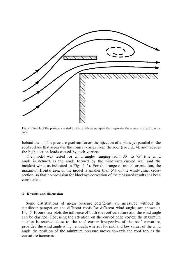
Fig. 4. Sketch of the plain jet created by the cantilever parapets that separates the conical vortex from the roof.
behind them. This pressure gradient forces the injection of a plane jet parallel to the roof surface that separates the conical vortex from the roof (see Fig. 4), and reduces the high suction loads caused by such vortices.
The model was tested for wind angles ranging from 30° to 75° (the wind angle is defined as the angle formed by the windward curved wall and the incident wind, as indicated in Figs. 1-3). For this range of model orientation, the maximum frontal area of the model is smaller than 5% of the wind-tunnel cross-section, so that no provision for blockage correction of the measured results has been considered.
3. Results and discussion
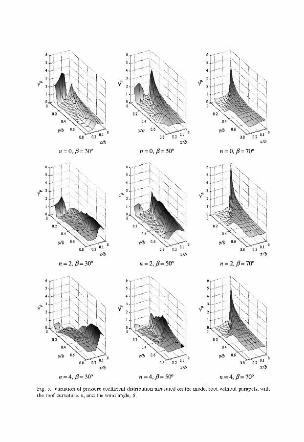
Some distributions of mean pressure coefficient, cp, measured without the cantilever parapet on the different roofs for different wind angles are shown in Fig. 5. From these plots the influence of both the roof curvature and the wind angle can be clarified. Focussing the attention on the curved edge vortex, the maximum suction is reached close to the roof corner irrespective of the roof curvature, provided the wind angle is high enough, whereas for mid and low values of the wind angle the position of the minimum pressure moves towards the roof top as the curvature increases.
0.8 0.2
xfb 0.8 0.2
rJb 18 0.2
(15=0,^=30° n = 0,^=50° n = 0, /?= 70°
x/A
n = 2,J3= 30° n = 2,^=50° n = 2,/3= 70°
x/6
n a 4, /?= 30" n = 4, 0= 50° n = 4,/?=70°
Fig. 5. Variation of pressure coefficient distribution measured on the model roof without parapets, with the roof curvature, n, and the wind angle, /J.
On the other hand, for small values of the wind angle, suction peaks at the windward corner decrease as the roof curvature grows; in such a way that pressure coefficients close to the corner become even positive for large roof curvature (flow is considerably decelerated in this region). However, there is still a conical vortex at the curved edge, although it is now formed close to the top of the roof (the distance from the vortex origin to the windward corner increasing as the roof curvature grows).
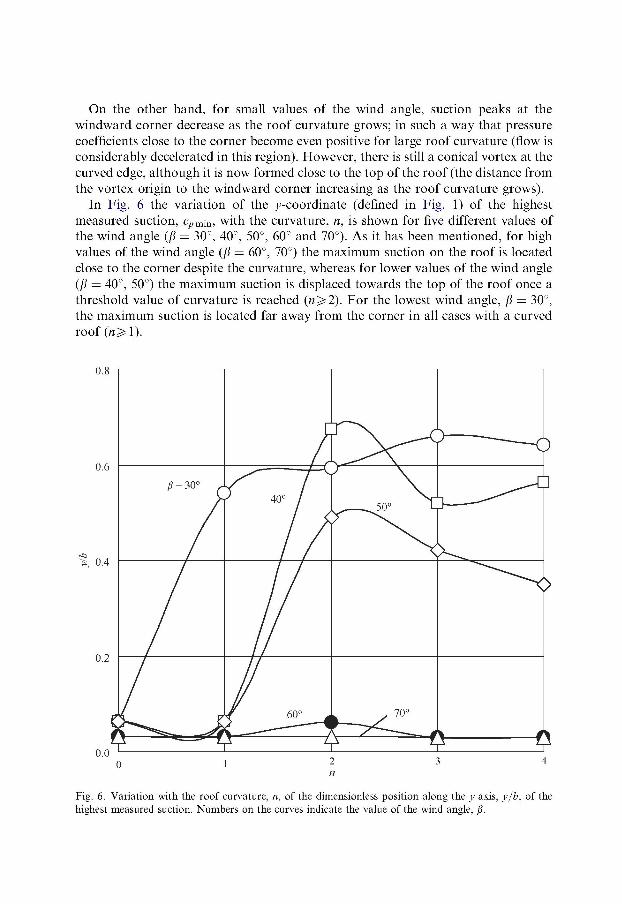
In Fig. 6 the variation of the j-coordinate (denned in Fig. 1) of the highest measured suction, cpm;n, with the curvature, n, is shown for five different values of the wind angle (jft = 30°, 40°, 50°, 60° and 70°). As it has been mentioned, for high values of the wind angle (/? — 60°, 70°) the maximum suction on the roof is located close to the corner despite the curvature, whereas for lower values of the wind angle (/J — 40°, 50°) the maximum suction is displaced towards the top of the roof once a threshold value of curvature is reached (n^2). For the lowest wind angle, \i — 30°, the maximum suction is located far away from the corner in all cases with a curved roof («^ 1).
0.8 I 1 1 1 1
Fig. 6. Variation with the roof curvature, n, of the dimensionless position along the j-axis, y/b, of the highest measured suction. Numbers on the curves indicate the value of the wind angle, /J.
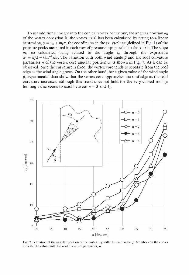
To get additional insight into the conical vortex behaviour, the angular position a0
of the vortex core (that is, the vortex axis) has been calculated by fitting to a linear expression, y — y0 + m$x, the coordinates in the (x, j)-plane (defined in Fig. 1) of the pressure peaks measured in each row of pressure taps parallel to the x-axis. The slope mQ so calculated being related to the angle a,0 through the expression ao — ft/2 — tan - 1 mo. The variation with both wind angle \i and the roof curvature parameter n of the vortex core angular position a0
lS shown in Fig. 7. As it can be observed, once the curvature is fixed, the vortex core tends to separate from the roof edge as the wind angle grows. On the other hand, for a given value of the wind angle jS, experimental data show that the vortex core approaches the roof edge as the roof curvature increases, although this trend does not hold for the very curved roof (a limiting value seems to exist between n — 3 and 4).
30 35 40 45 50 55 60 65 70 75
P [degrees]
Fig. 7. Variation of the angular position of the vortex, a0, with the wind angle, /J. Numbers on the curves indicate the values with the roof curvature parameter, n.

In all the cases where the cantilever parapet was used, it was impossible to determine the vortex angular position because the jet created between the parapet and the roof surface drastically reduces the effect of the vortex on the pressure distribution.
The variation with the angle of incidence, jS, of the minimum pressure coefficients, cpmm, measured on the different roofs is shown in Fig. 8. It can be observed that, in the case of roofs without parapets (solid lines) the magnitude of the suction peak increases as the angle of incidence grows until a maximum is reached at a wind angle jSmax whose value increases as the roof curvature increases. Note that highest suction
r w
f ;:*
n = or
n= 1
J -
n= 1
n = 0 J — s --i |
30 35 40 45 50 55 60 65 70 75 /? [degrees]
Ju — "** ̂ —- L __ r ~|
n = 3s
--i n = 2
n = 2
n = 3 J — F — {. 3 —
30 35 40 45 50 55 60 65 70 75 /? [degrees]
6
5
3C
, C
**
> - T" -4- —" * • V --<
n = 4
n = 4 ^ - < )
30 35 40 45 50 55 60 65 70 75 /? [degrees]
Fig. 8. Variation with the yaw angle of the incident wind, /J, of the highest mean suction, —cpmia, measured on the different roof models (n = 0, 1, 2, 3 and 4). Solid lines correspond to roof without any parapets, whereas dashed ones correspond to roofs with cantilever parapets.
loads (— cprninx6) are reached for planar or almost planar roofs (n — 0, 1), the maximum suction being smaller as the roof becomes more and more curved.
When a cantilever parapet like the one represented in Fig. 3 is added to the windward curved edge, the pressure distributions become rather different, since, as explained above, that cantilever parapets force a plain jet parallel to the roof surface that separates the conical vortex from the roof (Fig. 8). Because of this jet, suction loads are almost constantly irrespective of the value of the wind angle of incidence. Note that cantilever parapets seem to be very effective devices to reduce the highest suction loads on both flat and curved roofs (dashed lines), the reduction load factor being up to 2.4 in the case of flat roofs.
4. Conclusions
Wind-tunnel measurements involving different curved roof configurations were modelled aiming to analyse the influence of roof curvature on the wind mean suction loads caused by conical vortices on curved roofs. In addition, the same roof configurations equipped with cantilevered parapets placed on the windward curved edge of the roofs were tested in order to evaluate the suitability of these devices to reduce wind mean suction loads.
Experimental data indicate that roof curvature modifies both the magnitude of mean suction peaks and their positions on the roof. For /?^55° the suction peaks appear far away from the windward roof corner, but they have similar values to the flat roof at the same wind angle. On the other hand, for large values of the wind angle, say \i> 55°, the pressure peaks, which are located close to the windward corner of the roof, decrease as the roof curvature grows.
Concerning cantilever parapets, experimental results show that these devices produce a very effective reduction of the wind loads on curved roofs, such reduction being, to some extent, independent to the roof curvature. Such behaviour is explained because of the plane jet injected over the roof surface that reduces the effects of conical vortices.
References
[1] C.W. Williams, C.J. Baker, Appraisal of a semi-empirical model for the pressure field beneath roof corner vortices, J. Fluids Struct. 11 (1997) 767-792.
[2] R.J. Kind, Worst suctions near edges of flat rooftops on low-rise buildings, J. Wind Eng. Ind. Aerodyn. 25 (1986)31^17.
[3] H.W. Tieleman, D. Surry, J.X. Lin, Characteristics of mean and fluctuating pressure coefficients under corner (delta wing) vortices, J. Wind Eng. Ind. Aerodyn. 52 (1994) 263-275.
[4] J.D. Ginger, C.W. Letchford, Pressure factor for edge regions on low rise building roofs, J. Wind Eng. Ind. Aerodyn. 54/55 (1995) 337-344.
[5] J.X. Lin, D. Surry, H.W. Tieleman, The distribution of pressure near roof corners of flat roof low buildings, J. Wind Eng. Ind. Aerodyn. 56 (1995) 235-265.
[6] H. Kawai, G. Nishimura, Characteristics of fluctuating suction and conical vortices on a flat roof in oblique flow, J. Wind Eng. Ind. Aerodyn. 60 (1996) 211-225.
[7] C.W. Letchford, R. Marwood, On the influence of v and w component turbulence on roof pressures beneath conical vortices, J. Wind Eng. Ind. Aerodyn. 69-71 (1997) 567-577'.
[8] H. Kawai, Structure of conical vortices related with suction fluctuation on a flat roof in oblique smooth and turbulent flows, J. Wind Eng. Ind. Aerodyn. 69-71 (1997) 579-588.
[9] R. Marwood, C.J. Wood, Conical vortex movement and its effect on roof pressures, J. Wind Eng. Ind. Aerodyn. 69-71 (1997) 589-595.
[10] D. Banks, R.N. Meroney, P.P. Sarkar, Z. Zhao, F. Wu, Flow visualization of conical vortices on flat roofs with simultaneous surface pressure measurement, J. Wind Eng. Ind. Aerodyn. 84 (2000) 65-85.
[11] H.W. Tieleman, D. Surry, K.C. Metha, Full/model scale comparison of surface pressures on the Texas Tech experimental building, J. Wind Eng. Ind. Aerodyn. 61 (1996) 1-23.
[12] H.W. Tieleman, Model/full scale comparison of pressures on the roof of the TTU experimental building, J. Wind Eng. Ind. Aerodyn. 65 (1996) 133-142.
[13] R. Hoxey, A. Robertson, L. Short, The role of corner vortices in the design of structures, Struct. Eng. Int. 1/98 (1998) 50-55.
[14] G. Lythe, D. Surry, Wind loading of flat rooftops with and without parapets, J. Wind Eng. Ind. Aerodyn. 11 (1983)75-94.
[15] A. Baskaran, T. Stathopoulos, Roof corner wind loads and parapet configurations, J. Wind Eng. Ind. Aerodyn. 29 (1988) 79-88.
[16] T. Stathopoulos, R. Marathe, H. Wu, Mean wind pressures on flat roof corners affected by parapets: field and wind tunnel studies, Eng. Struct. 21 (1999) 629-638.
[17] R.J. Kind, Worst suctions near edges of flat rooftops with parapets, J. Wind Eng. Ind. Aerodyn. 31 (1988) 251-264.
[18] S. Pindado, J. Meseguer, Wind tunnel study on the influence of different parapets on the roof pressure distribution of low-rise buildings, J. Wind Eng. Ind. Aerodyn. 91 (2003) 1133-1139.
[19] S. Pindado, J. Meseguer, A. Martinez, S. Franchini, Wind tunnel analysis on the influence of cantilever parapets on the wind loads of curved roofs, in: V.A. Mendes, M. Rahman, C.A. Brebbia (Eds.), Advances in Fluid Mechanics, vol. V, WIT Press, Wessex, 2004, pp. 405^113.
[20] M. Kazakevitch, The aerodynamics of a hangar membrane roof, J. Wind Eng. Ind. Aerodyn. 77-78 (1998) 157-169.
[21] Eurocode 1 (Spanish version), Bases de proyecto y acciones en estructuras, Parte 2-A: Acciones en estructuras, Acciones del viento, UNE-ENV 1991-2-4, AENOR, 1998.
[22] M. Suzuki, K. Tanemoto, T. Maeda, Aerodynamic characteristics of train/vehicles under cross winds, J. Wind Eng. Ind. Aerodyn. 91 (2003) 209-218.
[23] J. Courchesne, A. Laneville, An experimental evaluation of drag coefficient of rectangular cylinders exposed to grid turbulence, J. Fluids Eng. 104 (1982) 523-528.
[24] M.M. Zdravkovich, E. Carelas, Aerodynamics of a covered pedestrian bridge of a trapezoidal section, J. Wind Eng. Ind. Aerodyn. 66 (1997) 141-153.


![Performance of IBA New Conical Shaped Niobium [18O] Water ... · Vienna sept 2010, poster #9, session P13. Table 2: Results Summary Conical 6 Conical 8 Conical 12 Conical 16 Insert](https://img.pdfslide.net/doc/110x75/5f901a7319a03054823be5c3/performance-of-iba-new-conical-shaped-niobium-18o-water-vienna-sept-2010.jpg)