Embed Size (px)
Citation preview
A PARYLENE MEMS FLOW SENSING ARRAY Ellis Meng and Yu-Chong Tai
Department of Electrical Engineering, Caltech Micromachining Lab California Institute of Technology, 136-93, Pasadena, CA 91126, USA
ABSTRACT
We have demonstrated the first parylene MEMS thermal sensor array capable of detecting small flows down to 0.5 µl/min. The device is fabricated using low-temperature parylene/platinum technology and consists of metallic sensors suspended on a membrane over a bulk micromachined silicon channel. For the first time, insightful results from three different methods of flow sensing using a single device are studied and compared. Multi-mode testing using hot film, calorimetric, and time-of-flight techniques at low overheat ratios has been performed. Thus, this device is biocompatible in both construction and operation.
INTRODUCTION Thermal flow sensing techniques have long been popular for their simplicity in both structure and electronic implementation. Despite the well-known problems of sensor drift and dependence on chemical properties of the fluid, interest in thermal sensing for microfluidics applications continues to grow. Recent developments include the use of thermal sensors to determine the thermal properties of the sensed fluid (thermal diffusivity and conductivity) [1, 2].
Using only an array of resistive sensors, it is possible to detect thermal properties as well as operate under multiple sensing methods. The three most popular thermal flow sensing methods are hot-film, calorimetric, and time-of-flight [3-6]. All three methods are implemented and demonstrated in this device.
DESIGN AND FABRICATION A linear array of seven metallic sensing elements is sandwiched in a membrane on one side of a bulk-micromachined channel. The channel dimensions are 1 mm 0.5 mm 8 mm× × and the sensors are spaced 500 µm apart, center-to-center. By utilizing an array layout, it is possible to operate the device in many different modes and determine the flow direction as well as the thermal profile in the fluid. Sensor structure can be seen in Figure 1 and consists of platinum sensing elements embedded in a parylene membrane. Parylene is chosen as the membrane material for its transparency, barrier properties, and biocompatibility. Platinum is also biocompatible and compatible with parylene technology. In addition, it exhibits excellent corrosion and oxidation resistance and is thermally stable over a wide temperature range. Special silicon couplers [7] are also used to make fluidic connections possible to the device.
Figure 1 3D Views of Sensor Construction
The fabrication steps for this multi-mode flow sensing array are shown in Figure 2 and is modified from the original in [8]. All process steps are low-temperature and thus compatible with parylene technology.
Figure 2 Sensor Process Flow
First, thermally oxidized wafers (1.8 µm thick) are covered with a 2 µm thick coating of parylene. Contact openings are made and then sensors are patterned. Successful sensor formation requires special lithography technique to create a two-layer undercut photoresist lift-off mask. A 1000 Å thick platinum film with a 200 Å of Ti/W for adhesion is sputter deposited onto this mask and defined using lift-off. A second layer of protective parylene (4 µm) is deposited over the sensors and the contact pads are selectively uncovered using oxygen plasma etching. These pads are plated with gold using an electroless plating formulation (Stapleton Technologies Inc.) to facilitate packaging the
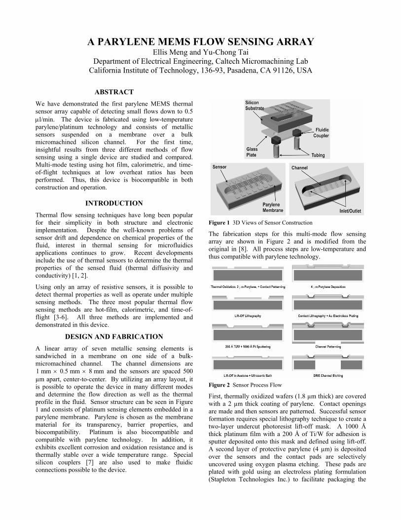
device. On the back side of the wafer, the channel is patterned and etched through to the oxide etch stop using deep reactive ion etching of silicon. The oxide layer is then removed by buffered hydrofluoric acid vapor etching. Individual devices are then separated by dicing.
Figure 3 Fabricated Sensor Array Suspended Over Channel
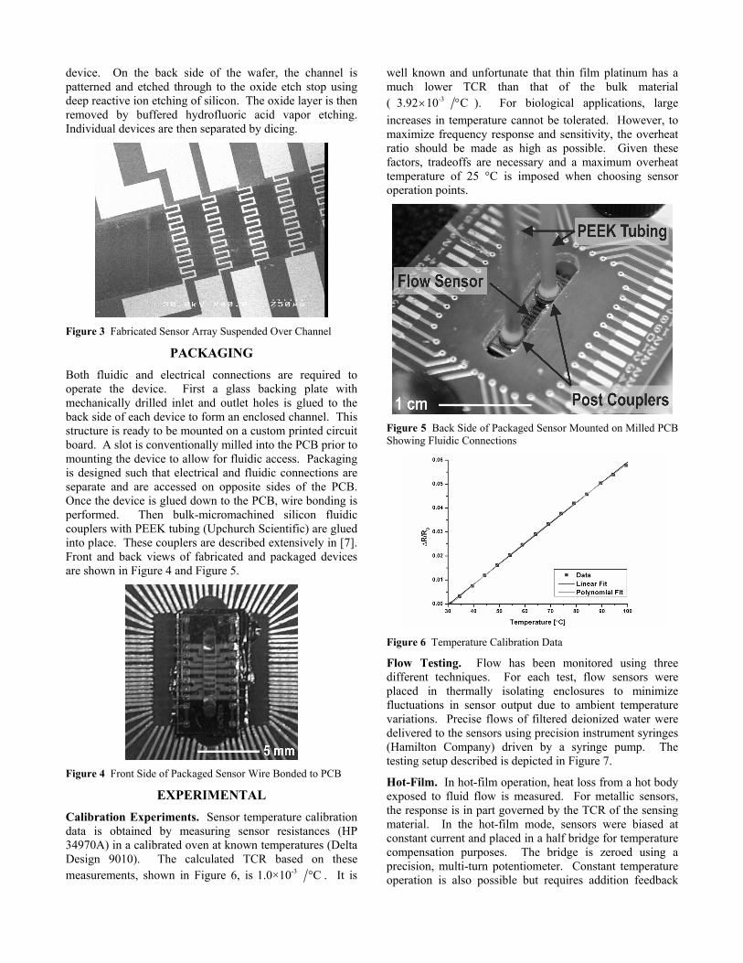
PACKAGING Both fluidic and electrical connections are required to operate the device. First a glass backing plate with mechanically drilled inlet and outlet holes is glued to the back side of each device to form an enclosed channel. This structure is ready to be mounted on a custom printed circuit board. A slot is conventionally milled into the PCB prior to mounting the device to allow for fluidic access. Packaging is designed such that electrical and fluidic connections are separate and are accessed on opposite sides of the PCB. Once the device is glued down to the PCB, wire bonding is performed. Then bulk-micromachined silicon fluidic couplers with PEEK tubing (Upchurch Scientific) are glued into place. These couplers are described extensively in [7]. Front and back views of fabricated and packaged devices are shown in Figure 4 and Figure 5.
Figure 4 Front Side of Packaged Sensor Wire Bonded to PCB
EXPERIMENTAL Calibration Experiments. Sensor temperature calibration data is obtained by measuring sensor resistances (HP 34970A) in a calibrated oven at known temperatures (Delta Design 9010). The calculated TCR based on these measurements, shown in Figure 6, is -31.0×10 °C . It is
well known and unfortunate that thin film platinum has a much lower TCR than that of the bulk material ( -33.92 10 C× ° ). For biological applications, large increases in temperature cannot be tolerated. However, to maximize frequency response and sensitivity, the overheat ratio should be made as high as possible. Given these factors, tradeoffs are necessary and a maximum overheat temperature of 25 °C is imposed when choosing sensor operation points.
Figure 5 Back Side of Packaged Sensor Mounted on Milled PCB Showing Fluidic Connections
Figure 6 Temperature Calibration Data
Flow Testing. Flow has been monitored using three different techniques. For each test, flow sensors were placed in thermally isolating enclosures to minimize fluctuations in sensor output due to ambient temperature variations. Precise flows of filtered deionized water were delivered to the sensors using precision instrument syringes (Hamilton Company) driven by a syringe pump. The testing setup described is depicted in Figure 7.
Hot-Film. In hot-film operation, heat loss from a hot body exposed to fluid flow is measured. For metallic sensors, the response is in part governed by the TCR of the sensing material. In the hot-film mode, sensors were biased at constant current and placed in a half bridge for temperature compensation purposes. The bridge is zeroed using a precision, multi-turn potentiometer. Constant temperature operation is also possible but requires addition feedback
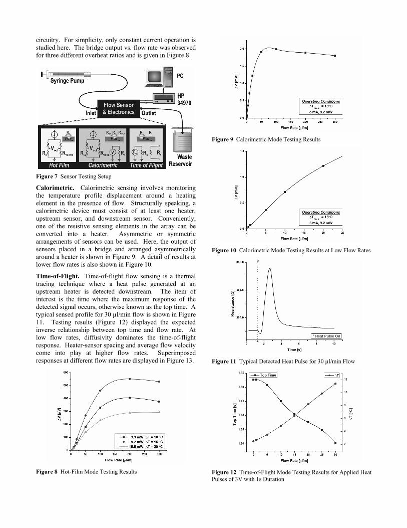
circuitry. For simplicity, only constant current operation is studied here. The bridge output vs. flow rate was observed for three different overheat ratios and is given in Figure 8.
Figure 7 Sensor Testing Setup
Calorimetric. Calorimetric sensing involves monitoring the temperature profile displacement around a heating element in the presence of flow. Structurally speaking, a calorimetric device must consist of at least one heater, upstream sensor, and downstream sensor. Conveniently, one of the resistive sensing elements in the array can be converted into a heater. Asymmetric or symmetric arrangements of sensors can be used. Here, the output of sensors placed in a bridge and arranged asymmetrically around a heater is shown in Figure 9. A detail of results at lower flow rates is also shown in Figure 10.
Time-of-Flight. Time-of-flight flow sensing is a thermal tracing technique where a heat pulse generated at an upstream heater is detected downstream. The item of interest is the time where the maximum response of the detected signal occurs, otherwise known as the top time. A typical sensed profile for 30 µl/min flow is shown in Figure 11. Testing results (Figure 12) displayed the expected inverse relationship between top time and flow rate. At low flow rates, diffusivity dominates the time-of-flight response. Heater-sensor spacing and average flow velocity come into play at higher flow rates. Superimposed responses at different flow rates are displayed in Figure 13.
Figure 8 Hot-Film Mode Testing Results
Figure 9 Calorimetric Mode Testing Results
Figure 10 Calorimetric Mode Testing Results at Low Flow Rates
Figure 11 Typical Detected Heat Pulse for 30 µl/min Flow
Figure 12 Time-of-Flight Mode Testing Results for Applied Heat Pulses of 3V with 1s Duration
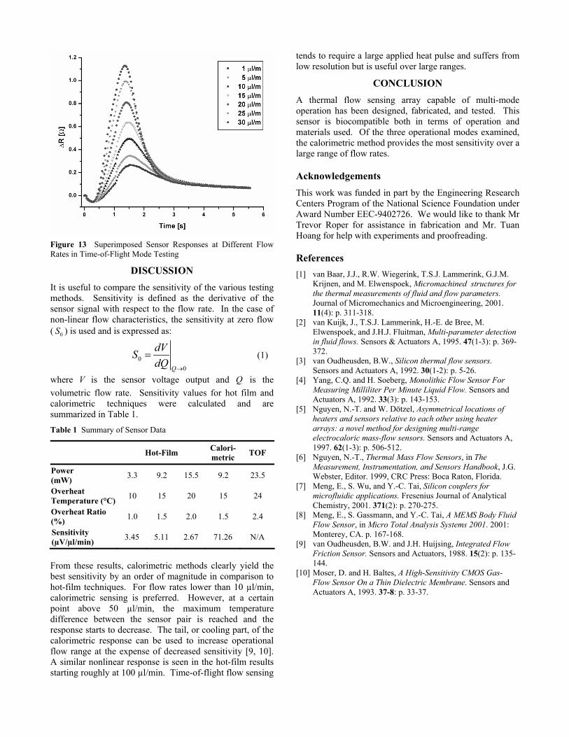
Figure 13 Superimposed Sensor Responses at Different Flow Rates in Time-of-Flight Mode Testing
DISCUSSION It is useful to compare the sensitivity of the various testing methods. Sensitivity is defined as the derivative of the sensor signal with respect to the flow rate. In the case of non-linear flow characteristics, the sensitivity at zero flow ( 0S ) is used and is expressed as:
00Q
dVSdQ →
= (1)
where V is the sensor voltage output and Q is the volumetric flow rate. Sensitivity values for hot film and calorimetric techniques were calculated and are summarized in Table 1.
Table 1 Summary of Sensor Data
Hot-Film Calori-metric TOF
Power (mW) 3.3 9.2 15.5 9.2 23.5
Overheat Temperature (°C) 10 15 20 15 24
Overheat Ratio (%) 1.0 1.5 2.0 1.5 2.4
Sensitivity (µV/µl/min) 3.45 5.11 2.67 71.26 N/A
From these results, calorimetric methods clearly yield the best sensitivity by an order of magnitude in comparison to hot-film techniques. For flow rates lower than 10 µl/min, calorimetric sensing is preferred. However, at a certain point above 50 µl/min, the maximum temperature difference between the sensor pair is reached and the response starts to decrease. The tail, or cooling part, of the calorimetric response can be used to increase operational flow range at the expense of decreased sensitivity [9, 10]. A similar nonlinear response is seen in the hot-film results starting roughly at 100 µl/min. Time-of-flight flow sensing
tends to require a large applied heat pulse and suffers from low resolution but is useful over large ranges.
CONCLUSION A thermal flow sensing array capable of multi-mode operation has been designed, fabricated, and tested. This sensor is biocompatible both in terms of operation and materials used. Of the three operational modes examined, the calorimetric method provides the most sensitivity over a large range of flow rates.
Acknowledgements This work was funded in part by the Engineering Research Centers Program of the National Science Foundation under Award Number EEC-9402726. We would like to thank Mr Trevor Roper for assistance in fabrication and Mr. Tuan Hoang for help with experiments and proofreading.
References [1] van Baar, J.J., R.W. Wiegerink, T.S.J. Lammerink, G.J.M.
Krijnen, and M. Elwenspoek, Micromachined structures for the thermal measurements of fluid and flow parameters. Journal of Micromechanics and Microengineering, 2001. 11(4): p. 311-318.
[2] van Kuijk, J., T.S.J. Lammerink, H.-E. de Bree, M. Elwenspoek, and J.H.J. Fluitman, Multi-parameter detection in fluid flows. Sensors & Actuators A, 1995. 47(1-3): p. 369-372.
[3] van Oudheusden, B.W., Silicon thermal flow sensors. Sensors and Actuators A, 1992. 30(1-2): p. 5-26.
[4] Yang, C.Q. and H. Soeberg, Monolithic Flow Sensor For Measuring Milliliter Per Minute Liquid Flow. Sensors and Actuators A, 1992. 33(3): p. 143-153.
[5] Nguyen, N.-T. and W. Dötzel, Asymmetrical locations of heaters and sensors relative to each other using heater arrays: a novel method for designing multi-range electrocaloric mass-flow sensors. Sensors and Actuators A, 1997. 62(1-3): p. 506-512.
[6] Nguyen, N.-T., Thermal Mass Flow Sensors, in The Measurement, Instrumentation, and Sensors Handbook, J.G. Webster, Editor. 1999, CRC Press: Boca Raton, Florida.
[7] Meng, E., S. Wu, and Y.-C. Tai, Silicon couplers for microfluidic applications. Fresenius Journal of Analytical Chemistry, 2001. 371(2): p. 270-275.
[8] Meng, E., S. Gassmann, and Y.-C. Tai, A MEMS Body Fluid Flow Sensor, in Micro Total Analysis Systems 2001. 2001: Monterey, CA. p. 167-168.
[9] van Oudheusden, B.W. and J.H. Huijsing, Integrated Flow Friction Sensor. Sensors and Actuators, 1988. 15(2): p. 135-144.
[10] Moser, D. and H. Baltes, A High-Sensitivity CMOS Gas-Flow Sensor On a Thin Dielectric Membrane. Sensors and Actuators A, 1993. 37-8: p. 33-37.