Embed Size (px)
Citation preview
J. Micro-Nano Mech. (2009) 5:77–91DOI 10.1007/s12213-010-0026-1
RESEARCH PAPER
A perching mechanism for micro aerial vehicles
Mirko Kovac · Jürg Germann · Christoph Hürzeler ·Roland Y. Siegwart · Dario Floreano
Received: 25 November 2009 / Revised: 21 January 2010 / Accepted: 1 April 2010 / Published online: 4 May 2010© Springer-Verlag 2010
Abstract Micro Aerial Vehicles (MAVs) with perchingcapabilities can be used to efficiently place sensorsin aloft locations. A major challenge for perching isto build a lightweight mechanism that can be easilymounted on a MAV, allowing it to perch (attach anddetach on command) to walls of different materials.To date, only very few systems have been proposedthat aim at enabling MAVs with perching capabilities.Typically, these solutions either require a delicate dy-namic flight maneuver in front of the wall or exposethe MAV to very high impact forces when colliding
Electronic supplementary material The online version of thisarticle (doi:10.1007/s12213-010-0026-1) containssupplementary material, which is availableto authorized users.
M. Kovac (B) · J. Germann · D. FloreanoEcole Polytechnique Fédérale de Lausanne (EPFL),Laboratory of Intelligent Systems (LIS),1015 Lausanne, Switzerlande-mail: [email protected]: http://lis.epfl.ch
J. Germanne-mail: [email protected]
D. Floreanoe-mail: [email protected]
C. Hürzeler · R. Y. SiegwartEidgenössische Technische Hochschule Zürich (ETHZ),Institut für Robotik und Intelligente Systeme (ASL),8092 Zürich, SwitzerlandURL: http://www.asl.ethz.ch
C. Hürzelere-mail: [email protected]
R. Y. Siegwarte-mail: [email protected]
head-first with the wall. In this article, we propose a4.6 g perching mechanism that allows MAVs to perchon walls of natural and man-made materials such astrees and painted concrete facades of buildings. To dothis, no control for the MAV is needed other thanflying head-first into the wall. The mechanism is de-signed to translate the impact impulse into a snappingmovement that sticks small needles into the surfaceand uses a small electric motor to detach from thewall and recharge the mechanism for the next perchingsequence. Based on this principle, it damps the impactforces that act on the platform to avoid damage ofthe MAV. We performed 110 sequential perches on avariety of substrates with a success rate of 100%. Themain contributions of this article are (i) the evaluationof different designs of perching, (ii) the description andformal modeling of a novel perching mechanism, and(iii) the demonstration and characterization of a func-tional prototype on a microglider. (See accompanyingvideo and http://lis.epfl.ch/microglider/perching.mpg.)
1 Introduction
Efficient sensor placement is of crucial importance fordistributed sensor networks, and is necessary for avariety of different scenarios [5, 25, 37]. The challenge ishow to place a large number of sensors in aloft locationswhere they can well monitor the environment. In orderto do that, one possible solution is to equip small MAVswith sensors and the ability to perch to natural and manmade structures. As perching for MAVs we define theability to attach to inclined surfaces or elevated positionsout of f light and detach on command. To date, only very
78 J. Micro-Nano Mech. (2009) 5:77–91
few systems have been demonstrated recently that canattach to surfaces and only one system has been shownto be able to attach to and detach from vertical surfaces.The main difficulty in the design of such a MAV isthat it has to attach to the surface out of flight andsubsequently detach from it to allow a reuse of thesystem or to change its location. All this needs to beachieved while maintaining small size and light weightto be implemented on a MAV.
In this article, we present the development and char-acterization of a working 4.6 g perching mechanism.It allows a small MAV to attach head-first to verticalsurfaces out of flight and detach from them again oncommand using a remote control. To fit the perchingmechanism to different MAVs with different massesand flight velocities and to reduce the impact forceson attachment, we present a mathematical model thatallows to dimension critical components of the mecha-nism. As a test bed to demonstrate the perching mecha-nism being successfully integrated on a MAV, wemount it on a microglider which is a slightly biggerversion of the system presented in [20] and uses compo-nents of the commercially available MicroCeline [38].
Different approaches have been presented to datethat tackle the challenge of perching for MAVs.Anderson et al. [1] recently presented a variety of dif-ferent perching concepts where the best solution con-sists of a small propelled MAV with a mass between 42and 510 g that crashes into the surface at stall speed andadheres to it using liquid glue. It then hangs down on atheater and uses a razor blade to cut the threat to freeitself and retake flight. Although this is a very simpleand innovative design, its main limitation is that theperching can be repeated only as many times as manysticky pads are integrated on the airplane. Ideas aredescribed how to store more than one sticky pad,but have not been implemented yet. The paper men-tions that it can perch successfully, but no systematiccharacterization of the perching capabilities have beenpresented so far. Like other glue based attachmentprinciples, this approach may as well not work on wetor dirty surfaces. Also is the ‘rat-glue’ used on the pre-sented prototype in liquid state and detaches by itselfafter 60 min, limiting the perching time. Dependingon the MAV robustness, this approach may as well belimited to very light weight or slowly flying MAVs asthe impact forces on crash with the wall are directlytranslated to the structure of the MAV. To reduce therisk for structural damage, damping devices or flightmaneuvers would be required to reduce the impactvelocity.
Another project has been recently presented byLussier-Desbiens and Cutkosky [24] where a glider is
flying towards a wall, stalls and attaches to the wallusing microspines. To do this autonomously, it incor-porates an ultrasonic distance range sensor, a completePaparazzi autopilot and suspension which is coveredwith microspines, similar to the ones used in [2].Although this realization can attach to a variety ofmaterials exploiting the surface asperity, it requires arelatively delicate dynamic stall maneuver of the entireMAV and adequate control, which reduces the successrate of attachment to 80% in the current early stageprototype. Detachment has not been demonstrated yetbut could include concepts such as jumping off thesurface or using propellers to reinitiate flight. Theattachment has been demonstrated on a comparablyheavy glider of 400 g, which flies relatively fast at9 m/s. For smaller MAV, such as the very slowlyflying and light weight microglider used in this paper,stalling maneuvers may be even more delicate due tothe low Reynolds number flight regime [27] which isdifficult to control. As well do small or indoor flyingMAVs impose strict weight requirements that do notallow the integration of heavy sensors or complexcomputation [38].
A similar concept has been described by Cory andTedrake [6] who presented a glider that can successfullyand precisely land on a string using a hook as thelanding gear. To be able to do this, the glider is trackedin 3D in a lab environment using a VICON system withsix cameras and is controlled off-board. Wickenheiserand Garcia [35] aim at developing a perching air-craft that changes its tail configuration to deceleratein front of a vertical surface and attach to it. So far,the project has focussed mainly on aerodynamics andcontrol and not on the attachment itself. Bayraktar andFeron [4] recently presented a helicopter that can landon inclined surfaces of up to 60° using velcro on itslanding gear. Analogous to the previous two systems,this helicopter is tracked and controlled externally andhas not been shown to be able to detach by itselfafter landing. Wright and Lind [37] are investigatingsensor placement using a small MAV with morphingwings. The work so far has addressed the computa-tional analysis of the aerodynamics of landing on avertical surface without integrating mechanisms thatwould allow it to actually attach to it. Roberts et al.[31] recently presented a hovering platform that canautonomously attach to and detach from ceilings usingactuated magnets. Its limitation to date is that it onlyworks on horizontal and ferromagnetic ceilings.
Numerous other projects deal with the challenge ofattachment and detachment from the perspective of ap-plying it to climbing robots. All these systems howeverare not designed to fly and they have the tendency to
J. Micro-Nano Mech. (2009) 5:77–91 79
Tab
le1
Com
pari
son
ofdi
ffer
enta
dhes
ion
met
hods
for
the
appl
icat
ion
tope
rchi
ngro
bots
Adh
esio
nm
etho
dW
orki
ngpr
inci
ple
Adv
anta
ges
Lim
itat
ions
Synt
heti
cge
cko
Synt
heti
cse
tae
crea
tea
larg
eco
ntac
tW
orks
ona
vari
ety
ofsu
bstr
ates
,D
oes
notw
ork
ondu
sty
and
dirt
ysu
rfac
es,a
dhes
ion
tape
[3,9
,10,
26]
surf
ace
wit
hth
esu
bstr
ate
and
adhe
redi
rect
iona
ladh
esio
n,lig
htw
eigh
t,de
pend
sst
rong
lyon
roug
hnes
sof
subs
trat
e,to
date
base
don
van
der
Waa
lsfo
rces
.no
ener
gyco
nsum
ptio
non
lyve
rylim
ited
life
tim
e,di
ffic
ultf
abri
cati
onpr
oces
s,pr
eloa
dfo
rce
requ
ired
,det
achm
entr
equi
res
peel
ing
Glu
e[1
,7]
Che
mic
alad
hesi
onE
asy
com
mer
cial
avai
labi
lity,
wor
ksD
oes
notw
ork
ondu
sty
and
dirt
ysu
rfac
es,d
epen
danc
eon
ava
riet
yof
subs
trat
es,l
ight
wei
ght,
onro
ughn
ess
ofm
ater
ial,
limit
edlif
etim
e,pr
eloa
dfo
rce
noen
ergy
cons
umpt
ion,
depe
ndin
gre
quir
ed,d
etac
hmen
treq
uire
spe
elin
gor
the
loss
onm
ater
ial,
very
stro
ngad
hesi
onof
the
stic
kypa
dSu
ctio
ncu
ps[2
2,30
]V
acuu
mcr
eate
sfo
rce
toSt
rong
forc
eon
smoo
thsu
rfac
es,
Wor
kson
lyon
smoo
thsu
rfac
es,d
oes
notw
ork
wel
lon
dust
yho
ldit
onth
esu
rfac
ew
orks
ona
vari
ety
ofsu
bstr
ates
ordi
rty
surf
aces
,req
uire
sa
mec
hani
smto
crea
teth
eva
cuum
,de
vice
sto
date
are
rela
tive
lybu
lky
and
heav
yM
agne
ts[3
1,33
]M
agne
tic
forc
eV
ery
stro
ngfo
rce,
easy
com
mer
cial
avai
labi
lity,
Wor
kson
lyon
ferr
omag
neti
cm
ater
ials
nopr
eloa
dfo
rce
requ
ired
toat
tach
,lig
htw
eigh
t,no
ener
gyco
nsum
ptio
nE
lect
road
hesi
on[2
8]E
lect
rost
atic
attr
acti
onR
elat
ivel
yst
rong
adhe
sion
,wor
kson
dust
yR
equi
res
asm
alla
mou
ntof
ener
gyto
stay
atta
ched
,an
ddi
rty
surf
aces
,wor
kson
aw
orks
only
onsm
ooth
surf
aces
vari
ety
ofsu
bstr
ates
Mic
rosp
ines
(wit
hout
Smal
lspi
nes
acta
sho
oks
toat
tach
No
ener
gyco
nsum
ptio
n,D
irec
tion
alad
hesi
on,
Doe
sno
twor
kon
very
smoo
thor
very
roug
hsu
rfac
es,
pene
trat
ion
into
the
toro
ughn
ess
onth
esu
rfac
ew
orks
ona
vari
ety
ofsu
bstr
ates
,di
rect
iona
lmov
emen
treq
uire
dto
deta
chsu
bstr
ate)
[2,8
,24]
nopr
eloa
dfo
rce
requ
ired
toat
tach
Cla
ws
[36]
Gra
spin
gon
toco
arse
stru
ctur
esW
orks
ona
vari
ety
ofsu
bstr
ates
,W
orks
only
onve
ryro
ugh
surf
aces
,dep
ends
onfr
icti
onon
the
surf
ace
pote
ntia
llyhi
ghad
hesi
onth
roug
hof
the
subs
trat
em
echa
nica
lclin
ging
Pen
etra
tion
base
d[2
9]U
sing
need
les
orsp
ines
toW
orks
onsm
ooth
and
roug
hsu
rfac
es,
Wor
ksup
toa
cert
ain
hard
ness
ofth
esu
bstr
ate,
pene
trat
eth
esu
bstr
ate
wor
kson
diff
eren
tsub
stra
tes,
leav
essm
allh
oles
inth
esu
rfac
eea
syco
mm
erci
alav
aila
bilit
yof
the
need
les,
sim
ple
prin
cipl
ean
dea
syto
use,
wor
kson
dust
yan
ddi
rty
surf
aces
,no
ener
gyco
nsum
ptio
n
80 J. Micro-Nano Mech. (2009) 5:77–91
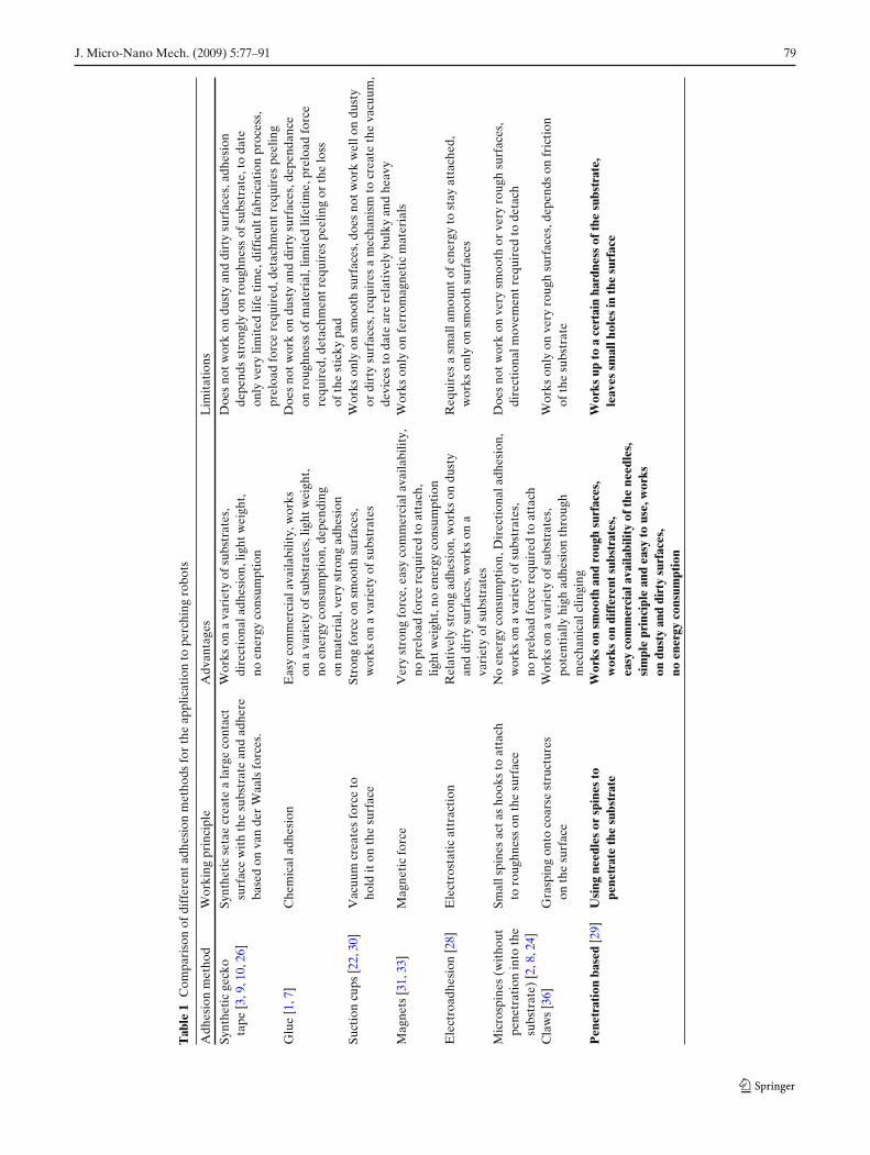
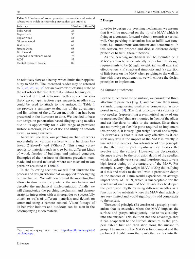
Table 2 Hardness of some prevalent man-made and naturalsubstrates to which our perching mechanism can attach to
Substrate Hardness [ShoreD]
Balsa wood 24Poplar bark 36Poplar wood 54Okuome wood 61Wallpaper 62Spruce wood 65Birch wood 69Composite hardboard wood 76MDF 87Painted concrete facade 89
be relatively slow and heavy, which limits their applica-bility to MAVs. The interested reader may be referredto [2, 26, 28, 32, 36] for an overview of existing state ofthe art robots that use different climbing techniques.
Several different adhesion methods, such as syn-thetic gecko tape, suction cups, magnets, needles etc.,could be used to attach to the surface. In Table 1we provide a summary evaluation of the advantagesand limitations of the different methods that has beenpresented in the literature to date. We decided to baseour design on penetration based clinging using needlesdue to its applicability for a wide range of prevalentsurface materials, its ease of use and utility on smoothas well as rough surfaces.
As we will see later, our perching mechanism workssuccessfully on vertical surfaces with a hardness be-tween 24ShoreD and 89ShoreD. This range corre-sponds to materials such as tree barks, different kindsof wood, facades of buildings and painted concrete.Examples of the hardness of different prevalent man-made and natural materials where our mechanism canperch on are listed in Table 2.
In the following sections we will first illustrate theprocess and design criteria that we applied for designingour mechanism. We will then present the modeling thatallows to dimension the parts of the mechanism anddescribe the mechanical implementation. Finally, wewill characterize the perching mechanism and demon-strate its integration with a microglider to successfullyattach to walls of different materials and detach oncommand using a remote control. Video footage ofits behavior indoors and outdoors can be seen in theaccompanying video material.1
1See accompanying video and http://lis.epfl.ch/microglider/perching.mpg.
2 Design
In order to design our perching mechanism, we assumethat it will be mounted on the tip of a MAV which isflying at a constant forward velocity towards a verticalwall. Our perching mechanism has to fulfill two func-tions, i.e. autonomous attachment and detachment. Inthis section, we propose and discuss different designprinciples to fulfill these functions.
As the perching mechanism will be mounted on aMAV and has to work robustly, we define the designrequirements to be (i) light weight, (ii) small size, (iii)effectiveness, (iv) structural simplicity and (v) exertionof little force on the MAV when perching to the wall. Inline with these requirements, we will choose the designprinciples to implement.
2.1 Surface attachment
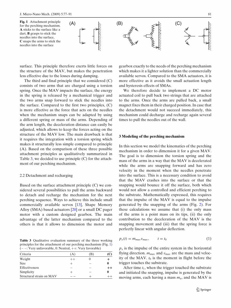
For the attachment to the surface, we considered threeattachment principles (Fig. 1) and compare them usinga standard engineering qualitative comparison as pro-posed in e.g. [34]. The first principle (A) consists oftwo needles (representing a symmetrical array of oneor more needles) that are mounted in front of the gliderand act like darts to stick to the surface. Since thereare no moving or flexible parts required to implementthis principle, it is very light weight, small and simple.Its drawback is that it is not very effective as it canstick only well if the impact of the MAV is exactly inline with the needles. An advantage of this principleis that the entire impact impulse is used to stick theneedles into the surface. However, the decelerationdistance is given by the protrusion depth of the needles,which is typically very short and therefore leads to veryhigh forces acting on the structure of the MAV. Forexample, a very light weight MAV of 20 g that is flyingat 4 m/s and sticks to the wall with a protrusion depthof the needles of 1 mm would experience an averageimpact force of 160 N, which is unacceptable for thestructure of such a small MAV. Possibilities to deepenthe protrusion depth by using different needles as afunction of the substrate where the MAV shall attach toare very limited and would significantly add complexityto the system.
The second principle (B) consists of a grasping mech-anism that is extended when the MAV impacts thesurface and grasps subsequently, due to its elasticity,into the surface. This solution has the advantage thatit can adapt well to the surface structure as the grip-pers extend first and then slide along the surface tograsp. The impact of the MAVs is first damped and thepreloaded flexible arms then push the needles into the
J. Micro-Nano Mech. (2009) 5:77–91 81
Fig. 1 Attachment principlefor the perching mechanism.A sticks to the surface like adart, B grasps to stick theneedles into the surface,C snaps the arms to stick theneedles into the surface
(C)(B)(A)
surface. This principle therefore exerts little forces onthe structure of the MAV, but makes the penetrationless effective due to the losses during damping.
The third and final principle that we considered (C)consists of two arms that are charged using a torsionspring. Once the MAV impacts the surface, the energyin the spring is released by a mechanical trigger andthe two arms snap forward to stick the needles intothe surface. Compared to the first two principles, (C)is more effective as the force that acts on the needleswhen the mechanism snaps can be adapted by usinga different spring or mass of the arms. Depending ofthe arm length, the deceleration distance can easily beadjusted, which allows to keep the forces acting on thestructure of the MAV low. The main drawback is thatit requires the integration with a torsion spring whichmakes it structurally less simple compared to principle(A). Based on the comparison of these three possibleattachment principles as qualitatively summarized inTable 3, we decided to use principle (C) for the attach-ment of our perching mechanism.
2.2 Detachment and recharging
Based on the surface attachment principle (C) we con-sidered several possibilities to pull the arms backwardto detach and recharge the mechanism for the nextperching sequence. Ways to achieve this include smallcommercially available servos [13], Shape MemoryAlloy (SMA) based actuators [20] or a small DC pagermotor with a custom designed gearbox. The mainadvantage of the latter mechanism compared to theothers is that it allows to dimension the motor and
Table 3 Qualitative evaluation summary of the three workingprinciples for the attachment of our perching mechanism (Fig. 1)(− −: Very unfavorable, 0: Neutral, ++: Very favorable)
Criteria (A) (B) (C)
Weight ++ 0 +Size + − 0Effectiveness − − ++Simplicity + − 0Structural strain on MAV − − + ++
gearbox exactly to the needs of the perching mechanismwhich makes it a lighter solution than the commerciallyavailable servos. Compared to the SMA actuators, it ismore effective as it avoids the small actuation lengthand hysteresis effects of SMAs.
We therefore decide to implement a DC motoractuated coil to pull back two strings that are attachedto the arms. Once the arms are pulled back, a smallmagnet fixes them in their charged position. In case thatthe detachment would not succeed immediately, thismechanism could decharge and recharge again severaltimes to pull the needles out of the wall.
3 Modeling of the perching mechanism
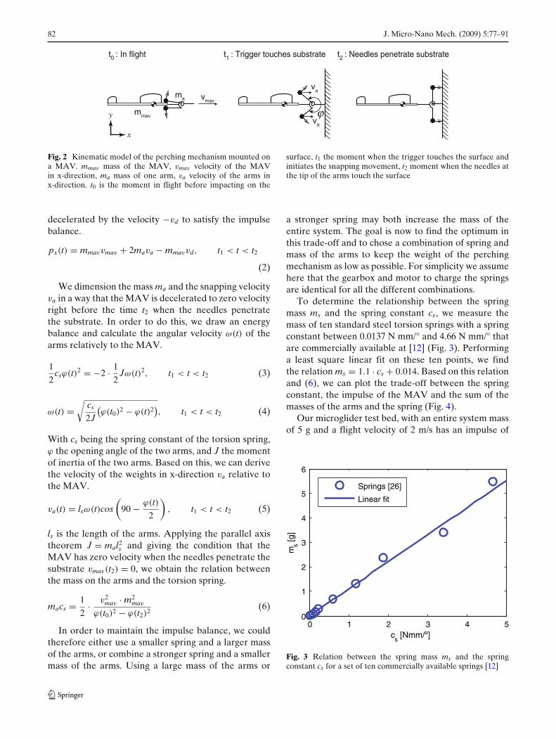
In this section we model the kinematics of the perchingmechanism in order to dimension it for a given MAV.The goal is to dimension the torsion spring and themass of the arms in a way that the MAV is deceleratedwhile the arms are snapping forward and has zerovelocity in the moment when the needles penetrateinto the surface. This is a necessary condition to avoidthat the MAV crashes into the surface or that thesnapping would bounce it off the surface, both whichwould not allow a controlled and efficient perching tothe substrate. Mathematically expressed, this requiresthat the impulse of the MAV is equal to the impulsegenerated by the snapping of the arms (Fig. 2). Forthese calculations we assume that (i) the only massof the arms is a point mass on its tips, (ii) the onlycontribution to the deceleration of the MAV is thesnapping movement and (iii) that the spring force isperfectly linear with angular deflection.
px(t) = mmavvmav, t = t0 (1)
px is the impulse of the entire system in the horizontalflying direction. mmav and vmav are the mass and veloc-ity of the MAV. t0 is the moment in flight before thetrigger touches the substrate.
After time t1, when the trigger touched the substrateand initiated the snapping, impulse is generated by themoving arms, each having a mass ma, and the MAV is
82 J. Micro-Nano Mech. (2009) 5:77–91
mmav
vmavma
va
vϕa
t0 : In flight t1 : Trigger touches substrate t2 : Needles penetrate substrate
x
y
Fig. 2 Kinematic model of the perching mechanism mounted ona MAV. mmav mass of the MAV, vmav velocity of the MAVin x-direction, ma mass of one arm, va velocity of the arms inx-direction. t0 is the moment in flight before impacting on the
surface, t1 the moment when the trigger touches the surface andinitiates the snapping movement, t2 moment when the needles atthe tip of the arms touch the surface
decelerated by the velocity −vd to satisfy the impulsebalance.
px(t) = mmavvmav + 2mava − mmavvd, t1 < t < t2
(2)
We dimension the mass ma and the snapping velocityva in a way that the MAV is decelerated to zero velocityright before the time t2 when the needles penetratethe substrate. In order to do this, we draw an energybalance and calculate the angular velocity ω(t) of thearms relatively to the MAV.
12
csϕ(t)2 = −2 · 12
Jω(t)2, t1 < t < t2 (3)
ω(t) =√
cs
2J
(ϕ(t0)2 − ϕ(t)2
), t1 < t < t2 (4)
With cs being the spring constant of the torsion spring,ϕ the opening angle of the two arms, and J the momentof inertia of the two arms. Based on this, we can derivethe velocity of the weights in x-direction va relative tothe MAV.
va(t) = lsω(t)cos(
90 − ϕ(t)2
), t1 < t < t2 (5)
ls is the length of the arms. Applying the parallel axistheorem J = mal2
s and giving the condition that theMAV has zero velocity when the needles penetrate thesubstrate vmav(t2) = 0, we obtain the relation betweenthe mass on the arms and the torsion spring.
macs = 12
· v2mav · m2
mav
ϕ(t0)2 − ϕ(t2)2 (6)
In order to maintain the impulse balance, we couldtherefore either use a smaller spring and a larger massof the arms, or combine a stronger spring and a smallermass of the arms. Using a large mass of the arms or
a stronger spring may both increase the mass of theentire system. The goal is now to find the optimum inthis trade-off and to chose a combination of spring andmass of the arms to keep the weight of the perchingmechanism as low as possible. For simplicity we assumehere that the gearbox and motor to charge the springsare identical for all the different combinations.
To determine the relationship between the springmass ms and the spring constant cs, we measure themass of ten standard steel torsion springs with a springconstant between 0.0137 N mm/° and 4.66 N mm/° thatare commercially available at [12] (Fig. 3). Performinga least square linear fit on these ten points, we findthe relation ms = 1.1 · cs + 0.014. Based on this relationand (6), we can plot the trade-off between the springconstant, the impulse of the MAV and the sum of themasses of the arms and the spring (Fig. 4).
Our microglider test bed, with an entire system massof 5 g and a flight velocity of 2 m/s has an impulse of
0 1 2 3 4 50
1
2
3
4
5
6
cs [Nmm/º]
ms [g
]
Springs [26]
Linear fit
Fig. 3 Relation between the spring mass ms and the springconstant cs for a set of ten commercially available springs [12]
J. Micro-Nano Mech. (2009) 5:77–91 83
0 0.1 0.2 0.3 0.4 0
10
200
1
2
3
pmav
[mNs]c
s [Nmm/°]
(ms +
2m
a) [g
]Satisfy the impulse balance (equ. 6)
For mmav
=5g and vmav
=2m/s
Chosen combination
minimal weight forour microglider
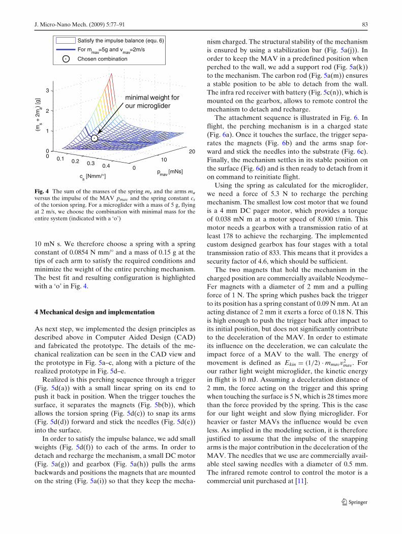
Fig. 4 The sum of the masses of the spring ms and the arms maversus the impulse of the MAV pmav and the spring constant csof the torsion spring. For a microglider with a mass of 5 g, flyingat 2 m/s, we choose the combination with minimal mass for theentire system (indicated with a ‘o’)
10 mN s. We therefore choose a spring with a springconstant of 0.0854 N mm/° and a mass of 0.15 g at thetips of each arm to satisfy the required conditions andminimize the weight of the entire perching mechanism.The best fit and resulting configuration is highlightedwith a ‘o’ in Fig. 4.
4 Mechanical design and implementation
As next step, we implemented the design principles asdescribed above in Computer Aided Design (CAD)and fabricated the prototype. The details of the me-chanical realization can be seen in the CAD view andthe prototype in Fig. 5a–c, along with a picture of therealized prototype in Fig. 5d–e.
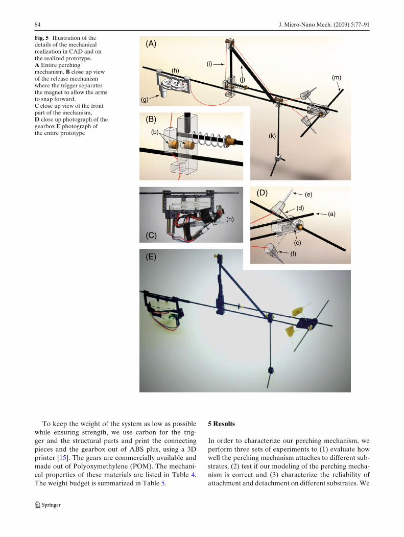
Realized is this perching sequence through a trigger(Fig. 5d(a)) with a small linear spring on its end topush it back in position. When the trigger touches thesurface, it separates the magnets (Fig. 5b(b)), whichallows the torsion spring (Fig. 5d(c)) to snap its arms(Fig. 5d(d)) forward and stick the needles (Fig. 5d(e))into the surface.
In order to satisfy the impulse balance, we add smallweights (Fig. 5d(f)) to each of the arms. In order todetach and recharge the mechanism, a small DC motor(Fig. 5a(g)) and gearbox (Fig. 5a(h)) pulls the armsbackwards and positions the magnets that are mountedon the string (Fig. 5a(i)) so that they keep the mecha-
nism charged. The structural stability of the mechanismis ensured by using a stabilization bar (Fig. 5a(j)). Inorder to keep the MAV in a predefined position whenperched to the wall, we add a support rod (Fig. 5a(k))to the mechanism. The carbon rod (Fig. 5a(m)) ensuresa stable position to be able to detach from the wall.The infra red receiver with battery (Fig. 5c(n)), which ismounted on the gearbox, allows to remote control themechanism to detach and recharge.
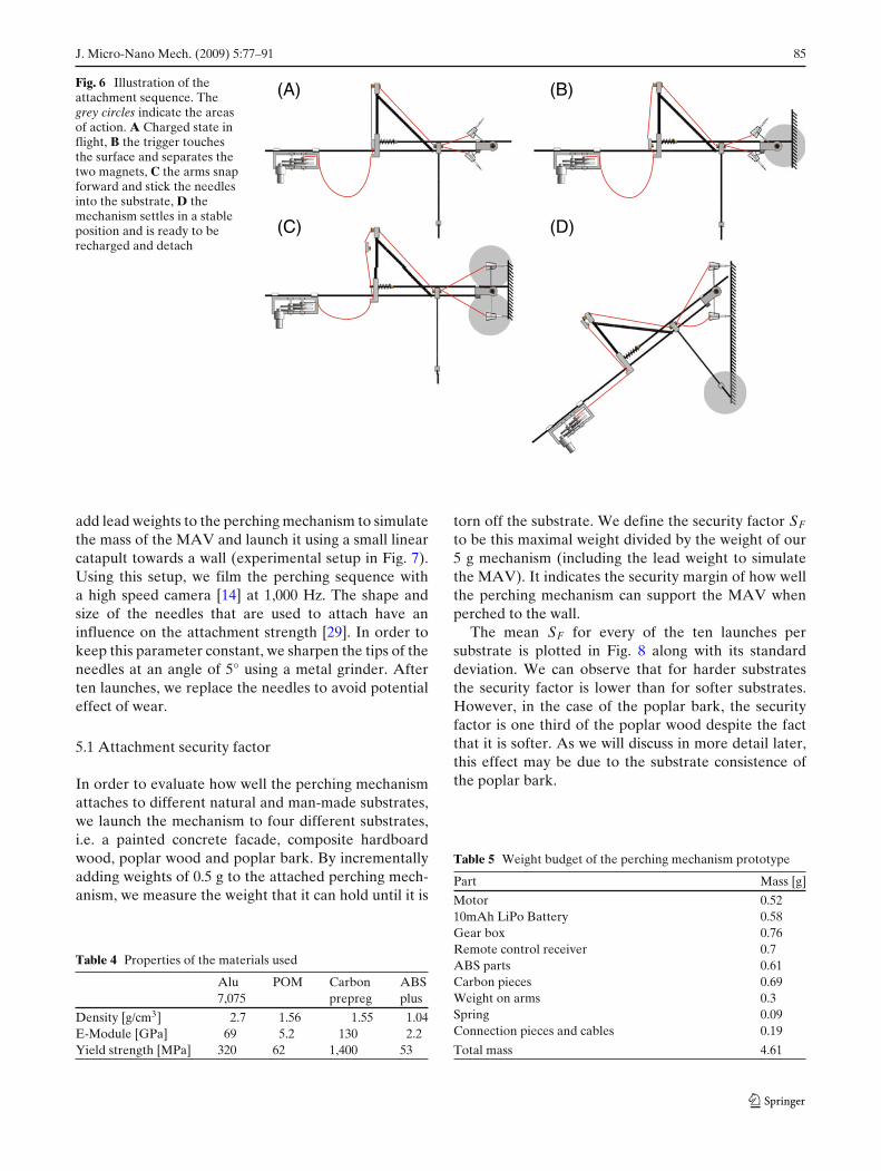
The attachment sequence is illustrated in Fig. 6. Inflight, the perching mechanism is in a charged state(Fig. 6a). Once it touches the surface, the trigger sepa-rates the magnets (Fig. 6b) and the arms snap for-ward and stick the needles into the substrate (Fig. 6c).Finally, the mechanism settles in its stable position onthe surface (Fig. 6d) and is then ready to detach from iton command to reinitiate flight.
Using the spring as calculated for the microglider,we need a force of 5.3 N to recharge the perchingmechanism. The smallest low cost motor that we foundis a 4 mm DC pager motor, which provides a torqueof 0.038 mN m at a motor speed of 8,000 t/min. Thismotor needs a gearbox with a transmission ratio of atleast 178 to achieve the recharging. The implementedcustom designed gearbox has four stages with a totaltransmission ratio of 833. This means that it provides asecurity factor of 4.6, which should be sufficient.
The two magnets that hold the mechanism in thecharged position are commercially available Neodyme–Fer magnets with a diameter of 2 mm and a pullingforce of 1 N. The spring which pushes back the triggerto its position has a spring constant of 0.09 N mm. At anacting distance of 2 mm it exerts a force of 0.18 N. Thisis high enough to push the trigger back after impact toits initial position, but does not significantly contributeto the deceleration of the MAV. In order to estimateits influence on the deceleration, we can calculate theimpact force of a MAV to the wall. The energy ofmovement is defined as Ekin = (1/2) · mmavv
2mav . For
our rather light weight microglider, the kinetic energyin flight is 10 mJ. Assuming a deceleration distance of2 mm, the force acting on the trigger and this springwhen touching the surface is 5 N, which is 28 times morethan the force provided by the spring. This is the casefor our light weight and slow flying microglider. Forheavier or faster MAVs the influence would be evenless. As implied in the modeling section, it is thereforejustified to assume that the impulse of the snappingarms is the major contribution in the deceleration of theMAV. The needles that we use are commercially avail-able steel sawing needles with a diameter of 0.5 mm.The infrared remote control to control the motor is acommercial unit purchased at [11].
84 J. Micro-Nano Mech. (2009) 5:77–91
Fig. 5 Illustration of thedetails of the mechanicalrealization in CAD and onthe realized prototype.A Entire perchingmechanism, B close up viewof the release mechanismwhere the trigger separatesthe magnet to allow the armsto snap forward,C close up view of the frontpart of the mechanism,D close up photograph of thegearbox E photograph ofthe entire prototype
(A)
(B)
(D)
(g)
(h)(i)
(j) (m)
(k)
(e)
(d)(a)
(c)
(f)
(b)
(n)
(C)
(E)
To keep the weight of the system as low as possiblewhile ensuring strength, we use carbon for the trig-ger and the structural parts and print the connectingpieces and the gearbox out of ABS plus, using a 3Dprinter [15]. The gears are commercially available andmade out of Polyoxymethylene (POM). The mechani-cal properties of these materials are listed in Table 4.The weight budget is summarized in Table 5.
5 Results
In order to characterize our perching mechanism, weperform three sets of experiments to (1) evaluate howwell the perching mechanism attaches to different sub-strates, (2) test if our modeling of the perching mecha-nism is correct and (3) characterize the reliability ofattachment and detachment on different substrates. We
J. Micro-Nano Mech. (2009) 5:77–91 85
Fig. 6 Illustration of theattachment sequence. Thegrey circles indicate the areasof action. A Charged state inflight, B the trigger touchesthe surface and separates thetwo magnets, C the arms snapforward and stick the needlesinto the substrate, D themechanism settles in a stableposition and is ready to berecharged and detach
(A)
(C)
(B)
(D)
add lead weights to the perching mechanism to simulatethe mass of the MAV and launch it using a small linearcatapult towards a wall (experimental setup in Fig. 7).Using this setup, we film the perching sequence witha high speed camera [14] at 1,000 Hz. The shape andsize of the needles that are used to attach have aninfluence on the attachment strength [29]. In order tokeep this parameter constant, we sharpen the tips of theneedles at an angle of 5° using a metal grinder. Afterten launches, we replace the needles to avoid potentialeffect of wear.
5.1 Attachment security factor
In order to evaluate how well the perching mechanismattaches to different natural and man-made substrates,we launch the mechanism to four different substrates,i.e. a painted concrete facade, composite hardboardwood, poplar wood and poplar bark. By incrementallyadding weights of 0.5 g to the attached perching mech-anism, we measure the weight that it can hold until it is
Table 4 Properties of the materials used
Alu POM Carbon ABS7,075 prepreg plus
Density [g/cm3] 2.7 1.56 1.55 1.04E-Module [GPa] 69 5.2 130 2.2Yield strength [MPa] 320 62 1,400 53
torn off the substrate. We define the security factor SF
to be this maximal weight divided by the weight of our5 g mechanism (including the lead weight to simulatethe MAV). It indicates the security margin of how wellthe perching mechanism can support the MAV whenperched to the wall.
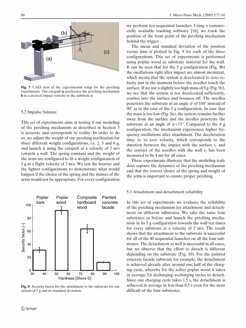
The mean SF for every of the ten launches persubstrate is plotted in Fig. 8 along with its standarddeviation. We can observe that for harder substratesthe security factor is lower than for softer substrates.However, in the case of the poplar bark, the securityfactor is one third of the poplar wood despite the factthat it is softer. As we will discuss in more detail later,this effect may be due to the substrate consistence ofthe poplar bark.
Table 5 Weight budget of the perching mechanism prototype
Part Mass [g]
Motor 0.5210mAh LiPo Battery 0.58Gear box 0.76Remote control receiver 0.7ABS parts 0.61Carbon pieces 0.69Weight on arms 0.3Spring 0.09Connection pieces and cables 0.19
Total mass 4.61
86 J. Micro-Nano Mech. (2009) 5:77–91
(a)
(b)
(c)
Fig. 7 CAD view of the experimental setup for the perchingexperiments. The catapult a accelerates the perching mechanismb to a desired impact velocity to the substrate c
5.2 Impulse balance
This set of experiments aims at testing if our modelingof the perching mechanism as described in Section 3is accurate and corresponds to reality. In order to doso, we adjust the weight of our perching mechanism forthree different weight configurations, i.e. 2, 5 and 8 g,and launch it using the catapult at a velocity of 2 m/stowards a wall. The spring constant and the weight ofthe arms are configured to fit a weight configuration of5 g at a flight velocity of 2 m/s. We test the heavier andthe lighter configurations to demonstrate what wouldhappen if the choice of the spring and the masses of thearms would not be appropriate. For every configuration
30 40 50 60 70 80 90 1000
20
40
60
80
100
Hardness [Shore D]
Painted concrete facade
Composite hardboard wood
Poplar wood
Poplar bark
Sec
urity
fact
or [–
]
Fig. 8 Security factor for the attachment to the substrate for oursystem of 5 g and its standard deviation
we perform ten sequential launches. Using a commer-cially available tracking software [16], we track theposition of the front point of the perching mechanismbehind the trigger.
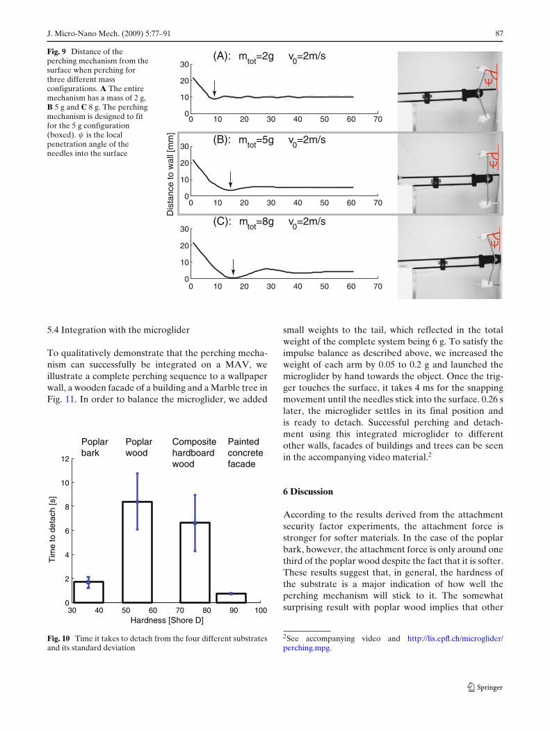
The mean and standard deviation of the positionversus time is plotted in Fig. 9 for each of the threeconfigurations. This set of experiments is performedusing poplar wood as substrate material for the wall.It can be seen that for the 5 g configuration (Fig. 9b)the oscillations right after impact are almost inexistent,which means that the system is decelerated to zero ve-locity just in the moment before the needles touch thesurface. If we use a slightly too high mass of 8 g (Fig. 9c),we see that the system is not decelerated sufficiently,crashes into the surface and bounces off. The needlespenetrate the substrate at an angle ψ of 104° instead of90° as in the case of the 5 g configuration. In case thatthe mass is too low (Fig. 9a), the system remains furtheraway from the surface and the needles penetrate thesubstrate at an angle of ψ=73°. Compared to the 8 gconfiguration, the mechanism experiences higher fre-quency oscillations after attachment. The decelerationtime �t to zero velocity, which corresponds to theduration between the impact with the surface t1 andthe contact of the needles with the wall t2 has beenmeasured to be 4 ms for all cases.
These experiments illustrate that the modeling trulydoes capture the dynamics of the perching mechanismand that the correct choice of the spring and weight ofthe arms is important to ensure proper perching.
5.3 Attachment and detachment reliability
In this set of experiments we evaluate the reliabilityof the perching mechanism for attachment and detach-ment on different substrates. We take the same foursubstrates as before and launch the perching mecha-nism in its 5 g configuration towards the wall ten timesfor every substrate at a velocity of 2 m/s. The resultshows that the attachment to the substrate is successfulfor all of the 40 sequential launches on all the four sub-strates. The detachment as well is successful in all cases,but we observe that the effort to detach is differentdepending on the substrate (Fig. 10). For the paintedconcrete facade substrate for example, the detachmentis achieved already after around one half of the charg-ing cycle, whereby for the softer poplar wood it takesin average 5.6 decharging–recharging cycles to detach.Since one charging cycle takes 1.5 s, the detachment isachieved in average in less than 8.5 s even for the mostdifficult of the four substrates.
J. Micro-Nano Mech. (2009) 5:77–91 87
Fig. 9 Distance of theperching mechanism from thesurface when perching forthree different massconfigurations. A The entiremechanism has a mass of 2 g,B 5 g and C 8 g. The perchingmechanism is designed to fitfor the 5 g configuration(boxed). ψ is the localpenetration angle of theneedles into the surface
0 10 20 30 40 50 60 700
10
20
30
0 10 20 30 40 50 60 700
10
20
30
Dis
tanc
e to
wal
l [m
m]
0 10 20 30 40 50 60 700
10
20
30
(A): mtot=2g v0=2m/s
(B): mtot=5g v0=2m/s
(C): mtot=8g v0=2m/s
5.4 Integration with the microglider
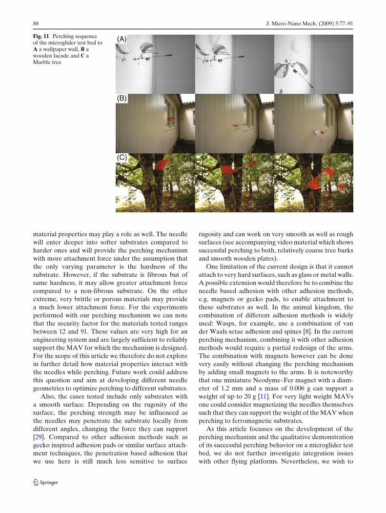
To qualitatively demonstrate that the perching mecha-nism can successfully be integrated on a MAV, weillustrate a complete perching sequence to a wallpaperwall, a wooden facade of a building and a Marble tree inFig. 11. In order to balance the microglider, we added
Painted concrete facade
Composite hardboard wood
Poplar wood
Poplar bark
30 40 50 60 70 80 90 1000
2
4
6
8
10
12
Hardness [Shore D]
Tim
e to
det
ach
[s]
Fig. 10 Time it takes to detach from the four different substratesand its standard deviation
small weights to the tail, which reflected in the totalweight of the complete system being 6 g. To satisfy theimpulse balance as described above, we increased theweight of each arm by 0.05 to 0.2 g and launched themicroglider by hand towards the object. Once the trig-ger touches the surface, it takes 4 ms for the snappingmovement until the needles stick into the surface. 0.26 slater, the microglider settles in its final position andis ready to detach. Successful perching and detach-ment using this integrated microglider to differentother walls, facades of buildings and trees can be seenin the accompanying video material.2
6 Discussion
According to the results derived from the attachmentsecurity factor experiments, the attachment force isstronger for softer materials. In the case of the poplarbark, however, the attachment force is only around onethird of the poplar wood despite the fact that it is softer.These results suggest that, in general, the hardness ofthe substrate is a major indication of how well theperching mechanism will stick to it. The somewhatsurprising result with poplar wood implies that other
2See accompanying video and http://lis.epfl.ch/microglider/perching.mpg.
88 J. Micro-Nano Mech. (2009) 5:77–91
Fig. 11 Perching sequenceof the microglider test bed toA a wallpaper wall, B awooden facade and C aMarble tree
(A)
(B)
(C)
material properties may play a role as well. The needlewill enter deeper into softer substrates compared toharder ones and will provide the perching mechanismwith more attachment force under the assumption thatthe only varying parameter is the hardness of thesubstrate. However, if the substrate is fibrous but ofsame hardness, it may allow greater attachment forcecompared to a non-fibrous substrate. On the otherextreme, very brittle or porous materials may providea much lower attachment force. For the experimentsperformed with our perching mechanism we can notethat the security factor for the materials tested rangesbetween 12 and 91. These values are very high for anengineering system and are largely sufficient to reliablysupport the MAV for which the mechanism is designed.For the scope of this article we therefore do not explorein further detail how material properties interact withthe needles while perching. Future work could addressthis question and aim at developing different needlegeometries to optimize perching to different substrates.
Also, the cases tested include only substrates witha smooth surface. Depending on the rugosity of thesurface, the perching strength may be influenced asthe needles may penetrate the substrate locally fromdifferent angles, changing the force they can support[29]. Compared to other adhesion methods such asgecko inspired adhesion pads or similar surface attach-ment techniques, the penetration based adhesion thatwe use here is still much less sensitive to surface
rugosity and can work on very smooth as well as roughsurfaces (see accompanying video material which showssuccessful perching to both, relatively coarse tree barksand smooth wooden plates).
One limitation of the current design is that it cannotattach to very hard surfaces, such as glass or metal walls.A possible extension would therefore be to combine theneedle based adhesion with other adhesion methods,e.g. magnets or gecko pads, to enable attachment tothese substrates as well. In the animal kingdom, thecombination of different adhesion methods is widelyused: Wasps, for example, use a combination of vander Waals setae adhesion and spines [8]. In the currentperching mechanism, combining it with other adhesionmethods would require a partial redesign of the arms.The combination with magnets however can be donevery easily without changing the perching mechanismby adding small magnets to the arms. It is noteworthythat one miniature Neodyme–Fer magnet with a diam-eter of 1.2 mm and a mass of 0.006 g can support aweight of up to 20 g [11]. For very light weight MAVsone could consider magnetizing the needles themselvessuch that they can support the weight of the MAV whenperching to ferromagnetic substrates.
As this article focusses on the development of theperching mechanism and the qualitative demonstrationof its successful perching behavior on a microglider testbed, we do not further investigate integration issueswith other flying platforms. Nevertheless, we wish to
J. Micro-Nano Mech. (2009) 5:77–91 89
provide here a discussion of some aspects that needto be considered if one wants to adapt and use thisperching mechanism for another MAV. According tothe impulse based model, the perching mechanism canbe adapted to any MAV if its mass and flight velocityis known, assuming that the MAV flies forward at aconstant flight velocity and that the trigger of the mech-anism touches the surface first. It may therefore be bestto have the perching mechanism integrated on the mostfrontal tip of such a flying system. For propelled flight,platforms such as the MicroCeline follow up calledAirburr [17] or the swift [23] may be adequate designsbecause they do not carry the propeller in front.
The main challenge is how to integrate the mecha-nism on the platform and how to combine it success-fully with the global behavior of the MAV. On themicroglider in this paper, we attach the mechanism tothe fuselage using superglue which is a very convenientand simple way to enable a small MAV with perchingcapabilities. The perching is achieved without requiringsensing or computation and is, with a success rate of100% out of 110 attachment and 40 detachment trials,very robust. This perching mechanism could as well beused for approaches that use dynamic maneuvers todetect the wall and decelerate or position the MAVbefore attaching to it. In such cases, one or severalperching mechanisms could be mounted on the ventralpart or on the wings of the MAV. In our microgliderwith a mass of 6 g, the perching mechanism representswith 4.6 g a significant fraction of the entire systemmass. For larger, or other types of MAVs such as forexample a quadrotor-like hovering platform, it couldbe possible to integrate several perching mechanismson its outer periphery, since the mechanism weightsonly a few grams. The challenge in this case wouldbe to ensure that the MAV approaches the wall ata sufficiently steep angle and that only one perchingmechanism is released at once.
The cases that we tested in this article are performedperpendicular to the wall in both pitch and yaw. Theattachment propensity may decrease with the angle atwhich the MAV flies to the wall such that below acertain threshold, attachment may no more be feasible.Based on the experience with the perching mechanismpresented here, the limit for it to attach is in theorder of ±45° in pitch and ±30° in yaw. This maynevertheless vary depending on the substrate, the flightvelocity and the mass of the MAV. A systematic char-acterization thereof is beyond the scope of this paper.One possible solution how to ensure that the perchingmechanism faces the wall perpendicularly in pitch maybe to add a hinge between the mechanism and theMAV and add a small weight to the mechanism that
would, due to gravity, keep the mechanism orientedvertically.
Depending on the MAV where the perching mecha-nism is integrated, the take-off after detachment fromthe wall may be a challenge as well and require acoordination of detachment and the propulsion of theMAV. For this, the support rod (Fig. 5a(k)) could beadapted in shape and length to keep the MAV in afavorable position to ease the transition to flight afterdetachment. A possibility would be to use auto-stableMAV platforms that, after detachment from the wall,self-stabilize and navigate away from the wall in flight.Another way would be to jump off the wall using asmall jumping mechanism e.g. the one presented in [18]with a weight of only 5.7 g. Using the combination ofgliding, perching and jumping off the wall has been aswell described within the Self Deploying Microgliderproject [19, 21].
For MAVs that fly very fast or are very heavy,one needs to keep in mind that the kinetic energy ofa moving object is defined as Ekin = (1/2) · mmavv
2mav .
Assuming that the deceleration is constant, we canexpress the force during impact as Fimpact = Ekin/�s,where �s is the deceleration distance. This means thatthe force acting on the MAV is linear proportional toits mass, quadratically proportional to its flight velocityand inversely proportional to the deceleration distance.For our case of a 6 g microglider flying at 2 m/s, anda deceleration time �t of 4 ms, the forces acting onthe structure are Fimpact = m · vmav/�t = 2.5 N, whichis acceptable. For comparison, a dart like design with apenetration depth of 0.5 mm would lead to a very highand potentially hazardous force of 48 N. We can alsoassume that the deceleration distance is proportionalto the arm length ls of the perching mechanism. Thesebasic scaling laws imply that for very fast and heavyMAVs, the arms of the perching mechanism need tobe dimensioned proportional to mv2
mav/�s if the forcesacting on the structure of the MAV should be constant.
Future work could include the integration of theperching mechanism on different MAVs and a more de-tailed assessment of the overall performance of perch-ing enabled MAVs. Also, future work could addressthe combination of the penetration based clinging withother adhesion methods to enable it to attach to a largervariety of substrates.
7 Conclusion
In this article we presented the development of a simpleand lightweight perching mechanism that can attach toand detach from trees and facades of buildings. We
90 J. Micro-Nano Mech. (2009) 5:77–91
showed that it can reliably, with a success rate of 100%,perch to four different substrates with a security factorbetween 12 and 91. Based on the model presented inthis paper, the perching mechanism can be dimensionedto be used on different other MAVs as well, assumingthat their mass and flight velocity is known. However,the integration on the platforms and the overall sys-tem performance needs to be considered carefully caseby case. Summarizing, we present a working perchingmechanism module that enables a MAV to performrepetitive head-first perching to vertical man-made andnatural structures, while limiting the impact forces act-ing on the MAV. Such a perching MAV may be veryuseful for the deployment of sensor networks for avariety of applications.
Acknowledgements We would like to thank Jean-ChristopheZufferey from the Laboratory of Intelligent Systems at EPFLfor proofreading the article and the constructive feedback on theexperiments. As well, we thank the Atelier d’électromécanique(AEM) for the production of the parts. This project is fundedby the EPFL, by the Swiss National Science Foundation, grantnumber 200020-116149 and by the European project Swarmanoidof the Future and Emergent Technology division.
References
1. Anderson ML, Perry CJ, Hua BM, Olsen DS, Parcus JR,Pederson KM, Jensen DD (2009) The sticky-pad plane andother innovative concepts for perching uavs. In: Proceedingsof the 47th AIAA aerospace sciences meeting
2. Asbeck AT, Kim S, Cutkosky MR, Provancher WR,Lanzetta M (2006) Scaling hard vertical surfaces withcompliant microspine arrays. Int J Rob Res 25(12):1165
3. Autumn K, Sitti M, Liang YA, Peattie AM, Hansen WR,Sponberg S, Kenny TW, Fearing R, Israelachvili JN, Full RJ(2002) Evidence for van der waals adhesion in gecko setae.Proc Natl Acad Sci 99(19):12252–12256
4. Bayraktar S, Feron E (2008) Experiments with small heli-copter automated landings at unusual attitudes. Arxivpreprint arXiv:0709.1744
5. Cortes J, Martinez S, Karatas T, Bullo F (2004) Coveragecontrol for mobile sensing networks. IEEE Trans RobotAutom 20(2):243–255
6. Cory R, Tedrake R (2008) Experiments in fixed-wing uavperching. In: AIAA conference on guidance, navigation, andcontrol
7. Daltorio KA, Horchler AD, Gorb SN, Ritzmann RE, QuinnRD (2005) A small wall-walking robot with compliant, adhe-sive feet. In: IEEE/RSJ international conference on intelli-gent robots and systems, pp 3648–3653
8. Frantsevich L, Gorb S (2004) Structure and mechanics ofthe tarsal chain in the hornet, vespa crabro (hymenoptera:Vespidae): implications on the attachment mechanism.Arthropod Struct Develop 33(1):77–89. Attachment Systemsof Arthropods
9. Gao H, Yao H (2004) Shape insensitive optimal adhe-sion of nanoscale fibrillar structures. Proc Natl Acad Sci101(21):7851–7856
10. Gorb SN (2008) Biological attachment devices: exploring na-ture’s diversity for biomimetics. Phil Trans R Soc A MathPhys Eng Sci 366(1870):1557
11. http://www.didel.ch Didel SA (2008)12. http://www.durovis.ch/ Durovis steel torsion springs (2009)13. http://www.falconmodels.uk.com Falcom mk iv 1.6g servo
(2009)14. http://www.fastecimaging.com Troubel shooter 1000 high
speed camera (2007)15. http://www.funtech.com Dimension elite 3d printer (2008)16. http://www.xcitex.com Proanalyst motion analysis software
(2008)17. Klaptocz A, Boutinard Rouelle G, Briod A, Zufferey J-
C, Floreano D (2010) An indoor flying platform with col-lision robustness and self-recovery. In: IEEE/RSJ interna-tional conference on robotics and automation (to appear)
18. Kovac M, Fuchs M, Guignard A, Zufferey J-C, Floreano D(2008) A miniature 7 g jumping robot. In: IEEE int conf robotautom, pp 373–378
19. Kovac M, Fuchs M, Savioz G, Guignard A, Nicoud J-D,Zufferey J-C, Floreano D (2007) Self deploying microglider.In: Flying insects and robots symposium
20. Kovac M, Guignard A, Nicoud J-D, Zufferey J-C, FloreanoD (2007) A 1.5 g SMA-actuated microglider looking for thelight. In: IEEE int conf robot autom, pp 367–372
21. Kovac M, Zufferey JC, Floreano D (2009) Towards a self-deploying and gliding robot. In: Floreano D, Zufferey J-C,Srinivasan MV, Ellington C (eds) Flying insects and robots,chapter 19. Springer, Heidelberg
22. La Rosa G, Messina M, Muscato G, Sinatra R (2002) A low-cost lightweight climbing robot for the inspection of verticalsurfaces. Mechatronics 12(1):71–96
23. Leven S, Zufferey J-C, Floreano D (2007) A simple androbust fixed-wing platform for outdoor flying robot experi-ments. In: International symposium on flying insects androbots, pp 69–70
24. Lussier-Desbiens A, Cutkosky MR (2010) Landing andperching on vertical surfaces with microspines for smallunmanned air vehicles. J Intell Robot Syst 57(1):313–327
25. Mainwaring A, Culler D, Polastre J, Szewczyk R, AndersonJ (2002) Wireless sensor networks for habitat monitoring.In: Proceedings of the 1st ACM international workshop onwireless sensor networks and applications
26. Murphy MP, Sitti M (2007) Waalbot: an agile small-scale wall-climbing robot utilizing dry elastomer adhesives.IEEE/ASME Trans Mechatron 12(3):330–338
27. Nicoud J-D, Zufferey J-C (2002) Toward indoor flying ro-bots. In: IEEE/RSJ international conference on robots andsystems (IROS’02). Lausanne, pp 787–792
28. Prahlad H, Pelrine R, Stanford S, Marlow J, Kornbluh R(2008) Electroadhesive robots—wall climbing robots enabledby a novel, robust, and electrically controllable adhesiontechnology. In: Robotics and automation, 2008, IEEE inter-national conference on, pp 3028–3033
29. Provancher WR, Clark JE, Geisler B, Cutkosky MR (2004)Towards pentration-based clawed climbing. In: Proceedingsof the 7th international conference on climbing and walkingrobots (CLAWAR 2004), vol 1, pp 22–24
30. Qian Z, Zhao Y, Fu Z (2006) Development of wall-climbingrobots with sliding suction cups. In: IEEE/RSJ internationalconference on intelligent robots and systems, pp 3417–3422
J. Micro-Nano Mech. (2009) 5:77–91 91
31. Roberts JF, Zufferey JC, Floreano D (2008) Energy manage-ment for indoor hovering robots. In: IEEE/RSJ internationalconference on intelligent robots and systems (IROS2008),pp 1242–1247
32. Santos D, Heyneman B, Kim S, Esparza N, Cutkosky MR(2008) Gecko-inspired climbing behaviors on vertical andoverhanging surfaces. In: Robotics and automation, 2008,IEEE international conference on, pp 1125–1131
33. Shen W, Gu J, Shen Y (2006) Permanent magnetic sys-tem design for the wall-climbing robot. Applied Bionics andBiomechanics 3(3):151–159
34. Ullman DG (2002) The mechanical design process. McGraw-Hill, New York
35. Wickenheiser AM, Garcia E (2008) Optimization of perchingmaneuvers through vehicle morphing. J Guid Control Dyn31(4):815–823
36. Wile GD, Daltorio KA, Diller ED, Palmer LR, Gorb SN,Ritzmann RE, Quinn RD (2008) Screenbot: walking invertedusing distributed inward gripping. In: Robotics and automa-tion, IEEE international conference on, pp 1513–1518
37. Wright K, Lind R (2007) Investigating sensor emplacementon vertical surfaces for a biologically-inspired morphingdesign from bats. In: AIAA atmospheric flight mechanicsconference and exhibit
38. Zufferey J-C, Floreano D (2006) Fly-inspired visual steering ofan ultralight indoor aircraft. IEEE Trans Robot 22:137–146