Embed Size (px)
Citation preview
Bailey White
Georgia Tech Enterprise Innovation Institute
[Pick the date]
SCABC - 10GbE Network
Interoperability Journal
Systems Performance &
Validation Test Methodology
Draft Date: May 20, 2011
260 Peachtree Street
Suite 2100
Atlanta, GA 30303
1(770) 776-7811
A-Plus
Community
Solutions,
Inc.
South Central Alabama Broadband Commission (SCABC)
Copyright © 2011, A-PLUSCSI
Page 2 of 80
Table of Contents
1 SCABC Project Summary.............................................................................................. 4
2 Abstract .......................................................................................................................... 4
3 Introduction .................................................................................................................... 5
4 The IEEE 802.3ae 10GbE Standard............................................................................... 6
4.1 IEEE 802.3ae Objectives ...................................................................................... 6
4.2 IEEE 802.3ae XGMII – 10Gb Media Independent Interface ................................ 7
4.3 IEEE 802.3ae PHY Families ................................................................................... 8
4.4 IEEE 802.3ae XAUI – 10GbE Attachment Unit Interface ................................... 10
4.5 IEEE 802.3ae PMD Sublayers ............................................................................. 12
4.6 IEEE 10GbE Port Types ....................................................................................... 12
5 The Challenges of Packet Processing .......................................................................... 12
5.1 Stress Point 1 – lngress Packet Buffer ............................................................... 12
5.2 Stress Point 2 – Packet Classification ................................................................ 13
5.3 Stress Point 3 – Traffic Management ................................................................ 15
5.4 Stress Point 4 – Control Plane ........................................................................... 16
5.5 Stress Point 5 – Multicast Replication and Queues ........................................... 17
5.6 Stress Point 6 – Ethernet Switch Backplane Interconnect ................................ 17
6 Conformance vs. Interoperability ................................................................................ 18
6.1 Definition of Conformance ................................................................................ 18
6.2 Definition of Interoperability ............................................................................. 19
6.3 Interoperability and Conformance .................................................................... 20
6.4 Necessity of Conformance ................................................................................. 21
7 Developing the Right Test Methodology ..................................................................... 23
8 The A-PLUS Test Methodologies ............................................................................... 26
8.1 The Basis for Layer 2 and Layer 3 Testing .......................................................... 26
8.2 Assuredness and Interoperability Utilizing Industry Standards ........................ 27
9 Layer 2 Testing with RFC 2889................................................................................... 28
9.1 Fully Meshed Throughput, Frame Loss and Forwarding Rates ......................... 28
9.2 Partially Meshed: One-to-Many/Many-to-One ................................................. 30
9.3 Partially Meshed: Multiple Devices ................................................................... 33
9.4 Partially Meshed: Unidirectional Traffic ............................................................ 35
9.5 Congestion Control ............................................................................................ 38
9.6 Forward Pressure and Maximum Forwarding Rate .......................................... 40
9.7 Address Caching Capacity .................................................................................. 43
9.8 Address Learning Rate ....................................................................................... 45
South Central Alabama Broadband Commission (SCABC)
Copyright © 2011, A-PLUSCSI
Page 3 of 80
9.9 Errored Frame Filtering ..................................................................................... 48
9.10 Broadcast Frame Forwarding and Latency .................................................... 50
10 Layer 3 Testing with RFC 2544................................................................................... 52
10.1 RFC2544/1242 Concepts and Terminology ................................................... 52
10.2 Throughput .................................................................................................... 54
10.3 Frame Latency ................................................................................................ 57
10.4 Frame Loss Rate ............................................................................................. 58
10.5 Back-to-Back Frames ...................................................................................... 60
10.6 System Recovery ............................................................................................ 62
10.7 Reset .............................................................................................................. 63
11 IEEE EFM Overview ................................................................................................... 64
12 IEEE EFM Testing ....................................................................................................... 65
12.1 EFM OAM Conformance Testing ................................................................... 66
12.2 EFM P2P Protocol Conformance Testing ....................................................... 66
12.3 EFM EPON Protocol Conformance Testing .................................................... 66
12.4 EFM Optical PMD Conformance Testing ....................................................... 68
12.5 EFM OAM Interoperability Testing ................................................................ 68
12.6 EFM P2P Interoperability Testing .................................................................. 69
12.7 EPON Interoperability Testing ....................................................................... 70
13 Conclusion ................................................................................................................... 71
14 References .................................................................................................................... 72
15 Glossary ....................................................................................................................... 74
South Central Alabama Broadband Commission (SCABC)
Copyright © 2011, A-PLUSCSI
Page 4 of 80
1 SCABC Project Summary
The South Central Alabama Broadband Commission (SCABC) has contracted the services
of A-Plus Community Solutions (A-PLUSCSI) to provide systems performance and
validation services for the eight county middle-mile broadband initiative. This optical
backbone network will span Butler, Crenshaw, Conecuh, Dallas, Escambia, Lowndes,
Macon and Wilcox counties in the state of Alabama. The principal purpose of the network
is to bring economic development to the region by providing high capacity data transport
and serve as the foundation for wide area access to the rural community.
2 Abstract
The importance of last mile interoperability for broadband networks indicates that there is a
necessity for comprehensive testing and documentation of interoperability for optical
networks. Only through demonstrated testing and documentation are network components,
equipment manufacturers, and service providers are able to bring last mile optical services
to subscribers in the most cost-effective, efficient and successful manner.
A-Plus Community Solutions (A-PLUSCSI) has sixteen years of experience with Ethernet
interoperability, compliance testing and usage which have helped to contribute to the
methodologies and metrics by which Ethernet technology can be judged. The knowledge
gained by testing and deploying IP technologies are applied to the development of
interoperability testing strategies for last mile optical technologies including point-to-point
optical subscriber access networks and passive optical networks (PON).
A primary emphasis and focus will be placed on how interoperability applies to Ethernet in
the First Mile (EFM) for interoperability is necessary at layers including component-to-
component, system-to-system, and vendor-to-vendor. Strategies and suggestions for
successful testing and implementation of these tests will be presented on a case by case
basis. Only through a concerted effort and focus on interoperability will optical last mile
technologies gain the appreciation and respect of its vendors, providers and end users.
Second generation of 10GbE products have arrived, with substantial packet processing
capabilities that enable additional services. Key functions in this technology include
performing the necessary packet classification, header modification, policing of flows, and
queuing/scheduling all at wire-speed rates.
Amendments to the IEEE Standard 802.3-2008 extends Ethernet Passive Optical Networks
(EPONs) operation to 10 Gb/s providing both symmetric, 10 Gb/s downstream and
upstream, and asymmetric, 10 Gb/s downstream and 1 Gb/s upstream, data rates. It
specifies the 10 Gb/s EPON Reconciliation Sublayer, 10GBASE-PR symmetric and
10/1GBASE-PRX Physical Coding Sublayers (PCSs) and Physical Media Attachments
(PMAs), and Physical Medium Dependent sublayers (PMDs) that support both symmetric
South Central Alabama Broadband Commission (SCABC)
Copyright © 2011, A-PLUSCSI
Page 5 of 80
and asymmetric data rates while maintaining complete backward compatibility with
already deployed 1 Gb/s EPON equipment. The EPON operation is defined for distances
of at least 10 km and at least 20 km, and for split ratios of 1:16 and 1:32. An additional
MAC Control opcode was also defined to provide organization specific extension
operation.
This report will address the common building blocks of 10GbE networks, identifies various
stress points within the network, and will provide multiple comprehensive test procedures
to test and validate performance of the network various stress points.
3 Introduction
Interoperability or the lack of thereof, is one of the most important factors to consider when
developing, designing and ultimately deploying a new technology. Equally important is the
concept of conformance, which is the integration of products based on an accepted
standard. Together, interoperability and conformance have the ability to help foster the
acceptance and success of the new technology. These concepts take on even more
importance when dealing with a network that extends the last mile or first mile to the
subscriber within a community network.
Any new technology will have its share of interoperability problems, and it is not
uncommon for vendors to produce products which may not be conformant to the standard,
especially when pre-standard products are produced and deployed, or when vendors have
implemented proprietary features which may not be recognized in the standard. Over time
as the technology matures, the number of interoperability and conformance issues will
decline, which will help to increase the success, adoption and penetration of the
technology. The ultimate goal of any technology that wishes to be highly successful should
be that a device from any company will interoperate with a device from another company.
Although such a reality may not be readily feasible, every attempt should be made to
achieve this goal.
Community networks with deployments in xDSL and DOCSIS technologies have been in
existence for a number of years. Recently, there have been community initiatives to create
optical community networks, commonly referred to as FTTx. Although there are several
technologies available, two of the architectures are point-to-point (P2P) optical fiber and
point-to-multipoint (P2MP) passive optical networks (PON). The IEEE 802.3 Working
Group has been actively developing a standard for PON and P2P last mile optical networks
as well as last mile copper networks utilizing SHDSL and VDSL physical layers. All of
these last mile technologies are being developed under the heading of Ethernet in the First
Mile (EFM).
As with any new technology, there will be certainly be interoperability and conformance
issues with EFM devices. These problems can be eliminated more quickly if the proper
South Central Alabama Broadband Commission (SCABC)
Copyright © 2011, A-PLUSCSI
Page 6 of 80
measures are taken. Interoperability problems will only be discovered, and then corrected,
if the EFM industry comes together with a concerted and organized effort to demonstrate
interoperability and conformance to each other, and then to the public. Such an effort can
be helped by the development of a set of comprehensive standards based conformance tests
and agreed upon scenarios under which interoperability must be achieved.
4 The IEEE 802.3ae 10GbE Standard
4.14.14.14.1 IEEE 802.3ae Objectives
First and foremost 10 GbE is still Ethernet, it is just much faster. Besides raising the speed
bar to 10,000 Gb/s, the main objectives of the 802.3ae 10 GbE standard were to:
1. Preserve the 802.3/Ethernet frame format at the MAC Client service interface.
a. Meet 802 Functional Requirements, with the possible exception of Hamming
Distance.
b. Preserve minimum and maximum FrameSize of current 802.3 Standard.
c. Support full-duplex operation only.
d. Support star-wired local area networks using point-to-point links and structured
cabling topologies.
e. Specify an optional Media Independent Interface (MII).
f. Support proposed standard P802.3ad (Link Aggregation)
g. Support a speed of 10.000 Gb/s at the MAC/PLS service interface
2. Define two Families of PHYs.
a. LAN PHYs, operating at a data rate of 10.000 Gb/s
b. WAN PHYs, operating at a data rate compatible with the payload rate
of OC-192c/SDH VC-4-64c
3. Define a mechanism to adapt the MAC/PLS data rate to the data rate of the
WAN PHY
4. Define two Families of PHYs.
a. at least 65m & 300m over installed MultiMode Fiber (MMF)
b. at least 2km, 10km, & 40km over SingleMode Fiber (SMF)
South Central Alabama Broadband Commission (SCABC)
Copyright © 2011, A-PLUSCSI
Page 7 of 80
5. Support fiber media selected from the second edition of ISO/IEC 11801, which
defines that the IEEE 802.3 Standards Committee shall work with SC25/WG3
to develop appropriate specifications for any new fiber media.
The IEEE 802.3 Standards Committee was able to preserve the Ethernet frame format,
maintain the maximum and minimum rate size of the 802.3 standard and, because the
transmission medium of choice is fiber optics, support only full-duplex operation (dropping
the requirement for the CSMA/CD protocol). A big portion of the work done by the IEEE
802.3ae standard has been focused on defining the physical layer of 10 GbE.
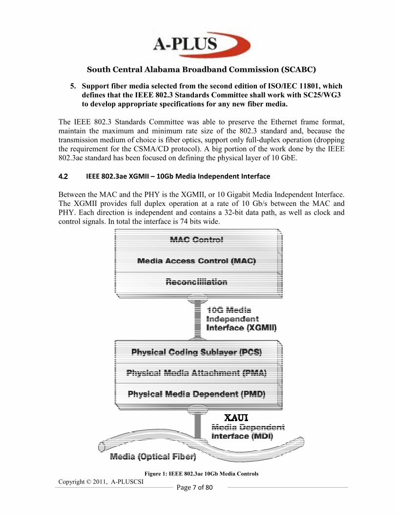
4.24.24.24.2 IEEE 802.3ae XGMII – 10Gb Media Independent Interface
Between the MAC and the PHY is the XGMII, or 10 Gigabit Media Independent Interface.
The XGMII provides full duplex operation at a rate of 10 Gb/s between the MAC and
PHY. Each direction is independent and contains a 32-bit data path, as well as clock and
control signals. In total the interface is 74 bits wide.
Figure 1: IEEE 802.3ae 10Gb Media Controls
South Central Alabama Broadband Commission (SCABC)
Copyright © 2011, A-PLUSCSI
Page 8 of 80
Ethernet is fundamentally a Layer 2 protocol. An Ethernet PHYsical layer device (PHY),
which corresponds to Layer 1 of the OSI model, connects the media (optical or copper) to
the MAC layer, which corresponds to OSI Layer 2.
The 802.3ae specification defines two PHY types, LAN and WAN.
4.34.34.34.3 IEEE 802.3ae PHY Families
Two new physical layer specifications are part of the 10 GbE standard framework: LAN
PHY and WAN PHY. In general the properties of the PHY are defined in the Physical
Coding Sublayer (PCS) which is responsible for the encoding and decoding functions.
LAN PHY - for native Ethernet applications. There are two types of LAN PHY:
• WWDM LAN PHY - uses a physical coding sublayer (PCS) based on four
channels or lanes of 8B/10B coded data. Each lane operates at 2.5 Gb/s with a
coded line rate of 3.125 Gb/s.
• Serial LAN PHY - initially it appeared attractive to reuse the 8B/10B code used
with Gigabit Ethernet, however it was soon realised that the resulting 12.5 Gbaud
would require costly technical issues to be solved and raise the development cost of
effective serial implementation. It was therefore decided to employ a more efficient
64B/66B code, which reduced the serial baud rate to 10.3125 GBaud.
WAN PHY - for connection to 10 Gb/s SONET/SDH - there is one type of WAN PHY:
• Serial WAN PHY - For this PHY an additional sub-layer known as the WAN
Interface Sub-layer (WIS) is required between the PCS and the serial PMA. The
position of this in the 10GBASE-W architecture is shown in Figure 1. The WIS
maps the output of the serial PCS into a frame, based on SONET/SDH practice and
vice versa, and processes the frame overhead including pointers and parity checks.
The line rate is 9.95328 Gb/s.
The WAN PHY has an extended feature set added onto the functions of a LAN PHY.
Ethernet architecture further divides the PHY (Layer 1) into a Physical Media Dependent
(PMD) and a Physical Coding Sublayer (PCS). The two types of PHYs are solely
distinguished by the PCS.
South Central Alabama Broadband Commission (SCABC)
Copyright © 2011, A-PLUSCSI
Page 9 of 80
Figure 2: IEEE 802.3ae Physical Layer Focus & Definition
The LAN PHY and WAN PHY differ in the type of framing and interface speed. Serial
LAN PHY (10GBASER) adopts Ethernet framing and the data rate is 10.3125 Gb/s (the
MAC runs at 10,000 Gb/s and by adding the coding redundancy of 64B/66B the effective
line rate becomes 10,000 * 66 / 64 = 10,3125 Gb/s.). On the other hand WAN PHY wraps
the 64B/66B encoded payload into a SONET concatenated STS-192c frame in order to
generate a data rate of 9.953 Gb/s.
So why do we need WAN PHY? The traditional optical transport infrastructure is based on
the SONET/SDH protocols which operate at a speed of 9.953 Gb/s. LAN PHY has a line
rate of 10.3125 Gb/s which does not match the speed of SONET/SDH, thus it cannot be
transported as it is over wide area networks based on SONET/SDH.
A mechanism to transport 10 GbE across wide area networks built around SONET/SDH
was deemed required. WAN PHY is the IEEE answer to adapt 10 GbE data rate to the
speed of SONET/SDH, the dominant technologies deployed in optical transport networks.
South Central Alabama Broadband Commission (SCABC)
Copyright © 2011, A-PLUSCSI
Page 10 of 80
The purpose of WAN-PHY is to render 10 GbE compatible with SONET STS-192c format
and data rate, as defined by ANSI, as well as the SDH VC-4-64c container specified by
ITU. WAN PHY is not strictly SONET compliant, but rather we can think of WAN PHY
as a SONET-friendly variant of 10 GbE. The optical specifications as well as the timing
and jitter requirements remain substantially different from the SONET/SDH protocols.
As a result of the standardization effort, various optical interface types have been defined
(or in IEEE jargon, various Physical Medium Dependent sublayers, a.k.a. PMDs) to
operate at various distances on both single mode and multimode fibers. In addition to these
PMDs the standard introduces two new families of physical layer specifications (a.k.a.
PHYs in the IEEE lingo) to support LAN as well as WAN applications.
Ethernet for subscriber access networks, also referred to as “Ethernet in the First Mile,” or
EFM, combines a minimal set of extensions to the IEEE 802.3 Media Access Control
(MAC) and MAC Control sublayers with a family of Physical Layers. These Physical
Layers include optical fiber and voice grade copper cable Physical Medium Dependent
sublayers (PMDs) for point-to-point (P2P) connections in subscriber access networks.
EFM also introduces the concept of Ethernet Passive Optical Networks (EPONs), in which
a point-to-multipoint (P2MP) network topology is implemented with passive optical
splitters, along with extensions to the MAC Control sublayer and Reconciliation Sublayer
as well as optical fiber PMDs to support this topology. In addition, a mechanism for
network Operations, Administration, and Maintenance (OAM) is included to facilitate
network operation and troubleshooting. 100BASE-LX10 extends the reach of 100BASE-X
to achieve 10 km over conventional single-mode two-fiber cabling. The relationships
between these EFM elements and the ISO/IEC Open System Interconnection (OSI)
reference model are shown in Figure 2.
Since 10GbE is a full-duplex only, it does need the Carrier-Sensing Multiple-Access with
collision detection (CSMA/CD) protocol that defines slower, half-duplex Ethernet
technologies, yet 10GbE remains true to the original Ethernet OSI Model.
4.44.44.44.4 IEEE 802.3ae XAUI – 10GbE Attachment Unit Interface
The XAUI (pronounced “Zowie”) is the 10GbE MDI. Remember the old AUI's that
ancient Ethernet (over large coax, or "frozen garden hose") drops with their BNC
connectors used?? Well, this is the same thing only faster. The XAUI is an interface
extender, and the interface, which it extends, is the XGMII. The XGMII is a 74 signal
wide interface (32-bit data paths for each of transmit and receive).
The XAUI is not mandatory, because the XGMII can be used to directly attach the
Ethernet MAC to its PHY! However, most applications want the extender for both
physical workability, and for adaptation to Fiber Connectors.
South Central Alabama Broadband Commission (SCABC)
Copyright © 2011, A-PLUSCSI
Page 11 of 80
The XAUI may be used in place of, or to extend, the XGMII. The XAUI is a low pin count,
self-clocked serial bus directly evolved from Gigabit Ethernet. The XAUI interface speed
is 2.5 times that used in Gigabit Ethernet. By arranging four serial lanes, the 4-bit XAUI
interface supports the ten-times data throughput required by 10 Gigabit Ethernet. The
XAUI employs the same robust 8B/10B transmission code of Gigabit Ethernet to provide a
high level of signal integrity through the copper media typical of chip-to-chip printed
circuit board traces. Additional benefits of XAUI technology include its inherently low
EMI (Electro- Magnetic Interference) due to it’s self-clocked nature
The XAUI is the actual physical interface for GbE, and has 70 pins. The XAUI is a full
duplex interface that uses four (4) self-clocked serial differential links in each direction to
achieve 10 Gb/s data throughput. Each serial link operates at 3.125 Gb/s to accommodate
both data and the overhead associated with 8B/10B coding. The self-clocked nature
eliminates skew concerns between clock and data, and extends the functional reach of the
XGMII by approximately another 50 cm.
Conversion between the XGMII and XAUI interfaces occurs at the XGXS (XAUI GbE
Extender Sublayer).
South Central Alabama Broadband Commission (SCABC)
Copyright © 2011, A-PLUSCSI
Page 12 of 80
4.54.54.54.5 IEEE 802.3ae PMD Sublayers
The proliferation of PMD sublayers promoted by the standard may sound confusing at first,
but each PMD has different technical characteristics in order to support different fiber
media and operating distances. The approach chosen by IEEE can be explained with the
intent to offer the cheapest optical technology possible for a particular application.
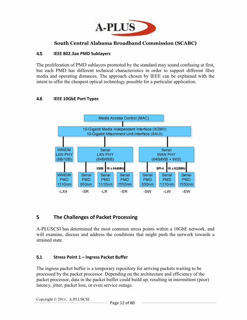
4.64.64.64.6 IEEE 10GbE Port Types
5 The Challenges of Packet Processing
A-PLUSCSI has determined the most common stress points within a 10GbE network, and
will examine, discuss and address the conditions that might push the network towards a
strained state.
5.15.15.15.1 Stress Point 1 – lngress Packet Buffer
The ingress packet buffer is a temporary repository for arriving packets waiting to be
processed by the packet processor. Depending on the architecture and efficiency of the
packet processor, data in the packet buffer could build up, resulting in intermittent (poor)
latency, jitter, packet loss, or even service outage.
South Central Alabama Broadband Commission (SCABC)
Copyright © 2011, A-PLUSCSI
Page 13 of 80
In most architectures, when packet buffers begin to fill beyond a preset threshold, the
packet processor initiates flow control to the upstream MAC device, requesting it to stop
passing packets. The MAC device then transmits a special packet requesting remote ports
to delay sending packets for a period of time. This special packet is called a pause frame.
This helps prevent buffer overflow, but it does not solve the packet loss problem
completely. If the packet flow continues and the flow control signal is not removed by the
packet processor before the MAC device’s buffer fills up, the MAC device will start
dropping packets.
Generally, the buffer in any part of the system can build up for two reasons:
� Local or downstream devices are exceeding their allocated processing budget; or
� There is contention for resources for instance, multiple ingress ports on a
switch/router contending for an egress port.
Buffer buildup can create a chain reaction, leading to unpredictable behavior in a switch or
router.
Another challenge in packet buffering for 10GE switches is dealing with back-to-back
small packets. For example, at 10 Gbps speeds, arriving 64-byte packets must be deposited
into buffer memory every 67 nanoseconds (ns), and departing packets must be retrieved
from buffer memory every 67ns. Thus, to process a stream of back-to-back 64-byte
packets, the packet buffer memory subsystem must support a write and a read every 67ns.
5.25.25.25.2 Stress Point 2 – Packet Classification
Packet classification is one of the most susceptible stress points. Classification maps
information from the packet header to information stored in local tables maintained by a
control plane processor (see "Stress Point 6: Control plane"). The packet processor parses
various fields in the packet header to construct search keys. These keys are then used to
address various tables. In most high-end architectures, Ternary Content Addressable
Memory (TCAM) devices or equivalent technologies are used to map these keys to
addresses, and are capable of holding millions of entries and performing key searches in a
matter of few internal clock cycles. However, complex applications or routing protocols
may require multiple key searches to drive a look-up result. Furthermore, separate
classification sequences may be required to determine what to do with a packet. For
example, the packet processor may perform an ACL look-up first to decide whether to
forward or deny a packet, and then do a route look-up to decide where to forward it. It
might also perform a flow control look-up to provide enhanced services.
The required degree of packet parsing and processing is one of the main criteria that
identifies the class of a switch/router. A simple Layer 2-3 switch only inspects the L2
header (i.e., MAC header, VLAN), and the L3 header (i.e., IPv4, IPv6), and, in some cases,
performs limited flow classification.
South Central Alabama Broadband Commission (SCABC)
Copyright © 2011, A-PLUSCSI
Page 14 of 80
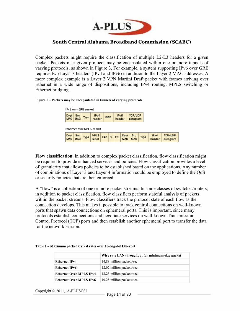
Complex packets might require the classification of multiple L2-L3 headers for a given
packet. Packets of a given protocol may be encapsulated within one or more tunnels of
varying protocols, as shown in Figure 3. For example, a system supporting IPv6 over GRE
requires two Layer 3 headers (IPv4 and IPv6) in addition to the Layer 2 MAC addresses. A
more complex example is a Layer 2 VPN Martini Draft packet with frames arriving over
Ethernet in a wide range of dispositions, including IPv4 routing, MPLS switching or
Ethernet bridging.
Figure 1 – Packets may be encapsulated in tunnels of varying protocols
Flow classification. In addition to complex packet classification, flow classification might
be required to provide enhanced services and policies. Flow classification provides a level
of granularity that allows policies to be established based on the applications. Any number
of combinations of Layer 3 and Layer 4 information could be employed to define the QoS
or security policies that are then enforced.
A “flow” is a collection of one or more packet streams. In some classes of switches/routers,
in addition to packet classification, flow classifiers perform stateful analysis of packets
within the packet streams. Flow classifiers track the protocol state of each flow as the
connection develops. This makes it possible to track control connections on well-known
ports that spawn data connections on ephemeral ports. This is important, since many
protocols establish connections and negotiate services on well-known Transmission
Control Protocol (TCP) ports and then establish another ephemeral port to transfer the data
for the network session.
Table 1 – Maximum packet arrival rates over 10-Gigabit Ethernet
Wire rate LAN throughput for minimum-size packet
Ethernet IPv4 14.88 million packets/sec
Ethernet IPv6 12.02 million packets/sec
Ethernet Over MPLS IPv4 12.25 million packets/sec
Ethernet Over MPLS IPv6 10.25 million packets/sec
South Central Alabama Broadband Commission (SCABC)
Copyright © 2011, A-PLUSCSI
Page 15 of 80
Look-ups and Performance. Classification table information is typically stored in a look-
up table, usually held in a large TCAM or equivalent technology. When processing
encapsulated packets or packets with multiple L2/L3 headers (i.e., IPv6 over IPv4, or
MPLS stacks with Ethernet header, IP header, and TCP) the classification process might
require multiple accesses to the look-up table for each packet.
Table 1 shows the worst-case performance packet arrival rate for small packets. Depending
on the packet arrival rate and number of required look-ups per packet, the packet processor
or the classification device could become a resource bottleneck. For example, a back-to-
back Ethernet packet with an IPv6 datagram requiring ACL and flow look-up might require
7–8 look-ups per packet. With 12 million packets arriving per second, this will require the
network to handle approximately 96 million look-ups/sec.
5.35.35.35.3 Stress Point 3 – Traffic Management
The traffic management function provides advanced queuing, congestion management, and
hierarchical scheduling of network traffic for large numbers of flows. It forwards traffic
according to a user-defined set of rules pertaining to priority levels, latency and bandwidth
guarantees, and varying congestion levels. It also provides the packet buffering required to
perform instructions with any queuing mechanisms used to manage traffic flow across the
switch fabric.
Communication from line card to switch fabric requires additional flow control
information, creating overhead and increased bandwidth. This additional bandwidth is
called speedup. See "Speed-up." on page 18.
The architecture of a switch/router can affect how the network behaves in times of heavy
demand. An important concern is how packets are queued as they enter the switching
fabric, that is, how traffic prioritization is handled and how different traffic flows are
merged through the fabric.
Some products forward all high-priority packets before any lower-priority packets; this is
called strict priority queuing. Other products use mechanisms such as Weighted Fair
Queuing (WFQ) to statistically multiplex packets into the fabric. On the ingress line card,
WFQ allows packets from lower priority queues to be interleaved with higher priority
traffic into the switch fabric. This prevents the higher priority traffic from completely
blocking the lower priority traffic, since the queues are guaranteed access to the switch
fabric for a predefined proportion of the time.
Packet discarding is also part of traffic management. During times of congestion, the traffic
manager may need to make discard decisions based on the availability of queue space,
priority, or destination port, using a packet discard algorithm like Random Early Detection
(RED) or Weighted RED (WRED) for IP traffic.
South Central Alabama Broadband Commission (SCABC)
Copyright © 2011, A-PLUSCSI
Page 16 of 80
Some routers and switches are fundamentally limited by the small number of queues they
have for QoS. Small numbers of queues are common for class-based queuing, which limits
prioritization and fairness. Class-based queuing typically prioritizes traffic based on the
Layer 2 header (virtual LAN and source or destination MAC address, for example), rather
than on higher level information such as application or protocol type.
Systems with large numbers of queues facilitate more granular prioritization and greater
fairness. Queues established on a per-flow basis provide the possibility for each user
session to get its own queue. However, a large number of CoS and QoS policies requires
large amounts of memory and hierarchical schedulers capable of handling hundreds of
thousands of flows.
5.45.45.45.4 Stress Point 4 – Control Plane
The control plane processor handles the routing and switching control plane, as well as
many system management operations, such as user configuration, background diagnostics,
statistics and alarm collection and reporting, network management, etc. This document
focuses only on how the control and data plane interact for the purpose of packet
processing.
The control plane processor runs the switch/router’s operating system and is responsible for
the operation of network routing protocols (OSPF, BGP, IS-IS, IGRP), network
management (SNMP), console port, diagnostics, etc. In a distributed architecture, where
each line card has its own control plane processor, a master control plane processor
typically generates, synchronizes, and distributes routing tables and other information
among line cards for local forwarding decisions.
The control plane path interconnects the management processor(s) with various data plane
blocks, to initialize, configure, perform diagnostics, and most importantly, to set up or
update routing tables, Layer 2 tables, policies, and QoS/CoS tables.
The control processor can read/write to any location in the forwarding table, context
memory, and other memories to support route removal and addition, table flushing in route
flaps, and policy for a given flow.
The look-up and table management operation is asynchronous. The route table may be
updated by the control plane processor while the packet processor is performing a look-up.
During ordinary system operation and moderately stressed conditions, the control plane
would not be called upon to modify more than a few thousand routes per second in
response to a routing protocol update, while the system is at the same time forwarding data
plane packets. However, during error conditions, or a topology alteration known as route
flapping or route convergence, hundreds of thousands of routes may be modified each
second while packets are still arriving on each interface at up to line rate.
South Central Alabama Broadband Commission (SCABC)
Copyright © 2011, A-PLUSCSI
Page 17 of 80
Therefore, determining how fast a switch/router can update its routing table requires a
testing platform that can create/modify hundreds of thousands of route updates per second
while performing normal data plane operation, that is, forwarding packets at line rate.
5.55.55.55.5 Stress Point 5 – Multicast Replication and Queues
The biggest challenge in handling multicast packets is packet replication. Packet replication
is generally accomplished in two stages. The first stage handles the branch replications
from one ingress line card to multiple egress line cards. The second stage handles the leaf
replications, and is typically accomplished on the egress line card. Depending on the switch
architecture, the packet replication function could cause resource starvation in memory and
CPU processing, as well as contention with unicast packets, as it accesses the data plane to
forward the replicated packets.
New generation switches take advantage of the natural multicast properties of a crossbar
switch and perform cell replication within the fabric by closing multiple cross points
simultaneously. This method relieves the ingress line card from performing packet
replication. However, the second-stage replication on the egress line card can still cause
resource starvation and congestion.
5.65.65.65.6 Stress Point 6 – Ethernet Switch Backplane Interconnect
Although most switch architectures for modern systems are non-blocking, three types of
blocking can limit performance when multiple ingress ports are contending for an egress
port: Head-of-Line (HOL) blocking, input blocking, and output blocking. HOL blocking
can waste nearly half a crossbar switch's bandwidth if the cells waiting at each input are
stored in a single First-In, First-Out (FIFO) queue. Modern switch architectures employ
Virtual Output Queuing (VOQ). VOQ, in conjunction with a scheduling algorithm,
eliminates most blocking issues. These scheduling algorithms require the traffic manager
device and the switch fabric to exchange information, including requests for permission to
transmit, granting of permissions to transmit, and other information.
Speed-up. The additional bandwidth required to support VOQ and related scheduling
algorithms is called speed-up. A 10GE line card that supports 15 Gbps to the switch fabric
offers 50 percent speedup. Speed-up is a common way to reduce input and output blocking
by running the Ethernet switch faster than the external line rate. For example, if the
Ethernet switch runs twice as fast as the external line, the traffic manager can transfer two
cells from each input port, and two cells to each output port during each cell time.
The advantage of speed-up is obvious — it offers more predictable delay and jitter across
the switch ports by delivering more cells per cell time, and thus reducing the delay of each
cell through the switch. In fact, sufficient speed-up can guarantee that every cell is
immediately transferred to the output port, where its departure time can be precisely
scheduled.
South Central Alabama Broadband Commission (SCABC)
Copyright © 2011, A-PLUSCSI
Page 18 of 80
6 Conformance vs. Interoperability
An understanding of the concepts of conformance and interoperability is of paramount
importance when deciding which technologies should be deployed in the network. Not only
are the definitions of these concepts important, but also an understanding of the similarities
and differences between conformance and interoperability and how they relate to the
various pitfalls associated with these concepts. For example, it is possible that two devices
that are conformant to the standard will not necessarily be interoperable, and two devices
that are interoperable are not necessarily conformant. Additionally, it is possible that while
one device may interoperate with another device under a certain set of conditions, it may
not be interoperable under all conditions, or with all devices. Only exhaustive testing and
documentation can help to ensure that devices are both conformant to the standard, and
interoperable with the vast majority of available products.
6.16.16.16.1 Definition of Conformance
A device is said to be conformant, or compliant, to a standard if it has properly
implemented all of the mandatory portions of that standard. All mandatory portions of
IEEE 802.3 are set apart from the rest of the text by a shall statement. All statements that
say something shall or shall not happen are mandatory, and are necessary for a device to be
considered conformant. Additional statements within IEEE 802.3 include recommendations
(should, should not) and options (may, may not). State diagrams are often included along
with the supporting text in order to clearly and concisely describe the behavior of certain
protocols or functions. Adherence to the mandatory state diagrams and portions of the text
needs to be verified for every component and device before a statement of conformance
may be issued.
IEEE 802.3 includes at the end of every chapter, or clause, a Protocol Implementation
Conformance Statement (PICS). The PICS section allows the supplier to fill out a form
indicating which options and mandatory portions of the standard have actually been
implemented for a particular device or component. The supplier of any component or
system that is said to conform to a particular clause or set of clauses must fill out the PICS
associated with each clause that is relevant for that device. Each Physical Medium
Dependent (PMD) sublayer, Physical Coding Sublayer (PCS), and Reconciliation Sublayer
(RS) has a PICS section that must be filled out. The PICS sections include a unique item
for all mandatory features of the specification. Each PICS item should have an associated
shall statement, and each shall statement should have an associated PICS item.
It should be stressed that even though these PICS forms do exist and are completed by the
supplier of a device, it does not guarantee that the device is conformant to every item that
has been checked off. In many instances, it is desirable for an independent third party to
verify the legitimacy of such a claim by performing a set of conformance tests, which are
South Central Alabama Broadband Commission (SCABC)
Copyright © 2011, A-PLUSCSI
Page 19 of 80
usually based off of the PICS, on the device in question. Additionally, in any given full
system, there are likely to be components from a number of different suppliers, each of
which needs to be compliant to the respective part of the standard. Whether it is an optics
module, SERDES chip, MAC chip, or another component, testing must be done to verify
that the individual components conform to the standard. When all of the components are
put together into a full system, it is imperative that all PICS items are re-evaluated to
ensure that conformance has not been compromised due to board layout, power, thermal, or
other problems that may arise when the components are incorporated into the system.
Testing and verification is necessary at the component and system level to provide proof
that a device is truly conformant.
6.26.26.26.2 Definition of Interoperability
Two or more devices are said to be interoperable if, under a given set of conditions, the
devices are able to successfully establish, sustain, and if necessary, tear down a link while
maintaining a certain level of performance. This definition is somewhat more problematic
and complicated than the definition of conformance. So in order to claim the
interoperability of a set of devices, it is necessary to first establish an accepted set of
criteria that will be used to judge these claims. The set of criteria may include: definitions
of the communications channel over which interoperability testing will take place,
specifications of the type or amount of data that will be transmitted and received over the
channel, events that trigger when certain defined states or conditions have been reached or
completed, and the level of performance over which the above criteria must be maintained.
A common set of guidelines must be developed and accepted by the industry as a whole so
that claims of interoperability from one vendor will have been made under the same
circumstances as another competing vendor, and thus allowing the end-user to fairly
evaluate one product over another.
While a standard may not always explicitly define these criteria, the conditions over which
interoperability must exist can and should be derived from the standard. In many instances,
the standard will define the worst-case conditions over which a device must be able to
properly operate. This is usually written in such a manner as to define a particular Bit
Error Ratio (BER) that must be supported over these conditions. However, it should be
noted that the worst-case conditions do not always exist on a given link between two
devices, nor are they always defined as realistic conditions. Additionally, the statement that
two devices work under worst-case conditions does not necessarily imply that the two
devices will work under all conditions, including those conditions that may be less stressful
than the worst-case conditions.
Using IEEE 802.3 as an example, it is typically an external organization that defines an
initial set of interoperability criteria. Recently, during the development of IEEE 802.3ae, 10
Gigabit Ethernet, a joint effort between the UNH – IOL and 10 Gigabit Ethernet Alliance
(10GEA) created documentation specifying the means and metrics by which 10 Gigabit
Attachment Unit Interface (XAUI) devices should be tested. The document specifies the
South Central Alabama Broadband Commission (SCABC)
Copyright © 2011, A-PLUSCSI
Page 20 of 80
channel over which testing is to be performed, the data that will be sent over the channel,
the duration of the test, and the pass/fail criteria of the test. This document was used as the
basis for all XAUI interoperability testing, having been defined and agreed upon by a large
group of participating companies and individuals, and thus supplying the industry with a
common set of criteria from which to judge interoperability.
6.36.36.36.3 Interoperability and Conformance
As previously stated, having either conformance or interoperability does not necessarily
imply that the other also exists. A device that claims to be conformant should, by
definition, have implemented all of the mandatory portions of the standard. Although the
standard may define the interfaces of a layer and its requirements, it does not define nor
make an attempt to define how such interfaces and requirements are implemented by a
designer. Various implementations are allowed to exist to, among other reasons, promote
competition and in many cases it is necessary for designs and implementations to be
available from multiple sources before a technology can be successful. With the ability
and desire to have multiple implementations comes the potential to have implementations
that although conformant, are not interoperable.
The ability to implement multiple options is another inhibitor of interoperability. As the
number of optional features increases, so, too, does the risk of having interoperability
problems. There are some options that, whether implemented or not, will have no impact
on interoperability. For example, IEEE 802.3 Annex 31B within IEEE Std. 802.3 – 2002
defines a frame-based flow control protocol. All frames transmitted in this protocol must
not exceed a size of 64-bytes. When a device is receiving one of these frames however, it
may optionally accept protocol frames that are larger than 64-bytes in length. The
implementation of such an option will not impede on the interoperability between two
conformant devices that only transmit 64-byte frames. If one device does accept the larger
frames and the other device does not, there will be no problems observed due to this
difference.
Other options may exist that do have a large impact on the interoperability of two devices.
It is possible for two conformant devices that have implemented options differently to have
interoperability problems. A recent draft of IEEE P802.3ah specifies an optional
mechanism for Forward Error Correction (FEC) that can be implemented on an EPON.
The draft implies that the FEC may be used by the both the Optical Line Terminal (OLT)
and Optical Network Unit (ONU), one of the two devices, or neither of them. These four
different options would provide for four very different examples of interoperability. In the
first example, when both the OLT and ONU have implemented FEC, the results will be the
best, and the two devices will interoperate over the greatest length of fiber, or similarly,
with a higher split ratio. In the other cases, when one or fewer of the two devices has
implemented FEC, the ability to interoperate over the same conditions as previously stated
will have been altered. It is likely that a shorter length of fiber or a fewer number of splits
South Central Alabama Broadband Commission (SCABC)
Copyright © 2011, A-PLUSCSI
Page 21 of 80
would be necessary in order to operate at the same BER as in the first case. Obviously, this
option has the potential to significantly impact the link between the OLT and ONU, and
therefore great care must be taken when deploying a network of this type such that the
number of available options is either reduced or clearly presented to the end-users.
It is also possible to have two devices, which are able to interoperate but are not
conformant to the standard. There are multiple scenarios in which this statement can be
made true. First, it is possible for two different devices to have implemented a very
important mandatory feature wrongly, but in the in a similar way. For example, if two
devices both reversed the bit ordering of their frames, then they would be obviously non-
conformant and highly unlikely to interoperate with other conformant devices. However,
when connected to each other, the two devices would interoperate as if they both were
conformant to the same standard, and it is possible that the users may not even recognize
the non-conformant behavior. An additional scenario could be that the two devices were
able to interoperate but were non-conformant with features that were unrelated to
interoperability. For example, in IEEE 802.3 Clause 57 the Operations Administration and
Maintenance (OAM) protocol, requires that at most ten OAM frames be sent each second
in order to keep the OAM link alive and provide the periodic feedback of information from
one device to another. If one device, or both of them, were to violate the maximum count
of ten OAM frames per second and increased that value to eleven or twelve, then although
strictly non-conformant, the two devices would still interoperate perfectly fine. There is no
part of the OAM protocol itself that would break or cease to function if additional frames
were received each second. This introduces the concept that not all mandatory portions of
a standard need to be treated equally.
6.46.46.46.4 Necessity of Conformance
Throughout the development of a complete system, there are hundreds if not thousands of
compliance checks that need to be validated. As shown above, it is clear that the proper
implementation of some of these features is more important than others. That being said, it
is often difficult to determine what features need to be implemented as specified in the
standard so that interoperability problems will not arise. The answers to these questions
can only be found through exhaustive conformance and interoperability testing of a wide
range of products and implementations. When two devices fail to interoperate with each
other, one of the first steps in debugging the problem is to evaluate the results of the
conformance testing. Over time, the database of information gained from collecting
conformance results of a variety of products will allow testers and users to not only
determine which conformance issues will affect interoperability, but to also predict certain
interoperability problems based on conformance results, and to predict conformance
problems based on interoperability results.
For example, in the early days of Gigabit Ethernet, observations were made between
certain devices that roughly half of all frames transmitted from one device to another across
the same optical link were dropped. Both devices were observed to interoperate perfectly
South Central Alabama Broadband Commission (SCABC)
Copyright © 2011, A-PLUSCSI
Page 22 of 80
with other devices, but not with each other. The cause of the problem was discovered
through the conformance testing. The IEEE 802.3 Clause 36 PCS allowed for frames to be
transmitted with either six or seven bytes of preamble, which are the beginning bytes of the
frame that have traditionally been used for synchronization of the receiving clock. Certain
devices implementing this PCS, however, were not capable of receiving frames with six
bytes of preamble and would discard those frames. On a link that sent randomly sized
traffic, approximately half of the transmitted frames could be sent with six bytes of
preamble, thus accounting for the large frame loss. The conformance testing provided the
cause of the lost frames, which was an observable interoperability problem. After this
discovery, it was observed that in most instances that the frame loss occurred, the
conformance issue also existed, and in cases that the conformance issue existed, the
interoperability problem was observed.
For those features that are clearly defined in the standard, conformance testing is fairly
straightforward and interoperability issues that arise from those features can usually be
explained in a timely fashion. An even greater problem lies within those features that are
not dealt with by the standard. For various political and technical reasons, a single
standards body may not define some features of a technology. In many cases, it may be
considered out of the scope of what the standards body is allowed to do. When this occurs,
it is important that all interested parties come together to define implementation agreements
that can be tested against and followed to maximize the likelihood of interoperability. One
such example, the development of pluggable optics modules, can be shown through a
number of Multi-Source Agreements (MSA).
It has been shown that conformance and interoperability, while not interchangeable
concepts, are nonetheless related to each other in an often strange and difficult to define
manner. It is clear, however, that one of the keys to identifying and solving interoperability
problems is defining and implementing a comprehensive set of both conformance and
interoperability tests. The development and acceptance of these test procedures and the
observations of the test results can be powerful tools to aid in the documentation, analysis,
and solution of various interoperability problems.
It can be expected, that as a technology matures, the number of interoperability and
conformance problems should decrease. Early implementations are often replaced by more
rugged and stable implementations, and products that are unable to interoperate with others
or conform to the defined standard are usually weeded out as more and more
implementations become available. An environment that has a large number of vendors
competing to make similar products is more likely to lend itself to an interoperable and
conformant technology than an environment with only a small number of players.
Additionally, a strong push from the community to require vendors to demonstrate
interoperability and conformance helps to foster this type of environment.
It is important to note that even though the number of interoperability problems virtually
disappeared by the end of 1999, the number of device pairs that were tested since then
South Central Alabama Broadband Commission (SCABC)
Copyright © 2011, A-PLUSCSI
Page 23 of 80
shows there was a strong desire from the Gigabit Ethernet community to continue to
demonstrate interoperability. This is significant, because companies are constantly
developing new devices, and upgrading hardware, firmware, and software on their existing
equipment. The need for proven interoperability does not diminish as time goes on. When
a new product is introduced to an environment where interoperability and conformance are
expected, it is necessary for the supplier to demonstrate its interoperability and
conformance before it will be purchased and placed into the existing network architecture.
7 Developing the Right Test Methodology
Understanding the stress points within a network allows the development of a test
methodology that can focus on testing of these areas. Our test methodology will address
multiple layers, and will include test parameters for:
� Wire speed unicast data throughput and latency for Layer 2/3 traffic.
� The ability to filter packets at wire-speed based on MAC addresses, IP addresses,
TCP or UDP ports, or a combination of these (N-tuple).
� The ability to perform prioritization based on QoS markings.
� The ability to police traffic based on user-defined rate limits.
� The ability to handle Head-of-Line blocking (HOL).
� Wire speed multicast performance.
Our test methodology is broken out into component and system-level testing. In the real
world, local switching occurs on the module; this is the best-case scenario for switch
performance, because there is no contention for the switching fabric. The worst-case
scenario is when all traffic entering the switch must traverse the switching fabric,
contending for backplane capacity and causing over-subscription.
1. Layer 2 bidirectional throughput and latency test. This test determines the
Device Under Test’s (DUT’s) maximum Layer 2 forwarding rate without traffic
loss as well as average latency for different packet sizes. This test is performed full
duplex with traffic transmitting in both directions. The DUT must perform packet
parsing and Layer 2 address look-ups on the ingress port and then modify the
header before forwarding the packet on the egress port.
2. Layer 2 throughput, QoS, and latency test. This test determines the DUT's
maximum Layer 2 forwarding rate with packet loss and latency for different packet
sizes. The DUT must perform a Layer 2 address lookup, check the 802.1p priority
bit value on the ingress port, send it to the designated queue, and then modify the
header before forwarding the packet on the egress port.
3. Layer 3 (IPv4) performance test with ACL and latency. This test determines the
DUT's maximum IPv4 Layer 3 forwarding rate with packet loss and latency for
different packet sizes. The DUT must perform packet parsing and route look-ups
for both Layer 2 and Layer 3 packets on the ingress port and then modify the header
South Central Alabama Broadband Commission (SCABC)
Copyright © 2011, A-PLUSCSI
Page 24 of 80
before forwarding the packet on the egress port. The ACL test involves blocking or
allowing traffic through, based on user-defined classifiers such as IP addresses or
Layer 4 port numbers. Ixia routing emulation software is used to populate the
DUT's routing table,. For example, OSPF emulation is used to generate OSPF LSAs
to construct topological databases.
4. Layer 3 (IPv4) performance test with ACL, QoS, and latency. In addition to test
3 above, QoS values in each header will force the classification of the traffic based
on IP Type of Service (TOS) field settings. On the ingress side, this QoS policy
could also be used for assigning a packet to a specific queue, packet metering, and
policing; on the egress side, it could be used for packet shaping.
5. Layer 3 (IPv6) performance test with ACL and latency. This test methodology
is the same as the previous Layer 3 IPv4 with ACL performance test, except that it
runs IPv6 traffic with a minimum-size packet of 84 bytes instead of 64 bytes. Due
to the larger IPv6 header, the classification and table look-up functions will require
more bandwidth and processing.
6. Layer 3 (IPv6) performance test with ACL, QoS, and latency. In addition to test
5 above, QoS values in each header force the classification of the traffic, based on
the TOS field setting. On the ingress side, this QoS policy could also be used for
assigning a packet to a specific queue, packet metering, and policing; on the egress
side, it could be used for packet shaping.
7. Multicast test. This test uses a multicast protocol such as IGMP (IPv4) or MLD
(IPv6) to set up multicast sessions between a multicast transmitter and groups of
receivers. A multicast protocol emulation can be used to simulate one or more hosts
while the DUTs function as IGMP/MLD routers. The simulation calls for groups of
simulated hosts to respond to IGMP/MLD router-generated queries and to generate
reports automatically at regular intervals. A number of IGMP groups are randomly
shared across a group of hosts.
A-PLUSCSI anticipants performing test procedures based on the following tables which
represents our test methodology, addresses its expected impact on the different stress points
mentioned earlier in this document, and baseline reports based on the network's design
criteria.
As an example, in Table 1, Row 1 (Component-level, Full duplex Layer 2 performance and
latency, with prioritization): all stress points show low or no stress, except for Stress Point
3, which points to the line card function that services the different priority queues.
However, in Row 6 (Layer 3 IPv6 performance, ACL and QoS), Stress Points 1 and 2 show
that a high level of strain is to be expected. This is because we know that the switch is
designed to handle wire-speed Layer 3 IPv4 packets, but not IPv6. This may mean that
packet classification for IPv6 addresses may take more clock cycles, which may require
more buffering on the ingress.
South Central Alabama Broadband Commission (SCABC)
Copyright © 2011, A-PLUSCSI
Page 25 of 80
Table 1 – Component-level test methodology and stress points
With system-level testing, additional strain will occur with the traffic management and
switching functions (Stress Points 3 and 4) because of a high level of traffic contending for
backplane switching capacity. For example, row 4 (Mesh Layer 3 IPv6, with route
flapping), shows additional strain not only in Stress Points 3 and 4, but also in Stress Point
6 (the control processor). Because of route flapping, it needs to modify the routing table as
packets continue to arrive on each interface.
South Central Alabama Broadband Commission (SCABC)
Copyright © 2011, A-PLUSCSI
Page 26 of 80
Table 2 – System-level test methodology and stress points
8 The A-PLUS Test Methodologies
8.18.18.18.1 The Basis for Layer 2 and Layer 3 Testing
The Layer 2 Ethernet switch is one of the most common networking devices. Layer 2
switching is associated with the Data Link Layer (Layer 2) of the standard of network
programming, the Open Systems Interconnection (OSI) model. Layer 2 Ethernet switches
forward traffic, also called network frames, across various network segments. Forwarding
is based on information in the frame’s Ethernet header.
Layer 2 switches are simple compared with sophisticated switches and routers operating at
Layer 3 and higher. But even Layer 3+ switches usually have a “Layer 2 mode.” In fact, it
is often preferable to assure that switches and networks operate at lower layers before
testing at upper layers of the OSI stack.
By testing at Layer 2 before Layer 3, network equipment manufacturers increase their
success rate in development testing and quality assurance while using in-house tools.
However, NEMs also need third-party tools for unbiased, hard results of switch
performance. Once assured of an acceptable level of performance and scalability, NEMs
market their equipment to service providers and enterprises.
To justify equipment choices and offer the highest quality services, service providers and
enterprises should test according to accepted standards. After the equipment is deployed in
live networks, existing equipment can be retested in the lab using the same RFC-based test
South Central Alabama Broadband Commission (SCABC)
Copyright © 2011, A-PLUSCSI
Page 27 of 80
tools. Regression testing allows users to compare baseline results with results obtained
after the equipment or switch is updated with the latest firmware.
Layer 3 switches, also called routers, determine the next network point to which a packet
should be forwarded toward its destination. The router is connected to at least two
networks and decides which way to send each information packet based on its current
understanding of the networks.
Since routing is associated with the Network Layer (Layer 3) in the standard model of
network programming, the Open Systems Interconnection (OSI) model. A router may
create or maintain a table of available routes and their conditions and use this information
along with distance and cost algorithms to determine the best route for a packet. Typically,
a packet may travel through many network points with routers before arriving at its
destination.
8.28.28.28.2 Assuredness and Interoperability Utilizing Industry Standards
NEMs, service providers and enterprises should quantify the performance of the Layer 2
switch by following industry standards. RFC 2889 (Benchmarking Methodology for LAN
Switching Devices) is for local area switch testing. With its companion, RFC 2285
(Benchmarking Terminology for LAN Switching Devices), the RFCs together define
reliable, repeatable methods for evaluating Layer 2 switch performance in 10/100/1000
Mbps and 10Gig Ethernet.
The tester must introduce simulated network traffic to the Layer 2 switch and take
measurements on ports that receive traffic. Port patterns such as full mesh and partial mesh
(backbone) are specified, along with different frame sizes and traffic loads. The best test
tools easily create these “traffic prescriptions” and provide intuitive, meaningful results for
accurate and timely reporting.
Layer 3 switch manufacturers are not always sure how to test according to the well-
established methodologies. By understanding the techniques to test, network equipment
manufacturers increase their success rate with in-house tools for development testing and
quality assurance. They also need third-party tools for unbiased, hard results of switch
performance. Once assured of an acceptable level of performance and scalability,
manufacturers make their equipment available to their customers: service providers and
business customers, also referred to as enterprises.
To justify their equipment choices and have the best network services possible, service
providers and enterprises need to test per accepted standards before purchasing decisions
are made. After deployment into live networks, existing equipment can be re-tested in lab
environments using the same RFC-based test tools. By performing regression testing, users
can compare baseline test results with results after equipment is updated with new versions
of switch firmware.
South Central Alabama Broadband Commission (SCABC)
Copyright © 2011, A-PLUSCSI
Page 28 of 80
One of the first steps to quantify the performance of the Layer 3 switch is to follow
industry standards. RFC 2544 (Benchmarking Methodology for Network Interconnect
Devices) is for Layer 3 switch testing. With its companion, RFC 1242 (Benchmarking
Terminology for Network Interconnect Devices), the RFCs together define reliable,
repeatable methods for evaluation of Layer 3 switch performance using 10/100/1000 Mbps
and 10 Gig Ethernet.
Both RFC 2544 and this document refer to terms defined in RFC 1242, Benchmarking
Terminology for Network Interconnection Devices. Please refer directly to these
documents as needed.
9 Layer 2 Testing with RFC 2889
9.19.19.19.1 Fully Meshed Throughput, Frame Loss and Forwarding Rates
Objective
To determine the throughput, frame loss and forwarding rates of the DUT/SUT’s offered
fully meshed traffic as defined in RFC 2285.
Overview
This test will determine if the L2 switch can handle a full mesh of traffic (from all-ports to
all-ports) at various traffic loads. Fully meshed traffic stresses the switch fabric, fully
exercises the forwarding tables and reveals weaknesses in resource allocation mechanisms.
This test is more stressful and exacting than a simple forwarding rate test, which does not
penalize a switch that drops an occasional packet at all offered loads. It measures the
DUT/SUT’s forwarding rate and throughput on each of the recommended RFC 2889
frames sizes.
The forwarding rate test will determine the maximum number of frames per second the
DUT/SUT can forward, using various loads.
The throughput test will determine the maximum load at which the DUT/SUT will forward
traffic without frame loss.
Test Steps
1. Each test port will emulate a single L2 MAC address.
2. From all test ports, send L2 Learning frames to the DUT, and verify them. Ensure the
DUT will not “time out” addresses before the end of each test iteration.
3. Traffic will then be sent from every test port in a full mesh, round-robin fashion through
the DUT/SUT to every other test port. Traffic pattern shown below:
South Central Alabama Broadband Commission (SCABC)
Copyright © 2011, A-PLUSCSI
Page 29 of 80
Source Port Destination Ports (order of transmission)
Port #1 2 3 4 5 6 7 8 2 3 4 …
Port #2 3 4 5 6 7 8 1 3 4 5 …
Port #3 4 5 6 7 8 1 2 4 5 6 …
Port #4 5 6 7 8 1 2 3 5 6 7 ...
Port #5 6 7 8 1 2 3 4 6 7 8 ...
Port #6 7 8 1 2 3 4 5 7 8 1 ...
Port #7 8 1 2 3 4 5 6 8 1 2 ...
Port #8 1 2 3 4 5 6 7 1 2 3 ...
4. Run forwarding rate test:
a. Using 64-byte test packets, a relatively low traffic load, and a 30-second test
duration, send packets as described in Step 3.
b. Observe the number of test frames per second the device successfully forwards.
c. Increase the load and rerun the test.
d. Repeat steps b and c until the maximum configured load is completed.
e. Report the maximum number of test frames per second that the device is
observed to successfully forward to the correct destination interface at each specified load.
5. Run throughput test:
a. Using 64-byte packets, a starting traffic load and a 30-second test duration, send
packets as described in Step 3. Determine if all packets are received.
b. Using a binary search algorithm, increase traffic load if no frame loss, and
decrease traffic load if frame loss occurs.
c. Continue binary search until maximum traffic load is achieved without frame
loss.
d. Report the maximum load (throughput) the device successfully forwards without
frame loss.
6. Repeat steps 1 to 5 for each remaining recommended frame size: 128, 256, 512, 1024,
1280 and 1518.
Test Parameters
• Frame sizes (including CRC): Recommended are 64, 128, 256, 512, 1024, 1280,
1518.
• Burst size between 1–930 frames (1 = constant load).
• Full or half duplex (10M/100M).
• Load per port in percentage (%).
• Each trial (or iteration) is 30 seconds (adjustable from 1–300).
Test Output
• Forwarding rate (maximum frames per second) for each frame size and for each
load.
• Throughput (maximum load with no frame loss) for each frame size.
• Flood count.
South Central Alabama Broadband Commission (SCABC)
Copyright © 2011, A-PLUSCSI
Page 30 of 80
Test Variables (Some variables are not RFC 2889 compliant)
• Longer trial/iteration duration.
• Tagged frames (802.1p&Q).
• Use different frame sizes from 64 to 1518 bytes.
• Use multiple frame sizes in the same test/iteration to simulate realistic traffic.
• Define Pass/Fail criteria, such as allowing small amounts of acceptable frame loss.
• IP/UDP header (TOS/TTL/Port#).
Sample Results
Starting Full Mesh Forwarding Rate Test
Frame Length = 64
Offered Load = 15,237,939 bps (20.00% util)
Forwarding Rate = 416,656 frames/sec (20.00% util)
Offered Load = 30,475,878 bps (40.00% util)
Forwarding Rate = 833,324 frames/sec (40.00% util)
Offered Load = 76,190,084 bps (100.00% util)
Forwarding Rate = 2,083,322 frames/sec (100.00% util)
Maximum Forwarding Rate (MFR) = 22,083,322 (frames/sec)
Forwarding Rate at Maximum Offered Load (FR-MOL) = 22,083,322 (frames/sec) at
MOL of 76,190,084 (bps) 100.00 (% util)
Starting Full Mesh Throughput Test
(Start = 100.0 Min = 0.0 Max = 100.0 Resolution = 0.5)
Frame Length = 64
Throughput test parameters: Start = 100.0 Min = 0.0 Max = 100.0 Res = 0.5
Offered load = 76,190,084 bps (100.000% util) ILoad = 100.000% util
Frame Loss Rate = 0.000002 (1 frame)
Offered load = 38,094,848 bps (50.000% util) ILoad = 50.000% util
Frame Loss Rate = 0.000003 (1 frame)
Offered load = 24,999,936 bps (32.813% util) ILoad = 32.813% util
Frame Loss Rate = 0.000000 (0 frames)
Offered load = 25,297,305 bps (33.203% util) ILoad = 33.203% util
Frame Loss Rate = 0.000005 (1 frame)
Binary search complete: Throughput is 224,999,936 bps (32.813% util)
9.29.29.29.2 Partially Meshed: One-to-Many/Many-to-One
South Central Alabama Broadband Commission (SCABC)
Copyright © 2011, A-PLUSCSI
Page 31 of 80
Objective
To determine the throughput when transmitting from one-to-many ports or from many-to-
one port. To measure the capability to switch frames without frame loss and determine the
ability to utilize a port when switching traffic from multiple ports.
Overview
This test will determine the forwarding rate of the L2 switch when traffic is sent from one-
to-many ports, or from many-to-one. The port patterns provide a unique challenge to each
of the three main logic sections of the switch: the ingress data path interface; the switch
fabric that connects the ingress ports to egress ports; and, the egress data path interface.
The traffic patterns used are one-way, reverse or bidirectional. The traffic load will be
stepped up on each iteration to determine the maximum forwarding rate of the DUT.
Caution should be used in the many-to-one test to avoid oversubscribing the “one” port.
The test will be run for each of the RFC 2889 recommended frame sizes.
Test Steps
1. Each test port will emulate a single L2 MAC address.
2. From all test ports, send L2 learning frames to the DUT and verify them. Ensure the
DUT will not “time out” addresses before the end of each test iteration.
3. Determine test type:
a. One-to-many – One port to many ports.
b. Many-to-one – Many ports to one-port.
4. Determine direction of traffic flow:
a. One-way – Unidirectional traffic flow.
b. Reverse – Opposite direction of one-way.
c. Bi-directionally – Both directions simultaneously.
5. The test port(s) will send traffic through the DUT/SUT to the other test port(s).
6. Run forwarding rate test:
a. Using 64-byte test packets, a relatively low traffic load and a 30-second test
duration, send packets as determined by steps 3, 4 and 5.
b. Observe the number of test frames per second the device successfully forwards.
c. Increase the load and rerun the test.
d. Repeat steps b and c until the maximum configured load has been completed.
e. Report the maximum number of test frames per second the device successfully
forwards to the correct destination interface at each specified load.
7. Repeat steps 1 to 6 for each remaining recommended frame size: 128, 256, 512, 1024,
1280 and 1518.
Test Parameters
• Frame sizes (including CRC): Recommended are 64, 128, 256, 512, 1024, 1280,
1518.
• Test type – One port to many ports, or many ports to one port.
• Traffic direction – One direction, reverse direction or both directions.
South Central Alabama Broadband Commission (SCABC)
Copyright © 2011, A-PLUSCSI
Page 32 of 80
• Burst size between 1–930 frames (1 = constant load).
• Full or half duplex (10M/100M).
• Load per port in percentage (%).
• Each trial (or iteration) is 30 seconds (adjustable from 1–300).
Test Output
• Forwarding rate (maximum frames per second) for each frame size and for each
load.
• Flood count.
Test Variables (Some variables are not RFC 2889 compliant)
• Longer trial/iteration duration.
• Tagged frames (802.1p&Q).
• Use different frame sizes from 64 to 1518 bytes.
• Use multiple frame sizes in the same test/iteration to simulate realistic traffic.
• IP/UDP (TOS/TTL/Port#).
• Define Pass/Fail criteria, such as allowing for a small amount of acceptable frame
loss.
Sample Results
Starting Forwarding Rate Test
Direction = Reverse (One to Many)
Frame Length = 64
Offered Load = 544,212 bps (10.00% util)
Forwarding Rate = 14,880 frames/sec (10.00% util)
Offered Load = 1,632,636 bps (30.00% util)
Forwarding Rate = 44,642 frames/sec (30.00% util)
Offered Load = 5,442,150 bps (100.00% util)
Forwarding Rate = 148,808 frames/sec (100.00% util)
MFR = 1148,808 (frames/sec)
FRMOL = 1148,808 (frames/sec) at MOL of 55,442,150 (bps) 100.00 (% util)
Starting Forwarding Rate Test
Direction = One (Many to One)
Frame Length = 64
Offered Load = 1,414,875 bps (2.00% util)
Forwarding Rate = 36,385 frames/sec (1.88% util)
Offered Load = 2,829,750 bps (4.00% util)
Forwarding Rate = 74,329 frames/sec (3.84% util)
South Central Alabama Broadband Commission (SCABC)
Copyright © 2011, A-PLUSCSI
Page 33 of 80
Offered Load = 4,244,626 bps (6.00% util)
Forwarding Rate = 111,428 frames/sec (5.76% util)
Offered Load = 5,659,501 bps (8.00% util)
Forwarding Rate = 145,587 frames/sec (7.53% util)
Maximum Forwarding Rate (MFR) = 1145,587 (frames/sec)
Forwarding Rate at Maximum Offered Load (FR-MOL) = 1145,587 (frames/sec) at
MOL of 5,659,501(bps) 8.00 (% util)
9.39.39.39.3 Partially Meshed: Multiple Devices
Objective
To determine the throughput, frame loss and forwarding rates of two switching devices
equipped with multiple ports and one high speed backbone uplink.
Overview
This test will determine if two L2 switches, connected by one high-speed backbone link,
can handle traffic from all ports on the “local” DUT across the backbone link to all ports on
the “remote” DUT. Forwarding rates can be affected by the serialization time or packet
transmission time per switch hop if packets are stored several times between source and
destination. This serialization delay is incurred for every hop along the path.
RFC 2889 permits turning local traffic ON to create a full mesh traffic pattern (from all
ports to all ports).
This test measures the DUT/SUT’s forwarding rate and throughput on each of the
recommended RFC 2889 frames sizes. The forwarding rate test will determine the
maximum number of frames per second the DUT/SUT can forward using various loads.
The throughput test will determine the maximum load at which the DUT/SUT will forward
traffic without frame loss.
Test Steps
1. Each test port will emulate a single L2 MAC address.
2. From all test ports, send L2 learning frames to the DUT and verify them. Ensure the
DUT will not “time out” addresses before the end of each test iteration.
3. Determine local traffic ON or OFF:
a. ON indicates traffic will be sent from every test port in a full mesh, round-robin
fashion through the DUT/SUT to every other test port, as described in Step 3 of the first
test on Page 1 (Fully Meshed Throughput, Frame Loss and Forwarding Rates).
b. OFF indicates traffic will be sent in a round robin fashion from every test port on
the “local” DUT to all ports on the “remote” DUT, and vice versa.
4. Run forwarding rate test:
a. Using 64-byte test packets, a relatively low traffic load and a 30-second test
South Central Alabama Broadband Commission (SCABC)
Copyright © 2011, A-PLUSCSI
Page 34 of 80
duration, send packets as described in Step 3.
b. Observe the number of test frames per second the device successfully forwards.
c. Increase the load and rerun the test.
d. Repeat steps b and c until the maximum configured load has been completed.
e. Report the maximum number of test frames per second the device successfully
forwards to the correct destination interface at each specified load.
5. Run throughput test:
a Using 64-byte packets, a starting traffic load and a 30-second test duration, send
packets as described in Step 3. Determine if all packets are received.
b. Using a binary search algorithm, increase traffic load if no frame loss and
decrease traffic load if frame loss occurs.
c. Continue binary search until maximum traffic load is achieved without frame
loss.
d. Report the maximum load (throughput) the device successfully forwards without
frame loss.
6. Repeat steps 1 to 5 for each remaining recommended frame size: 128, 256, 512, 1024,
1280 and 1518.
Test Parameters
• Frame sizes (including CRC): Recommended 64, 128, 256, 512, 1024, 1280, 1518.
• Burst size from 1–930 frames (1 = constant load).
• Full or half duplex (10M/100M).
• Load per port in percentage (%).
• Each trial (or iteration) is 30 seconds (adjustable from 1–300).
Test Outcome
• Forwarding rate (maximum frames per second) for each frame size and for each
load.
• Throughput (maximum load with no frame loss) for each frame size.
• Flood count.
Test Variables (Some variables are not RFC 2889 compliant)
• Longer trial/iteration duration.
• Tagged frames (802.1p&Q).
• Use different frame sizes from 64 to 1518 bytes.
• Use multiple frame sizes in the same test/iteration to simulate realistic traffic.
• Define Pass/Fail criteria, such as allowing for a small amount of acceptable frame
loss.
• IP/UDP header (TOS/TTL/Port#).
Sample Results
Starting Partial Mesh Multiple Devices Forwarding Rate Test
Local Traffic = Yes
South Central Alabama Broadband Commission (SCABC)
Copyright © 2011, A-PLUSCSI
Page 35 of 80
Frame Length = 64
Offered Load = 15,237,939 bps (20.00% util)
Forwarding Rate = 416,662 frames/sec (20.00% util)
Offered Load = 30,475,878 bps (40.00% util)
Forwarding Rate = 833,324 frames/sec (40.00% util)
Offered Load = 76,190,084 bps (100.00% util)
Forwarding Rate = 2,083,322 frames/sec (100.00% util)
MFR = 22,083,322 (frames/sec)
FRMOL = 22,083,322 (frames/sec) at MOL of 776,190,084 (bps) 1100.00 (% util)
Starting Partial Mesh Multiple Devices Throughput Test
Local Traffic=No
Frame Length = 64
Throughput Test Parameters: Start = 100.0 Min = 0.0 Max = 100.0 Resolution = 0.5
Offered load = 76,190,084 bps (100.000% util)
Intended Load (ILoad) = 100.000% util Frame Loss Rate = 28.5 (17,855,864 frames)
Offered load = 38,094,848 bps (50.000% util)
ILoad = 50.000% util
Frame Loss Rate = 0.000013 (4 frames)
Offered load = 19,047,219 bps (25.000% util)
ILoad = 25.000% util
Frame Loss Rate = 0.000006 (1 frames)
Offered load = 9,523,609 bps (12.500% util)
ILoad = 12.500% util
Frame Loss Rate = 0.000000 (0 frames)
Offered load = 16,368,844 bps (21.484% util)
ILoad = 21.484% util
Frame Loss Rate = 0.000000 (0 frames)
Binary search complete: Throughput is 116,368,844 bps (21.484% util)
9.49.49.49.4 Partially Meshed: Unidirectional Traffic
Objective
To determine the throughput of the DUT/SUT when multiple streams of one-way traffic
using half of the ports on the DUT/SUT are sending frames to the other half of the ports.
South Central Alabama Broadband Commission (SCABC)
Copyright © 2011, A-PLUSCSI
Page 36 of 80
Overview
This test will determine how the L2 switch handles traffic in one direction from one half of
the test ports destined to the other half of the test ports. This traffic pattern simulates a
common network topology in which half of the users on a network are transmitting to each
of the other half of users.
This test measures the forwarding rate and throughput of the DUT/SUT for each
recommended RFC 2889 frames size. The forwarding rate test determines the maximum
number of frames per second the DUT/SUT can forward, using various loads. The
throughput test determines the maximum load at which the DUT/SUT forwards traffic
without frame loss.
Test Steps
1. Each test port will emulate a single L2 MAC address.
2. From all test ports, send L2 Learning frames to the DUT, and verify them. Ensure the
DUT will not “time out” addresses before the end of each test iteration.
3. Traffic is then sent in one direction from one half of the test ports destined to the other
half of the test ports. Traffic must be sent in a round-robin fashion, as shown below: Source Test Ports Destination Test Ports (transmission order)
Port #1 5 6 7 8 5 6 …
Port #2 6 7 8 5 6 7 …
Port #3 7 8 5 6 7 8 …
Port #4 9 5 6 7 8 5 …
4. Run forwarding rate test:
a. Using 64-byte test packets, a relatively low traffic load, and a 30-second test
duration, send packets as described in Step 3.
b. Observe the number of test frames per second the device successfully forwards.
c. Increase the load and rerun the test.
d. Repeat steps b and c until the maximum configured load has been completed.
e. Report the maximum number of test frames per second the device successfully
forwards to the correct destination interface at each specified load.
5. Run throughput test:
a. Using 64-byte packets, a starting traffic load and a 30-second test duration, send
packets as described in Step 3, and determine if all packets are received.
b. Using a binary search algorithm, increase traffic load if no frame loss and
decrease traffic load if frame loss occurs.
c. Continue binary search until maximum traffic load is achieved without frame
loss.
d. Report the maximum load (throughput) the device successfully forwards without
frame loss.
6. Repeat steps 1 to 5 for each remaining recommended frame size: 128, 256, 512, 1024,
1280 and 1518.
South Central Alabama Broadband Commission (SCABC)
Copyright © 2011, A-PLUSCSI
Page 37 of 80
Test Parameters
• Frame sizes (including CRC): Recommended are 64, 128, 256, 512, 1024, 1280,
1518.
• Burst size from 1–930 frames (1 = constant load).
• Full or half duplex (10M/100M).
• Load per port in percentage (%).
• Each trial (or iteration) is 30 seconds (adjustable from 1–300).
Test Outcome
• Forwarding rate (maximum frames per second) for each frame size and for each
load.
• Throughput (maximum load with no frame loss) for each frame size.
• Flood count.
Test Variables (Some variables are not RFC 2889 compliant)
• Longer trial/iteration duration.
• Tagged frames (802.1p&Q).
• Use different frame sizes from 64–1518 bytes.
• Use multiple frame sizes in the same test/iteration to simulate realistic traffic.
• Define Pass/Fail criteria, such as allowing for a small amount of acceptable frame
loss.
• IP/UDP header (TOS/TTL/Port#).
Sample Results
Starting Partial Mesh Unidirectional Forwarding Rate Test
Frame Length = 64
Offered Load = 7,618,969 bps (20.00% util)
Forwarding Rate = 208,331 frames/sec (20.00% util)
Offered Load = 15,237,939 bps (40.00% util)
Forwarding Rate = 416,662 frames/sec (40.00% util)
Offered Load = 38,095,052 bps (100.00% util)
Forwarding Rate = 1,041,661 frames/sec (100.00% util)
MFR == 11041661 (frames/sec)
FRMOL == 11041661 (frames/sec) at MOL of 338,095,052 (bps) 100.00 (% uutil)
Starting Partial Mesh Unidirectional Throughput Test
Frame Length = 64
Throughput Test Parameters: Start = 100.0 Min = 0.0 Max = 100.0 Resolution = 0.5
Offered load = 38,095,052 bps (99.999% util)
Intended Load (ILoad) = 100.000% util
South Central Alabama Broadband Commission (SCABC)
Copyright © 2011, A-PLUSCSI
Page 38 of 80
Frame Loss Rate = 0.00 (0 frames)
Binary search complete: Throughput is 338,095,052 bps (99.999% util)
9.59.59.59.5 Congestion Control
Objective
To determine how a DUT handles congestion, whether the device implements congestion
control and whether congestion on one port affects an uncongested port.
Overview
The DUT’s ability to handle oversubscription on an egress port will be determined. Two
test ports will transmit at 100 percent wire rate into the DUT. Two egress DUT ports will
receive the traffic, one (uncongested port) receiving 50 percent of the total 200 percent, and
the other (congested port) receiving the remaining 150 percent.
Head of line blocking (HOLB) is present if the DUT is losing frames destined for the
uncongested port. If HOLB is present, packets are queued in a buffer at the input port or
within the switch fabric. A packet destined for an uncongested output port can be
forwarded only after all packets ahead of it in the queue are forwarded. This results in
buffer overflow and packet loss for traffic streams forwarded over uncongested and
congested ports. A switch without HOLB will not drop packets destined for uncongested
ports, regardless of congestion on other ports. HOLB can restrict the switch’s average
forwarding performance.
Back pressure is defined in RFC 2285 as “any technique used by a DUT/SUT to attempt to
avoid frame loss by impeding external sources of traffic from transmitting frames to
congested interfaces.” It is present if there is no loss on the congested port. The DUT may
be trying to impede the test equipment from transmitting the frames as by using 802.3x
flow control or sending preamble bits.
The DUT correctly handles this by not having HOLB or back pressure, but by throwing
away the majority of traffic destined for the congested port. Full duplex testing is assumed.
Measurements provided comprise offered load from the transmitting ports, frame loss from
the receiving ports and maximum forwarding rate per frame size.
Test Steps
1. A minimum of four test ports and four DUT ports are required. Two test ports are
transmitters, the other two are receivers
Note: Multiple groups of four ports can be added to the test.
2. Each test port will emulate a single L2 MAC address.
3. From all test ports, send L2 Learning frames to the DUT, and verify them. Make sure the
DUT will not “time out” addresses before the end of each test iteration.
South Central Alabama Broadband Commission (SCABC)
Copyright © 2011, A-PLUSCSI
Page 39 of 80
4. Traffic is then sent from both transmitter test ports at 100 percent load.
a. One transmitter will send all of its traffic to one of the receiver ports. The second
transmitter will send half of its traffic to one receiver port, and the other half to the other
receiver port.
b. This will produce one of the 2 receiver DUT ports (the uncongested port)
receiving 50 percent traffic from one transmitter, and the second receiver DUT port (the
congested port) receiving 150 percent of the traffic.
5. Run forwarding rate/frame loss test:
a. Using 64-byte test packets for 30-second test duration, send packets as in Step 4.
b. Report the number of test frames per second the device successfully forwards, on
both the congested and uncongested port(s).
c. Report the frame loss rate (% of loss) on both the congested and uncongested
port(s).
6. If frame loss is present on the uncongested port, then “head of line” blocking is present,
and must be reported. The DUT is unable to to forward traffic to the congested port and, as
a result, it is also losing frames destined for the uncongested port.
7. If no frame loss is present on the congested port, then back pressure is present and must
be reported. The DUT may be trying to impede the test equipment from transmitting the
frames, for example using 802.3x flow control or sending preamble bits.
8. Repeat steps 2 to 7 for each remaining recommended frame size: 128, 256, 512, 1024,
1280 and 1518.
Test Parameters
• Frame sizes (including CRC): Recommended are 64, 128, 256, 512, 1024, 1280,
1518.
• Minimum interframe gap must be used between frames in single burst.
• Full or half duplex (10M/100M).
• Load per Tx port = 100 percent.
• Each trial (or iteration) is 30 seconds (adjustable from 1–300).
Test Outcome
• Frame loss percentage.
• Forwarding rate (maximum frames per second) for each frame size.
Test Variables (Some variables are not RFC 2889 compliant)
• Longer trial/iteration duration.
• Tagged frames (802.1p&Q).
• Use different frame sizes from 64–1518 bytes.
• Use multiple frame sizes in the same test/iteration to simulate realistic traffic.
• Define Pass/Fail criteria.
• IP/UDP header (TOS/TTL/Port#).
South Central Alabama Broadband Commission (SCABC)
Copyright © 2011, A-PLUSCSI
Page 40 of 80
Sample Results
Starting Congestion Control Test
Frame Length = 64
Intended Load (ILoad) = 100.0
Port Block 1 (Ports: Port 1, Port 2, Port 3 and Port 4)
Transmit Port 1 Offered Load = 76,190,105 bps (100.00% util)
Transmit Port 2 Offered Load = 76,190,105 bps (100.00% util)
Port 1 → Port 3 (uncongested) FR = 774,404 fps FLR = 00.00%
Port 1 → Port 4 (congested) FR = 110,618 fps FLR = 885.73%
Port 2 → Port 4 (congested) FR = 1138,197 fps FLR = 77.13%
Head of line blocking not observed in any port blocks.
Back pressure not observed in any port blocks.
9.69.69.69.6 Forward Pressure and Maximum Forwarding Rate
Objective
The forward pressure test overloads a DUT/SUT port and measures the output for forward
pressure. If the DUT/SUT transmits with an interframe gap less than 96 bits, then forward
pressure is detected. The maximum forwarding rate test measures the peak value of the
forwarding rate when the load is varied between the throughput value derived from the first
test on Page 28 (Fully Meshed Throughput, Frame Loss and Forwarding Rates) and the
maximum load.
Overview
This section of the RFC comprises two tests.
The first part of the test, forward pressure, stresses the DUT by sending it traffic at higher
than wire rate load, using an interframe gap of 88 bits when the IEEE 802.3 standard
allows for no less than 96 bits. The DUT, on the egress port, should properly transmit per
the standard with a 96-bit interfame gap. If the DUT transmits at less than 96 bits, then
forward pressure is detected and must be reported.
Switches that transmit with less than a 96-bit interframe gap violate the IEEE 802.3
standard and gain an unfair advantage over other devices on the network. Other switches
may not interoperate properly with the switch in violation.
The second part of the test, maximum forwarding rate, is similar to the forwarding rate test
as described in the methodology on Page 28 of this journal. However, in this test, the
minimum forwarding rate used should be the result of the throughput test as derived from
the test on Page 28. Measurements are taken of the maximum forwarding rate per frame
size.
Test Steps
1.A minimum of two test ports and two DUT ports are required.
Note: Groups of two ports can be added to the test.
South Central Alabama Broadband Commission (SCABC)
Copyright © 2011, A-PLUSCSI
Page 41 of 80
2. Each test port will emulate a single L2 MAC address.
3. From each test port, send L2 Learning frames to the DUT, and verify them. Ensure the
DUT will not “time out” addresses before the end of each test iteration.
4. Forward pressure test:
a. Using 64-byte test packets and a 30-second test duration, send unidirectional
traffic from one test port through the DUT/SUT to the other test port. The load for each
frame size is greater than the link’s theoretical utilization, using an interframe gap of 88
bits.
b. The forwarding rate on the receiving port is measured. The rate should not
exceed the link’s theoretical (96-bit gap) utilization or else forward pressure must be
reported.
c. Measurements of maximum forwarding rate per frame size are taken
Note: Results per port pair should be reported if using multiple groups of two ports.
6. Maximum forwarding rate test:
Note: The Fully Meshed Throughput test starting on Page 1 must be run first to achieve
the throughput value for each frame size. If the throughput value equals the maximum
load (100 percent), then the maximum forwarding rate is equal to maximum load (100
percent). Therefore, this test is not necessary to complete.
a. Using 64-byte test packets, the traffic load equal to the throughput value achieved
in Step 1, and a 30-second test duration, send unidirectional traffic from one test port
through the DUT/SUT to the other test port.
b. Observe the number of test frames per second the device successfully forwards.
c. Increase the load using as small a load increment as possible and re-run the test.
d. Repeat steps b and c until the maximum load has been completed.
e. Report the maximum number of test frames per second the device successfully
forwards to the correct destination interface at each specified load.
6. Repeat steps 2 to 7 for each remaining recommended frame size: 128, 256, 512, 1024,
1280 and 1518.
Test Parameters
• Frame sizes (including CRC): Recommended are 64, 128, 256, 512, 1024, 1280,
1518.
• Full or half duplex (10M/100M).
• Each trial (or iteration) is 30 seconds (adjustable from 1–300).
• For forwarding rate test, include:
• Starting load equal to result from throughput test in the first test (Fully Meshed
Throughput, Frame Loss and Forwarding Rates) on Page 28 of this journal.
• Iteration step size as small as possible (increments of 1 percent).
South Central Alabama Broadband Commission (SCABC)
Copyright © 2011, A-PLUSCSI
Page 42 of 80
Test Outcome
• Forwarding rate (maximum frames per second) for each frame size and for each
load.
• Forward pressure detected – True or false.
• Flood count.
Test Variables (Some variables are not RFC 2889 compliant)
• Longer trial/iteration duration.
• Tagged frames (802.1p&Q).
• Define Pass/Fail criteria, such as allowing for a small amount of acceptable frame
loss.
• Use different or multiple DUT port pairs.
• Use different frame sizes from 64 to 1518 bytes.
• Use multiple frame sizes in the same test/iteration to simulate realistic traffic.
Test Results Summary
Starting Forwarding Rate Test
Frame Length = 64
Offered Load = 12,499,968 bps (32.81% util)
Forwarding Rate = 341,796 frames/sec (32.81% util)
Offered Load = 14,404,608 bps (37.81% util)
Forwarding Rate = 393,876 frames/sec (37.81% util)
Offered Load = 16,309,452 bps (42.81% util)
Forwarding Rate = 445,961 frames/sec (42.81% util)
Offered Load = 35,357,081 bps (92.81% util)
Forwarding Rate = 966,795 frames/sec (92.81% util)
Offered Load = 37,261,721 bps (97.81% util)
Forwarding Rate = 1,018,875 frames/sec (97.81% util)
Offered Load = 38,095,032 bps (100.00% util)
Forwarding Rate == 11,041,661 frames/sec (100.00% util)
MFR == 11,041,661 frames/sec (100.000% util)
Note: Starting “Offered load” (in this case 32.81% for 64 byte frames) is equal to result
of throughput test in the test starting on Page 28 (Fully Meshed Throughput, Frame
Loss and Forwarding Rates). This should be derived for each frame size, per RFC 2889.
South Central Alabama Broadband Commission (SCABC)
Copyright © 2011, A-PLUSCSI
Page 43 of 80
Starting Forwarding Pressure Test
Port Pair: Port1 → Port2
ILoad = 150,602 fps Max Theoretical ILoad = 148,809 fps FR = 146,439 fps
Forward pressure not observed.
9.79.79.79.7 Address Caching Capacity
Objective
To determine in the address caching capacity of a LAN switching device as defined in RFC
2285, Section 3.8.1.
Overview
Layer 2 switches forward traffic based on the destination MAC address in the Ethernet
frame. Forwarding tables, also called MAC tables, are created dynamically in the switch.
These tables provide a correlation between the MAC address and a given port on the
switch. These tables can be built manually (hardcoded) or by the process of sourcing traffic
from a port. When traffic is sourced from a port, the switch updates the table with the
frame’s source MAC address and the port number. Once in the table, other ports can
successfully transmit to the port that was “sourced.”
If the switch tries to transmit frames with a MAC address not found in the MAC table, the
switch will “flood” the frames by broadcasting them to all ports on the switch (not just the
intended port). This flooded traffic can cause devastating network conditions, usually in the
form of dropped packets. The maximum size of the switch forwarding table can vary from
switch to switch.
This test will provide this maximum size and insight on preventing flooding on the
network. This test also will determine the maximum number of addresses correctly learned
by the DUT. Test packets will then be forwarded through the DUT, checking for flooding
or misforwarding frames. If flooding of the frames is received on a third port (the monitor
port), or any other port, then the DUT cannot handle the number of addresses sent. If no
such flooding occurs, the test iteration is successful.
The binary search algorithm will determine the maximum number of addresses the DUT
can handle. Measurements are taken of learning frames sent, received and flooded.
Test Steps
1. A minimum of three test ports and three DUT ports are required. One of the test ports is
the learning port, another is the test port, and the third is the monitor port.
2. L2 learning frames are sent from the test equipment to the DUT and then verified.
a. One learning frame is sent from the “test” port.
b. ‘N’ learning frames are sent from the “learning” port. Each has the same
destination address, but unique source addresses. Send frames at an acceptable fps rate to
the DUT.
South Central Alabama Broadband Commission (SCABC)
Copyright © 2011, A-PLUSCSI
Page 44 of 80
Note: Make sure the DUT will not “time out” addresses before the end of each test
iteration.
3. At an acceptable rate to the DUT, the test port will then transmit ‘N’ test frames using
the same addresses from Step 2b, except with the source/destination addresses reversed (a
single source address, but unique destination address), destined for the learning port.
4. The monitoring port listens for flooded or misforwarded frames.
5. Using a binary search algorithm, determine the maximum number of addresses that are
correctly learned and forwarded by the DUT without flooding or misforwarding any
frames.
a. If the number of test frames forwarded to the learning port matches the number
sent by the test port, and there are no flooded frames on any port, then the iteration passes.
Select the next higher ‘N’ number of addresses in the binary search algorithm and repeat
steps 2-5.
b. If the number of test frames forwarded to the learning port does not match the
number sent by the test port, and/or there there are flooded frames on any port, then the
iteration fails. Select the next lower ‘N’ number of addresses in the binary search algorithm
and repeat steps 2 to 5.
Note: A pause for x amount of seconds should be inserted before each next iteration
(Step 2) so the DUT can purge/age the existing addresses.
6. Continue with the binary search until the maximum number of addresses is found,
without flooding. This will determine the size of the address cache, or forwarding database,
of the DUT.
Test Parameters
• DUT Age time – Time DUT will keep learned addresses in forwarding table.
• Address learning rate – Rate at which new addresses are offered to the DUT.
• 50 fps or less, if necessary, to guarantee successful learning.
• Initial addresses, ‘N’ – Number of unique address frames used per iteration.
• Turn off all other protocols on DUT (or you must account for them in results).
• DUT address caching capacity – Theoretical maximum.
Test Outcome
• DUT address caching capacity (maximum addresses cached) using search
algorithm.
• Flood count.
Test Variables (Some variables are not RFC 2889 compliant)
• Source addresses sequential or non-sequential.
• Learning frames per second (higher or lower than 50 fps).
• Increment by 2 or 3 ports.
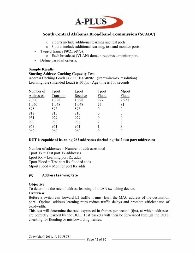
South Central Alabama Broadband Commission (SCABC)
Copyright © 2011, A-PLUSCSI
Page 45 of 80
o 2 ports include additional learning and test ports.
o 3 ports include additional learning, test and monitor ports.
• Tagged frames (802.1p&Q).
o Each broadcast (VLAN) domain requires a monitor port.
• Define pass/fail criteria.
Sample Results
Starting Address Caching Capacity Test
Address Caching Loads is 2000:100:4096:1 (start:min:max:resolution)
Learning rate (Intended Load) is 50 fps - Age time is 300 seconds
Number of Tport Lport Tport Mport
Addresses Transmit Receive Flood Flood
2,000 1,998 1,998 977 2,931
1,050 1,048 1,048 27 81
575 573 573 0 0
812 810 810 0 0
931 929 929 0 0
990 988 988 2 6
963 961 961 1 3
962 960 960 0 0
DUT is capable of learning 962 addresses (including the 2 test port addresses)
Number of addresses = Number of addresses total
Tport Tx = Test port Tx addresses
Lport Rx = Learning port Rx adds
Tport Flood = Test port Rx flooded adds
Mport Flood = Monitor port Rx adds
9.89.89.89.8 Address Learning Rate
Objective
To determine the rate of address learning of a LAN switching device.
Overview
Before a switch can forward L2 traffic it must learn the MAC address of the destination
port. Optimal address learning rates reduce traffic delays and promote efficient use of
bandwidth.
This test will determine the rate, expressed in frames per second (fps), at which addresses
are correctly learned by the DUT. Test packets will then be forwarded through the DUT,
checking for flooding or misforwarding frames.
South Central Alabama Broadband Commission (SCABC)
Copyright © 2011, A-PLUSCSI
Page 46 of 80
Learning frames will first be sent into the DUT at a given rate (fps), followed by test
frames. The number of test frames received must match the number sent, without flooding.
If flooding of the frames is received on a third port (the monitor port), or any other port,
then the DUT cannot handle the rate at which learning frames were sent.
If no flooding of the frames occurs, then the test iteration is successful. The rate (fps) of
learning frames can be increased for the next iteration.
The binary search algorithm will determine the maximum rate (fps) for which the DUT
learns addresses.
Measurements are taken of learning frames sent per second, # of addresses used, # of
addresses received and # of addresses flooded.
Test Steps
1. A minimum of three test ports and three DUT ports are required. One test port is the
learning port, another is the test port and the third is the monitor port.
2. Determine an initial rate (fps) at which learning frames are sent to the DUT.
3. Send L2 learning frames from the test equipment to the DUT.
a. One learning frame is sent from the “test” port.
b. ‘N’ learning frames are sent from the “learning” port. Each has the same
destination address but unique source addresses.
Note: The ‘N’ number of learning frames should be the same, or less, than the
maximum address capacity of the DUT as determined in the previous test (Address
Caching Capacity) on Page 43.
Note: Ensure the DUT will not “time out” addresses before the end of each test iteration.
4. At an acceptable rate to the DUT, the test port will transmit ‘N’ test frames using the
same addresses from Step 3b, except with the source/destination addresses reversed (a
single source address, but unique destination address) destined for the learning port.
5. The monitoring port listens for flooded or misforwarded frames.
6. Using a binary search algorithm, determine the maximum learning rate (in fps) of the
DUT.
a. If the number of test frames forwarded to the learning port matches the number
sent by the test port, and there are no flooded frames on any port, then the iteration passes.
Select the next higher learning rate (fps) in the binary search algorithm and repeat steps 3
to 6.
b. If the number of test frames forwarded to the learning port does not match the
number sent by the test port, and/or there are flooded frames on any port, then the iteration
fails. Select the next lower learning rate (fps) in the binary search algorithm and repeat
steps 3 to 6.
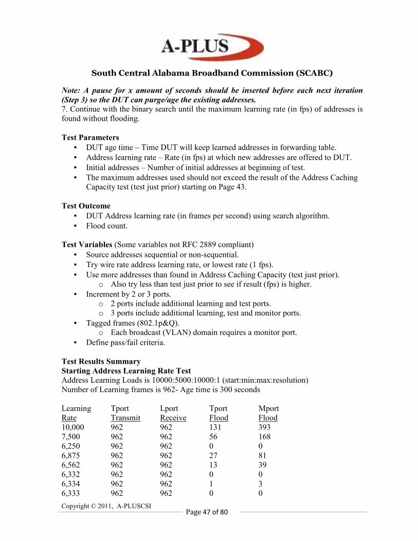
South Central Alabama Broadband Commission (SCABC)
Copyright © 2011, A-PLUSCSI
Page 47 of 80
Note: A pause for x amount of seconds should be inserted before each next iteration
(Step 3) so the DUT can purge/age the existing addresses.
7. Continue with the binary search until the maximum learning rate (in fps) of addresses is
found without flooding.
Test Parameters
• DUT age time – Time DUT will keep learned addresses in forwarding table.
• Address learning rate – Rate (in fps) at which new addresses are offered to DUT.
• Initial addresses – Number of initial addresses at beginning of test.
• The maximum addresses used should not exceed the result of the Address Caching
Capacity test (test just prior) starting on Page 43.
Test Outcome
• DUT Address learning rate (in frames per second) using search algorithm.
• Flood count.
Test Variables (Some variables not RFC 2889 compliant)
• Source addresses sequential or non-sequential.
• Try wire rate address learning rate, or lowest rate (1 fps).
• Use more addresses than found in Address Caching Capacity (test just prior).
o Also try less than test just prior to see if result (fps) is higher.
• Increment by 2 or 3 ports.
o 2 ports include additional learning and test ports.
o 3 ports include additional learning, test and monitor ports.
• Tagged frames (802.1p&Q).
o Each broadcast (VLAN) domain requires a monitor port.
• Define pass/fail criteria.
Test Results Summary
Starting Address Learning Rate Test
Address Learning Loads is 10000:5000:10000:1 (start:min:max:resolution)
Number of Learning frames is 962- Age time is 300 seconds
Learning Tport Lport Tport Mport
Rate Transmit Receive Flood Flood
10,000 962 962 131 393
7,500 962 962 56 168
6,250 962 962 0 0
6,875 962 962 27 81
6,562 962 962 13 39
6,332 962 962 0 0
6,334 962 962 1 3
6,333 962 962 0 0
South Central Alabama Broadband Commission (SCABC)
Copyright © 2011, A-PLUSCSI
Page 48 of 80
DUT is capable of learning addresses at a rate of 6,333 ffps.
Learning Rate = fps rate
Tport Tx = Test port Tx addresses
Lport Rx = Learning Port Rx adds
Tport Flood = Test port Rx flooded adds
Mport Flood = Monitor port Rx adds
9.99.99.99.9 Errored Frame Filtering
Objective
To determine the behavior of the DUT under error or abnormal frame conditions. The
results of the test indicate whether the DUT filters or forwards errored frames.
Overview
Layer 1 and 2 switch errors can cause performance degradation. CRC errors can cause
retries and delays in upper layer protocol exchanges. This test will determine if errored
packets are correctly forwarded, or filtered, through the DUT. The errored packet types are:
• Oversize frames – Frames above 1518 (or 1522 if VLAN tagged) in length.
• Undersize frames – Frames less than 64 bytes in length.
• CRC errored frames – Frames with invalid CRC that fail the Frame Check
Sequence Validation.
• Dribble bit errors – Frames without proper byte boundary.
• Alignment errors – Combination of CRC errored and dribble bit errored frames.
Measurements will be taken of errored frames transmitted and received for each errored
packet type and frame size.
Test Steps
1. A minimum of two test ports and two DUT ports are required.
Note: Groups of two ports can be added to the test if desired.
2. Each test port will emulate a single L2 MAC address.
3. From each test port, send L2 learning frames to the DUT and verify them.
Note: Make sure the DUT will not “time out” addresses before the end of each test
iteration.
4. Using a predetermined load and a 30-second test duration, send unidirectional test traffic
from one test port through the DUT/SUT to the other test port with the following errored
frames:
a. Oversize frames – Frames above 1518 (or 1522 if VLAN tagged) in length.
b. Undersize frames – Frames less than 64 bytes in length.
c. CRC errored frames – Frames with invalid CRC.
South Central Alabama Broadband Commission (SCABC)
Copyright © 2011, A-PLUSCSI
Page 49 of 80
d. Dribble bit errors – Frames without proper byte boundary.
e. Alignment errors – Combination of CRC errored and dribble bit errored frames.
5. The DUT must take the following actions for the above errored frames:
a. Oversize Frames should not be forwarded.
b. Undersize Frames must not be forwarded.
c. CRC errored frames should not be forwarded.
d. Dribble bit errors must be corrected and forwarded.
e. Alignment errors must not be forwarded.
6. Take measurements on the receive side.
a. For each errored packet type, measurements of frames transmitted and received
are recorded.
b. A ‘Pass’ or ‘Fail’ for each errored packet type must be reported.
7. Repeat steps 3 to 6 using various port loads.
Test Parameters
• Errored frames:
o Oversize – Frames above 1518 (or 1522 if VLAN tagged) in length.
o Undersize – Frames less than 64 bytes in length.
o CRC errored frames – Frames with invalid CRC.
o Dribble bit errors – Frames without proper byte boundary.
o Alignment errors – Combination of CRC errored and dribble bit errored
frames.
• Load per port in percentage (%).
• Full or half duplex (10M/100M).
• Each trial (or iteration) is 30 seconds (adjustable from 1–300).
Test Outcome
• Pass/Fail – Fames size used, load, type of errored packet and Tx/Rx statistics.
Test Variables (Some variables are not RFC 2889 compliant)
• Tagged frames (802.1p&Q).
• Use non-errored packets.
• Use errored packet frame sizes: 64, 128, 256, 512, 1024, 1280, 1518.
• IP/UDP header (TOS/TTL/Port#).
• Add multiple port pairs.
Test Results Summary
Starting Errored Frames Test
Frame Length = 64, 20.0% utilization
No-Error Frames Test: Passed
Undersize Frames Test: Passed
Oversize Frames Test: Passed
CRC Errors Test: Passed
South Central Alabama Broadband Commission (SCABC)
Copyright © 2011, A-PLUSCSI
Page 50 of 80
Alignment Errors Test: Passed
Dribble Bits Test: Passed
Frame Length = 64, 30.0% utilization
No-Error Frames Test: Passed
Undersize Frames Test: Passed
Oversize Frames Test: Passed
CRC Errors Test: Passed
Alignment Errors Test: Passed
Dribble Bits Test: Passed
9.109.109.109.10 Broadcast Frame Forwarding and Latency
Objective
To determine the throughput and latency of the DUT when forwarding broadcast traffic.
Overview
This test will determine if the Layer 2 switch can handle broadcast traffic from one-to-
many ports at various traffic loads.
Broadcasts are necessary for a station to reach multiple stations with a single packet when
the specific address of each intended recipient is not known by the sending node. Network
traffic, such as some ARPs, are sent as broadcasts with a MAC destination address of all
Frames. These broadcasts are intended to be received by every port on the DUT. The
performance of broadcast traffic on a switch may be different than the performance of
unicast traffic.
The throughput test will determine the maximum load at which the DUT/SUT will forward
Broadcast traffic without frame loss, as well as the latency of the traffic, for each of the
recommended RFC 2889 frames sizes.
Test Steps
1. A minimum of two test ports and two DUT ports are required. One of the test ports will
transmit broadcast frames and the remaining port(s) will receive the broadcast frames.
2. Each test port will emulate a single L2 MAC address.
3. From each test port, send L2 learning frames to the DUT and verify them.
4. Send broadcast test frames from one test port into the DUT. These frames should be
forwarded through the DUT to every other test port.
5. Run throughput test:
a. Using 64-byte packets, a starting traffic load, and a 30-second test duration, send
broadcast packets as described in Step 4 and determine if all packets are received.
b. Using a binary search algorithm, increase traffic load if no frame loss and
decrease traffic load if frame loss occurs.
c. Continue binary search until maximum traffic load is achieved without frame
South Central Alabama Broadband Commission (SCABC)
Copyright © 2011, A-PLUSCSI
Page 51 of 80
loss.
d. Report the maximum load (throughput) the device successfully forwards without
frame loss.
e. Report the latency of the traffic.
6. Repeat steps 3 to 5 for each remaining recommended frame size: 128, 256, 512, 1024,
1280 and 1518.
Test Parameters
• Frame sizes (including CRC): Recommended are 64, 128, 256, 512, 1024, 1280,
1518.
• Burst size between 1–930 frames (1 = constant load).
• Full or half duplex (10M/100M).
• Load per port in percentage (%).
• Each trial (or iteration) is 30 seconds (adjustable from 1–300).
Test Outcome
• Broadcast frame throughput and latency.
• Per frame size and load.
o Throughput – Maximum load with no frame loss.
o Latency – Average latency.
Test Variables (Some variables not RFC compliant)
• Longer trial/iteration duration.
• Tagged frames (802.1p&Q).
• Use different frame sizes from 64–1518 bytes.
• Use multiple frame sizes in the same test/iteration to simulate realistic traffic.
• IP/UDP header (TOS/TTL/Port#).
• Define Pass/Fail criteria, such as allowing for a small amount of acceptable frame
loss.
Sample Results
Starting Broadcast Frames Throughput and Latency Test
Throughput Test Parameters: Start = 100.0 Min = 0.0 Max = 100.0 Res = 0.5
Frame Length = 64
Offered Load = 76,190,105 bps (100.00% util)
Frame Loss Rate = (0 frames)
Forwarding Rate = 148,808 fps (100.00% util)
Binary search complete:
Throughput is 76,190,105 bps (100.00% util)
Avg Latency is 183.585 microseconds
Frame Length = 128
Offered Load = 86,486,220 bps (100.00% util)
South Central Alabama Broadband Commission (SCABC)
Copyright © 2011, A-PLUSCSI
Page 52 of 80
Frame Loss Rate = (0 frames)
Forwarding Rate = 84,459 fps (100.00% util)
Binary search complete:
Throughput is 86,486,220 bps (100.00% uutil)
Avg Latency is 172.883 microseconds
10 Layer 3 Testing with RFC 2544
10.110.110.110.1 RFC2544/1242 Concepts and Terminology
This section provides an overview of RFC 2544 and RFC 1242 concepts and terminology
that are commonly used throughout the benchmark test.
Device Under Test (DUT)
The DUT is the network interconnect device being tested. This is typically a device that
forwards traffic based on the addresses contained in the Layer 3 header, such as a gateway,
router or Layer 3 switch. The actual physical configuration of the DUT could be a single
chassis with one or more blades or multiple chassis with multiple blades interconnected in
some way. Regardless of the physical configuration, these tests view the DUT as a single
unit with multiple ports. Test results are aggregated over all ports.
Topologies
A test port generates traffic that simulates one or more sources. The simulated source may
be on the same physical network as the DUT port (as in test ports 3 and 4 in the diagram
below) in which case direct delivery is be used. Test ports may also simulate traffic that
originated on a different physical network than the DUT port, so the test port simulates a
network interconnect device (such as a gateway) that forwarded the message (as test ports 1
and 2 in the diagram below). In the second case, the DUT will require routing table entries
to implement indirect delivery. RFC 2544 recommends the DUT immediately learn these
routes using a routing protocol enabled on the DUT. This should be done prior to testing.
RFC 2544 also recommends using the IP address pool 198.18.0.0 through 198.19.255.255,
which have been assigned to the benchmark working group by the IANA. It has further
instructions for assigning DUT port addresses and simulated router addresses on test ports.
Please refer to RFC 2544, Appendix C, for a discussion of IP address assignments.
Another recommendation from RFC 2544 is that tests be run with a single “stream” of
traffic (single Layer 3 source and single Layer 3 destination) and then repeated using Layer
3 destination addresses randomly chosen from a pool. This is reasonable for exercising the
DUT’s route lookup engine.
South Central Alabama Broadband Commission (SCABC)
Copyright © 2011, A-PLUSCSI
Page 53 of 80
Traffic Patterns
RFC 2544 indicates that the ports on the DUT are to be divided into 2 groups, one referred
to as the input port(s) and the other referred to as the output port(s). In the diagram on page
1, DUT ports 1 and 2 have been designated input ports and ports 3 and 4 have been
designated output ports.
RFC 2544 Traffic has the following characteristics:
• For uni-directional traffic, the source and destination addresses in each test frame
should result in frames being routed in an even distribution from each input port to
each output port, and vice versa. This is known as a unidirectional partial mesh.
• For bi-directional traffic, each port is considered a member of both the input and
output groups of ports, so frames from each port are routed in an even distribution
to all other ports. This is known as a bi-directional full mesh.
• The test frames should be routed to the same output port in the same order. For
example, the first test frame arriving at all input ports should all be routed to the
first output port, the second test frame arriving at all input ports should be routed to
the second output port and so on. This ensures that the DUT can handle multiple
frames routed to the same port at the same time.
• If a DUT blade has multiple ports, the ports should be evenly distributed between
the input and output groups
Traffic Content
RFC 2544 specifies the use of UDP echo datagrams (destination Port 7) for IPv4 traffic.
UDP echo datagrams could also be used for IPv6 traffic.
Modifiers
RFC 2544 identifies four modifiers to the benchmark tests. Each modifier describes a
condition likely to exist in “real world” traffic. Each benchmark test defined in RFC 2544
should be run without any modifiers and then repeated under each condition separately.
The modifiers listed are the following:
• Broadcast Frames
• Management Frames
• Routing Update Frames
• Traffic Filters
Network traffic from a modifier should be evenly mixed with test traffic and not supplied
to the DUT through a separate port. The following is a brief description of the four
modifiers listed above. See RFC 2544, Section 1, for more details.
Broadcast Frames
Augment the test frames with 1 percent frames addressed to the hardware broadcast
address. The broadcast frames should be of a type that the DUT will not need to process
internally.
South Central Alabama Broadband Commission (SCABC)
Copyright © 2011, A-PLUSCSI
Page 54 of 80
Management Frames
Augment the test frames with 1 management query at the beginning of each second of test
traffic (such as an SNMP GET for one or more of the MIB-II objects: sysUpTime,
ifInOctets, ifOutOctets, ifInUcastPkts and ifOutUcastPkts). The result of the query should
fit into a single response frame and should be verified by the test equipment.
Routing Update Frames
Augment the test with routing update frames that will change the routing table in the DUT
for routes that will not affect the forwarding of the test traffic. A routing update is sent as
the first frame of each trial. RFC 2544 recommends sending routing update frames every
30 seconds for RIP and each 90 seconds for OSPF. The test should ensure the DUT
processes the routing updates.
Filters
The following should be defined on the DUT. Separate tests should be run for each of the
following two filter conditions:
• Define a single filter on the DUT that permits the forwarding of the test traffic. This
tests basic filter functionality.
• Define 25 filters on the DUT. The first 24 block traffic that will not occur in the test
traffic. The last filter permits the forwarding of test traffic. This ensures filters not
participating in the forwarding test traffic do not negatively impact performance.
10.210.210.210.2 Throughput
Overview
The objective of the throughput test is to determine the throughput of the DUT. Throughput
is defined in RFC 1242 as the maximum rate at which none of the offered frames are
dropped by the device.
Objective
The throughput test determines how well suited a device is to applications in which
minimal frame loss is critical. Some applications, such as voice over IP or video
conferencing require minimal frame loss to be useable. Other applications may be more
tolerant of frame loss, although loss of a single frame may cause response time to suffer
while the upper layer protocols recover from timeouts.
With each trial of the throughput test, test frames are sent at a specific frame rate and the
number of frames forwarded by the DUT is counted. If there is any frame loss, the rate is
decreased; otherwise, the rate is increased. The trials are repeated until the maximum rate is
found at which there is no frame loss. RFC 2544 does not specify an algorithm to
implement, however the most common approach is a binary search algorithm. With the
binary search algorithm, the first trial uses a configured initial frame rate (or percent
utilization). If there is frame loss with a specific trial, the next trial uses a rate calculated as
South Central Alabama Broadband Commission (SCABC)
Copyright © 2011, A-PLUSCSI
Page 55 of 80
the midpoint between the current rate and a configured minimum; otherwise, the next trial
uses a rate calculated as the midpoint between the current rate and a configured maximum.
The test is stopped when the difference between the frame rate of the current and previous
trial is less than or equal to a configured delta.
Test Steps
1. Advertise any routes required by the DUT to allow it to forward test traffic using a
routing protocol supported and enabled on the DUT. Pause several seconds to allow the
routes to update. If all of the destinations reside on physical networks connected to the
DUT, or the DUT has static routes defined, this step may be skipped.
2. Set the current frame length to the first configured frame length.
3. Determine throughput. A typical binary search based algorithm follows:
a. Set current rate to the configured initial frame rate. Set high to the configured
maximum rate and low to the configured minimum rate.
b. Send learning frames (IPv4 ARP or IPv6 Neighbor Discovery, for example).
c. Send test traffic of the current frame length from all test ports for the configured
trial duration at the rate current rate.
d. Calculate frame loss as the number of frames transmitted minus the number of
frames received (aggregated across all test ports).
e. If frame loss is greater than zero (loss occurred), set high to current rate;
otherwise, set throughput and low to current rate.
f. Set delta as (high — low).
g. Set current rate as low + (delta/2).
h. Repeat steps “b” through “g” until either: delta is less than or equal to the
configured precision, or current rate is greater than or equal to high.
4. Report the throughput for the current frame length.
5. Repeat steps 3 through 4 for the remaining configured frame lengths
6. Repeat steps 2 through 5 for each desired modifier. See the Modifiers section above for a
discussion of modifiers.
Variations on RFC 2544
Several common variations exist to RFC 2544 procedures, which include:
• Use a stepwise search, pausing the stepwise search when loss is first encountered to
binary search for throughput. This variation gives a more complete profile of the
DUT in a possibly shorter time (combines the frame loss rate test with the
throughput test).
• Allow a low level of acceptable packet loss instead of requiring zero loss. This may
be used to level the playing field if a particular DUT, due to its architecture, always
loses a small number of frames initially with each trial.
• Add a test iteration with multiple frame lengths that simulate realistic traffic.
• Identify pass/fail criteria and report a general pass or fail indicator.
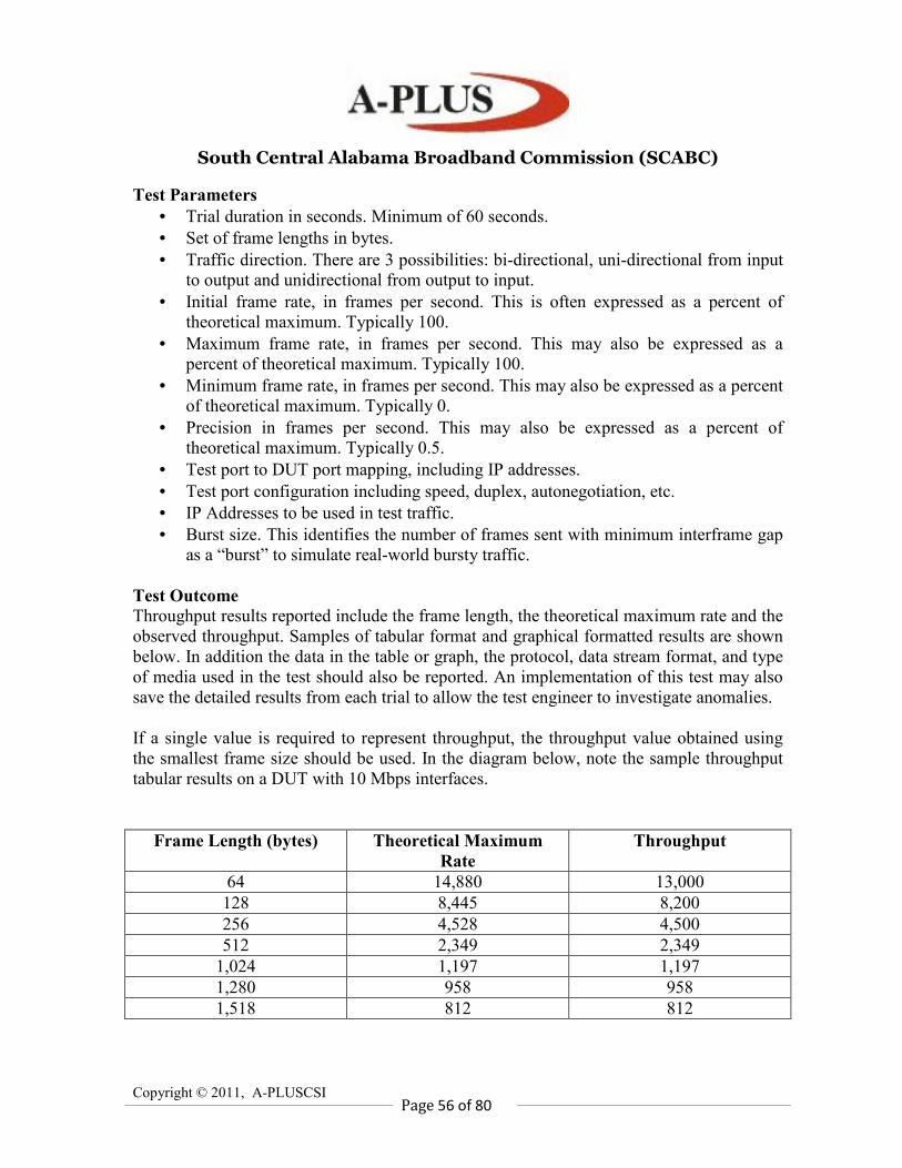
South Central Alabama Broadband Commission (SCABC)
Copyright © 2011, A-PLUSCSI
Page 56 of 80
Test Parameters
• Trial duration in seconds. Minimum of 60 seconds.
• Set of frame lengths in bytes.
• Traffic direction. There are 3 possibilities: bi-directional, uni-directional from input
to output and unidirectional from output to input.
• Initial frame rate, in frames per second. This is often expressed as a percent of
theoretical maximum. Typically 100.
• Maximum frame rate, in frames per second. This may also be expressed as a
percent of theoretical maximum. Typically 100.
• Minimum frame rate, in frames per second. This may also be expressed as a percent
of theoretical maximum. Typically 0.
• Precision in frames per second. This may also be expressed as a percent of
theoretical maximum. Typically 0.5.
• Test port to DUT port mapping, including IP addresses.
• Test port configuration including speed, duplex, autonegotiation, etc.
• IP Addresses to be used in test traffic.
• Burst size. This identifies the number of frames sent with minimum interframe gap
as a “burst” to simulate real-world bursty traffic.
Test Outcome
Throughput results reported include the frame length, the theoretical maximum rate and the
observed throughput. Samples of tabular format and graphical formatted results are shown
below. In addition the data in the table or graph, the protocol, data stream format, and type
of media used in the test should also be reported. An implementation of this test may also
save the detailed results from each trial to allow the test engineer to investigate anomalies.
If a single value is required to represent throughput, the throughput value obtained using
the smallest frame size should be used. In the diagram below, note the sample throughput
tabular results on a DUT with 10 Mbps interfaces.
Frame Length (bytes) Theoretical Maximum
Rate
Throughput
64 14,880 13,000
128 8,445 8,200
256 4,528 4,500
512 2,349 2,349
1,024 1,197 1,197
1,280 958 958
1,518 812 812
South Central Alabama Broadband Commission (SCABC)
Copyright © 2011, A-PLUSCSI
Page 57 of 80
10.310.310.310.3 Frame Latency
Objective
The objective of the latency test is to determine the latency of a frame traversing the DUT.
Overview
There is a significant amount of processing that a router or Layer 3 switch must perform on
each frame. There are fields in the Layer 3 header that must be maintained (such as the
Time To Live) and verified (such as the checksum). Header options that require processing
may exist, such as record route. The destination address must be found in the routing table.
This test helps to ensure that with the ever increasing processing requirements, the time it
takes a DUT to forward a frame is within acceptable limits.
The latency is the amount of time it takes the DUT to start forwarding the frame (first bit of
frame is transmitted) after receiving it. Timestamp T1 is taken when the frame is received
by the DUT and timestamp T2 is taken when the first bit of the frame appears on the output
port. The latency is simply T2 - T1. For a store and forward device, T1 is taken when the
last bit of the frame is received by the DUT. For a bit forwarding device, T2 is taken when
the first bit of the frame is received by the DUT.
Test Steps
1. Advertise any routes required by the DUT to allow it to forward test traffic using a
routing protocol supported and enabled on the DUT. Pause several seconds to allow the
routes to update. If all of the destinations reside on physical networks connected to the
DUT, or the DUT has static routes defined, this step may be skipped.
2. Send learning frames (IPv4 ARP or IPv6 Neighbor Discovery, for example).
3. Set the current frame length to the first configured frame length.
4. Send traffic at a rate of the throughput value (determined in the throughput test) for this
frame length to a specific destination.
5. After 60 seconds, a frame with an identifying tag is included in the transmission.
6. Transmit for the remaining duration of the trial. The time at which the tagged frame is
fully transmitted from the test port is recorded as Timestamp A.
7. The time at which the frame was received at the test port is recorded as Timestamp B.
8. Latency is calculated as B — A and should be adjusted for the type of device (bit
forwarding or store and forward). For bit forwarding devices, subtract the time it takes to
transmit the frame (number of bits x time for one bit).
9. Repeat steps 3 to 8 the configured number of trials and average the latencies from each
trial to get an average.
10. Repeat steps 2 through 9 for the remaining configured frame lengths.
11. Repeat steps 2 through 10 for each desired modifier. See the Modifiers section on Page
53 for a discussion of modifiers.
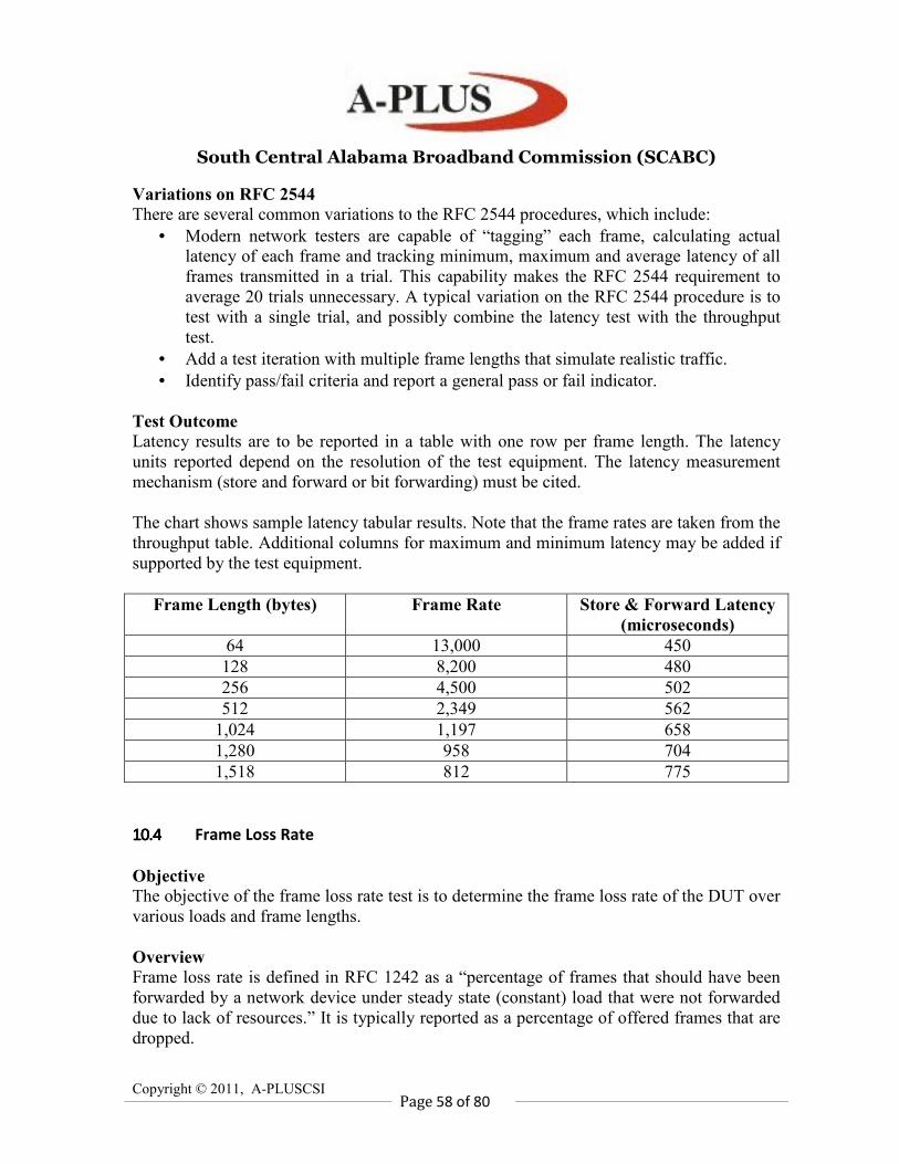
South Central Alabama Broadband Commission (SCABC)
Copyright © 2011, A-PLUSCSI
Page 58 of 80
Variations on RFC 2544
There are several common variations to the RFC 2544 procedures, which include:
• Modern network testers are capable of “tagging” each frame, calculating actual
latency of each frame and tracking minimum, maximum and average latency of all
frames transmitted in a trial. This capability makes the RFC 2544 requirement to
average 20 trials unnecessary. A typical variation on the RFC 2544 procedure is to
test with a single trial, and possibly combine the latency test with the throughput
test.
• Add a test iteration with multiple frame lengths that simulate realistic traffic.
• Identify pass/fail criteria and report a general pass or fail indicator.
Test Outcome
Latency results are to be reported in a table with one row per frame length. The latency
units reported depend on the resolution of the test equipment. The latency measurement
mechanism (store and forward or bit forwarding) must be cited.
The chart shows sample latency tabular results. Note that the frame rates are taken from the
throughput table. Additional columns for maximum and minimum latency may be added if
supported by the test equipment.
Frame Length (bytes) Frame Rate Store & Forward Latency
(microseconds)
64 13,000 450
128 8,200 480
256 4,500 502
512 2,349 562
1,024 1,197 658
1,280 958 704
1,518 812 775
10.410.410.410.4 Frame Loss Rate
Objective
The objective of the frame loss rate test is to determine the frame loss rate of the DUT over
various loads and frame lengths.
Overview
Frame loss rate is defined in RFC 1242 as a “percentage of frames that should have been
forwarded by a network device under steady state (constant) load that were not forwarded
due to lack of resources.” It is typically reported as a percentage of offered frames that are
dropped.
South Central Alabama Broadband Commission (SCABC)
Copyright © 2011, A-PLUSCSI
Page 59 of 80
This frame loss test is useful for establishing a profile of the DUT performance over a
range of frame lengths and loads to ensure consistent performance and graceful
degradation. For example, a DUT may have a throughput of 90 percent of maximum
theoretical bandwidth but degrade to unacceptable performance at 92 percent.
Test Steps
1. Advertise any routes required by the DUT to allow it to forward test traffic using a
routing protocol supported and enabled on the DUT. Pause several seconds to allow the
routes to update. If all destinations reside on physical networks connected to the DUT, or
the DUT has static routes defined, this step may be skipped.
2. Set the current frame length to the first configured frame length.
3. Set the current frame rate to 100 percent of the maximum rate for the current frame size.
4. Send learning frames (IPv4 ARP or IPv6 Neighbor Discovery, for example).
5. Send a specific number of frames at the current rate for this frame length for the
configured duration (frame count may be calculated from duration or vice versa).
6. Calculate frame loss rate as: ((frames transmitted — frames received) x 100/frames
transmitted). Frame counts are aggregated over all test ports.
7. Repeat steps 4 through 6 decrementing the current frame rate by the configured step
value until either the current rate is less than the configured minimum rate or there are two
successive trials during which no frames are lost.
8. Repeat steps 3 through 7 for the remaining configured frame lengths.
9. Repeat steps 2 through 8 for each desired modifier. See the Modifiers section on Page 2
for a discussion of modifiers.
Variations on RFC 2544
There are several common variations to the RFC 2544 procedures, which include:
• Add a test iteration with multiple frame lengths that simulate realistic traffic.
• Identify pass/fail criteria and report a general pass or fail indicator.
Test Parameters
• Trial duration in seconds. Minimum of 60 seconds. If this value is configured, the
number of frames to transmit is calculated.
• Number of frames to transmit. Minimum is the number of frames that result in a 60-
second trial duration. If this value is configured, the trial duration is calculated.
• Set of frame lengths in bytes.
• Traffic direction. There are 3 possibilities: bi-directional, uni-directional from input
to output and unidirectional from output to input.
• Minimum frame rate in frames per second. This may also be expressed as a percent
of theoretical maximum. Typically 0.
• Step frame rate in frames per second. This may also be expressed as a percent of
theoretical maximum. Maximum of 10 percent of maximum rate. Less than 10
percent is recommended.
• Test port to DUT port mapping including IP addresses.
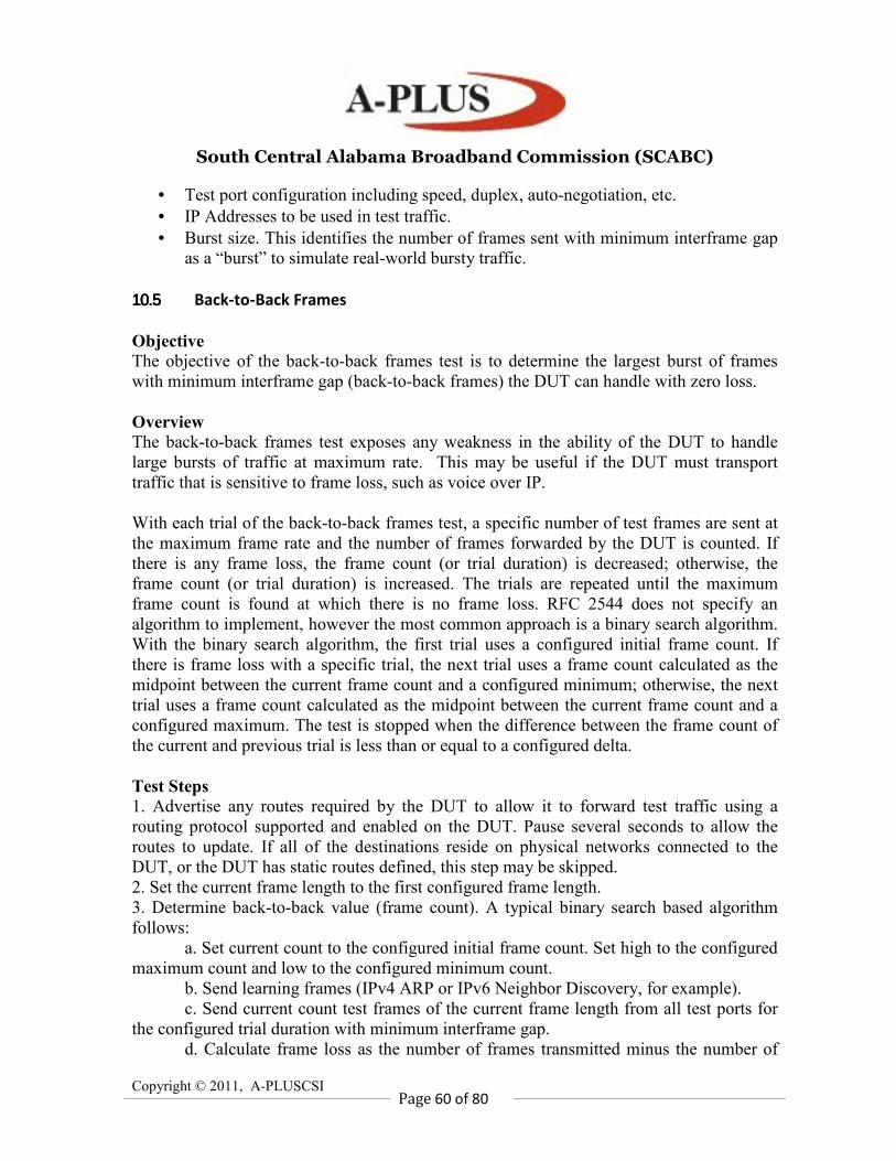
South Central Alabama Broadband Commission (SCABC)
Copyright © 2011, A-PLUSCSI
Page 60 of 80
• Test port configuration including speed, duplex, auto-negotiation, etc.
• IP Addresses to be used in test traffic.
• Burst size. This identifies the number of frames sent with minimum interframe gap
as a “burst” to simulate real-world bursty traffic.
10.510.510.510.5 Back-to-Back Frames
Objective
The objective of the back-to-back frames test is to determine the largest burst of frames
with minimum interframe gap (back-to-back frames) the DUT can handle with zero loss.
Overview
The back-to-back frames test exposes any weakness in the ability of the DUT to handle
large bursts of traffic at maximum rate. This may be useful if the DUT must transport
traffic that is sensitive to frame loss, such as voice over IP.
With each trial of the back-to-back frames test, a specific number of test frames are sent at
the maximum frame rate and the number of frames forwarded by the DUT is counted. If
there is any frame loss, the frame count (or trial duration) is decreased; otherwise, the
frame count (or trial duration) is increased. The trials are repeated until the maximum
frame count is found at which there is no frame loss. RFC 2544 does not specify an
algorithm to implement, however the most common approach is a binary search algorithm.
With the binary search algorithm, the first trial uses a configured initial frame count. If
there is frame loss with a specific trial, the next trial uses a frame count calculated as the
midpoint between the current frame count and a configured minimum; otherwise, the next
trial uses a frame count calculated as the midpoint between the current frame count and a
configured maximum. The test is stopped when the difference between the frame count of
the current and previous trial is less than or equal to a configured delta.
Test Steps
1. Advertise any routes required by the DUT to allow it to forward test traffic using a
routing protocol supported and enabled on the DUT. Pause several seconds to allow the
routes to update. If all of the destinations reside on physical networks connected to the
DUT, or the DUT has static routes defined, this step may be skipped.
2. Set the current frame length to the first configured frame length.
3. Determine back-to-back value (frame count). A typical binary search based algorithm
follows:
a. Set current count to the configured initial frame count. Set high to the configured
maximum count and low to the configured minimum count.
b. Send learning frames (IPv4 ARP or IPv6 Neighbor Discovery, for example).
c. Send current count test frames of the current frame length from all test ports for
the configured trial duration with minimum interframe gap.
d. Calculate frame loss as the number of frames transmitted minus the number of
South Central Alabama Broadband Commission (SCABC)
Copyright © 2011, A-PLUSCSI
Page 61 of 80
frames received (aggregated across all test ports).
e. If frame loss is greater than zero (loss occurred), set high to current count;
otherwise, set back-to-back and low to current count.
f. Set delta as (high — low).
g. Set current count as low + (delta/2).
h. Repeat steps b through g until either: delta is less than or equal to the configured
precision, or current rate is greater than or equal to high.
4. Repeat Step 3 the configured number of iterations and average the back-to-back values.
5. Report the averaged back-to-back value for the current frame length.
6. Repeat steps 3 through 5 for the remaining configured frame lengths.
7. Repeat steps 2 through 6 for each desired modifier. See the Modifiers section on Page 53
for a discussion of modifiers.
Variations on RFC 2544
There are several common variations to the RFC 2544 procedures, which include:
• Add a test iteration with multiple frame lengths that simulate realistic traffic.
• Identify pass/fail criteria and report a general pass or fail indicator.
Test Parameters
• Set of frame lengths, in bytes.
• Traffic direction. There are 3 possibilities: bi-directional, uni-directional from input
to output and unidirectional from output to input.
• Initial frame count. This is often expressed as an initial trial duration in seconds and
the application converts it to a frame count based on the frame length and link
speed.
• Maximum frame count. This is often expressed as a maximum trial duration in
seconds and the application converts it to a frame count based on the frame length
and link speed.
• Minimum frame count. This is often expressed as a minimum trial duration in
seconds and the application converts it to a frame count based on the frame length
and link speed. Recommended minimum is 2 seconds.
• Precision frame count. This is often expressed as a duration in seconds and the
application converts it to a frame count based on the frame length and link speed.
• Number of test iterations. The back-to-back test is repeated this many times per
frame length and the results are averaged. Recommended minimum is 50.
• Test port to DUT port mapping, including IP addresses.
• Test port configuration including speed, duplex, auto-negotiation, etc.
• IP Addresses to be used in test traffic.
Test Outcome
Back-to-back test results are reported in a table with a row for each frame length. There is a
column in the table for the frame length and another column for the average frame count.
The table shows back-to-back tabular results from a DUT with 10 Mbps interfaces.
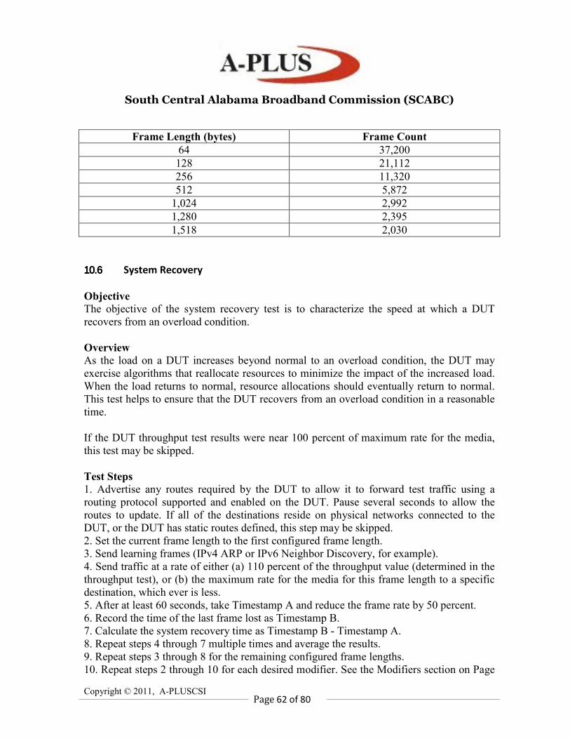
South Central Alabama Broadband Commission (SCABC)
Copyright © 2011, A-PLUSCSI
Page 62 of 80
Frame Length (bytes) Frame Count
64 37,200
128 21,112
256 11,320
512 5,872
1,024 2,992
1,280 2,395
1,518 2,030
10.610.610.610.6 System Recovery
Objective
The objective of the system recovery test is to characterize the speed at which a DUT
recovers from an overload condition.
Overview
As the load on a DUT increases beyond normal to an overload condition, the DUT may
exercise algorithms that reallocate resources to minimize the impact of the increased load.
When the load returns to normal, resource allocations should eventually return to normal.
This test helps to ensure that the DUT recovers from an overload condition in a reasonable
time.
If the DUT throughput test results were near 100 percent of maximum rate for the media,
this test may be skipped.
Test Steps
1. Advertise any routes required by the DUT to allow it to forward test traffic using a
routing protocol supported and enabled on the DUT. Pause several seconds to allow the
routes to update. If all of the destinations reside on physical networks connected to the
DUT, or the DUT has static routes defined, this step may be skipped.
2. Set the current frame length to the first configured frame length.
3. Send learning frames (IPv4 ARP or IPv6 Neighbor Discovery, for example).
4. Send traffic at a rate of either (a) 110 percent of the throughput value (determined in the
throughput test), or (b) the maximum rate for the media for this frame length to a specific
destination, which ever is less.
5. After at least 60 seconds, take Timestamp A and reduce the frame rate by 50 percent.
6. Record the time of the last frame lost as Timestamp B.
7. Calculate the system recovery time as Timestamp B - Timestamp A.
8. Repeat steps 4 through 7 multiple times and average the results.
9. Repeat steps 3 through 8 for the remaining configured frame lengths.
10. Repeat steps 2 through 10 for each desired modifier. See the Modifiers section on Page
South Central Alabama Broadband Commission (SCABC)
Copyright © 2011, A-PLUSCSI
Page 63 of 80
53 for a discussion of modifiers.
Test Parameters
• Set of frame lengths in bytes. All frame lengths for this test must have been used in
the throughput test.
• Traffic direction. There are three possibilities: bi-directional, unidirectional from
input to output and unidirectional from output to input.
• Test port to DUT port mapping, including IP addresses.
• Test port configuration including speed, duplex, auto-negotiation, etc.
• IP Addresses to be used in test traffic.
Test Outcome
System recovery results are to be reported in a table with one row per frame length. There
are columns for the frame length, frame rate and recovery time. The time units reported
depend on the resolution of the test equipment.
Frame Length (Bytes) Frame Rate Recovery Time (ms)
64 14,300 2.800
128 8,445 * 2,750
256 4,528 * 2,730
513 2,349 * N/A
1,024 1,197 * N/A
1,280 958 * N/A
1,518 812 * N/A
The table shows sample system recovery test results. An asterisk (*) next to the frame rate
indicates that the maximum rate for the media was used. A recovery time of N/A indicates
that the test was skipped for this frame size because the observed throughput at the frame
length was equal to the maximum rate.
10.710.710.710.7 Reset
Objective
The objective of the reset test is to characterize the speed at which a DUT recovers from a
device or software reset.
Overview
In the course of normal operations it may be necessary to restart a device. This may be due
to the need to load an alternate configuration, add or swap blades or to clear an error
condition. This test helps to ensure that the DUT resets in a reasonable time.
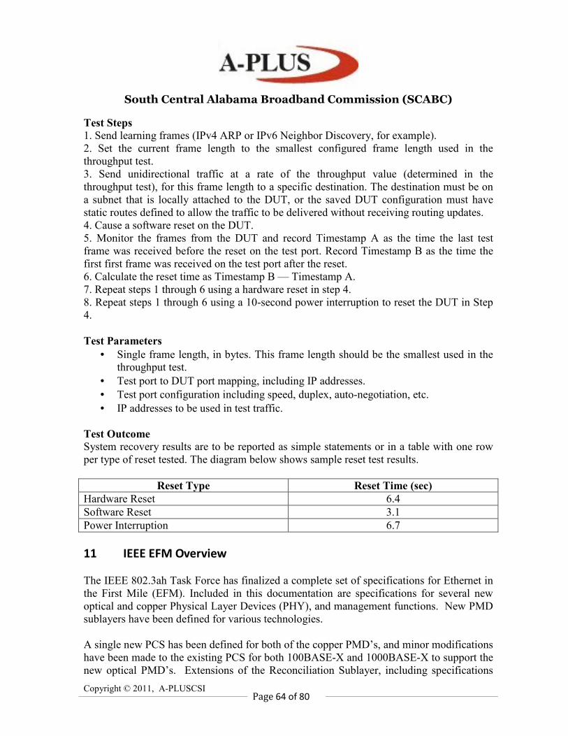
South Central Alabama Broadband Commission (SCABC)
Copyright © 2011, A-PLUSCSI
Page 64 of 80
Test Steps
1. Send learning frames (IPv4 ARP or IPv6 Neighbor Discovery, for example).
2. Set the current frame length to the smallest configured frame length used in the
throughput test.
3. Send unidirectional traffic at a rate of the throughput value (determined in the
throughput test), for this frame length to a specific destination. The destination must be on
a subnet that is locally attached to the DUT, or the saved DUT configuration must have
static routes defined to allow the traffic to be delivered without receiving routing updates.
4. Cause a software reset on the DUT.
5. Monitor the frames from the DUT and record Timestamp A as the time the last test
frame was received before the reset on the test port. Record Timestamp B as the time the
first first frame was received on the test port after the reset.
6. Calculate the reset time as Timestamp B — Timestamp A.
7. Repeat steps 1 through 6 using a hardware reset in step 4.
8. Repeat steps 1 through 6 using a 10-second power interruption to reset the DUT in Step
4.
Test Parameters
• Single frame length, in bytes. This frame length should be the smallest used in the
throughput test.
• Test port to DUT port mapping, including IP addresses.
• Test port configuration including speed, duplex, auto-negotiation, etc.
• IP addresses to be used in test traffic.
Test Outcome
System recovery results are to be reported as simple statements or in a table with one row
per type of reset tested. The diagram below shows sample reset test results.
Reset Type Reset Time (sec)
Hardware Reset 6.4
Software Reset 3.1
Power Interruption 6.7
11 IEEE EFM Overview
The IEEE 802.3ah Task Force has finalized a complete set of specifications for Ethernet in
the First Mile (EFM). Included in this documentation are specifications for several new
optical and copper Physical Layer Devices (PHY), and management functions. New PMD
sublayers have been defined for various technologies.
A single new PCS has been defined for both of the copper PMD’s, and minor modifications
have been made to the existing PCS for both 100BASE-X and 1000BASE-X to support the
new optical PMD’s. Extensions of the Reconciliation Sublayer, including specifications
South Central Alabama Broadband Commission (SCABC)
Copyright © 2011, A-PLUSCSI
Page 65 of 80
for FEC, and a Multi-Point MAC Control Protocol (MPCP) have been written for the
P2MP PMD. Finally, a new section of the document specifies OAM functions and
operations that can be supported by both new EFM devices and traditional 802.3 devices.
Once these specifications are complete, vendors will start selling and marketing compliant
IEEE 802.3ah components and systems. It is important that a comprehensive study be
done to show that interoperability and compliance can and does exist in EFM devices.
Such a study, and related testing, should be initiated while the standard is still in its draft
form, and then continued with an even stronger effort, once the final draft has been
approved and compliant products are ready to be deployed. A set of test suites should be
made publicly available for review and comment that thoroughly describe a group of
conformance and interoperability tests that should be performed on all EFM products.
Several papers have been written to describe the forthcoming EFM specification but there
has not yet been much of a focus on the testing of EFM. Organizations such as the
Ethernet in the First Mile Alliance (EFMA), the PON Forum, and the IEEE EPON Forum,
have all been created to provide forums for the discussion and demonstration of EFM
technologies, yet the development of testing strategies should take a top priority for these
or other organizations. In order to prepare both the vendor and user communities for the
successful deployment of EFM products, such an effort needs to be initiated with input
from all involved parties.
The UNH-IOL has been performing interoperability and conformance testing on various
products for over fifteen years, including various forms of Ethernet testing since 1993,
xDSL testing since 1997 and DOCSIS testing since 1999. These three sets of technologies
are the areas that are the most applicable EFM. The two EFM copper PMD’s are built
upon existing SHDSL and VDSL technology and parts of the control protocol for the
EPON PHY is similar in scope to that used by DOCSIS. Since the set of EFM
specification are being added to IEEE 802.3, there is a clear relation between existing
Ethernet products and EFM. The experience gained by the UNH-IOL from testing these
technologies can be applied to the EFM technologies. The inherent similarities between
EFM and existing technologies can be exploited such that similar methodologies and
metrics may be used to develop tests for EFM devices. A complete list of interoperability
and conformance test suites previously developed by the UNH-IOL can be found at the
UNH-IOL website. These documents may be used as the framework for the testing of EFM
devices.
12 IEEE EFM Testing
In order to formulate a set of strategies for EFM conformance and interoperability testing,
it is necessary to first separate the different aspects of EFM into several distinct groups,
each covering a particular aspect of the technology. Each of these groups needs to be
approached with a slightly different point of view, because although all EFM devices are
South Central Alabama Broadband Commission (SCABC)
Copyright © 2011, A-PLUSCSI
Page 66 of 80
ultimately transmitting and receiving the same IEEE 802.3 MAC frames, the means by
which these frames are communicated can be tested in very different ways. For example,
the test equipment used to perform conformance testing is quite different if testing the
specifications of an optical transceiver or if testing the specifications of a frame-based
protocol. Additionally, it is necessary to separate the concepts of both conformance and
interoperability testing. Each layer of the EFM specification is presented separately, and
considerations are made for the test tools needed to perform conformance testing and the
conditions necessary for interoperability testing.
12.112.112.112.1 EFM OAM Conformance Testing
One of the new features being added to IEEE 802.3 is that of OAM. OAM provides a
mechanism for the monitoring of an Ethernet network, including: remote fault, remote
loopback, and statistics gathering, through a frame based protocol that lies above the MAC
sublayer. Since OAM is a frame-based protocol, any piece of test equipment that
implements the appropriate physical layer may be used to test the OAM functionality.
Although a test suite for OAM conformance testing must be created, the implementation of
such a test suite should be relatively straightforward.
12.212.212.212.2 EFM P2P Protocol Conformance Testing
Both the 100Mb/s and 1000Mb/s P2P EFM solutions are entirely based on existing
specifications. The only modification that needs to be made to existing test equipment is to
replace the existing PMD with one of the newly defined ones. In many instances, this
could be as simple as replacing a pluggable optics module on the test equipment. Existing
test suites and test tools can completely characterize the protocol and coding sublayers of
EFM P2P optical devices.
12.312.312.312.3 EFM EPON Protocol Conformance Testing
The proposed test tools are for conformance verification of EFM P2MP devices. The tool
must be able to exhaustively test a P2MP device’s ability to receive any valid and invalid
bit pattern. The tester should be able to define test scripts, which can be run automatically
or by a manual process. The scripts will enter the processing engine and be placed into the
appropriate format. For example, test scripts used to verify the operation of the PCS will
be handled differently than those used to verify the operation of the OAM sublayer. The
transmit emulator will prepare the actual bit patterns to be transmitted to the Device Under
Test (DUT). A similar emulator will exist on the receive side of the test tool, and all
received bit patterns will be stored and analyzed to determine whether or not the DUT is
operating properly. Additionally, there will exist the ability to trigger on various patterns
that are received by the test tool. These triggering capabilities will also feedback into the
processing engine so that additional patterns may be sent if necessary.
South Central Alabama Broadband Commission (SCABC)
Copyright © 2011, A-PLUSCSI
Page 67 of 80
The transmit emulator of the EPON test tool will be able to create test vectors that can be
inserted at any of the sublayers contained within tool. In order to test frame level
conformance, it is necessary and easiest to create OAM, MAC Control, or MAC Client
frames that can be transmitted to the DUT. The ability to generate such frames, and the
ability to modify the contents of the frames should allow for any frame based protocol
testing that needs to occur. The OLT and/or ONU functions, allow the test tool to generate
any valid or invalid frame necessary for testing aspects of the MPCP, including REPORT
and GATE messages, which allow the ONU to request and the OLT to grant access to the
network, and the appropriate timestamps that are necessary for the protocol. The block
containing the MAC functions has the ability to behave like a valid or invalid MAC,
including modifying the contents of the preamble fields, as shown in Figure 3. The PHY
part of the test tool needs the ability to generate arbitrary 8-bit or 10-bit streams to be sent
to the DUT, allowing for the ability to thoroughly test the coding layers of the DUT. In
order to test each defined interface in a comprehensive manner, it is necessary for the test
tool to allow access to each layer. Although additional tools may have the ability to test
one or more of these interfaces, the most effective test tool will allow for the generation of
any one of these test vectors.
Even though an EPON device uses a PCS and MAC that are identical to the ones used by
1000BASE-X devices, the EPON device does have a different RS. It is because of the
existence of this different sublayer that traditional gigabit ethernet test equipment cannot be
used to properly test an EPON frame. Although most of the fields are identical to that of a
1000BASE-X frame, there is a significant difference in the contents of the first part of the
frame, the preamble. In a traditional device, this field would contain seven bytes of 0x55
and a single eighth byte of 0xD5.
For EPON devices, the preamble contains a significant amount of information. Four bytes
of the preamble have been left unaltered and will still be transmitted as 0x55. The third
byte of preamble contains a Start of Packet Delimiter (SPD) that is transmitted as 0xD5.
The sixth and seventh bytes are replaced with a Logical Link ID (LLID) that contains the
LLID and mode bit associated with either an ONU or the OLT. A unique LLID is assigned
by the OLT to each ONU once the registration process is complete. The RS of the ONU
will filter frames based on the value of the LLID field in the preamble. This was a
necessary feature to add to the EFM specifications in order to allow for the architecture of
the PON. For example, in a typical shared ethernet network, a device that transmits a
frame will not receive the exact frame that it transmitted. A repeater or switch will forward
a frame out all ports other than the port on which it was received. The nature of the PON
makes this impossible. The OLT can be placed in a mode that will force it to forward all
frames it receives from one ONU to all other ONU’s. Doing this will mean that the
initiating ONU will receive its own frame. Whereas this could potentially cause problems
in a traditional ethernet network, the filtering that takes place in the RS using the modified
preamble will prevent the originating MAC from receiving its own frames. Although most
existing test equipment does not allow the user to modify these fields, the EPON test tool
will need the ability to set the contents of the preamble to an arbitrary value.
South Central Alabama Broadband Commission (SCABC)
Copyright © 2011, A-PLUSCSI
Page 68 of 80
All of these features will be necessary for the creation of the EPON test tool. From the
ability to modify the preamble of the data frame to defining specific 10-bit streams to send
to the DUT on the transmit side, and the ability to receive and decode the DUT’s
transmissions at variety of interfaces including raw 10-bit, decoded 8-bit, and at the frame
level on the receive side, the EPON test tool will allow the tester to thoroughly test any of
the protocol and coding aspects of an EPON device. The numerous state machines, PICS
items, and other mandatory portions of the specification can be tested with this tool.
12.412.412.412.4 EFM Optical PMD Conformance Testing
IEEE 802.3 has traditionally provided detailed descriptions or references for making the
necessary optical PMD measurements. The EFM specifications continue this trend, by
specifying test patterns and methodologies for each of the conformance tests, including
Transmit Dispersion Penalty (TDP), eye mask, jitter, stressed receiver, and others. One
new addition to the EFM set of specifications is the definition of user-definable test frames.
Previous IEEE 802.3 specifications have specified specific test sequences or frames, which
have not been patterns normally allowed on a functioning link. The new specifications
allow for all of the PMD measurements to be made on patterns that can readily be found
and generated on an active network, including jitter test frames that have user defined
fields to allow for their propagation through the network. Other tests may be made while
generating normal idle patterns or validly formed frames instead of placing the DUT into a
special test mode that may or may not be available to the tester.
12.512.512.512.5 EFM OAM Interoperability Testing
OAM interoperability testing may be performed between any set of devices that share the
same physical layer. As previously stated, the three main functions of OAM are: remote
fault indication, remote loopback, and statistics gathering. Separate test conditions will
exist for each of these functions in order to properly verify interoperability.
When two devices are first connected together, the OAM protocol goes through a
handshaking protocol, called the discovery process, to configure and initialize the OAM
link. During this process, the two devices exchange OAM frames indicating the OAM
features and capabilities that are supported by each device. When both devices are
satisfied with each other, the discovery process ends and the rest of the protocol takes over.
Two devices that support OAM should be able to complete the discovery process with each
other. The test setup is as simple as connecting the devices over the appropriate channel
and attaching monitoring stations so that the transmissions from each device can be
observed. The monitoring stations should observe both link partners going through the
discovery process. Following the discovery process, the remote loopback and statistics
querying functionalities can be initiated.
When the link conditions deteriorate, such that one of the devices loses link on its receive
side, it is allowed to indicate a remote fault to its link partner. Traditionally, an Ethernet
South Central Alabama Broadband Commission (SCABC)
Copyright © 2011, A-PLUSCSI
Page 69 of 80
device has not been able to send frames unless a full link has been established with its link
partner. Therefore, if a problem existed in the receive path of one of the two devices, no
other information would be made available to the network operator other than the fact that
the link had not been established. For EFM, however, new additions have been made to
allow this type of unidirectional traffic to exist on the link. To test remote fault indication
interoperability, it is necessary to degrade the receive path of one of the link partners and
verify whether or not the other link partner has been successfully made aware of the remote
fault. The test setup can then be reversed to check operation for the other device. The
remote fault indication may be advertised in the management entities available for each
device.
Remote loopback provides a mechanism for the remote device to be placed in a frame level
loopback mode. All data frames sent from the local device to the remote device will be
looped back at the OAM sublayer to the local device where the frames can be analyzed to
provide information about the quality of the link. While a device is placed in loopback
mode, although no MAC Client frames may be transmitted, MAC Control frames and
OAM frames may be transmitted as necessary. Since placing a remote device into a
loopback mode is such an invasive feature of OAM, not all devices are allowed to be
placed into such a mode. For devices that do support the loopback feature, it is important
to verify that the remote link partner can place them into this mode.
The other main objectives of OAM are those of event notification and the request and
response of variables. Event notification allows the local device to signal to the remote
device when certain events have occurred. The various events that can be signaled include:
errored symbols and frames in a given window, error thresholds that have been crossed,
total number of errors, and others. In addition to the event notification, there exists the
ability for a local device to query the variables and registers of the remote device. For full
interoperability to exist, one device must be able to successfully query and receive a
response from its remote link partner.
12.612.612.612.6 EFM P2P Interoperability Testing
Interoperability of EFM P2P optical devices should be verified over the worst-case optical
channel that is defined within the specification. This optical channel can be characterized
by the attenuation and dispersion of the fiber lengths, and by the insertion loss and return
loss characteristics of the connectors. Whereas many of the conformance measurements
are made over a short length of fiber, the interoperability tests should be performed over
this worst-case channel. Under the worst-case conditions, the two link partners are
required to establish and maintain the link with a BER of at least 10-12. Once the link has
been acquired, the easiest way to measure the BER is to transmit a set of frames between
the two devices. Using validly formed frames allow for each part of the system to be tested,
from the optical modules, to the coding and framing chips, to the higher layer capabilities
of the device. Such a full system test is inherently more effective at establishing
interoperability for the whole system than a simpler component-to-component test.
South Central Alabama Broadband Commission (SCABC)
Copyright © 2011, A-PLUSCSI
Page 70 of 80
12.712.712.712.7 EPON Interoperability Testing
Once conformance testing has been completed on an EPON OLT or ONU, interoperability
testing should be completed between the DUT and other available link partners. Each OLT
can be connected to the available ONU devices that are present, and each ONU will be
connected to the available OLT devices. There are a number of important tests to be
performed to verify interoperability, including both physical layer and protocol layer tests.
When an ONU is first connected to the EPON, it cannot immediately begin transmitting
data, as it would be able to do on a P2P network. Instead, it must first wait for a
registration period to begin and attempt to register itself with the OLT. Periodically, the
OLT will open registration periods during which all new or currently unregistered ONU’s
may attempt to join or rejoin the network. This registration, or discovery, process is the
only time that more than one ONU is allowed to transmit at the same time. All other ONU
transmissions occur during time slots that are granted individually to the ONU by the OLT.
Although certain measures are taken to reduce the number of collisions that may occur
during this process, it is inevitable that they will occur, thus introducing the first potential
interoperability problem. Since the algorithms defining when and for how long each
registration period will exist are left up to the implementer, it is possible that certain
implementation may be more prone to interoperability problems than others. If collisions
occur too frequently, it is possible that the ONU may not be able to register with the OLT
and join the EPON. Thus, attempting to connect the maximum number of ONU’s to the
EPON at the same time should be one condition that is tested for. In such a worst-case
scenario, as would potentially happen if a given EPON were to lose and then regain power,
the OLT needs to allow each ONU to register, and the ONU needs to be able to properly
register with the OLT.
Once the registration process is complete, each ONU will be connected to the EPON and
will have the ability to transmit and receive data frames. The OLT will periodically
transmit grant, or GATE, frames to each ONU that indicate one or more time slots during
which the particular ONU may transmit frames. It is only during this period that the ONU
is allowed to transmit frames to the OLT. The ONU may transmit data frames along with
request, or REPORT, frames that ask for a future blocks of time during which additional
data frames may be transmitted. This process of the OLT granting the ONU time to
transmit and the ONU asking for time to transmit is the underlying protocol that keeps the
EPON running and allows for data frames to be transmitted by the ONU. The mechanism
by which the bandwidth of the EPON is allocated is again undefined by the specification
and left up to the implementers. Testing must be done to ensure that any ONU can
properly communicate with any OLT and that the ability for the ONU to transmit frames is
granted as necessary.
Apart from interoperability at the protocol layer, a significant amount of testing also needs
to be done at the physical layer. As described in IEEE 802.3 Clause 66 the OLT and ONU
may be connected in one of several topologies, including single splitter, tree and branch,
South Central Alabama Broadband Commission (SCABC)
Copyright © 2011, A-PLUSCSI
Page 71 of 80
and serial. Tradeoffs may be made between the fiber length and number of splitters,
provided that the overall link budget is met. The worst-case optical channel can then
include a variety of different topologies depending on which test is being performed. For
example, to test the ability of an ONU to communicate with an OLT over a channel
providing the worst-case physical signaling, a high split ratio long length of fiber should be
used. This will allow for the greatest deterioration of the signal. In order to test
interoperability between an ONU and OLT that support the optional FEC, this is precisely
the necessary environment, and care should be made to stress the environment so that the
worst-case BER can be achieved. Other tests may call for ONU’s to be all situated at the
same length from the OLT, either near or far, or to be positioned so that they are maximally
far apart from each other. Since multiple topologies will be deployed, it is important that
all ONU and OLT devices be tested over a variety of network structures and verified to
properly implement the protocol and allow data transmission at the required BER.
13 Conclusion
In the days of time-division multiplexing (TDM) and DS1/DS3/2M dedicated circuits, bit-
error-rate (BER) testing was the methodology of choice because the quality of a circuit was
easily judged by its capability to deliver error-free bits.
Unfortunately, there are multiple issues related to using BER testing in Ethernet-based
networks. Because Ethernet is a Layer 2 switched technology, a hardware loopback might
not be the perfect test approach. The integrity of an Ethernet frame is verified at each
switching element, and a single bit error will result in the entire frame being discarded.
The errored bit will never get to the analyzer and the analyzer will declare a frame loss.
For this reason, the standard BER test is no longer sufficient for performance testing of
Ethernet networks, and network element manufacturers and service providers quickly
adopted the RFC 2544 methodology as the de facto standard for Ethernet-based testing.
Although testing Ethernet services according to the RFC 2544 standard can be time-
consuming, today’s test equipment automates test sequences and is easily configured to
provide pass/fail criteria. RFC 2544-based Ethernet test solutions provide service
providers with the means to fully validate and benchmark their Ethernet network through
comprehensive testing and reporting—critical components when establishing performance
metrics for customer SLAs and when troubleshooting or maintaining deployed circuits.
It is well understood that the success of any technology depends, in part, on the ability of
the components to interoperate with each other and the ability of the components to
conform to a defined specification. The most effective way to demonstrate interoperability
and conformance is through comprehensive testing that is based on accepted
methodologies and conditions. The development of specific test tools is necessary to fully
test the conformance of a particular technology or protocol, as generic tools may not have
South Central Alabama Broadband Commission (SCABC)
Copyright © 2011, A-PLUSCSI
Page 72 of 80
the ability to do this. When testing for conformance, it is just as important to determine
how a device reacts to the data it should receive, as it is to know how the device reacts to
the data it should not receive. Specialized test tools allow the tester to generate arbitrary
bit patterns to fully test the conformance of coding and protocol layers. Interoperability
testing demonstrates whether or not sets of devices can operate with each other under
specified conditions, while maintaining a minimum level of performance. As the number
of implementations increases, so does the need for interoperability testing.
The EFM specifications being written by the IEEE 802.3ah Task Force define the behavior
of multiple sublayers and the interfaces these layers have with each other. Tests can be
drawn up from these specifications as the initial documents by which to judge conformance
and interoperability. It is recognized that the EFM specifications do not cover all necessary
features of the technology including but not limited to security, quality of service, and
bandwidth allocation. For those aspects of EFM that are not currently defined, it is
imperative for the industry to come together and set forth specific guidelines and test
requirements that need to be followed. Although the successful testing of conformance and
interoperability for EFM devices will not guarantee the success of the technology, it is an
important first and continual step towards that end.
14 References
10 Gigabit Ethernet Alliance
http://www.10gea.org/
Airspan
http://www.airspan.com/
American Registry for Internet Numbers (ARIN)
https://www.arin.net/
Carrier Ethernet World Congress
http://www.carrierethernetworld.com/
ECI Telecom
http://www.ecitele.com/Products/9000Family/9700S/Pages/default.aspx
Enablence
http://www.enablence.com/access/product-lines/trident7
South Central Alabama Broadband Commission (SCABC)
Copyright © 2011, A-PLUSCSI
Page 73 of 80
European Advanced Networking Test Center
http://www.eantc.com/
Federal Communications Commission (FCC)
http://www.fcc.gov/
IEEE Standards Association
http://standards.ieee.org/index.html
Internet Engineering Task Force
http://www.ietf.org/
Inter-Operability Lab at The University of New Hampshire
http://www.iol.unh.edu/
IXIA Carrier Ethernet Library
http://www.ixiacom.com/solutions/testing_carrier_ethernet/library/index.php
Joint Interoperability Test Community
http://jitc.fhu.disa.mil/
Metro Ethernet Forum
http://metroethernetforum.org/index.php
Network Vendors Interoperability Testing Forum (NVIOT)
http://www.nviot-forum.org/
Public Safety Communications Research (PSCR)
http://www.pscr.gov/
South Central Alabama Broadband Commission (SCABC)
Copyright © 2011, A-PLUSCSI
Page 74 of 80
15 Glossary
A
Address Caching Capacity - The number of MAC addresses a DUT/SUT can cache and
successfully forward frames to without flooding or dropping frames.
Address Learning Rate - The highest rate that a switch can learn new MAC addresses
without flooding or dropping frames.
Address Resolution Protocol (ARP) - A mechanism used with IPv4 to translate an IP
address into a MAC address.
B
Backpressure - Any technique used by a DUT/SUT to attempt to avoid frame loss by
hindering external traffic sources from transmitting frames to congested interfaces.
Back-to-Back - Frames presented “back-to-back” have a minimum legal IFG for the given
medium over a small-to-medium period of time. From RFC 1242: Fixed length frames
presented at a rate where the minimum legal separation for a given medium between
frames over a short to medium period of time, starting from an idle state.
Bidirectional Traffic - Frames presented to a DUT/SUT from all directions, with every
receiving interface also transmitting.
Bit Forwarding Device - A device that begins to forward a frame before the entire frame
has been received. Typically this is called a switch.
Bridge - A device that forwards data frames based on information in the data link layer.
Bridge/Router- A bridge/router is a network device that can function as a router and/or a
bridge based on the protocol of a specific packet.
Broadcast Forwarding Rate - The number of broadcast frames per second that a
DUT/SUT can be observed to successfully deliver to all interfaces in response to a
specified offered load of frames directed to the broadcast MAC address.
Broadcast Latency - The time required by a DUT/SUT to forward a broadcast frame to
each interface.
Burst Size - The number of frames sent back-to-back at the minimum legal IFG.
C
South Central Alabama Broadband Commission (SCABC)
Copyright © 2011, A-PLUSCSI
Page 75 of 80
Carrier-Sensing Multiple-Access with collision detection (CSMA/CD) - CSMA/CD is
used to improve CSMA performance by terminating transmission as soon as a collision is
detected, thus reducing the probability of a second collision on retry.
Constant Load - Fixed length frames at a fixed interval time. Typically, these are back-to-
back frames sent at the minimum IFG for the duration of the test.
Cyclic Redundancy Check (CRC) - A number derived from, and stored or transmitted
with, a block of data in order to detect corruption.
D
Device Under Test (DUT) - The device being tested. The forwarding device to which test
packets are offered and the response measured.
Direct Delivery - An IP delivery mechanism in which the sender may deliver a frame
directly to the receiver.
E
Errored Frames - Frames having errored conditions. These conditions could include
oversized, undersized, misaligned or with an errored Frame Check Sequence.
F
Flood Count - The flood count is the number of frames output from a DUT port that are
not specifically addressed (destination MAC) to a device connected to the port.
Forward Pressure - Methods that violate a protocol to increase the forwarding
performance of a DUT/SUT. This can be accomplished by using a smaller IFG than the
protocol calls out.
Forwarding Rate (FR) - The forwarding rate is reported as the number of test frames per
second the DUT successfully forwarded.
Forwarding Rate as Maximum Offered Load (FRMOL) - The observed FR at the
maximum OLoad. Note that the maximum OLoad may not have occurred in the test
iteration with the maximum ILoad.
Frame Based Load - The frame based load mechanism calculates the number of frames
that should be transmitted given the port load (percent utilization) and test duration. The
frames are then transmitted and the transmission is allowed to complete, regardless of the
elapsed time. The frame based load mechanism is limited in this implementation because
the OLoad cannot be properly calculated. The OLoad reported with this mechanism will
always equal the ILoad. This mechanism should only be used when the DUT is not allowed
to implement any congestion control mechanism and there are no half duplex links that will
carry bidirectional traffic. Also see: Port Loading, Time-Based Load.
South Central Alabama Broadband Commission (SCABC)
Copyright © 2011, A-PLUSCSI
Page 76 of 80
Frame Loss Rate (FLR) - Percentage of frames that were not forwarded by the DUT, that
were not forwarded due to lack of resources.
Full Duplex - A transmission path able to transmit signals in both directions
simultaneously.
Fully Meshed Traffic - Frames offered to a DUT/SUT such that each interfaces receives
frames addressed to all other interfaces in the test.
G
Gateway - A network interconnect device that typically forwards frames based on network
(Layer 3) addressing. Similar to a router.
H
Half Duplex - A transmission path capable of transmitting signals in both directions, but
only in one direction at a time.
Head Of Line Blocking (HOLB) - Frame loss or increased delay on an uncongested
output port when frames are received from an input port that is also attempting to forward
frames to a congested output port.
I
IBG - Interburst Gap. The gap between bursts.
IFG - Interframe Gap. The gap between frames on the Ethernet wire.
ILoad - Intended Load. The number of frames per second that the test equipment attempts
to transmit to a DUT/SUT.
Indirect Delivery - An IP delivery mechanism in which the sender may not deliver a frame
directly to the receiver but instead delivers it to the next network interconnect device in the
path.
Internet Assigned Numbers Authority (IANA) - An organization responsible for
managing all numbers assigned to Internet protocols.
Internet Protocol (IP) - The network (Layer 3) protocol of the TCP/IP protocol suite.
L
Latency - For store and forward devices: The time starting when the last bit of the input
frame reaches the input DUT port and ending when the first bit of the output frame is seen
on the output DUT port. For bit forwarding devices: The time interval starting when the
end of the first bit of the input frame reaches the input DUT port and ending when the start
South Central Alabama Broadband Commission (SCABC)
Copyright © 2011, A-PLUSCSI
Page 77 of 80
of the first bit of the output frame is seen on the output DUT port.
Layer 3 Switch - A network interconnect device that forwards frames based on network
(Layer 3) addressing using the bit forwarding mechanism.
M
Management Information Base II (MIB-II) - A specification of management objects.
Maximum Forwarding Rate (MFR) - The highest forwarding rate of a DUT/SUT taken
from iterations of forwarding rate measurement tests.
Maximum Offered Load (MOL) - The highest number of frames per second that an
external source can transmit to a DUT/SUT for forwarding to a specified output
interface(s).
Media Access Control (MAC) - The lower sublayer of the OSI data link layer. The
interface between a node’s Logical Link Control and the network’s physical layer.
N
Neighbor Discovery - A mechanism used with IPv6 to translate an IP address into a MAC
address.
Non-Meshed Traffic - Frames offered to a single DUT port and addressed to a single
output DUT port.
O
OLoad - The number of frames per second that the test equipment can be observed or
measured to transmit to a DUT/SUT for forwarding to a specified output interface or
interfaces. The OLoad may be less than the ILoad if the DUT implements a congestion
control mechanism such as pause frames, or if one or more links are running in half duplex
mode with bidirectional traffic.
Open Shortest Path First (OSPF) - A link-state routing protocol.
Overhead Behavior - Processing performed for other than normal data frames.
Overloaded Behavior - When demand exceeds available system resources.
P
Packet Buffer A temporary repository for arriving packets while they wait to be processed.
Packet Processor Optimized application-specific integrated circuit (ASIC) or programmable device (NPU)
South Central Alabama Broadband Commission (SCABC)
Copyright © 2011, A-PLUSCSI
Page 78 of 80
for processing and forwarding packets in the data plane or fast path. It performs specific
key tasks such as parsing the header, pattern matching or classification, table lookups,
packet modification, and packet forwarding, ideally at wire speed.
Partially Meshed Traffic - Frames offered to one or more DUT ports and addressed to
one or more output DUT ports, where input and output ports are mutually exclusive and
mapped one-to-many, many-to-one or many-to-many.
Passive Optical Network (PON) A point-to-multipoint, fiber to the premises network architecture in which unpowered
optical splitters are used to enable a single optical fiber to serve multiple premises. The
PON consists of an Optical Line Terminal (OLT) at the service provider’s central office
and a number of Optical Network Units (ONUs) near the End Users.
Physical Coding Sublayers (PCS)
Defines the physical layer specifications(speed and Duplex modes etc..) for networking
protocols like Fast Ethernet, Gigabit Ethernet and 10 Gigabit Ethernet. This sublayer
performs auto-negotiation and coding such as 8b and 10b encoding which is a telecom line
code that maps 8-bit symbols to 10-bit symbols in order to achieve balance and bounded
disparity to provide enough state changes to allow reasonable clock recovery.
Physical Media Attachments (PMA)
Provides the physical media independence necessary to support various physical media.
PMA sends and receives serialised bits to and from the Physical Medium Dependent
(PMD) sublayer in Non-Return to Zero (NRZ) line coding. PMA also recovers the clock
from the data signal received. In a local area network, PMA represents that portion of the
physical layer implemented by the functional circuitry of the Medium Attachment Unit
(MAU).
Physical Medium Dependent (PMD)
Defines the physical layer specifications in Gigabit and 10 Gigabit Ethernet transmissions.
It is responsible for the transmission and reception of individual bits on a physical medium.
These responsibilities encompass bit timing, signal encoding, interacting with the physical
medium, and the cable or wire itself.
Port Loading - RFC 2889 defines two approaches to loading a DUT port with test traffic.
The objective of these modes is to be able to measure the OLoad. The two methods are (a)
Time Based Load – Send test traffic for a specific time interval, and (b) Frame Based Load
- Send a specific number of frames.
R
Request For Comments (RFC) - A document published by the Internet Engineering Task
Force that may define a standard after passing through several phases of acceptance.
South Central Alabama Broadband Commission (SCABC)
Copyright © 2011, A-PLUSCSI
Page 79 of 80
Reset - An action resulting in the re-initialization of a device.
Router - A network device that forwards frames based on network (Layer 3) addressing.
Routing Information Protocol (RIP) - A distance-vector interior routing protocol.
S Store and Forward Device - A network interconnect device that receives an entire frame
before beginning to forward it.
Synchronized Optical Network (SONET) SONET is a standard for optical transport. It allows different types of formats to be
transmitted on one line.
System Under Test (SUT) - The device/system being tested. Two or more DUTs
networked together to which test packets are offered and the response measured.
T
Throughput - The maximum rate at which none of the offered frames are dropped by the
device.
Time-Based Load - The time based load mechanism is the preferred mechanism if there is
any possibility of the DUT using a congestion control mechanism. With this mechanism,
the test duration is strictly enforced. If any congestion control mechanism is used by the
DUT or any links are half duplex with bidirectional traffic, the OLoad may be less than the
ILoad. Also see: Port Loading, Frame-Based Load
Time Division Multiplexing (TDM) A method of putting multiple data streams in a single signal by separating the signal into
many segments, each having a very short duration. Each individual data stream is
reassembled at the receiving end.
Trial Duration - The length of time test packets are sent to the DUT/SUT. RFC 2889
recommends 30 seconds.
U
Unidirectional Traffic - Frames sent to DUT in one direction but not in received in
reverse direction.
User Datagram Protocol (UDP) - A connectionless transport protocol in the TCP/IP suite.
V
VLAN - Virtual LAN. A logical grouping of two or more devices which are not necessarily
on the same physical link but which share the same IP network address.
South Central Alabama Broadband Commission (SCABC)
Copyright © 2011, A-PLUSCSI
Page 80 of 80
W
Wave Division Multiplexing (WDM) A type of multiplexing developed for use on optical fiber. WDM modulates each of several
data streams onto a different part of the light spectrum.