Embed Size (px)
Citation preview
Paper ID #15089
A Radio Controlled Race Car Project to Evaluate Student Learning in Elec-tronics
Prof. Oscar Ortiz, LeTourneau University
Oscar Ortiz, M.S., is an Assistant Professor in the School of Engineering and Engineering Technology atLeTourneau University, where he has taught since 2002. He received his B.S.E.E. from the state universityof West Virginia at Morgantown and his M.S. degree from Northeastern University at Boston, Mass. Priorto joining the faculty at LeTourneau, he was involve in several voice and data communication companies.His professional interests include digital signal processing, analog, and digital communications. Email:[email protected].
Dr. Paul R. Leiffer, LeTourneau University
Paul R. Leiffer, Ph.D., P.E., is a professor in the School of Engineering and Engineering Technology andChairman of the Engineering Department at LeTourneau University, where he has taught since 1979. Heis the co-developer of LeTourneau’s program in Biomedical Engineering. He received his B.S.E.E. fromthe State University of New York at Buffalo, and his M.S. and Ph.D. degrees from Drexel University. Hisprofessional interests include biomedical signal processing, engineering design, and engineering ethics.
c©American Society for Engineering Education, 2016
A Radio Controlled Race Car Project to Evaluate Student Learning in
Electronics
Abstract
As educators we want to make sure that our students are learning and understanding the material
we teach them and that they will know how to apply it to solve real engineering problems. A vast
amount of research has been dedicated to the study of new teaching methods and laboratory
curricula to ensure that our students are understanding, learning, and applying this knowledge to
solve problems.
Our university emphasizes a hands-on approach to engineering education. From the beginning of
the freshman year to the senior year, students participate in different levels of engineering
projects. For our (analog) Electronics and Lab course we looked for a project-based learning
experience that would help us to evaluate (1) how well our junior engineering students could
apply the knowledge acquired in their freshman and sophomore engineering courses, (2) if they
could integrate this knowledge with what they were learning in the current Electronics course,
(3) how to put it into practice when interfacing the Arduino microcontroller to practical analog
circuits and (4) if they could be challenged to seek to learn concepts from future engineering
courses.
For this purpose a Radio Controlled Race Car Project was selected as a semester-long project.
The electronic project was divided into four distinguishable subsystems, 1) analog radio control,
2) radio transmitter/receiver, 3) control unit, based on an Arduino microcontroller, and 4) power
subsystem. Except for the Arduino microcontroller, the use of microchips was restricted and only
common analog components were allowed.
At the beginning of the semester, the students were presented with the project challenge. They
were divided into groups of 4 to 5 and began by clarifying the problem they wanted to solve,
assessing how much they already knew about the problem and how much they needed to
research. The next time they met, with the results of their research, they brainstormed for
possible solutions, divided the work in accordance with the project subsystems, and prepared to
work during the semester to implement a final solution.
On the final report students were requested to identify where and explain how the following
concepts were applied in their project: resonance, impedance, impedance matching, maximum
power transfer, voltage regulation, DC/AC voltage conversion, filtering, Barkhausen’s criterion,
oscillators, frequency modulation, energy conversion and transformation, power losses and
efficiency. The positive results of student understanding, learning and application of acquired
knowledge to solve engineering problems may prompt the implementation of other projects that
may include multidisciplinary collaboration and integration of projects between classes.
Introduction
As educators working in higher education institutions we want to make sure that our students are
learning and understanding the material we teach them and we expect that they will be able to
apply it to solve real engineering problems in the workplace. A vast amount of research has been
dedicated to the study of new teaching methods and laboratory curricula to ensure that our
students are understanding, learning, and applying this knowledge to solve problems1,2,3.
Project-based learning (PBL) provides students with a broader context to the material learned in
class. With project-based learning students shift from a passive to an active learning pattern that
is likely to improve knowledge retention as well as the ability to integrate material from different
courses4. Each project provides students with the opportunity to apply the knowledge they have
learned in classes, and each problem they face in the project inspires them to explore the material
more deeply in future study5.
Project-based learning can develop the ability of students to work in interdisciplinary teams.
Interdisciplinary teamwork is not only an expectation of industry but has also become a required
outcome of the ABET engineering criteria. Many obstacles may arise when working in
interdisciplinary teams, but a series of curriculum tools have been initiated at our school to insure
that students will have a measure of success in project teamwork. PBL is an instructional method
that demands from a student the acquisition of critical knowledge, problem solving proficiency,
self-directed learning strategies, and team participation skills6,7.
Background
Our university emphasizes a hands-on approach to engineering education. From the beginning of
the freshman year to the senior year, students participate in different levels of engineering
projects. Several courses have been intentionally introduced into the curriculum of the Electrical,
Biomedical, Computer, Mechanical, and Materials Joining engineering concentrations to provide
for such hands-on experience. Prior to their participation in the project in Electronics, students
have taken ENGR 1513 Introduction to Engineering Practice I followed by ENGR 1523
Introduction to Engineering Practice II during the freshman year, and ENGR 2704 Project
Management, Design and Entrepreneurship during their sophomore year.
Electrical engineering students registered in our program take a classical Circuits course during
the first semester of their sophomore year and Advanced Circuits (or Circuits II) during their
second semester of the year. Advanced Circuits is a 3 credit hour lecture course which covers
such topics as series and parallel RLC circuits, frequency response, series and parallel resonance,
mutual inductance, ideal transformers, two-port parameters, Fourier series and Fourier
transforms and Laplace transforms.
The project described here is part of the EEGR 3314 Electronics and Lab class, a three-hour
lecture course with a two hour lab. The content of the class introduces diodes and rectifiers,
semiconductor physics, bipolar transistors, MOSFETS and power amplifiers.
The lab portion supports the topics of the class includes I-V curves, filter design, RLC circuits,
thermal stability, and operational amplifiers.
A semester- long project was introduced into the Electronics class to help us to evaluate student
learning. First, we wanted to evaluate how well our junior engineering students could apply the
knowledge acquired in their freshman and sophomore engineering courses; second, if they could
integrate this knowledge with what they were learning in the current electronics course; third, to
provide hands-on experience interfacing Arduino microcontrollers to practical analog circuits;
and fourth, if they could be challenged to seek to learn concepts from future engineering courses.
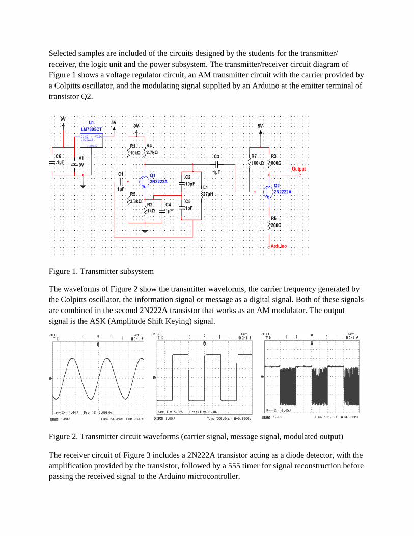
Project Description
A radio-controlled race car project was selected for the semester-long project. The project was
divided into four distinguishable subsystems, 1) remote control, 2) radio transmitter/receiver, 3)
logic control unit, based on an Arduino microcontroller, and 4) power subsystem. The
specifications for the four subsystems were made as flexible as possible. The remote control
could have been designed around a joystick or through the use of several buttons. The radio
transmitter/receiver could have been designed using AM, FM, ASK, or FSK technology and built
using LC oscillators and BJT transistors. Students were free to decide on the frequency of the
carrier and the type of modulation (analog or digital). Except for the Arduino microcontroller,
the use of microchips was restricted and only such analog components as diodes, Zener diodes,
bipolar junction transistors and MOSFETs were allowed. The power subsystem required a 9–18
volts DC to AC conversion and rectification.
The semester-long electronics project was scheduled as follows:
First week:
Initial presentation of the project to the students.
A block diagram and general specifications of the project given (Appendix 1)
Students were divided in groups of four to five.
First task:
o To identify the problem, what is the desired outcome;
o To state the basic objective or goal;
o To identify what is known about the problem, and what needs to be learned;
o To determine how the research and learning would be divided among the team
members.
Second week:
Homework/research assignment:
o To study AM, FM, ASK and FSK communication theory;
o To research how AM, FM, ASK and FSK transmitters and AM receivers work;
o To look for possible electronic car boards or commercial RC cars
Third week:
Students identified a cost effective solution for the chassis of the RC car
o Each team ordered for their car chassis the same commercial RC car;
o The electronics of each car was swapped out.
In the regular weekly lab session an experiment dealing with a diode detector circuit was
added.
Fourth week:
In the regular weekly lab session an experiment dealing with a Colpitts oscillator circuit
was added.
Fifth week:
In the regular weekly lab session an experiment dealing with an AM transmitter circuit
was added.
Sixth week to eleventh week
Students were given free access to work in the university’s electronic labs at their own
pace.
Twelfth week
All teams prepared a report of their findings and calculations.
Students presented power point presentations and demos of their projects
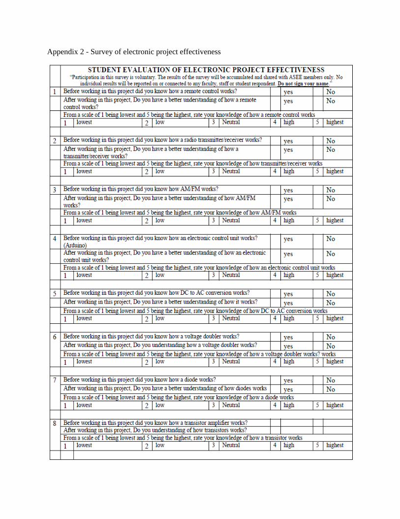
Students completed exit surveys of their projects (Appendix 2 through Appendix 6).
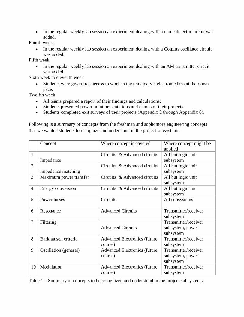
Following is a summary of concepts from the freshman and sophomore engineering concepts
that we wanted students to recognize and understand in the project subsystems.
Concept Where concept is covered Where concept might be
applied
1
Impedance
Circuits & Advanced circuits All but logic unit
subsystem
2
Impedance matching
Circuits & Advanced circuits All but logic unit
subsystem
3 Maximum power transfer Circuits & Advanced circuits All but logic unit
subsystem
4 Energy conversion Circuits & Advanced circuits All but logic unit
subsystem
5 Power losses Circuits All subsystems
6 Resonance Advanced Circuits Transmitter/receiver
subsystem
7 Filtering
Advanced Circuits
Transmitter/receiver
subsystem, power
subsystem
8 Barkhausen criteria
Advanced Electronics (future
course)
Transmitter/receiver
subsystem
9 Oscillation (general) Advanced Electronics (future
course)
Transmitter/receiver
subsystem, power
subsystem
10 Modulation Advanced Electronics (future
course)
Transmitter/receiver
subsystem
Table 1 – Summary of concepts to be recognized and understood in the project subsystems
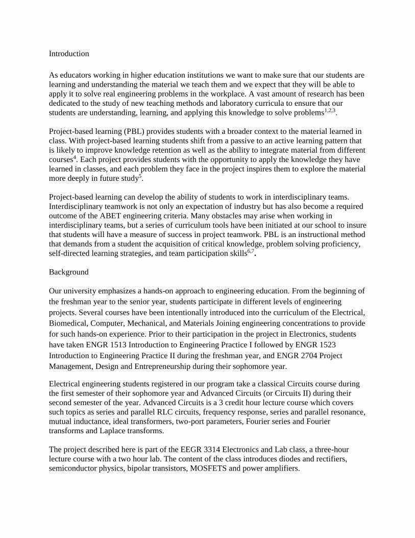
Selected samples are included of the circuits designed by the students for the transmitter/
receiver, the logic unit and the power subsystem. The transmitter/receiver circuit diagram of
Figure 1 shows a voltage regulator circuit, an AM transmitter circuit with the carrier provided by
a Colpitts oscillator, and the modulating signal supplied by an Arduino at the emitter terminal of
transistor Q2.
Figure 1. Transmitter subsystem
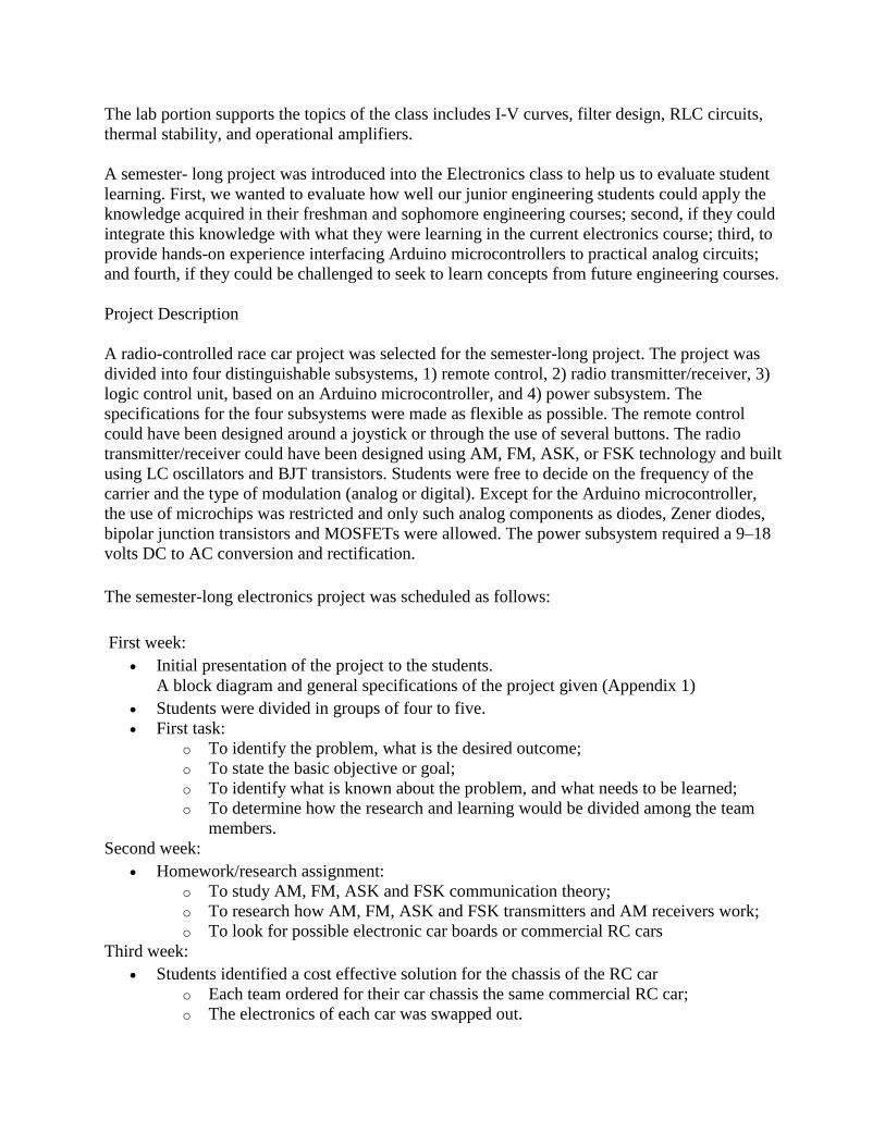
The waveforms of Figure 2 show the transmitter waveforms, the carrier frequency generated by
the Colpitts oscillator, the information signal or message as a digital signal. Both of these signals
are combined in the second 2N222A transistor that works as an AM modulator. The output
signal is the ASK (Amplitude Shift Keying) signal.
Figure 2. Transmitter circuit waveforms (carrier signal, message signal, modulated output)
The receiver circuit of Figure 3 includes a 2N222A transistor acting as a diode detector, with the
amplification provided by the transistor, followed by a 555 timer for signal reconstruction before
passing the received signal to the Arduino microcontroller.
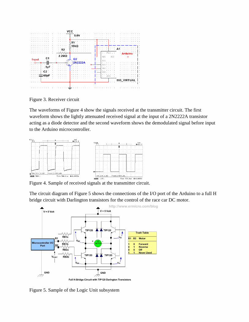
Figure 3. Receiver circuit
The waveforms of Figure 4 show the signals received at the transmitter circuit. The first
waveform shows the lightly attenuated received signal at the input of a 2N2222A transistor
acting as a diode detector and the second waveform shows the demodulated signal before input
to the Arduino microcontroller.
Figure 4. Sample of received signals at the transmitter circuit.
The circuit diagram of Figure 5 shows the connections of the I/O port of the Arduino to a full H
bridge circuit with Darlington transistors for the control of the race car DC motor.
Figure 5. Sample of the Logic Unit subsystem
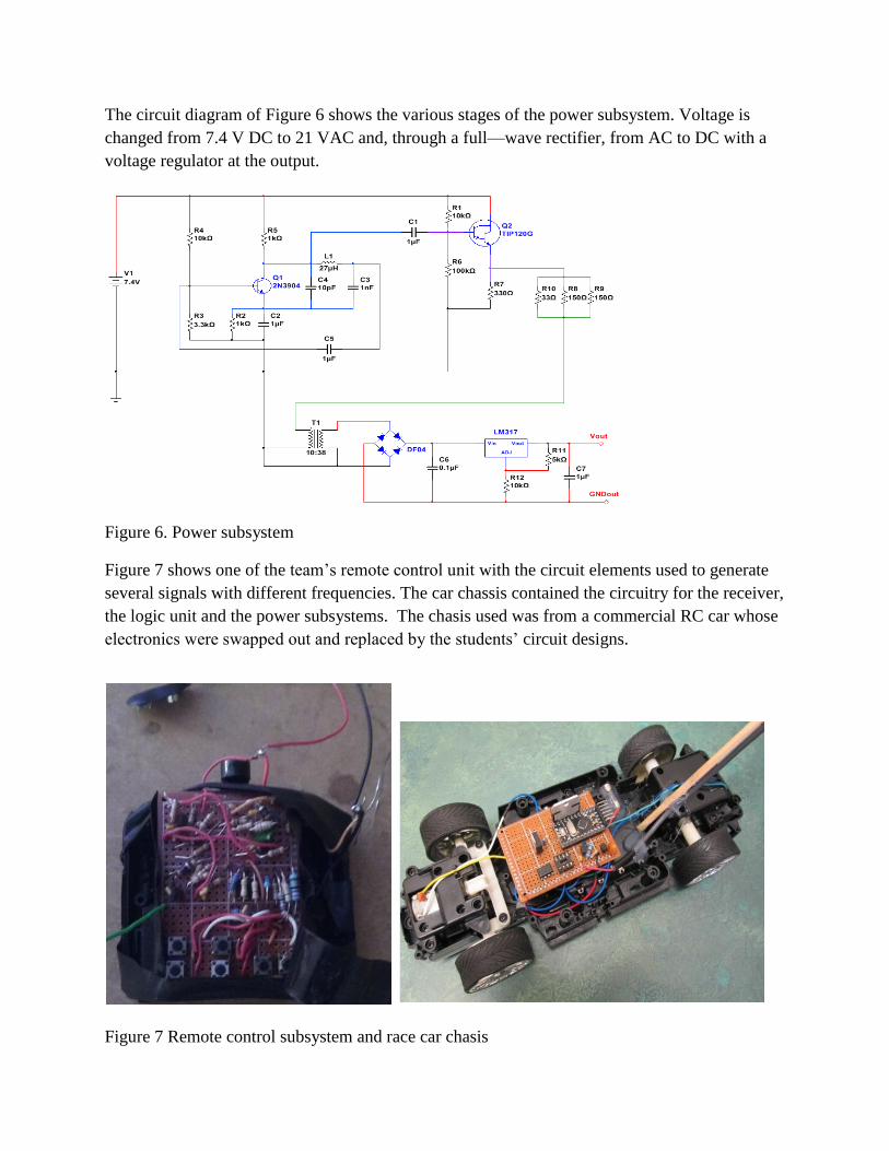
The circuit diagram of Figure 6 shows the various stages of the power subsystem. Voltage is
changed from 7.4 V DC to 21 VAC and, through a full—wave rectifier, from AC to DC with a
voltage regulator at the output.
Figure 6. Power subsystem
Figure 7 shows one of the team’s remote control unit with the circuit elements used to generate
several signals with different frequencies. The car chassis contained the circuitry for the receiver,
the logic unit and the power subsystems. The chasis used was from a commercial RC car whose
electronics were swapped out and replaced by the students’ circuit designs.
Figure 7 Remote control subsystem and race car chasis
Results
While five teams participated in this project, none of the teams were able to design the proper
antennas for the transmission and reception of the radio signals. Four weeks before the end of the
semester the requirement for the antennas was removed. Students were allowed to have direct
connection to their cars using a six to eight foot long wire. With the antenna requirement lifted,
two of the teams that were having problems with the generation of ASK signals changed their
modulation approach to a pulse width modulation. On the day of the presentation and
demonstration three teams presented completed projects, but only two cars were able to compete
for the test of speed and maneuverability.
Survey #1 was developed to evaluate whether the students were able to recognize, understand,
and apply their previous electrical engineering knowledge taught in EEGR2053 Electric Circuits
and EEGR2163 Advanced Circuits. Previous knowledge in concepts such as: impedance,
impedance matching, maximum power transfer, energy conversion and transformation, power
losses, resonance, and filtering. It also tried to evaluate whether the students were able to
recognize, understand, and apply electrical engineering concepts being taught or to be taught in
future engineering courses. Future engineering concepts like: oscillation, Barkhausen criterion,
and AM/FM frequency modulation.
The project was divided in four subsystems: remote control subsystem, transmitter/receiver
subsystem, logic unit Arduino subsystem and the power subsystem. For each subsystem two
questions were asked; the first question asked the student to recognize which concepts were
present or applied and the second question asked the student to rate on a scale of 1 to 5 his/her
understanding of the concept.
Results of survey one
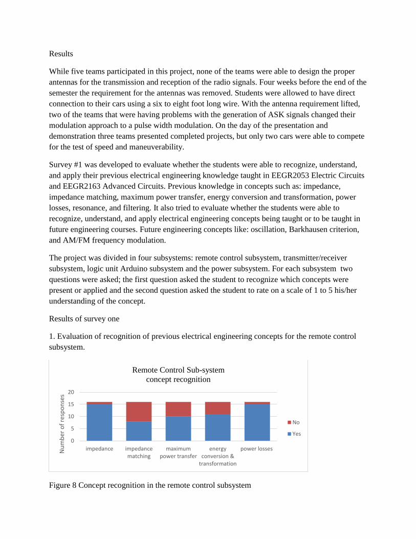
1. Evaluation of recognition of previous electrical engineering concepts for the remote control
subsystem.
Figure 8 Concept recognition in the remote control subsystem
0
5
10
15
20
impedance impedancematching
maximumpower transfer
energyconversion &
transformation
power lossesNu
mb
er o
f re
spo
nse
s
Remote Control Sub-system
concept recognition
No
Yes
Assuming the null hypothesis Ho to be: 100% of the students should be able to recognize all the
concepts” with ux=16, if the measured mean is uy= 11.8, then the one sample t test results in
t=3.0154, df=4 and the two tailed P=0.0393 is considered to be statistically significant.
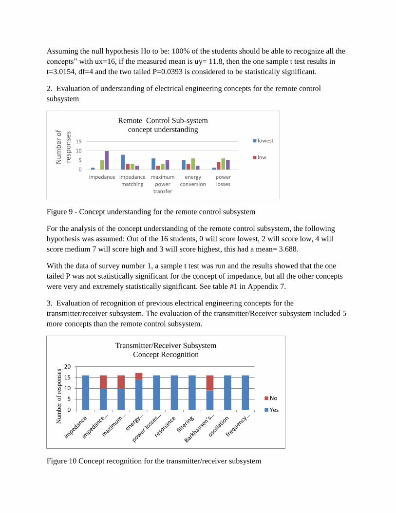
2. Evaluation of understanding of electrical engineering concepts for the remote control
subsystem
Figure 9 - Concept understanding for the remote control subsystem
For the analysis of the concept understanding of the remote control subsystem, the following
hypothesis was assumed: Out of the 16 students, 0 will score lowest, 2 will score low, 4 will
score medium 7 will score high and 3 will score highest, this had a mean= 3.688.
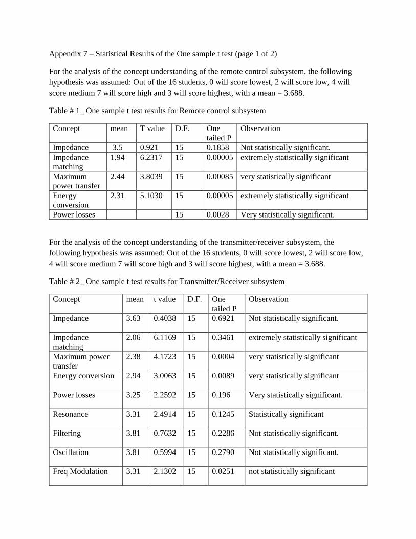
With the data of survey number 1, a sample t test was run and the results showed that the one
tailed P was not statistically significant for the concept of impedance, but all the other concepts
were very and extremely statistically significant. See table #1 in Appendix 7.
3. Evaluation of recognition of previous electrical engineering concepts for the
transmitter/receiver subsystem. The evaluation of the transmitter/Receiver subsystem included 5
more concepts than the remote control subsystem.
Figure 10 Concept recognition for the transmitter/receiver subsystem
0
5
10
15
impedance impedancematching
maximumpower
transfer
energyconversion
powerlosses
Nu
mb
er o
f re
spo
nse
s
Remote Control Sub-system
concept understanding
lowest
low
0
5
10
15
20
Num
ber
of
resp
onse
s
Transmitter/Receiver Subsystem
Concept Recognition
No
Yes
Assuming the null hypothesis Ho to be: 100% of the students should be able to recognize all the
concepts” with a mean =16. Running the one sample t test resulted in a measured mean= 13.9 ,
with a t=2.2150, df=9 and the one tailed P=0.0270, which is considered to be no statistically
significant.
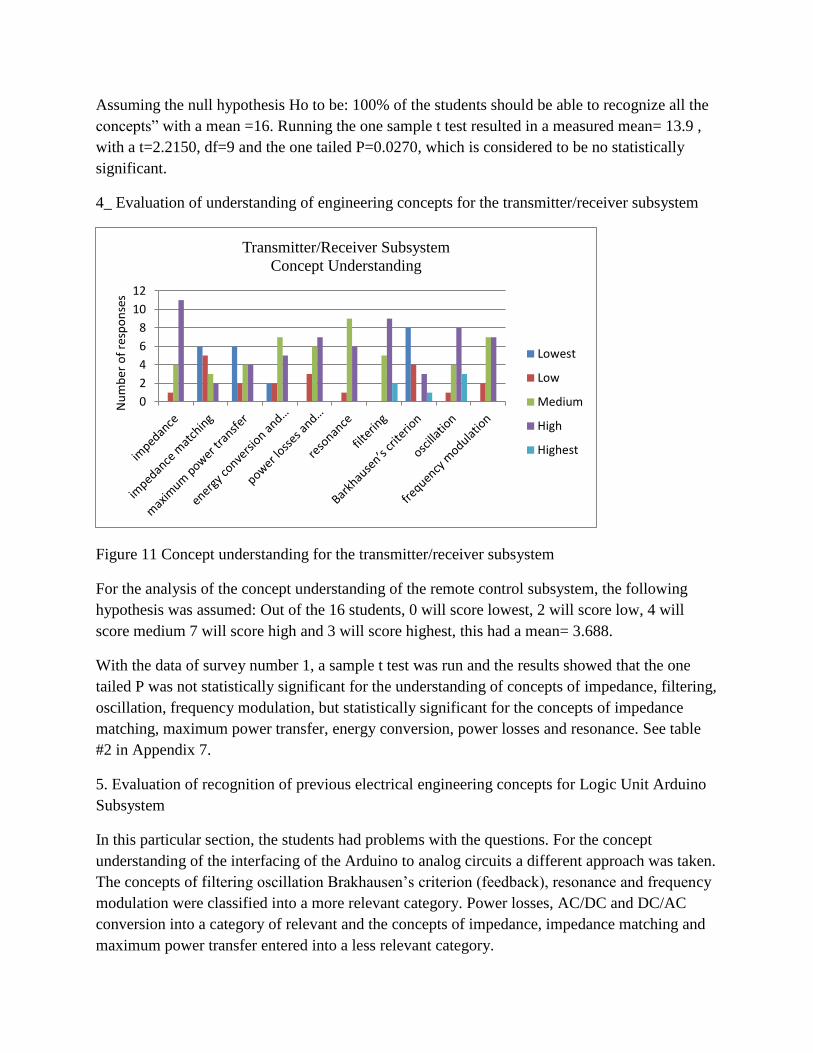
4_ Evaluation of understanding of engineering concepts for the transmitter/receiver subsystem
Figure 11 Concept understanding for the transmitter/receiver subsystem
For the analysis of the concept understanding of the remote control subsystem, the following
hypothesis was assumed: Out of the 16 students, 0 will score lowest, 2 will score low, 4 will
score medium 7 will score high and 3 will score highest, this had a mean= 3.688.
With the data of survey number 1, a sample t test was run and the results showed that the one
tailed P was not statistically significant for the understanding of concepts of impedance, filtering,
oscillation, frequency modulation, but statistically significant for the concepts of impedance
matching, maximum power transfer, energy conversion, power losses and resonance. See table
#2 in Appendix 7.
5. Evaluation of recognition of previous electrical engineering concepts for Logic Unit Arduino
Subsystem
In this particular section, the students had problems with the questions. For the concept
understanding of the interfacing of the Arduino to analog circuits a different approach was taken.
The concepts of filtering oscillation Brakhausen’s criterion (feedback), resonance and frequency
modulation were classified into a more relevant category. Power losses, AC/DC and DC/AC
conversion into a category of relevant and the concepts of impedance, impedance matching and
maximum power transfer entered into a less relevant category.
0
2
4
6
8
10
12
Nu
mb
er o
f re
spo
nse
s
Transmitter/Receiver Subsystem
Concept Understanding
Lowest
Low
Medium
High
Highest
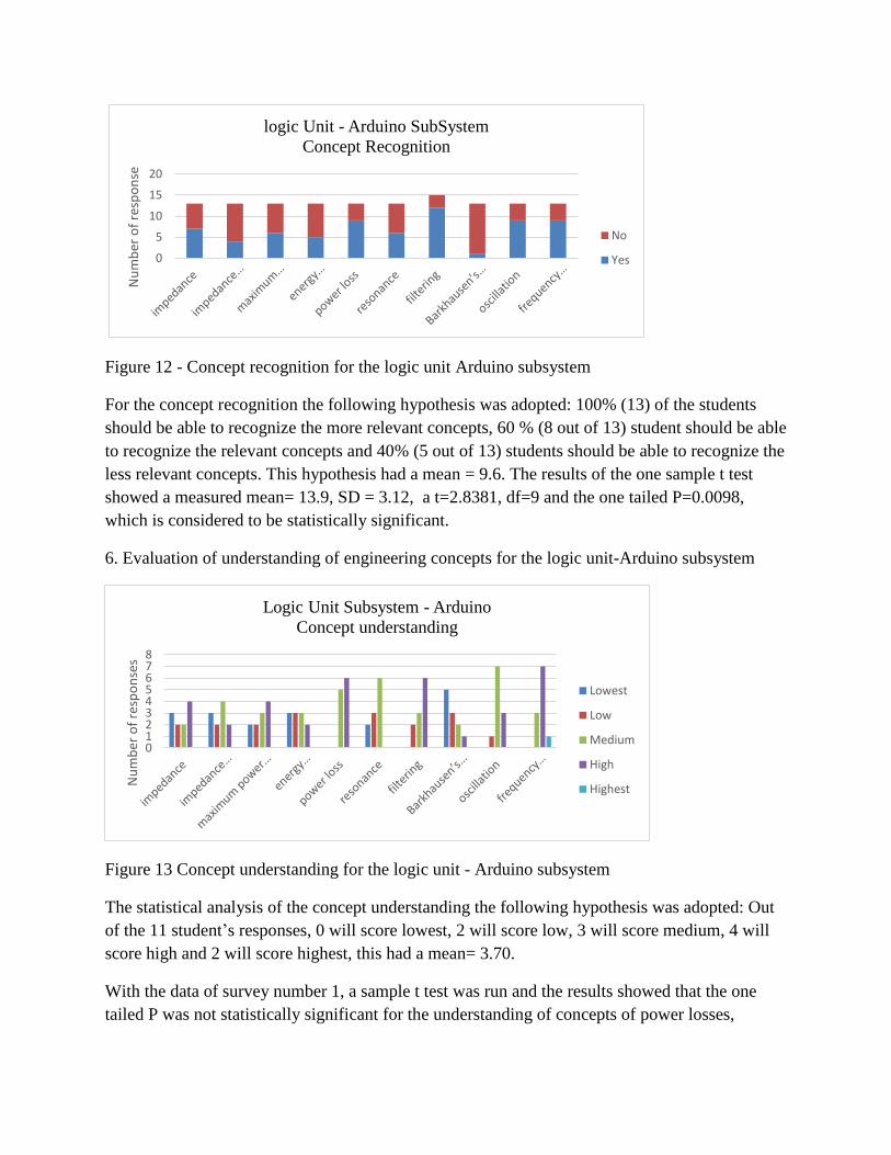
Figure 12 - Concept recognition for the logic unit Arduino subsystem
For the concept recognition the following hypothesis was adopted: 100% (13) of the students
should be able to recognize the more relevant concepts, 60 % (8 out of 13) student should be able
to recognize the relevant concepts and 40% (5 out of 13) students should be able to recognize the
less relevant concepts. This hypothesis had a mean = 9.6. The results of the one sample t test
showed a measured mean= 13.9, SD = 3.12, a t=2.8381, df=9 and the one tailed P=0.0098,
which is considered to be statistically significant.
6. Evaluation of understanding of engineering concepts for the logic unit-Arduino subsystem
Figure 13 Concept understanding for the logic unit - Arduino subsystem
The statistical analysis of the concept understanding the following hypothesis was adopted: Out
of the 11 student’s responses, 0 will score lowest, 2 will score low, 3 will score medium, 4 will
score high and 2 will score highest, this had a mean= 3.70.
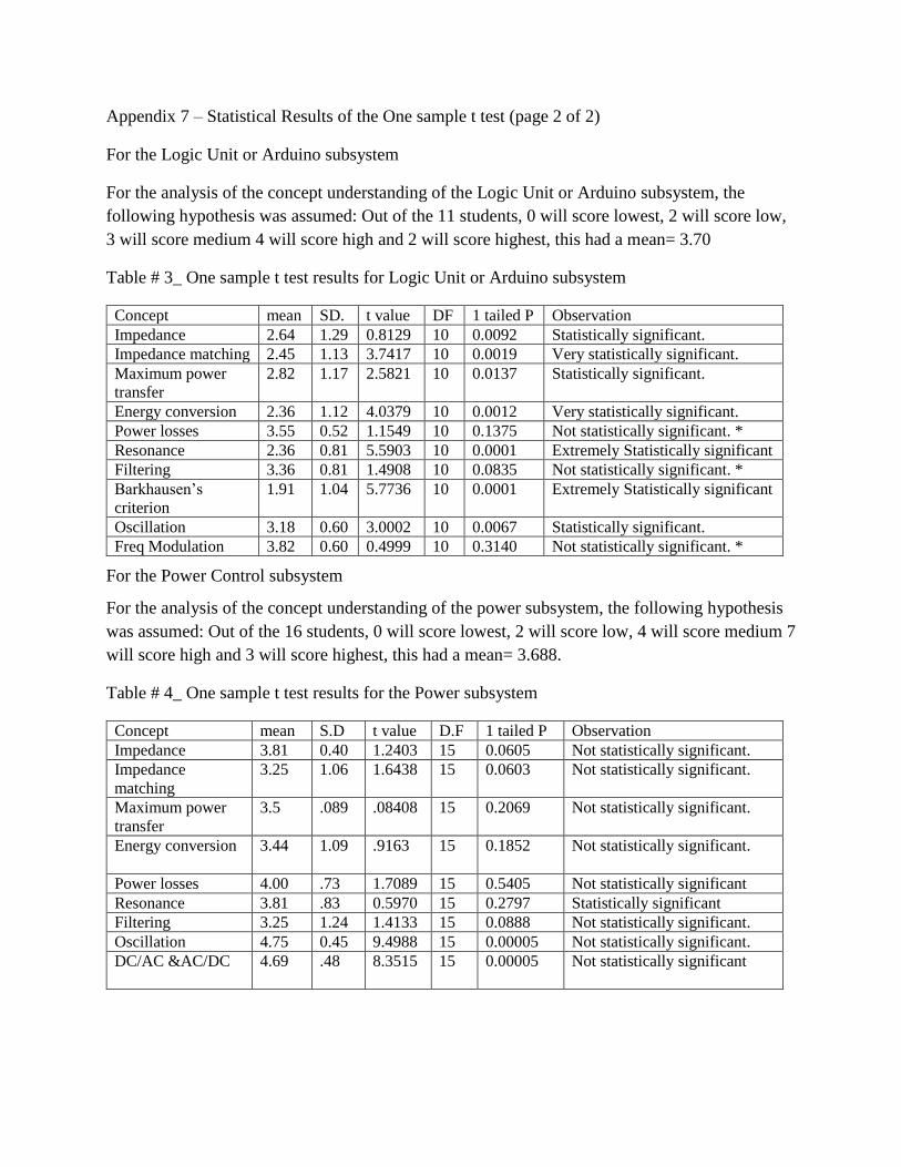
With the data of survey number 1, a sample t test was run and the results showed that the one
tailed P was not statistically significant for the understanding of concepts of power losses,
0
5
10
15
20
Nu
mb
er o
f re
spo
nse
logic Unit - Arduino SubSystem
Concept Recognition
No
Yes
012345678
Nu
mb
er o
f re
spo
nse
s
Logic Unit Subsystem - Arduino
Concept understanding
Lowest
Low
Medium
High
Highest
filtering and frequency modulation, but were statistically significant for all the other concepts.
See table #3 in Appendix 7.
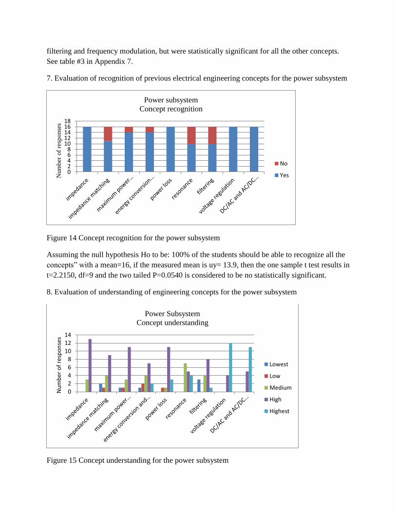
7. Evaluation of recognition of previous electrical engineering concepts for the power subsystem
Figure 14 Concept recognition for the power subsystem
Assuming the null hypothesis Ho to be: 100% of the students should be able to recognize all the
concepts” with a mean=16, if the measured mean is uy= 13.9, then the one sample t test results in
t=2.2150, df=9 and the two tailed P=0.0540 is considered to be no statistically significant.
8. Evaluation of understanding of engineering concepts for the power subsystem
Figure 15 Concept understanding for the power subsystem
02468
1012141618
Num
ber
of
resp
onse
s
Power subsystem
Concept recognition
No
Yes
0
2
4
6
8
10
12
14
Nu
mb
er o
f re
spo
nse
s
Power Subsystem
Concept understanding
Lowest
Low
Medium
High
Highest
For the analysis of the concept understanding of the power subsystem, the following hypothesis
was assumed: Out of the 16 students, 0 will score lowest, 2 will score low, 4 will score medium 7
will score high and 3 will score highest, this had a mean= 3.688.
With the data of survey number 1, a sample t test was run and the results showed that the one
tailed P was not statistically significant for the understanding of all the concepts included in the
power subsystem. See table #3 in Appendix 7.
Results of survey two
A second survey was prepared to evaluate the student’s knowledge and understanding of how the
different systems or components of the project. Each question in this survey was divided into
three parts. The first part asked what students knew about a system or element before the project,
the second part asked what they knew or understood about the system/element after completing
the project, and the third part asked the student to rate on a scale of 1 (low) to 5 (high) his/her
understanding of the system/element.
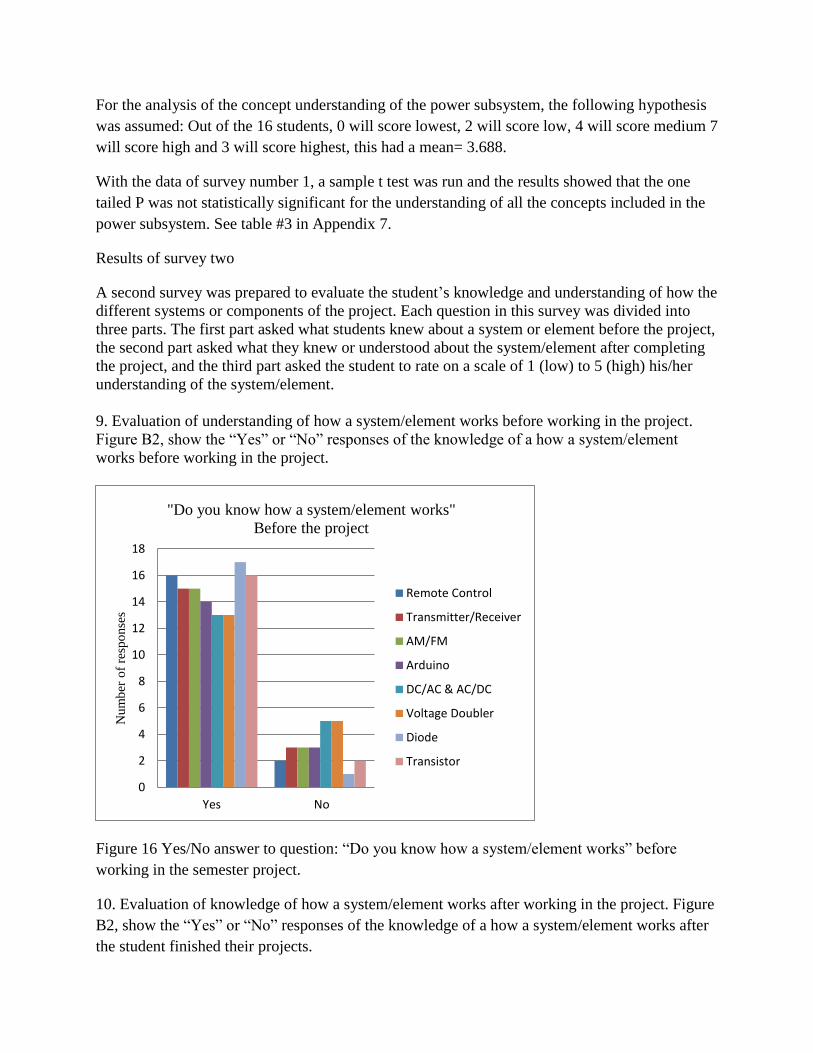
9. Evaluation of understanding of how a system/element works before working in the project.
Figure B2, show the “Yes” or “No” responses of the knowledge of a how a system/element
works before working in the project.
Figure 16 Yes/No answer to question: “Do you know how a system/element works” before
working in the semester project.
10. Evaluation of knowledge of how a system/element works after working in the project. Figure
B2, show the “Yes” or “No” responses of the knowledge of a how a system/element works after
the student finished their projects.
0
2
4
6
8
10
12
14
16
18
Yes No
Num
ber
of
resp
onse
s
"Do you know how a system/element works"
Before the project
Remote Control
Transmitter/Receiver
AM/FM
Arduino
DC/AC & AC/DC
Voltage Doubler
Diode
Transistor
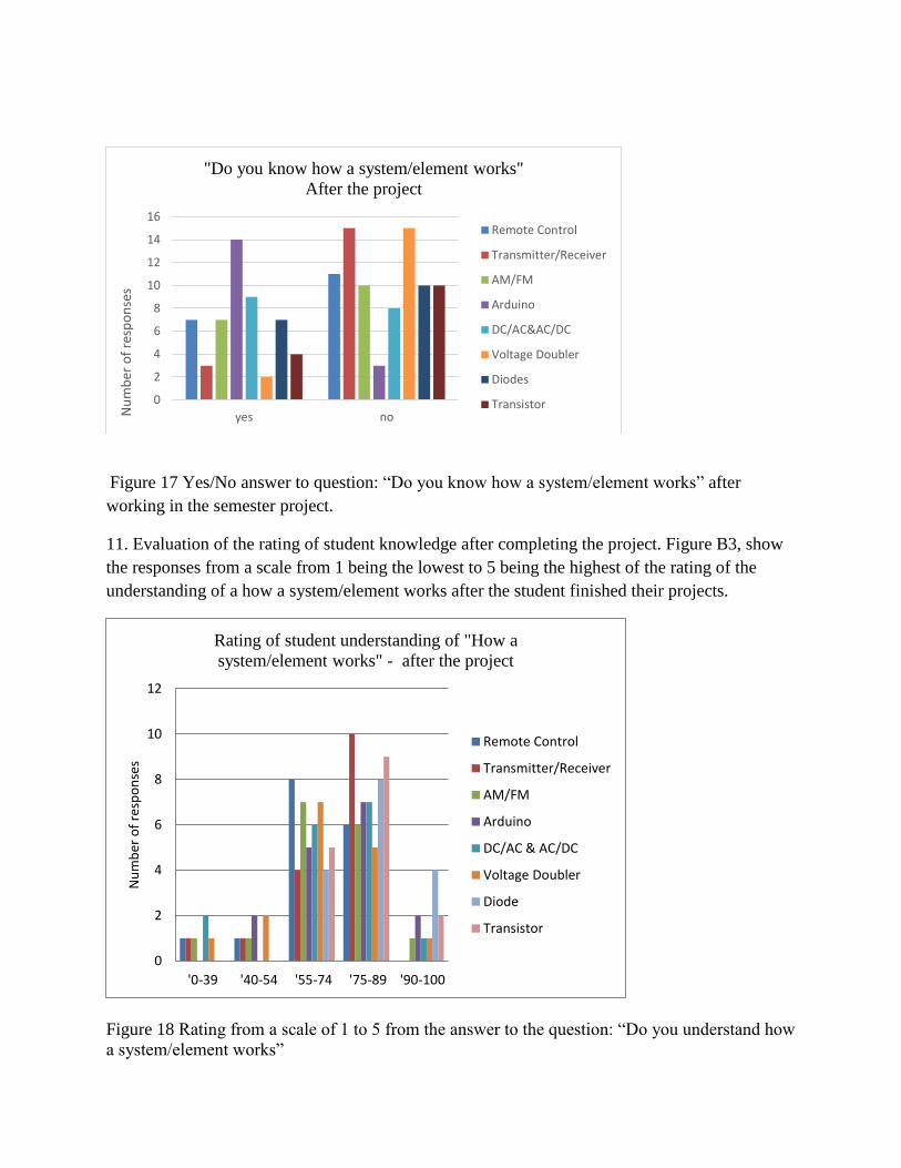
Figure 17 Yes/No answer to question: “Do you know how a system/element works” after
working in the semester project.
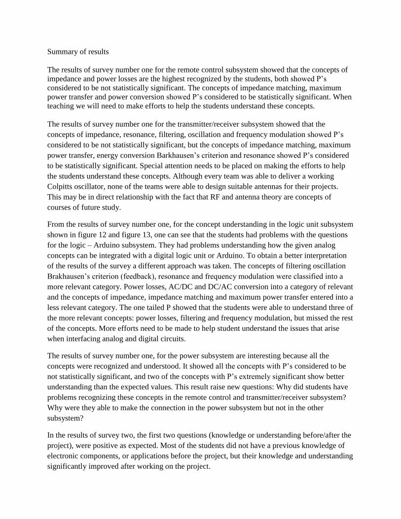
11. Evaluation of the rating of student knowledge after completing the project. Figure B3, show
the responses from a scale from 1 being the lowest to 5 being the highest of the rating of the
understanding of a how a system/element works after the student finished their projects.
Figure 18 Rating from a scale of 1 to 5 from the answer to the question: “Do you understand how
a system/element works”
0
2
4
6
8
10
12
14
16
yes noNu
mb
er o
f re
spo
nse
s
"Do you know how a system/element works"
After the project
Remote Control
Transmitter/Receiver
AM/FM
Arduino
DC/AC&AC/DC
Voltage Doubler
Diodes
Transistor
0
2
4
6
8
10
12
'0-39 '40-54 '55-74 '75-89 '90-100
Nu
mb
er o
f re
spo
nse
s
Rating of student understanding of "How a
system/element works" - after the project
Remote Control
Transmitter/Receiver
AM/FM
Arduino
DC/AC & AC/DC
Voltage Doubler
Diode
Transistor
Summary of results
The results of survey number one for the remote control subsystem showed that the concepts of
impedance and power losses are the highest recognized by the students, both showed P’s
considered to be not statistically significant. The concepts of impedance matching, maximum
power transfer and power conversion showed P’s considered to be statistically significant. When
teaching we will need to make efforts to help the students understand these concepts.
The results of survey number one for the transmitter/receiver subsystem showed that the
concepts of impedance, resonance, filtering, oscillation and frequency modulation showed P’s
considered to be not statistically significant, but the concepts of impedance matching, maximum
power transfer, energy conversion Barkhausen’s criterion and resonance showed P’s considered
to be statistically significant. Special attention needs to be placed on making the efforts to help
the students understand these concepts. Although every team was able to deliver a working
Colpitts oscillator, none of the teams were able to design suitable antennas for their projects.
This may be in direct relationship with the fact that RF and antenna theory are concepts of
courses of future study.
From the results of survey number one, for the concept understanding in the logic unit subsystem
shown in figure 12 and figure 13, one can see that the students had problems with the questions
for the logic – Arduino subsystem. They had problems understanding how the given analog
concepts can be integrated with a digital logic unit or Arduino. To obtain a better interpretation
of the results of the survey a different approach was taken. The concepts of filtering oscillation
Brakhausen’s criterion (feedback), resonance and frequency modulation were classified into a
more relevant category. Power losses, AC/DC and DC/AC conversion into a category of relevant
and the concepts of impedance, impedance matching and maximum power transfer entered into a
less relevant category. The one tailed P showed that the students were able to understand three of
the more relevant concepts: power losses, filtering and frequency modulation, but missed the rest
of the concepts. More efforts need to be made to help student understand the issues that arise
when interfacing analog and digital circuits.
The results of survey number one, for the power subsystem are interesting because all the
concepts were recognized and understood. It showed all the concepts with P’s considered to be
not statistically significant, and two of the concepts with P’s extremely significant show better
understanding than the expected values. This result raise new questions: Why did students have
problems recognizing these concepts in the remote control and transmitter/receiver subsystem?
Why were they able to make the connection in the power subsystem but not in the other
subsystem?
In the results of survey two, the first two questions (knowledge or understanding before/after the
project), were positive as expected. Most of the students did not have a previous knowledge of
electronic components, or applications before the project, but their knowledge and understanding
significantly improved after working on the project.
Conclusions
A radio-controlled race ca project was included in the first electronics lab for our EE students.
Results showed that not all concepts from earlier courses were recognized and applied. These
results point to a need for finding new ways of teaching that will help the student recognize,
understand and apply the engineering concepts learned from the freshman to the senior year. The
results are not conclusive, since these are the results of the first year of the project. To obtain
more consistent data, the principal investigator plans to include similar projects in his electronics
class for the following two years. The surveys will be improved to include questions that will
intentionally focus on the concepts with weakest understanding. The results of this project may
lead other disciplines in the school of engineering to develop their own projects to help them
determine if their students are able to recognize, understand and apply the engineering concepts
taught in their fields.
Bibliography
1Barrington L. and Duffy J. “Maximizing Benefits of Service-Learning in Engineering,”
Proceedings of the 2010 American Society for Engineering Education Annual Conference and
Exposition, June 20 - 23, 2010 Louisville, Kentucky.
2Dumbo, Myron, Motivation and Learning Strategies for College Success, Mahwah, N.J.,
Lawrence Erlbaum Associates, 2000, p.42.
3Hadim, H.A and Esche S.K., “Enhancing the Engineering Curriculum Through Project-Based
Learning,” Proceedings of the 32nd ASEE/IEEE frontiers in Education Conference, November 6-
9, 2002, Boston, Ma. F3F1-6.
4Mustafa, M., & De La Cruz, A., & Yousuf, A. (2010, June), “Project Based Learning” 2010
Annual Conference & Exposition, Louisville, Kentucky. https://peer.asee.org/16081
5Zhang, H., “Flying a Blimp- A Case Study of Project-Based Hands-on Engineering Education,”
Proceedings of the 2002 American Society for Engineering Education Annual Conference and
Exposition.
6Northern J. and Fuller, J., “Project-Based Learning for a Digital Circuits Design Sequence at
HBCUS”, Proceedings of the 2007 American Society for Engineering Education Annual
Conference and Exposition, June 24-27, 2007, Honolulu, Hawaii.
7Leiffer, P.R., Graff R.W. and Gonzalez R.V., “Five Curriculum Tools to Enhance
Interdisciplinary Teamwork,” Proceedings of the 2005 American Society for Engineering
Education Annual Conference and Exposition.
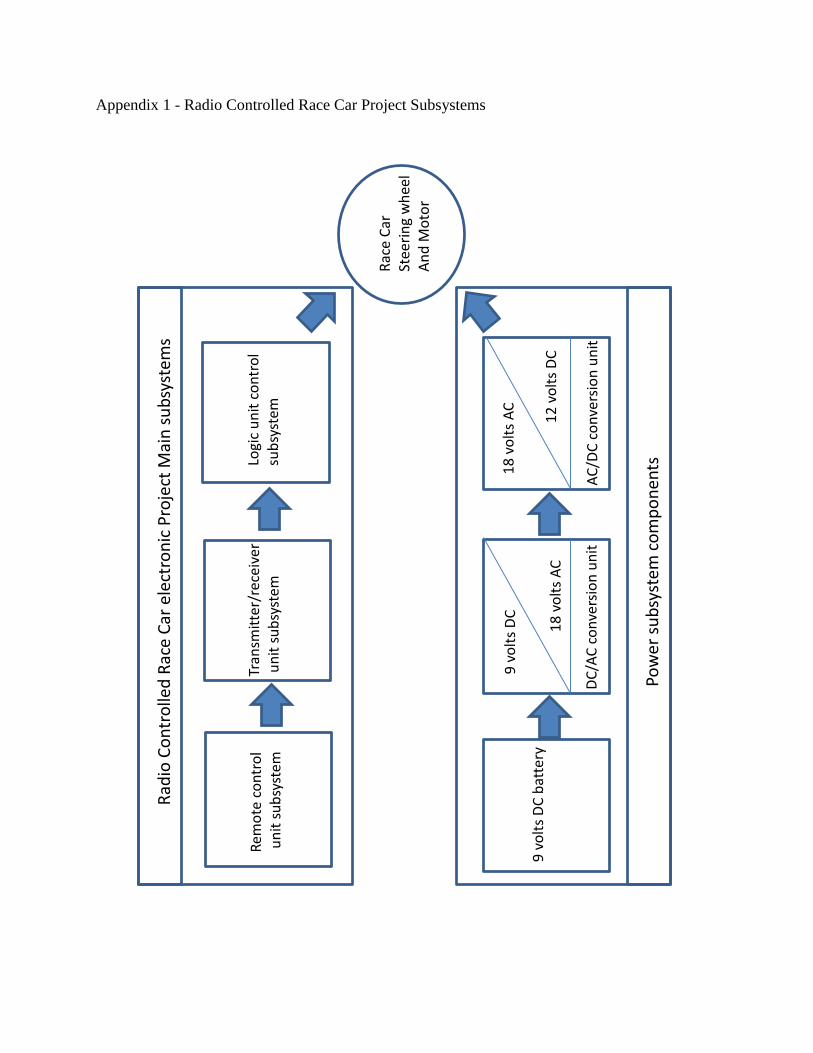
Appendix 1 - Radio Controlled Race Car Project Subsystems
Rad
io C
on
tro
lled
Rac
e C
ar e
lect
ron
ic P
roje
ct M
ain
su
bsy
stem
s
Pow
er s
ub
syst
em c
om
po
nen
ts
Rem
ote
co
ntr
ol
un
it s
ub
syst
em
Tran
smit
ter/
rece
iver
un
it s
ub
syst
em
Logi
c u
nit
co
ntr
ol
sub
syst
em
Rac
e C
ar
Stee
rin
g w
hee
l A
nd
Mo
tor
9 v
olt
s D
C b
atte
ry
9 v
olt
s D
C
18
vo
lts
AC
DC
/AC
co
nve
rsio
n u
nit
18
vo
lts
AC
12
vo
lts
DC
AC
/DC
co
nve
rsio
n u
nit
Appendix 2 - Survey of electronic project effectiveness
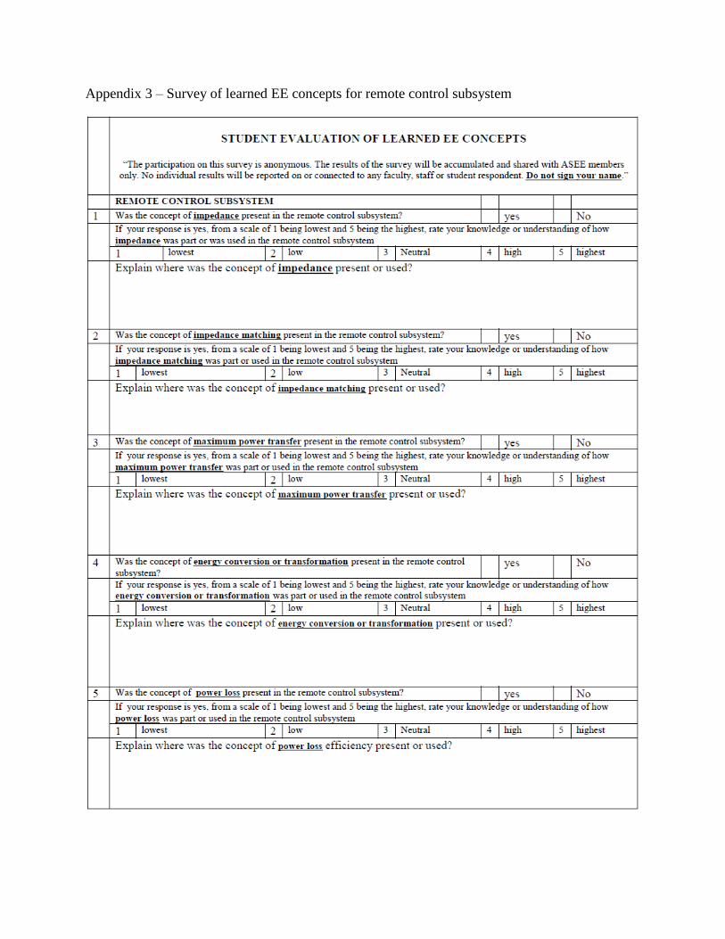
Appendix 3 – Survey of learned EE concepts for remote control subsystem
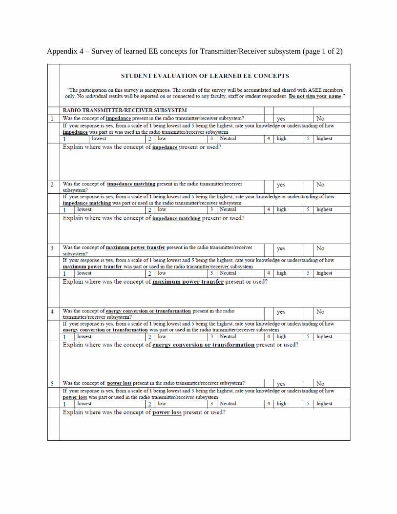
Appendix 4 – Survey of learned EE concepts for Transmitter/Receiver subsystem (page 1 of 2)
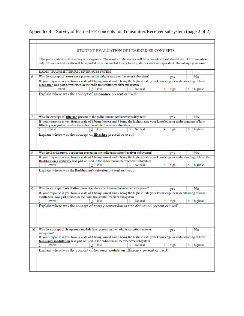
Appendix 4 – Survey of learned EE concepts for Transmitter/Receiver subsystem (page 2 of 2)
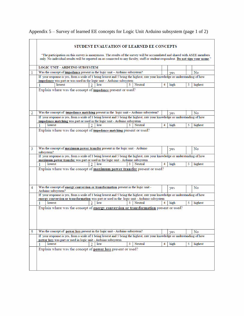
Appendix 5 – Survey of learned EE concepts for Logic Unit Arduino subsystem (page 1 of 2)
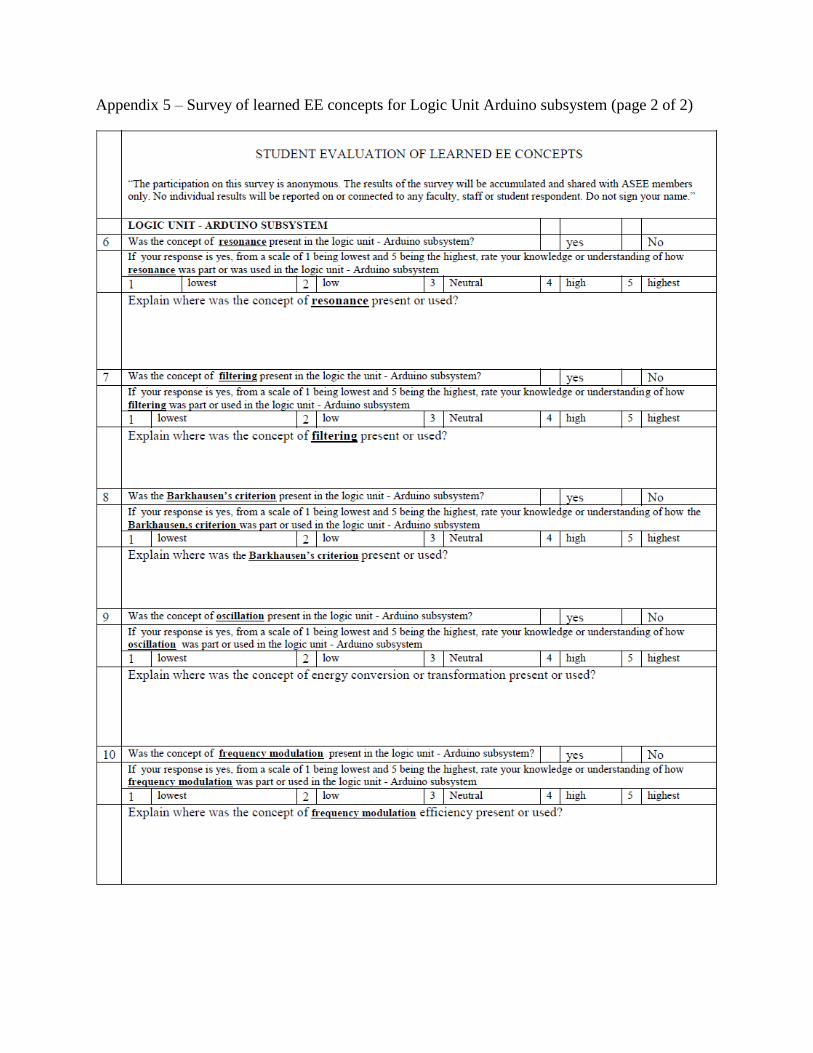
Appendix 5 – Survey of learned EE concepts for Logic Unit Arduino subsystem (page 2 of 2)
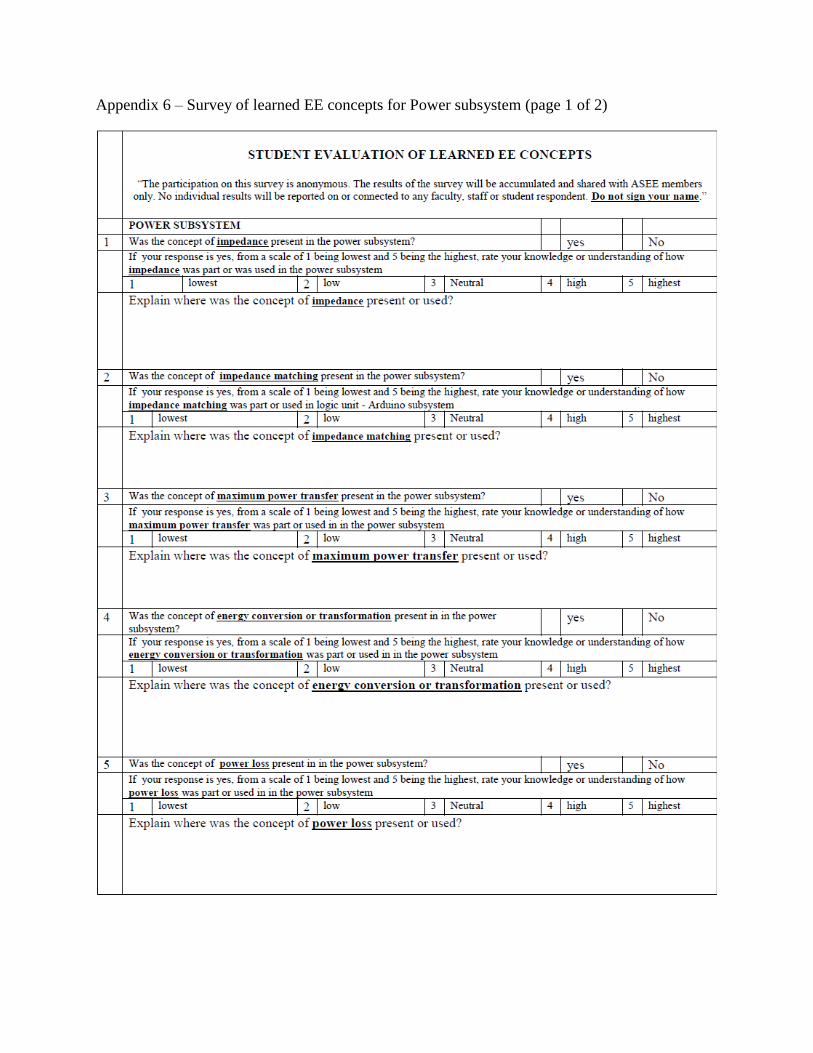
Appendix 6 – Survey of learned EE concepts for Power subsystem (page 1 of 2)
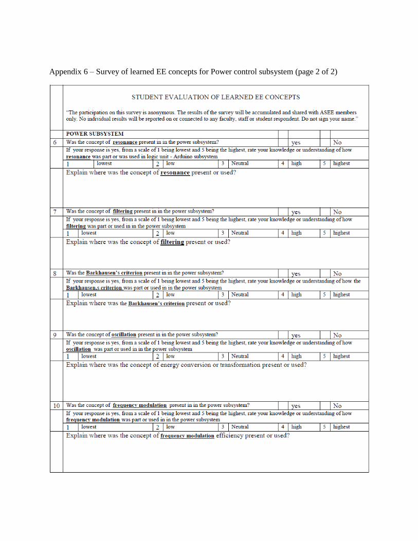
Appendix 6 – Survey of learned EE concepts for Power control subsystem (page 2 of 2)
Appendix 7 – Statistical Results of the One sample t test (page 1 of 2)
For the analysis of the concept understanding of the remote control subsystem, the following
hypothesis was assumed: Out of the 16 students, 0 will score lowest, 2 will score low, 4 will
score medium 7 will score high and 3 will score highest, with a mean = 3.688.
Table # 1_ One sample t test results for Remote control subsystem
Concept mean T value D.F. One
tailed P
Observation
Impedance 3.5 0.921 15 0.1858 Not statistically significant.
Impedance
matching
1.94 6.2317 15 0.00005 extremely statistically significant
Maximum
power transfer
2.44 3.8039 15 0.00085 very statistically significant
Energy
conversion
2.31 5.1030 15 0.00005 extremely statistically significant
Power losses 15 0.0028 Very statistically significant.
For the analysis of the concept understanding of the transmitter/receiver subsystem, the
following hypothesis was assumed: Out of the 16 students, 0 will score lowest, 2 will score low,
4 will score medium 7 will score high and 3 will score highest, with a mean = 3.688.
Table # 2_ One sample t test results for Transmitter/Receiver subsystem
Concept mean t value D.F. One
tailed P
Observation
Impedance 3.63 0.4038 15 0.6921 Not statistically significant.
Impedance
matching
2.06 6.1169 15 0.3461 extremely statistically significant
Maximum power
transfer
2.38 4.1723 15 0.0004 very statistically significant
Energy conversion 2.94 3.0063 15 0.0089 very statistically significant
Power losses 3.25 2.2592 15 0.196 Very statistically significant.
Resonance 3.31 2.4914 15 0.1245 Statistically significant
Filtering 3.81 0.7632 15 0.2286 Not statistically significant.
Oscillation 3.81 0.5994 15 0.2790 Not statistically significant.
Freq Modulation 3.31 2.1302 15 0.0251 not statistically significant
Appendix 7 – Statistical Results of the One sample t test (page 2 of 2)
For the Logic Unit or Arduino subsystem
For the analysis of the concept understanding of the Logic Unit or Arduino subsystem, the
following hypothesis was assumed: Out of the 11 students, 0 will score lowest, 2 will score low,
3 will score medium 4 will score high and 2 will score highest, this had a mean= 3.70
Table # 3_ One sample t test results for Logic Unit or Arduino subsystem
Concept mean SD. t value DF 1 tailed P Observation
Impedance 2.64 1.29 0.8129 10 0.0092 Statistically significant.
Impedance matching 2.45 1.13 3.7417 10 0.0019 Very statistically significant.
Maximum power
transfer
2.82 1.17 2.5821 10 0.0137 Statistically significant.
Energy conversion 2.36 1.12 4.0379 10 0.0012 Very statistically significant.
Power losses 3.55 0.52 1.1549 10 0.1375 Not statistically significant. *
Resonance 2.36 0.81 5.5903 10 0.0001 Extremely Statistically significant
Filtering 3.36 0.81 1.4908 10 0.0835 Not statistically significant. *
Barkhausen’s
criterion
1.91 1.04 5.7736 10 0.0001 Extremely Statistically significant
Oscillation 3.18 0.60 3.0002 10 0.0067 Statistically significant.
Freq Modulation 3.82 0.60 0.4999 10 0.3140 Not statistically significant. *
For the Power Control subsystem
For the analysis of the concept understanding of the power subsystem, the following hypothesis
was assumed: Out of the 16 students, 0 will score lowest, 2 will score low, 4 will score medium 7
will score high and 3 will score highest, this had a mean= 3.688.
Table # 4_ One sample t test results for the Power subsystem
Concept mean S.D t value D.F 1 tailed P Observation
Impedance 3.81 0.40 1.2403 15 0.0605 Not statistically significant.
Impedance
matching
3.25 1.06 1.6438 15 0.0603 Not statistically significant.
Maximum power
transfer
3.5 .089 .08408 15 0.2069 Not statistically significant.
Energy conversion 3.44 1.09 .9163 15 0.1852 Not statistically significant.
Power losses 4.00 .73 1.7089 15 0.5405 Not statistically significant
Resonance 3.81 .83 0.5970 15 0.2797 Statistically significant
Filtering 3.25 1.24 1.4133 15 0.0888 Not statistically significant.
Oscillation 4.75 0.45 9.4988 15 0.00005 Not statistically significant.
DC/AC &AC/DC 4.69 .48 8.3515 15 0.00005 Not statistically significant