Embed Size (px)
Citation preview
F. MARINO, A. DISTANTE, P.L. MAZZEO and E. STELLA: A Real Time Visual Inspection System...
-1-
A Real Time Visual Inspection System for Railway Maintenance:
Automatic Hexagonal Headed Bolts Detection
Francescomaria Marino, Arcangelo Distante, Pier Luigi Mazzeo and Ettore Stella#
Abstract—Rail inspection is a very important task in railway maintenance and it is periodically needed for
preventing dangerous situations. Inspection is operated manually by trained human operator walking along the track
searching for visual anomalies. This monitoring is unacceptable for slowness and lack of objectivity, because the
results are related to the ability of the observer to recognize critical situations.
The paper presents VISyR, a patent pending real time V isual Inspection System for Railway maintenance, and
describes how presence/absence of the fastening bolts that fix the rails to the sleepers is automatically detected.
VISyR acquires images from a digital line scan camera. Data are simultaneously preprocessed according to two
Discrete Wavelet Transforms, and then provided to two Multi Layer Perceptron Neural Classifiers (MLPNCs). The
“cross validation” of these MLPNCs avoids (practically-at-all) false positive, and reveals the presence/absence of
the fastening bolts with an accuracy of 99.6% in detecting visible bolts and of 95% in detecting missing bolts. A
FPGA -based architecture performs these tasks in 8.09 µs, allowing an on-the-fly analysis of a video sequence
acquired up at 200 km/h.
Index Terms — Neural network applications, Rail transportation maintenance, Machine vision, Object recognition,
Pattern recognition, Real-time systems .
I. INTRODUCTION
The railway maintenance is a particular application context in which the periodical surface
inspection of the rolling plane is required in order to prevent any dangerous situation. Usually,
• F. Marino is with the Dipartimento di Elettrotecnica ed Elettronica (DEE), Facoltà di Ingegneria, Politecnico di Bari; via Re David 200;
70125 Bari, ITALY. Fax: (+39) 080.5963410; Phone: (+39) 080.5963710; E-Mail: [email protected]
• A. Distante, P.L. Mazzeo and E. Stella are with the Istituto di Studi sui Sistemi Intelligenti per l'Automazione (ISSIA) CNR; via G. Amendola 122/D-O; 70126 Bari, ITALY. Fax: (+39) 080.5929460; Phone: (+39) 080.5929429; E-Mail: {distante, mazzeo, stella}@ba.issia.cnr.it. This work has been partially supported by the Italian Ministry of University and Research (MIUR), research project PON “RAILSAFE”.
F. MARINO, A. DISTANTE, P.L. MAZZEO and E. STELLA: A Real Time Visual Inspection System...
-2-
this task is performed by trained personnel that, periodically, walks along the railway network
searching for visual anomalies. Actually, this manual inspection is slow, laborious and
potentially hazardous, and the results are strictly dependent on the capability of the observer to
detect possible anomalies and to recognize critical situations.
With the growing of the high-speed railway traffic, companies over the world are interested to
develop automatic inspection systems which are able to detect rail defects, sleepers’ anomalies,
as well as missing fastening elements. These systems could increase the ability in the detection of
defects and reduce the inspection time in order to guarantee more frequently the maintenance of
the railway network.
In this work we introduce VISyR, a patented [1] real time Visual Inspection System for
Railway maintanance that is able to detect missing fastening bolts and other rail defects. For sake
of conciseness, this paper deals only with the automatic bolts detection, while, hardware and
software architecture of a second block, devoted to reveal other kind of defects, are described in
[2].
Usually two kinds of fastening elements are used to secure the rail to the sleepers: hexagonal-
headed bolts and hook bolts. They essentially differ by shape: the first one has a regular
hexagonal shape having random orientation, the second one has a more complex hook shape that
can be found oriented only in one direction.
In this paper the case of hexagonal headed bolts is discussed. As shown in our previous works
[3], [4] and shortly recalled, detection of this kind of bolt results more difficult than that of more
complex shapes (e.g., hook bolts) because of the similarity of the hexagonal bolts with the shape
of the stones that are on the background. Nevertheless, detection of hook bolts is also treated in
Section VII.E
F. MARINO, A. DISTANTE, P.L. MAZZEO and E. STELLA: A Real Time Visual Inspection System...
-3-
Even if some works have been performed, which deal with railway problems -such as track
profile measurement (e.g., [5]), obstruction detection (e.g., [6]), braking control (e.g., [7]), rail
defect recognition (e.g., [8], [9]), ballast reconstruction (e.g., [8]), switches status detection (e.g.,
[10]), control and activation of signals near stations (e.g., [11]), etc.- at the best of our
knowledge, in literature there are no references on the specific problem of fastening elements
recognition (except for our works [3], [4]). The only found approaches, are commercial vision
systems [8], which consider only fastening elements having regular geometrical shape (like
hexagonal bolts) and use geometrical approaches to pattern recognition to resolve the problem.
Moreover, these systems are strongly interactive. In fact, in order to reach the best performances,
they require a human operator for tuning any threshold. When a different fastening element is
considered, the tuning phase has to be re-executed.
Contrariwise, VISyR is completely automatic and needs no tuning phase. The human operator
has only the task of selecting images of the fastening elements to manage. No assumption about
the shape of the fastening elements is required, since the method is suitable for both geometric
and generic shapes.
The processing core of VISyR is basically composed by a Bolts Detection Block (BDB) and
by a Rail Analyser Block (RAB) [2]. In order to avoid (in practice, completely) false positive
detection, BDB intersects the results of two different classifiers. Therefore, it is composed by
two 2-D Discrete Wavelet Transforms (DWTs), [12]-[16] which significantly reduces the input
space dimension, and by two Multi Layer Perceptron Neural Classifiers (MLPNCs) that
recognize the hexagonal headed bolts on the sleepers. BDB gets an accuracy of 99.6% in
detecting visible bolts and of 95% in detecting missing bolts, moreover, because of its crossed
detecting strategy, reveals only 1 false positive over 2,250 lines of processed video sequence.
F. MARINO, A. DISTANTE, P.L. MAZZEO and E. STELLA: A Real Time Visual Inspection System...
-4-
A FPGA-based hardware implementation (performing BDB computations in 8.09 µs), in
cooperation with a simple -but efficient- prediction algorithm (which, exploiting the geometry of
the railways, extracts from the long video sequence few windows to be analysed) allow real time
performance, since a long sequence of images covering about 9 km has been inspected at an
average velocity of 152 km/h, with peaks of 201 km/h.
Moreover, because of the FPGA technology chosen for the development, VISyR is
characterized by a great versatility. For instance, detection of different kinds of bolts can be
performed simply by downloading onto the FPGA different neural weights (generated by a
proper training step) during the setup.
The paper is organized as follows.
In Section II, an overview of VISyR is presented. Section III introduces the developed
prediction algorithm. Section IV describes the 2-D DWT preprocessing. The Multi Layer
Perceptron Neural Classifier is illustrated in Section V. The implemented hardware architecture
is described in Section VI. Experimental results and computing performance are reported in
Section VII. Conclusive remarks and future perspectives are given in Section VIII.
II. SYSTEM OVERVIEW
VISyR acquires images of the rail by means of a DALSA PIRANHA 2 line scan camera [17]
having 1024 pixels of resolution (maximum line rate of 67 kLine/s) and using the Cameralink
protocol [18]. Furthermore, it is provided with a PC-CAMLINK frame grabber (Imaging
Technology CORECO) [19]. In order to reduce the effects of variable natural lighting conditions,
an appropriate illumination setup equipped with six OSRAM 41850 FL light sources has been
installed too. In this way the system is robust against changes in the natural illumination.
Moreover, in order to synchronize data acquisition, the line scan camera is triggered by the
F. MARINO, A. DISTANTE, P.L. MAZZEO and E. STELLA: A Real Time Visual Inspection System...
-5-
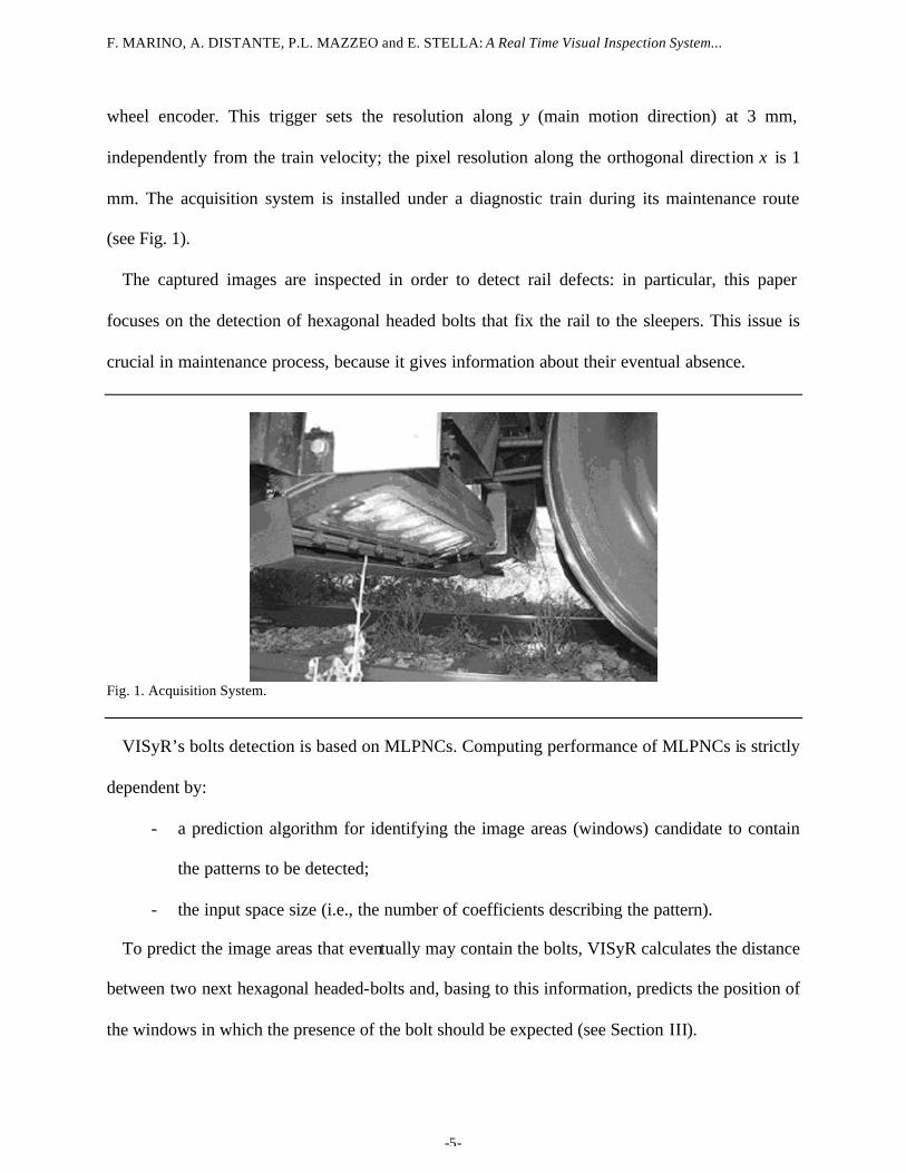
wheel encoder. This trigger sets the resolution along y (main motion direction) at 3 mm,
independently from the train velocity; the pixel resolution along the orthogonal direction x is 1
mm. The acquisition system is installed under a diagnostic train during its maintenance route
(see Fig. 1).
The captured images are inspected in order to detect rail defects: in particular, this paper
focuses on the detection of hexagonal headed bolts that fix the rail to the sleepers. This issue is
crucial in maintenance process, because it gives information about their eventual absence.
Fig. 1. Acquisition System.
VISyR’s bolts detection is based on MLPNCs. Computing performance of MLPNCs is strictly
dependent by:
- a prediction algorithm for identifying the image areas (windows) candidate to contain
the patterns to be detected;
- the input space size (i.e., the number of coefficients describing the pattern).
To predict the image areas that eventually may contain the bolts, VISyR calculates the distance
between two next hexagonal headed-bolts and, basing to this information, predicts the position of
the windows in which the presence of the bolt should be expected (see Section III).
F. MARINO, A. DISTANTE, P.L. MAZZEO and E. STELLA: A Real Time Visual Inspection System...
-6-
For reducing the input space size, VISyR uses a features extraction algorithm that is able to
preserve all the important information about input patterns in a small set of coefficients. This
algorithm is based on 2-D DWTs [12]-[16], since DWT concentrates the significant variations of
input patterns in a reduced number of coefficients (see Section IV). Specifically, both a compact
wavelet introduced by Daubechies [12], and the Haar DWT (also known as Haar Transform
[16]) are simultaneously used, since we have verified that, for our specific application, the
logical AND of these two approaches avoids -almost completely- the false positive detection (see
Section VII.B)
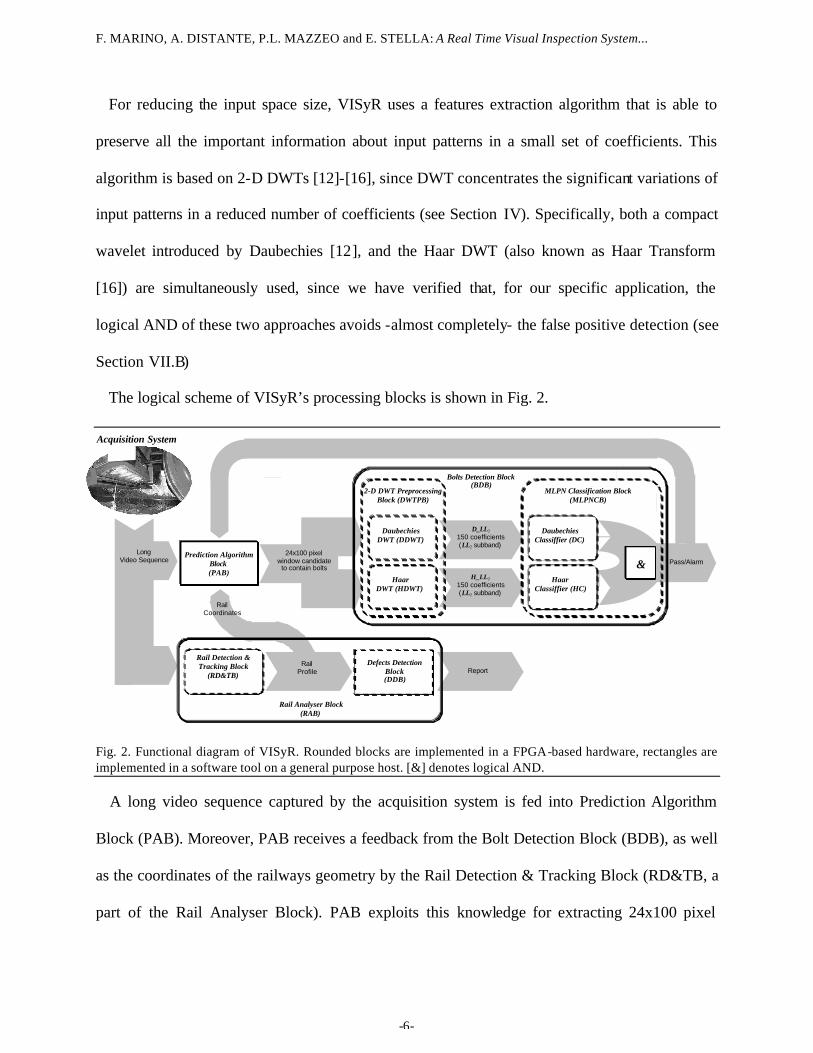
The logical scheme of VISyR’s processing blocks is shown in Fig. 2.
Rail Analyser Block(RAB)
HaarDWT (HDWT)
Bolts Detection Block(BDB)
Report
Prediction AlgorithmBlock(PAB)
Rail Detection &Tracking Block
(RD&TB)
Defects DetectionBlock(DDB)
Acquisition System
LongVideo Sequence
2-D DWT PreprocessingBlock (DWTPB)
DaubechiesDWT (DDWT)
MLPN Classification Block(MLPNCB)
D_LL2
150 coefficients(LL2 subband)
&Haar
Classiffier (HC)
DaubechiesClassiffier (DC)
24x100 pixelwindow candidate
to contain boltsPass/Alarm
H_LL2
150 coefficients(LL2 subband)
RailCoordinates
RailProfile
Fig. 2. Functional diagram of VISyR. Rounded blocks are implemented in a FPGA-based hardware, rectangles are implemented in a software tool on a general purpose host. [&] denotes logical AND.
A long video sequence captured by the acquisition system is fed into Prediction Algorithm
Block (PAB). Moreover, PAB receives a feedback from the Bolt Detection Block (BDB), as well
as the coordinates of the railways geometry by the Rail Detection & Tracking Block (RD&TB, a
part of the Rail Analyser Block). PAB exploits this knowledge for extracting 24x100 pixel
F. MARINO, A. DISTANTE, P.L. MAZZEO and E. STELLA: A Real Time Visual Inspection System...
-7-
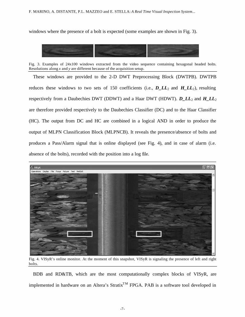
windows where the presence of a bolt is expected (some examples are shown in Fig. 3).
Fig. 3. Examples of 24x100 windows extracted from the video sequence containing hexagonal headed bolts. Resolutions along x and y are different because of the acquisition setup.
These windows are provided to the 2-D DWT Preprocessing Block (DWTPB). DWTPB
reduces these windows to two sets of 150 coefficients (i.e., D_LL2 and H_LL2), resulting
respectively from a Daubechies DWT (DDWT) and a Haar DWT (HDWT). D_LL2 and H_LL2
are therefore provided respectively to the Daubechies Classifier (DC) and to the Haar Classifier
(HC). The output from DC and HC are combined in a logical AND in order to produce the
output of MLPN Classification Block (MLPNCB). It reveals the presence/absence of bolts and
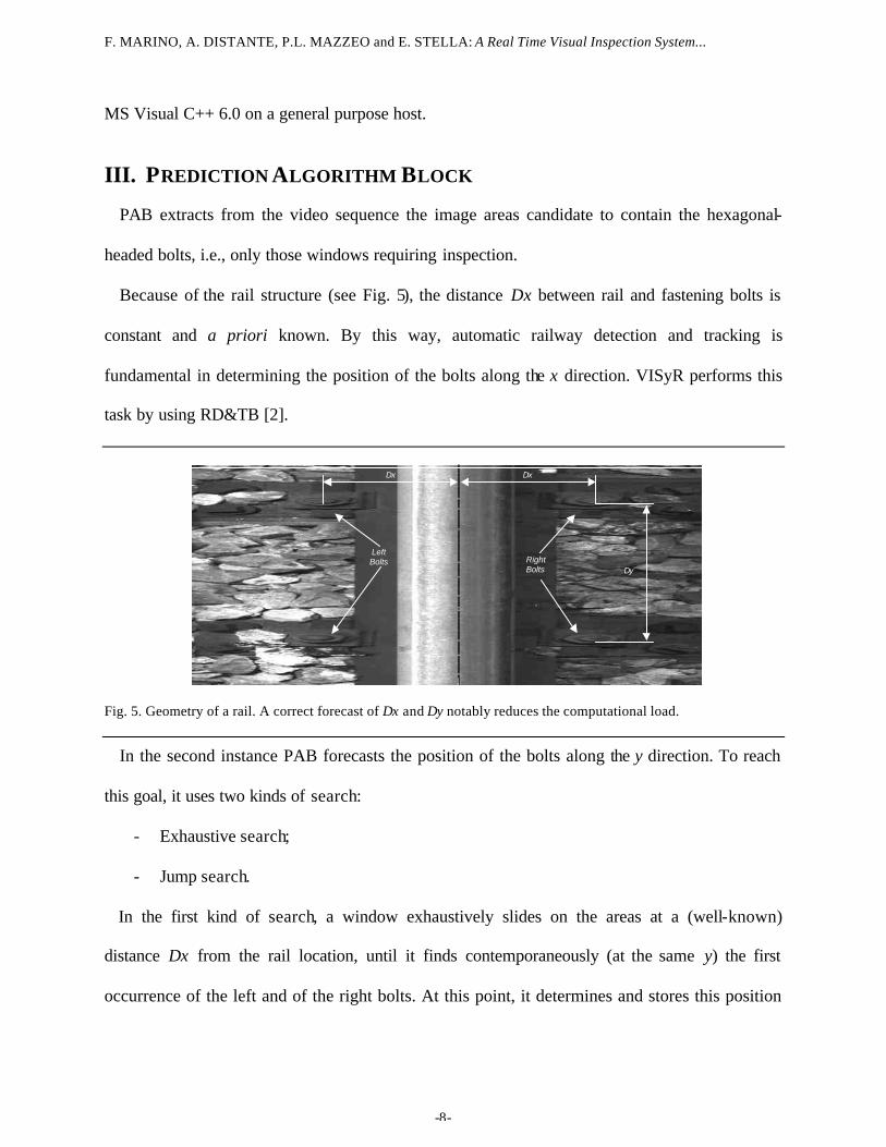
produces a Pass/Alarm signal that is online displayed (see Fig. 4), and in case of alarm (i.e.
absence of the bolts), recorded with the position into a log file.
Fig. 4. VISyR’s online monitor. At the moment of this snapshot, VISyR is signaling the presence of left and right bolts.
BDB and RD&TB, which are the most computationally complex blocks of VISyR, are
implemented in hardware on an Altera’s StratixTM FPGA. PAB is a software tool developed in
F. MARINO, A. DISTANTE, P.L. MAZZEO and E. STELLA: A Real Time Visual Inspection System...
-8-
MS Visual C++ 6.0 on a general purpose host.
III. PREDICTION ALGORITHM BLOCK
PAB extracts from the video sequence the image areas candidate to contain the hexagonal-
headed bolts, i.e., only those windows requiring inspection.
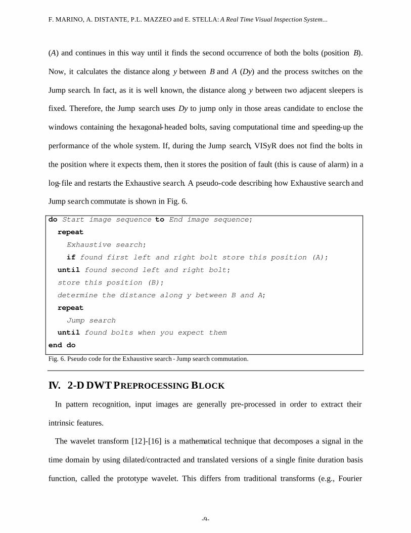
Because of the rail structure (see Fig. 5), the distance Dx between rail and fastening bolts is
constant and a priori known. By this way, automatic railway detection and tracking is
fundamental in determining the position of the bolts along the x direction. VISyR performs this
task by using RD&TB [2].
Dy
Dx Dx
Left Bolts Right
Bolts
Fig. 5. Geometry of a rail. A correct forecast of Dx and Dy notably reduces the computational load.
In the second instance PAB forecasts the position of the bolts along the y direction. To reach
this goal, it uses two kinds of search:
- Exhaustive search;
- Jump search.
In the first kind of search, a window exhaustively slides on the areas at a (well-known)
distance Dx from the rail location, until it finds contemporaneously (at the same y) the first
occurrence of the left and of the right bolts. At this point, it determines and stores this position
F. MARINO, A. DISTANTE, P.L. MAZZEO and E. STELLA: A Real Time Visual Inspection System...
-9-
(A) and continues in this way until it finds the second occurrence of both the bolts (position B).
Now, it calculates the distance along y between B and A (Dy) and the process switches on the
Jump search. In fact, as it is well known, the distance along y between two adjacent sleepers is
fixed. Therefore, the Jump search uses Dy to jump only in those areas candidate to enclose the
windows containing the hexagonal-headed bolts, saving computational time and speeding-up the
performance of the whole system. If, during the Jump search, VISyR does not find the bolts in
the position where it expects them, then it stores the position of fault (this is cause of alarm) in a
log-file and restarts the Exhaustive search. A pseudo-code describing how Exhaustive search and
Jump search commutate is shown in Fig. 6.
do Start image sequence to End image sequence;
repeat
Exhaustive search;
if found first left and right bolt store this position (A);
until found second left and right bolt;
store this position (B);
determine the distance along y between B and A;
repeat
Jump search until found bolts when you expect them
end do
Fig. 6. Pseudo code for the Exhaustive search - Jump search commutation.
IV. 2-D DWT PREPROCESSING BLOCK
In pattern recognition, input images are generally pre-processed in order to extract their
intrinsic features.
The wavelet transform [12]-[16] is a mathematical technique that decomposes a signal in the
time domain by using dilated/contracted and translated versions of a single finite duration basis
function, called the prototype wavelet. This differs from traditional transforms (e.g., Fourier
F. MARINO, A. DISTANTE, P.L. MAZZEO and E. STELLA: A Real Time Visual Inspection System...
-10-
Transform, Cosine Transform, etc.), which use infinite duration basis functions. One-
dimensional (1-D) continuous wavelet transform of a signal x(t) is:
W a ba
x tt b
adt( , ) ( )=
−
∫
1ψ (1)
where ψt b
a−
is the complex conjugate of the prototype wavelet, ψ
t ba−
; a is a time
dilation and b is a time translation.
Due to the discrete nature (both in time and amplitude) of most applications, different Discrete
Wavelet Transforms (DWTs) have been proposed according to the nature of the signal, the time
and the scaling parameters.
1-D Filters along rows
LL j (Mj xN j samples)
input to the level j+1
H
L
LH j (Mj xNj samples)
HL j (Mj xNj samples)
H
L
HH j (Mj xNj samples)
H Mj-1 xN j samples
L Mj-1 xN j samples
LL j-1 (Mj-1xNj-1 samples)
output from the level j-1
1-D Filters along columns
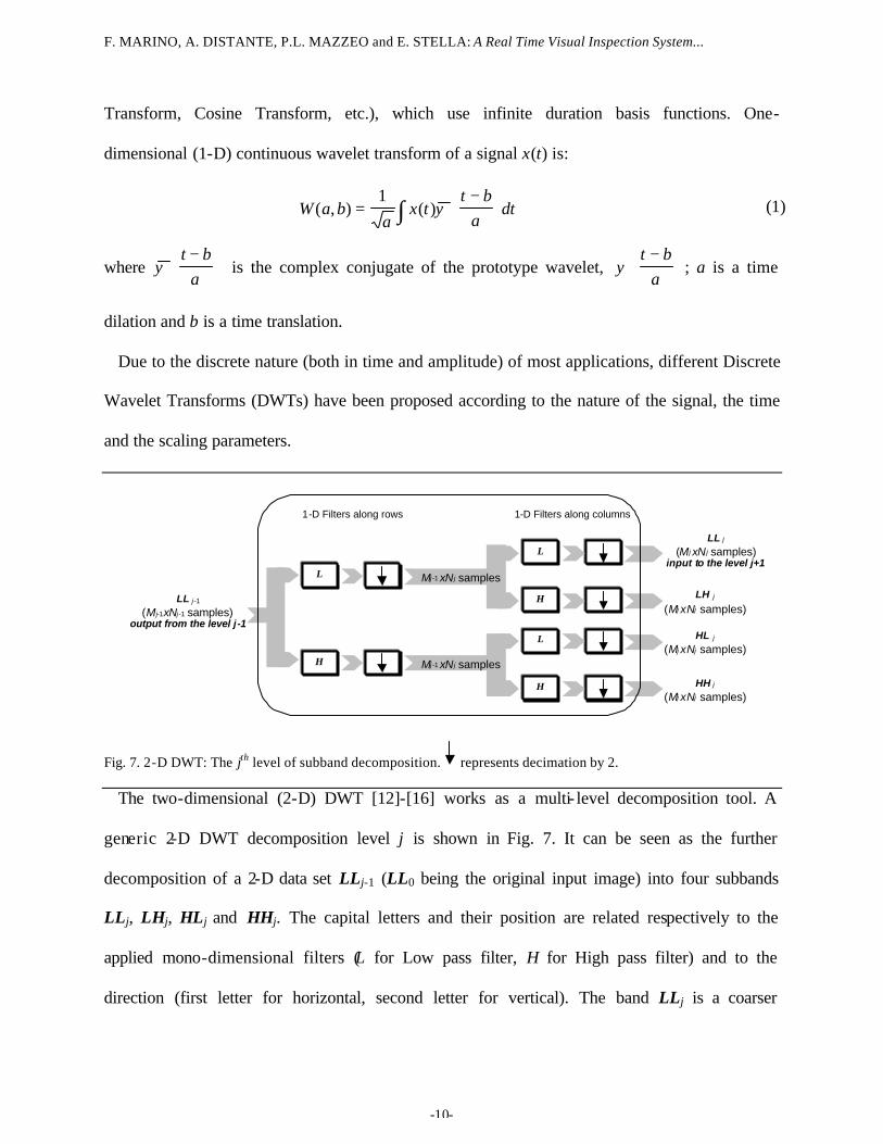
Fig. 7. 2-D DWT: The jth level of subband decomposition.
represents decimation by 2.
The two-dimensional (2-D) DWT [12]-[16] works as a multi- level decomposition tool. A
generic 2-D DWT decomposition level j is shown in Fig. 7. It can be seen as the further
decomposition of a 2-D data set LLj-1 (LL0 being the original input image) into four subbands
LLj, LHj, HLj and HHj. The capital letters and their position are related respectively to the
applied mono-dimensional filters (L for Low pass filter, H for High pass filter) and to the
direction (first letter for horizontal, second letter for vertical). The band LLj is a coarser
F. MARINO, A. DISTANTE, P.L. MAZZEO and E. STELLA: A Real Time Visual Inspection System...
-11-
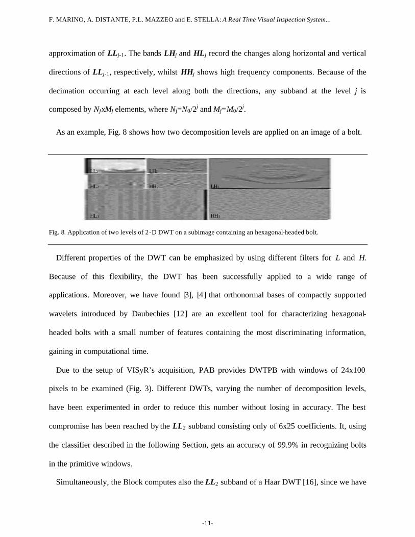
approximation of LLj-1. The bands LHj and HLj record the changes along horizontal and vertical
directions of LLj-1, respectively, whilst HHj shows high frequency components. Because of the
decimation occurring at each level along both the directions, any subband at the level j is
composed by NjxMj elements, where Nj=N0/2j and Mj=M0/2j.
As an example, Fig. 8 shows how two decomposition levels are applied on an image of a bolt.
LL2
HL2
LH2
HH2 LH1
HL1 HH1
Fig. 8. Application of two levels of 2-D DWT on a subimage containing an hexagonal-headed bolt.
Different properties of the DWT can be emphasized by using different filters for L and H.
Because of this flexibility, the DWT has been successfully applied to a wide range of
applications. Moreover, we have found [3], [4] that orthonormal bases of compactly supported
wavelets introduced by Daubechies [12] are an excellent tool for characterizing hexagonal-
headed bolts with a small number of features containing the most discriminating information,
gaining in computational time.
Due to the setup of VISyR’s acquisition, PAB provides DWTPB with windows of 24x100
pixels to be examined (Fig. 3). Different DWTs, varying the number of decomposition levels,
have been experimented in order to reduce this number without losing in accuracy. The best
compromise has been reached by the LL2 subband consisting only of 6x25 coefficients. It, using
the classifier described in the following Section, gets an accuracy of 99.9% in recognizing bolts
in the primitive windows.
Simultaneously, the Block computes also the LL2 subband of a Haar DWT [16], since we have
F. MARINO, A. DISTANTE, P.L. MAZZEO and E. STELLA: A Real Time Visual Inspection System...
-12-
found that the cross validation of two classifiers (processing respectively D_LL2 and H_LL2, i.e.,
the output of DDWT and HDWT, see Fig. 2) practically avoids false positive detection (see
Section VII.B).
V. MULTI LAYER PERCEPTRON NEURAL CLASSIFIER
Neural networks have been revealed useful tools for many applicative fields, such as extracting
data from images (e.g., [20]) and classifications (e.g., [21]). In our classification task, we have
focused our attention on neural networks. In fact:
- Neural network classifiers have a key advantage over geometry-based techniques
because they do not require a geometric model for the object representation [22];
- Neural network classifiers separate the classes using curve surfaces, by this way
outperforming K-NN classifiers, which separate the classes by means of linear surfaces.
Moreover, K-NN classifiers continuously iterate the training using as feedback the
results of the performed classifications, making themselves more complex and
computational expensive;
- Contrarily to the id-tree, neural networks have a topology very suitable for hardware
implementation.
Inside neural classifiers, we have chosen the MLP classifiers since in our previous works [3]
and [4], they have been revealed more precise than their counterpart RBF in the considered
application.
VISyR’s BDB employs two MLPNCs (DC and HC in Fig. 2), trained respectively for DDWT
and HDWT. DC and HC have an identical topology (they differ only for the values of the
weights) and are constituted by three layers of neurons (input, hidden and output layer). In the
following, DC is described; the functionalities of HC can be straightforwardly derived. The input
F. MARINO, A. DISTANTE, P.L. MAZZEO and E. STELLA: A Real Time Visual Inspection System...
-13-
layer is composed by 150 neurons '_ mnD (m=0..149) corresponding to the coefficients D_LL2(i,
j) of the subband D_LL2 according to:
( )25mod,25/_ 2' mmnD m D_LL= (2)
The hidden layer of DC [HC] consists of 10 neurons ''_ knD (k=0..9); they derive from the
propagation of the first layer according to:
+= ∑
=
149
0
'',
''' ____m
mkmkk nDwDbiasDfnD (3)
whilst the unique neuron '''0_ nD at the output layer is given by:
+= ∑
=
9
0
''''0,
'''''0 ____
kkk nDwDbiasDfnD (4)
where ',_ kmwD and ''
0,_ kwD are the weights respectively between first/second and second/third
layers. The activation function ( )xf , having range ]0, 1[, for both the layers, is:
( )xe
xf−+
=1
1 (5)
In this scenario, '''0_ nD ranges from 0 to 1 and indicates a measure of confidence on the
presence of the object to detect in the current image window, according to DC.
The outputs from DC and HC ( '''0_ nD and '''
0_ nH ) are combined as follows:
( ) ( )9.0_9.0_Presence '''0
'''0 >>= nHANDnD (6)
in order to produce the final output of the Classifier.
The biases and the weights are solved using the Error Back Propagation algorithm with an
adaptive learning rate [22] and a training set of more than 1,000 samples (see Section VII.A).
F. MARINO, A. DISTANTE, P.L. MAZZEO and E. STELLA: A Real Time Visual Inspection System...
-14-
VI. FPGA-BASED HARDWARE IMPLEMENTATION
Today, programmable logics play a strategic role in many fields. In fact, in the last two
decades, flexibility has been strongly required in order to meet the day-after-day shorter time-to-
market. Moreover, FPGAs are generally the first devices to be implemented on the state-of-art
silicon technology. Therefore, even if FPGAs were initially created for developing little glue-
logic, they currently often represent the core of various systems in different fields.
In order to allow VISyR to get real time performance, we have directly implemented in
hardware its most computational expensive blocks: DWTPB and MLPNCB (as well as RD&TB,
which, as previously said, is not described in this paper).
We have adopted as development platform Altera’s PCI High-Speed Development Kit,
Stratix™ Professional Edition, which, among other features [23], presents a Stratix™
EP1S60F1020C6 FPGA, 256-MByte PC333 DDR SDRAM, 32-bit or 64-bit PCI and 8/16-bit
different ial I/O up to 800 Mbps.
The Stratix™ EP1S60F1020C6 FPGA [24] is provided with 57,120 Look Up Table (LUT)-
based logic elements, 18 DSP blocks[1] and various memories of different size for globally
5,215,104 bits with a global maximum bandwidth of more than 10Tbits/s.
The software environment for friendly designing, simulating and testing is Altera’s Quartus
II™. Fig. 9 (on next page) shows a window of Quartus II™ CAD tool displaying a top- level
schematic of our design.
The architecture can be interpreted as a memory:
- The task starts when the host “writes” a 24x100 pixel window to be analysed. In this
phase, the host addresses the dual port memories inside the INPUT_INTERFACE (pin
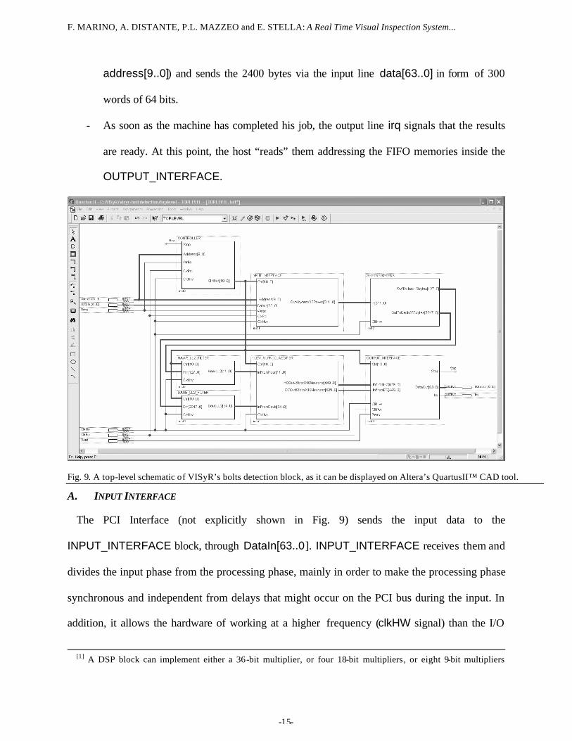
F. MARINO, A. DISTANTE, P.L. MAZZEO and E. STELLA: A Real Time Visual Inspection System...
-15-
address[9..0]) and sends the 2400 bytes via the input line data[63..0] in form of 300
words of 64 bits.
- As soon as the machine has completed his job, the output line irq signals that the results
are ready. At this point, the host “reads” them addressing the FIFO memories inside the
OUTPUT_INTERFACE.
Fig. 9. A top-level schematic of VISyR’s bolts detection block, as it can be displayed on Altera’s QuartusII™ CAD tool.
A. INPUT INTERFACE
The PCI Interface (not explicitly shown in Fig. 9) sends the input data to the
INPUT_INTERFACE block, through DataIn[63..0]. INPUT_INTERFACE receives them and
divides the input phase from the processing phase, mainly in order to make the processing phase
synchronous and independent from delays that might occur on the PCI bus during the input. In
addition, it allows the hardware of working at a higher frequency (clkHW signal) than the I/O
[1] A DSP block can implement either a 36-bit multiplier, or four 18-bit multipliers, or eight 9-bit multipliers
F. MARINO, A. DISTANTE, P.L. MAZZEO and E. STELLA: A Real Time Visual Inspection System...
-16-
(clkPCI signal).
B. DAUBECHIES DWT PREPROCESSING
Daubechies 2-D DWT preprocessing is performed by the cooperation of the
SHIFTREGISTERS block with the DAUB_LL2_FILTER block.
For saving hardware resources and computing time, we have discarded the floating point
processing mode and we have adopted fixed point precision[2]. Moreover, since we are interested
exclusively on the LL2 subband, we have focused our attention only on that.
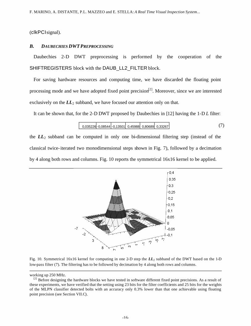
It can be shown that, for the 2-D DWT proposed by Daubechies in [12] having the 1-D L filter:
0,035226 -0,08544 -0,13501 0,45988 0,80689 0,33267 (7)
the LL2 subband can be computed in only one bi-dimensional filtering step (instead of the
classical twice- iterated two monodimensional steps shown in Fig. 7), followed by a decimation
by 4 along both rows and columns. Fig. 10 reports the symmetrical 16x16 kernel to be applied.
Fig. 10. Symmetrical 16x16 kernel for computing in one 2-D step the LL2 subband of the DWT based on the 1-D low-pass filter (7). The filtering has to be followed by decimation by 4 along both rows and columns. working up 250 MHz.
[2] Before designing the hardware blocks we have tested in software different fixed point precisions. As a result of these experiments, we have verified that the setting using 23 bits for the filter coefficients and 25 bits for the weights of the MLPN classifier detected bolts with an accuracy only 0.3% lower than that one achievable using floating point precision (see Section VII.C).
F. MARINO, A. DISTANTE, P.L. MAZZEO and E. STELLA: A Real Time Visual Inspection System...
-17-
We compute LL2 directly in only one 2-D step, because:
- this requires a controller much simpler than the one used by the separable approach (Fig.
7);
- separable approach is greatly efficient in computing all the four subbands of each level.
But VISyR’s classification process does not need other subbands than LL2;
- when fixed point precision is employed, each step of the separable approach produces
results with different dynamic, so doing, the hardware used at a certain step becomes
unusable for implementing the further steps;
- the error (due to the fixed point precision) generated in a unique step does not propagate
itself and can be easily controlled. Conversely, propagation occurs along four different
steps when LL2 is computed by means of separable approach.
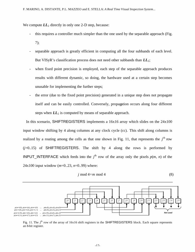
In this scenario, SHIFTREGISTERS implements a 16x16 array which slides on the 24x100
input window shifting by 4 along columns at any clock cycle (cc). This shift along columns is
realized by a routing among the cells as that one shown in Fig. 11, that represents the jth row
(j=0..15) of SHIFTREGISTERS. The shift by 4 along the rows is performed by
INPUT_INTERFACE which feeds into the jth row of the array only the pixels p(m, n) of the
24x100 input window (m=0..23, n=0..99) where:
j mod 4=m mod 4 (8)
p(m+4,8), p(m+4,4), p(m+4,0) ... p(m,8), p(m,4), p(m,0)
p(m+4,9), p(m+4,5), p(m+4, 1) ... p(m,9), p(m,5), p(m,1)
p(m+4,10), p(m+4,6), p(m+4,2) ... p(m,10), p(m,6), p(m,2) p(m+4,11), p(m+4,7), p(m+4,3) ... p(m,11), p(m,7), p(m,3)
Not used
j,0 j,1 j,2 j,3 j,4 j,5 j,6 j,7 j ,8 j,9 j,10 j,11 j,12 j,13 j ,14 j,15
Fig. 11. The jth row of the array of 16x16 shift registers in the SHIFTREGISTERS block. Each square represents an 8-bit register.
F. MARINO, A. DISTANTE, P.L. MAZZEO and E. STELLA: A Real Time Visual Inspection System...
-18-
At any cc, sixteen contiguous rows of the input window are fed in parallel into
SHIFTREGISTERS at the rate of 64 bytes/cc (4 bytes of each row for 16 rows) through
IN[511..0]. Simultaneously, all the 256 bytes latched in the 16x16 array are inputted in parallel
into DAUB_LL2_FILTER through OutToDaubLL256bytes[2047..0]. DAUB_LL2_FILTER
exploits the symmetry of the kernel (see Fig. 10), adding the pixels coming from the cells (j, l) to
those ones coming from the cells (l, j) (j=0..15, l=0..15); afterwards, it computes the products of
these sums and of the diagonal elements of the array by the related filter coefficients, and,
finally, it accumulates these products.
As a result, DAUB_LL2_FILTER produces the LL2 coefficients after a latency of 11 ccs and
at the rate of 1 coefficient/cc. These ones are now expressed in 35 bits, because of the growing of
the dynamic, and are input into 1LEV_MLPN_CLASSIFIER via InFromDaub[34..0].
We are not interested in higher throughput, since -because of FPGA hardware resources- our
neural classifier employs 10 multipliers and can manage 1 coefficient per cc (see Section VI.D).
C. HAAR DWT PREPROCESSING
Computationally, Haar Transform is a very simple DWT since its 1-D filters are: L=[1/2, 1/2]
and H=[1/2, -1/2]. Therefore, any coefficient H_LL2(i, j) can be computed in one step according
to:
∑∑=
=
=
=
++=3
0
3
02 )4,4(
161
),(l
l
k
k
ljkipjiH_LL (9)
In order to compute (9), we exploit the same SHIFTREGISTERS block used for performing
Daubechies DWT and a HAAR_LL2_FILTER block. HAAR_LL2_FILTER trivially adds[3] the
data coming from OutToHaar16bytes[255..0] which are the values of the pixels p(m, n) of the
4x4 window centered on the 16x16 sliding array implemented by SHIFTREGISTERS.
[3] The scaling by 16 is simply performed by a shift left of the fixed point of 4 positions.
F. MARINO, A. DISTANTE, P.L. MAZZEO and E. STELLA: A Real Time Visual Inspection System...
-19-
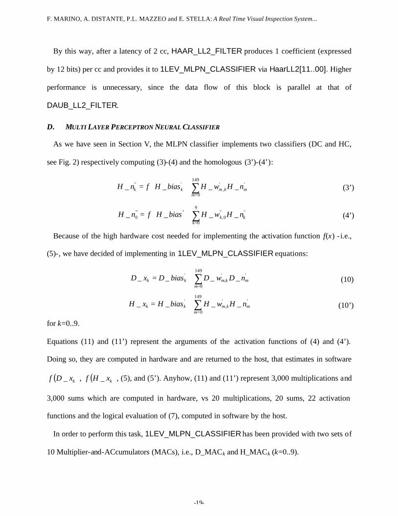
By this way, after a latency of 2 cc, HAAR_LL2_FILTER produces 1 coefficient (expressed
by 12 bits) per cc and provides it to 1LEV_MLPN_CLASSIFIER via HaarLL2[11..00]. Higher
performance is unnecessary, since the data flow of this block is parallel at that of
DAUB_LL2_FILTER.
D. MULTI LAYER PERCEPTRON NEURAL CLASSIFIER
As we have seen in Section V, the MLPN classifier implements two classifiers (DC and HC,
see Fig. 2) respectively computing (3)-(4) and the homologous (3’)-(4’):
+= ∑
=
149
0
'',
''' ____m
mkmkk nHwHbiasHfnH (3’)
+= ∑
=
9
0
''''0,
'''''0 ____
kkk nHwHbiasHfnH (4’)
Because of the high hardware cost needed for implementing the activation function f(x) - i.e.,
(5)-, we have decided of implementing in 1LEV_MLPN_CLASSIFIER equations:
∑=
+=149
0
'',
' ____m
mkmkk nDwDbiasDxD (10)
∑=
+=149
0
'',
' ____m
mkmkk nHwHbiasHxH (10’)
for k=0..9.
Equations (11) and (11’) represent the arguments of the activation functions of (4) and (4’).
Doing so, they are computed in hardware and are returned to the host, that estimates in software
( )kxDf _ , ( )kxHf _ , (5), and (5’). Anyhow, (11) and (11’) represent 3,000 multiplications and
3,000 sums which are computed in hardware, vs 20 multiplications, 20 sums, 22 activation
functions and the logical evaluation of (7), computed in software by the host.
In order to perform this task, 1LEV_MLPN_CLASSIFIER has been provided with two sets of
10 Multiplier-and-ACcumulators (MACs), i.e., D_MACk and H_MACk (k=0..9).
F. MARINO, A. DISTANTE, P.L. MAZZEO and E. STELLA: A Real Time Visual Inspection System...
-20-
As soon as a coefficient D_LL2(i, j) [H_LL2(i, j)] is produced by DAUB_LL2_FILTER
[HAAR_LL2_FILTER], the multipliers D_MACk [H_MACk] multiply it in parallel by ',_ kmwD
[ ',_ kmwH ] (m=25i+j, k=0..9) and continue in this way for 150 ccs, one cc for each one of the
150 coefficients of D_LL2 [H_LL2]. The weights ',_ kmwD and '
,_ kmwH have been preloaded in
20 LUTs during the setup (one LUT for each multiplier, each one storing 150 weights). The
accumulator of any D_MACk [H_MACk] is initialized with D_biask [H_biask] and it accumulates
the products as soon as they are output from the multipliers.
E. OUTPUT INTERFACE
Because of its latency, the task of 1LEV_MLPN_CLASSIFIER ends 5 ccs after the last
coefficients D_LL2(5, 24) and H_LL2(5, 24) are provided by DAUB_LL2_FILTER and by
HAAR_LL2_FILTER. At this point, the data stored in the 20 accumulators of D_MACk and
H_MACk (k=0..9) have now respectively 63 bits and 45 bits because of the growing of the
dynamic. They are sent to OUTPUT_INTERFACE via DCOut63bitsX10Neurons[629..0] and
HCOut45bitsX10Neurons[449..0].
These data are extended in sign and formatted in words of 64 bits by
OUTPUT_INTERFACE. Moreover, OUTPUT_INTERFACE serialize them using a FIFO and
signals on the irq output that the results are ready. Finally, the host requires these results (signal
read) and receives them on the DataOut[63..0] output (1 word/cc).
F. EMPLOYED HARDWARE RESOURCES
The architecture employs the resources summarized in Table I, which reports also a relative
count respect to the available resources on the Stratix™ EP1S60F1020C6 FPGA. The under-
utilization of these resources takes into account that also the RD&TB described in [2] has to be
F. MARINO, A. DISTANTE, P.L. MAZZEO and E. STELLA: A Real Time Visual Inspection System...
-21-
implemented on the same FPGA.
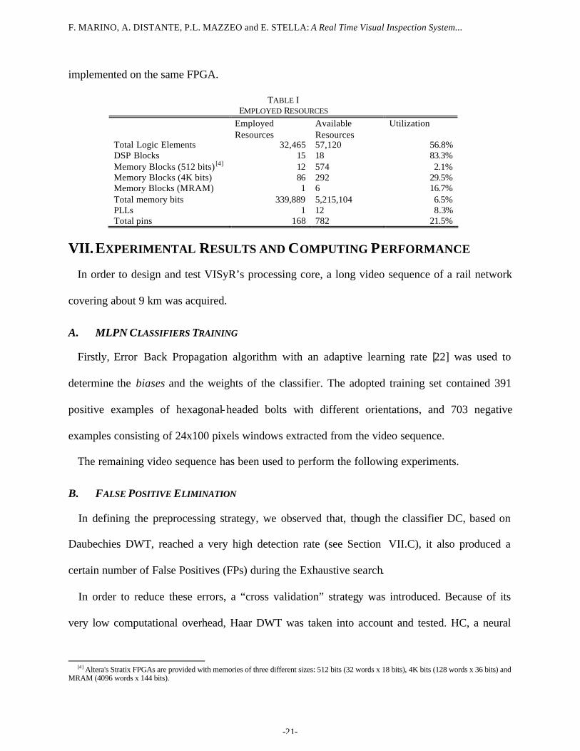
TABLE I EMPLOYED RESOURCES
Employed Resources
Available Resources
Utilization
Total Logic Elements 32,465 57,120 56.8% DSP Blocks 15 18 83.3% Memory Blocks (512 bits) [4] 12 574 2.1% Memory Blocks (4K bits) 86 292 29.5% Memory Blocks (MRAM) 1 6 16.7% Total memory bits 339,889 5,215,104 6.5% PLLs 1 12 8.3% Total pins 168 782 21.5%
VII. EXPERIMENTAL RESULTS AND COMPUTING PERFORMANCE
In order to design and test VISyR’s processing core, a long video sequence of a rail network
covering about 9 km was acquired.
A. MLPN CLASSIFIERS TRAINING
Firstly, Error Back Propagation algorithm with an adaptive learning rate [22] was used to
determine the biases and the weights of the classifier. The adopted training set contained 391
positive examples of hexagonal-headed bolts with different orientations, and 703 negative
examples consisting of 24x100 pixels windows extracted from the video sequence.
The remaining video sequence has been used to perform the following experiments.
B. FALSE POSITIVE ELIMINATION
In defining the preprocessing strategy, we observed that, though the classifier DC, based on
Daubechies DWT, reached a very high detection rate (see Section VII.C), it also produced a
certain number of False Positives (FPs) during the Exhaustive search.
In order to reduce these errors, a “cross validation” strategy was introduced. Because of its
very low computational overhead, Haar DWT was taken into account and tested. HC, a neural
[4] Altera's Stratix FPGAs are provided with memories of three different sizes: 512 bits (32 words x 18 bits), 4K bits (128 words x 36 bits) and
MRAM (4096 words x 144 bits).
F. MARINO, A. DISTANTE, P.L. MAZZEO and E. STELLA: A Real Time Visual Inspection System...
-22-
classifier working on the LL2 subband of the Haar DWT, was designed and trained. HC reaches
the same detection rate of DC, though revealing much more FPs.
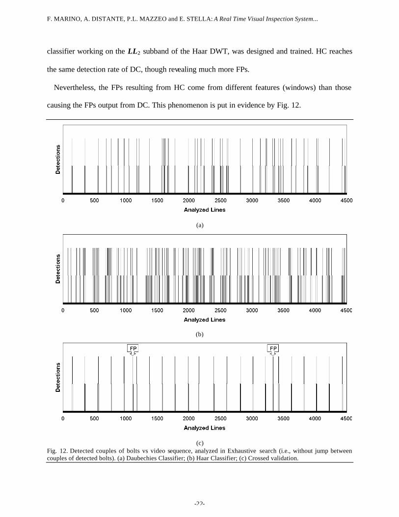
Nevertheless, the FPs resulting from HC come from different features (windows) than those
causing the FPs output from DC. This phenomenon is put in evidence by Fig. 12.
(a)
(b)
(c)
Fig. 12. Detected couples of bolts vs video sequence, analyzed in Exhaustive search (i.e., without jump between couples of detected bolts). (a) Daubechies Classifier; (b) Haar Classifier; (c) Crossed validation.
F. MARINO, A. DISTANTE, P.L. MAZZEO and E. STELLA: A Real Time Visual Inspection System...
-23-
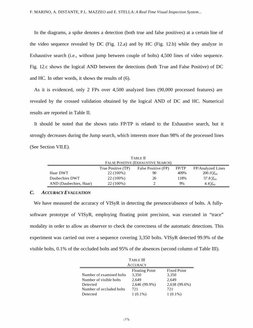
In the diagrams, a spike denotes a detection (both true and false positives) at a certain line of
the video sequence revealed by DC (Fig. 12.a) and by HC (Fig. 12.b) while they analyze in
Exhaustive search (i.e., without jump between couple of bolts) 4,500 lines of video sequence.
Fig. 12.c shows the logical AND between the detections (both True and False Positive) of DC
and HC. In other words, it shows the results of (6).
As it is evidenced, only 2 FPs over 4,500 analyzed lines (90,000 processed features) are
revealed by the crossed validation obtained by the logical AND of DC and HC. Numerical
results are reported in Table II.
It should be noted that the shown ratio FP/TP is related to the Exhaustive search, but it
strongly decreases during the Jump search, which interests more than 98% of the processed lines
(See Section VII.E).
TABLE II FALSE POSITIVE (EXHAUSTIVE SEARCH)
True Positive (TP) False Positive (FP) FP/TP FP/Analyzed Lines Haar DWT 22 (100%) 90 409% 000
00.200 Daubechies DWT 22 (100%) 26 118%
00008.57
AND (Daubechies, Haar) 22 (100%) 2 9% 00004.4
C. ACCURACY EVALUATION
We have measured the accuracy of VISyR in detecting the presence/absence of bolts. A fully-
software prototype of VISyR, employing floating point precision, was executed in “trace”
modality in order to allow an observer to check the correctness of the automatic detections. This
experiment was carried out over a sequence covering 3,350 bolts. VISyR detected 99.9% of the
visible bolts, 0.1% of the occluded bolts and 95% of the absences (second column of Table III).
TABLE III ACCURACY
Floating Point Fixed Point Number of examined bolts 3,350 3,350 Number of visible bolts 2,649 2,649 Detected 2,646 (99.9%) 2,638 (99.6%) Number of occluded bolts 721 721 Detected 1 (0.1%) 1 (0.1%)
F. MARINO, A. DISTANTE, P.L. MAZZEO and E. STELLA: A Real Time Visual Inspection System...
-24-
Number of absent bolts 21 21 Detected 20 (95%) 20 (95%)
D. HARDWARE DESIGN DEFINITION
The report (file log) obtained from the above experiment was used as term of comparison for
the reports of similar experiments aiming at defining the number of bits per words to be used in
the hardware design. The fully-software prototype of VISyR was modified changing the floating
point operating mode into the fixed point mode. Different versions of VISyR were compiled with
different precisions (i.e., number of bits) both for Daubechies filter coefficients and for the
weights of DC and HC. The setting with 23 bits for the filter coefficients and with 25 bits for the
weights of both the classifiers led to detect visible bolts with accuracy only 0.3% lower than that
obtained using floating point precision (third column of Table II). This setting was considered
acceptable, and the hardware design was developed using these specifications.
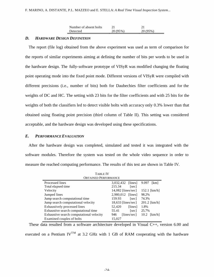
E. PERFORMANCE EVALUATION
After the hardware design was completed, simulated and tested it was integrated with the
software modules. Therefore the system was tested on the whole video sequence in order to
measure the reached computing performance. The results of this test are shown in Table IV.
TABLE IV OBTAINED PERFORMANCE
Processed lines 3,032,432 [lines] 9.097 [km] Total elapsed time 215.34 [sec] Velocity 14,082 [lines/sec] 152.1 [km/h]
Jumped lines 2,980,012 [lines] 98.2%
Jump search computational time 159.93 [sec] 74.3% Jump search computational velocity 18,633 [lines/sec] 201.2 [km/h] Exhaustively processed lines 52,420 [lines] 1.8% Exhaustive search computational time 55.41 [sec] 25.7% Exhaustive search computational velocity 946 [lines/sec] 10.2 [km/h] Examined couples of bolts 15,027
These data resulted from a software architecture developed in Visual C++, version 6.00 and
executed on a Pentium IVTM at 3.2 GHz with 1 GB of RAM cooperating with the hardware
F. MARINO, A. DISTANTE, P.L. MAZZEO and E. STELLA: A Real Time Visual Inspection System...
-25-
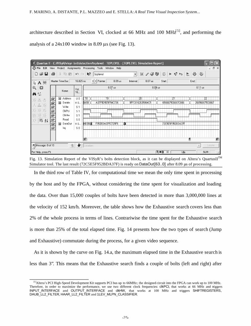
architecture described in Section VI, clocked at 66 MHz and 100 MHz[5], and performing the
analysis of a 24x100 window in 8.09 µs (see Fig. 13).
Fig. 13. Simulation Report of the VISyR’s bolts detection block, as it can be displayed on Altera’s QuartusIITM Simulator tool. The last result (72C5E5F952BDA37F) is ready on DataOut[63..0] after 8.09 µs of processing.
In the third row of Table IV, for computational time we mean the only time spent in processing
by the host and by the FPGA, without considering the time spent for visualization and loading
the data. Over than 15,000 couples of bolts have been detected in more than 3,000,000 lines at
the velocity of 152 km/h. Moreover, the table shows how the Exhaustive search covers less than
2% of the whole process in terms of lines. Contrariwise the time spent for the Exhaustive search
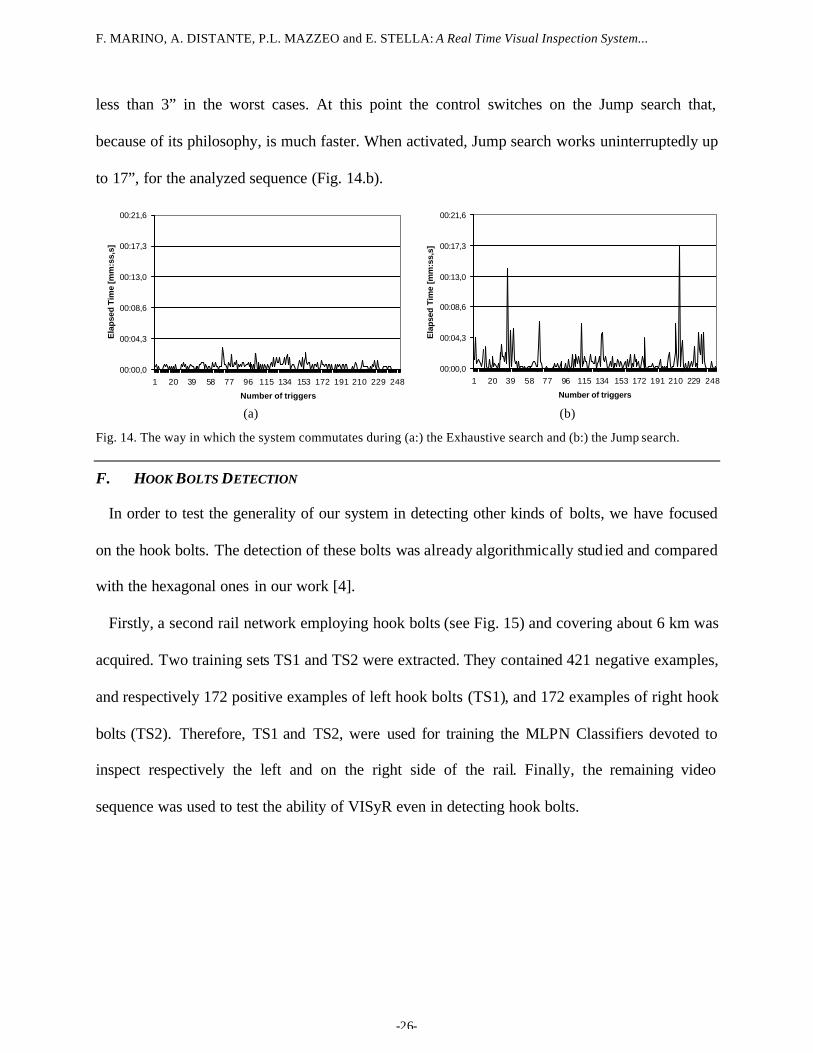
is more than 25% of the total elapsed time. Fig. 14 presents how the two types of search (Jump
and Exhaustive) commutate during the process, for a given video sequence.
As it is shown by the curve on Fig. 14.a, the maximum elapsed time in the Exhaustive search is
less than 3”. This means that the Exhaustive search finds a couple of bolts (left and right) after
[5]Altera’s PCI High-Speed Development Kit supports PCI bus up to 66MHz; the designed circuit into the FPGA can work up to 100 MHz.
Therefore, in order to maximize the performance, we use two different clock frequencies: clkPCI, that works at 66 MHz and triggers INPUT_INTERFACE and OUTPUT_INTERFACE and clkHW, that works at 100 MHz and triggers SHIFTREGISTERS, DAUB_LL2_FILTER, HAAR_LL2_FILTER and 1LEV_MLPN_CLASSIFIER.
F. MARINO, A. DISTANTE, P.L. MAZZEO and E. STELLA: A Real Time Visual Inspection System...
-26-
less than 3” in the worst cases. At this point the control switches on the Jump search that,
because of its philosophy, is much faster. When activated, Jump search works uninterruptedly up
to 17”, for the analyzed sequence (Fig. 14.b).
00:00,0
00:04,3
00:08,6
00:13,0
00:17,3
00:21,6
1 20 39 58 77 96 115 134 153 172 191 210 229 248
Number of triggers
Ela
pse
d T
ime
[mm
:ss,
s]
00:00,0
00:04,3
00:08,6
00:13,0
00:17,3
00:21,6
1 20 39 58 77 96 115 134 153 172 191 210 229 248
Number of triggers
Ela
psed
Tim
e [m
m:s
s,s]
(a) (b)
Fig. 14. The way in which the system commutates during (a:) the Exhaustive search and (b:) the Jump search.
F. HOOK BOLTS DETECTION
In order to test the generality of our system in detecting other kinds of bolts, we have focused
on the hook bolts. The detection of these bolts was already algorithmically studied and compared
with the hexagonal ones in our work [4].
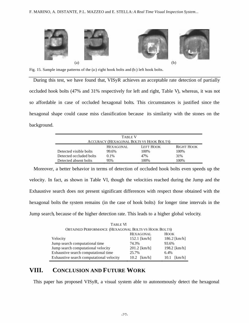
Firstly, a second rail network employing hook bolts (see Fig. 15) and covering about 6 km was
acquired. Two training sets TS1 and TS2 were extracted. They contained 421 negative examples,
and respectively 172 positive examples of left hook bolts (TS1), and 172 examples of right hook
bolts (TS2). Therefore, TS1 and TS2, were used for training the MLPN Classifiers devoted to
inspect respectively the left and on the right side of the rail. Finally, the remaining video
sequence was used to test the ability of VISyR even in detecting hook bolts.
F. MARINO, A. DISTANTE, P.L. MAZZEO and E. STELLA: A Real Time Visual Inspection System...
-27-
(a) (b)
Fig. 15. Sample image patterns of the (a:) right hook bolts and (b:) left hook bolts.
During this test, we have found that, VISyR achieves an acceptable rate detection of partially
occluded hook bolts (47% and 31% respectively for left and right, Table V), whereas, it was not
so affordable in case of occluded hexagonal bolts. This circumstances is justified since the
hexagonal shape could cause miss classification because its similarity with the stones on the
background.
TABLE V ACCURACY (HEXAGONAL BOLTS VS HOOK BOLTS)
HEXAGONAL LEFT HOOK RIGHT HOOK Detected visible bolts 99.6% 100% 100% Detected occluded bolts 0.1% 47% 31% Detected absent bolts 95% 100% 100%
Moreover, a better behavior in terms of detection of occluded hook bolts even speeds up the
velocity. In fact, as shown in Table VI, though the velocities reached during the Jump and the
Exhaustive search does not present significant differences with respect those obtained with the
hexagonal bolts the system remains (in the case of hook bolts) for longer time intervals in the
Jump search, because of the higher detection rate. This leads to a higher global velocity.
TABLE VI OBTAINED PERFORMANCE (HEXAGONAL BOLTS VS HOOK BOLTS)
HEXAGONAL HOOK Velocity 152.1 [km/h] 186.2 [km/h]
Jump search computational time 74.3% 93.6% Jump search computational velocity 201.2 [km/h] 198.2 [km/h] Exhaustive search computational time 25.7% 6.4% Exhaustive search computational velocity 10.2 [km/h] 10.1 [km/h]
VIII. CONCLUSION AND FUTURE WORK
This paper has proposed VISyR, a visual system able to autonomously detect the hexagonal
F. MARINO, A. DISTANTE, P.L. MAZZEO and E. STELLA: A Real Time Visual Inspection System...
-28-
headed bolts that secure the rail to the sleepers.
Versions of VISyR targeted to detect the absence/presence of other types of fastening bolts
employed in railway infrastructures can be straightforwardly derived because of the flexibility of
our FPGA-based implementation. In particular, detection of hook bolts have been even tested
downloading onto the FPGA different set of neural weights, generated by a proper training step.
The implemented prediction algorithm and the FPGA-based architecture allow to speed up the
system performance in terms of the inspection velocity: VISyR analyses video at 201 km/h
(Jump search) and at 10 km/h (Exhaustive search), reaching a composite velocity of 152 km/h
for the tested video sequence covering more than 9 km.
If the system remains in the Jump phase for a long time, performance can increase
subsequently. Next work will be addressed in this direction, for example, automatically skipping
those areas where the fastening elements are covered by asphalt (i.e., level crossing, where
Exhaustive search is executed in continuous). Other future works could be addressed as follows:
- Our FPGA-based architecture performs the analysis of a window in 8.09 µs, but a
significant part of the input phase (6.82 µs, i.e., 84% of the whole interval) cannot be
overlapped (pipelined) with any other computation. Future research will deal with this
bottleneck, for instance developing the FPGA-architecture on the same board where the
frame grabber is located, avoiding the need for PCI input.
- As we have seen in Section V, the activation function in MLPNCB is computed in
software, because of its high hardware requirement. Nevertheless, a hardware
implementation could further improve the performance. At the moment, we are
considering the possibility of using a hybrid method which computes the activation
F. MARINO, A. DISTANTE, P.L. MAZZEO and E. STELLA: A Real Time Visual Inspection System...
-29-
function directly (in the interval of its linear behavior) and maps it in LUTs (sub
sampling the non- linear interval).
However, VISyR constitutes a significant aid to the personnel in the railway safety issue
because of its high reliability, robustness and accuracy (99.6% visible bolts and 95% absent bolts
correctly detected). Moreover, its computing performance allows a more frequent ma intenance
of the entire railway network.
ACKNOWLEDGMENTS
The authors acknowledge Achille Montanaro, Altera Corporation, and the anonymous
reviewers for their helpful comments which have improved this work. The authors would also
like to thank Gianluigi and Pasquale De Ruvo for running simulations on Quartus II™.
REFERENCES
[1] A. Distante, F. Marino, P.L. Mazzeo, M. Nitti and E. Stella, “Metodo e Sistema
Automatico di Ispezione Visuale di una Infrastruttura”, (in Italian) Italian Industrial Patent
N. RM2005A000381, owned by the Italian National Research Council, 2005.
[2] F. Marino, et al. “A Real Time Visual Inspection System for Railway Maintenance:
Automatic Rail Detection and Tracking”, Internal Report DEE - Politecnico di Bari, 2005.
[3] E. Stella, P.L. Mazzeo, M. Nitti, G. Cicirelli, A. Distante and T. D’Orazio, “Visual
recognition of missing fastening elements for railroad maintenance,” IEEE-ITSC
International Conference on Intelligent Transportation System, pp. 94-99, Singapore,
2002.
[4] P.L. Mazzeo, M. Nitti, E. Stella and A. Distante, “Visual recognition of fastening bolts for
railroad maintenance,” Pattern Recognition Letters, vol. 25 n. 6, pp. 669-677, 2004.
[5] C. Alippi, E. Casagrande, F. Scotti, and V. Piuri, “Composite Real-Time Image Processing
for Railways Track Profile Measurement,” IEEE Trans. Instrumentation and
Measurement, vol. 49, N. 3, pp. 559-564, June 2000.
F. MARINO, A. DISTANTE, P.L. MAZZEO and E. STELLA: A Real Time Visual Inspection System...
-30-
[6] K Sato, H. Arai, T. Shimuzu, and M. Takada, “Obstruction Detector Using Ultrasonic
Sensors for Upgrading the Safety of a Level Crossing,” Proceedings of the IEE
International Conference on Developments in Mass Transit Systems, pp. 190-195, April
1998.
[7] W. Xishi, N. Bin, and C. Yinhang, “A new microprocessor based approach to an automatic
control system for railway safety,” Proceedings of the IEEE International Symposium on
Industrial Electronics, vol. 2, pp. 842-843, May 1992.
[8] Cybernetix Group (France), “IVOIRE: a system for rail inspection,” internal
documentation, http://www.cybernetix.fr
[9] Benntec Systemtechnik Gmbh, “RAILCHECK: image processing for rail analysis,”
internal documentation, http://www.benntec.com
[10] A. Rubaai, “A neural-net-based device for monitoring Amtrak railroad track system,”
IEEE Transactions on Industry Applications, vol. 39, N. 2 , pp. 374-381, March-April
2003.
[11] M. Yinghua, Z. Yutang, L. Zhongcheng, and Y. Cheng Ye, “A fail-safe microprocessor-
based system for interlocking on railways,” Proceedings of the Annual Symposium on
Reliability and Maintainability, pp. 415-420, Jan. 1994.
[12] I. Daubechies, “Orthonormal bases of compactly supported wavelets,” Comm. Pure &
Appl. Math., vol. 41, pp. 909-996, 1988.
[13] S. G. Mallat, “A Theory for Quadriresolution Signal Decomposition: The Wavelet
Representation,” IEEE Trans. Pattern Analysis and Machine Intelligence, vol. 2, pp. 674-
693, 1989.
[14] I. Daubechies, “The Wavelet Transform, Time Frequency, Localization and Signal
Analysis,” IEEE Trans. on Information Theory, vol. 36, n. 5, pp. 961-1005, Sept. 1990.
[15] M. Antonini, M. Barlaud, P. Mathieu and I. Daubechies, “Image Coding Using Wavelet
Transform,” IEEE Trans. Image Processing, Vol. 1, pp. 205-220, 1992.
[16] G. Strang, and T. Nuguyen, Wavelet and Filter banks, Wellesley College, 1996.
[17] http://vfm.dalsa.com/products/features/piranha2.asp
[18] “CAMERALINK: specification for camera link interface standard for digital cameras and
frame grabbers,” www.machinevisiononline.org
[19] http://www.coreco.com
F. MARINO, A. DISTANTE, P.L. MAZZEO and E. STELLA: A Real Time Visual Inspection System...
-31-
[20] M.T. Musavi, K.H. Chan, D.M. Hummels, K. Kalantri, “On the generalization ability of
neural network classifiers,” IEEE Trans. Pattern Analysis and Machine Intelligence, vol.
16, N. 6, pp. 659-663, June 1994.
[21] G.P. Zhang, “Neural networks for classification: a survey,” IEEE Transactions on Systems,
Man and Cybernetics, Part C, vol. 30, n. 4, pp. 451-462, Nov. 2000.
[22] M. Bishop, Neural Networks for Pattern Recognition, New York, Oxford, pp. 164-191,
1995.
[23] http://www.altera.com/products/devkits/altera/kit-pci_stx_pro.html
[24] http://www.altera.com/literature/hb/stx/stratix_handbook.pdf.