Embed Size (px)
Citation preview
A Reconfigurable Architecturefor
Load-Balanced Rendering
Graphics Hardware July 31, 2005, Los Angeles, CA
Jiawen ChenMichael I. GordonWilliam ThiesMatthias ZwickerKari PulliFrédo Durand
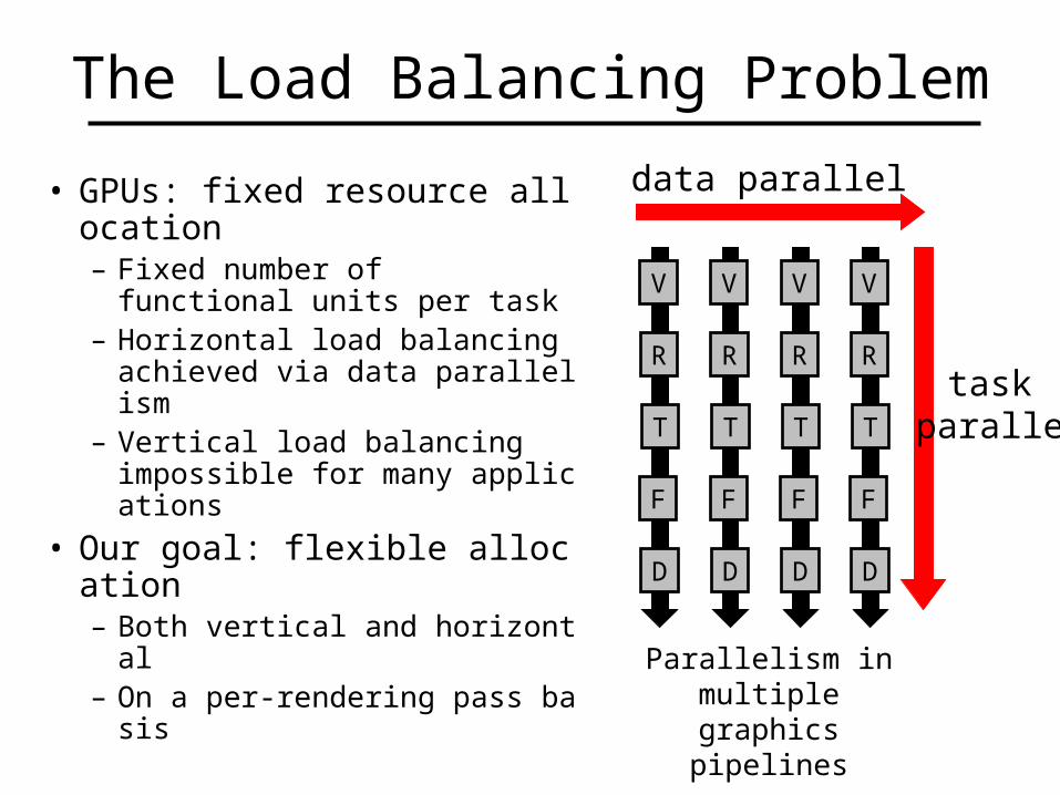
The Load Balancing Problem
• GPUs: fixed resource allocation– Fixed number of
functional units per task– Horizontal load balancing achie
ved via data parallelism– Vertical load balancing
impossible for many applications
• Our goal: flexible allocation– Both vertical and horizontal– On a per-rendering pass basis
V
R
T
F
D
V
R
T
F
D
V
R
T
F
D
V
R
T
F
D
task parallel
data parallel
Parallelism in multiple graphics pipelines
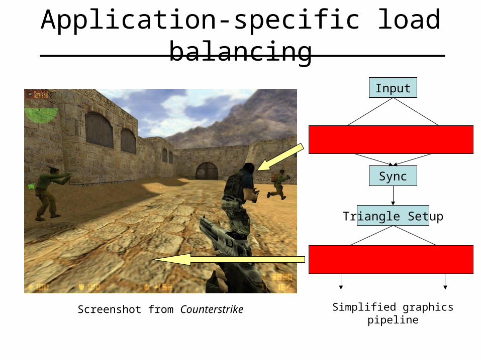
Application-specific load balancing
Screenshot from Counterstrike
Input
Vertex Vertex
Sync
Triangle Setup
Pixel Pixel
V
P
Simplified graphics pipeline
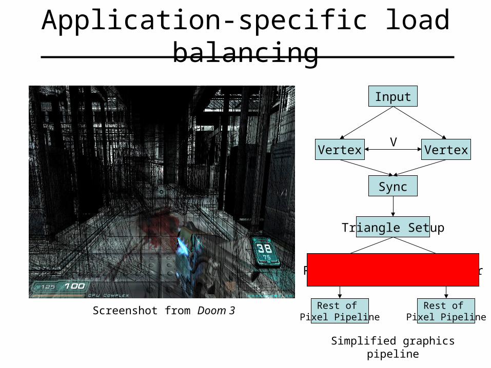
Application-specific load balancing
Screenshot from Doom 3
Input
Vertex Vertex
Sync
Triangle Setup
V
R
Simplified graphics pipeline
Rest of Pixel Pipeline
Rest of Pixel Pipeline
Rasterizer Rasterizer
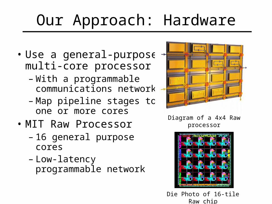
Our Approach: Hardware
• Use a general-purpose multi-core processor– With a programmable
communications network– Map pipeline stages to one
or more cores
• MIT Raw Processor– 16 general purpose cores– Low-latency programmable
network
Die Photo of 16-tile Raw chip
Diagram of a 4x4 Raw processor
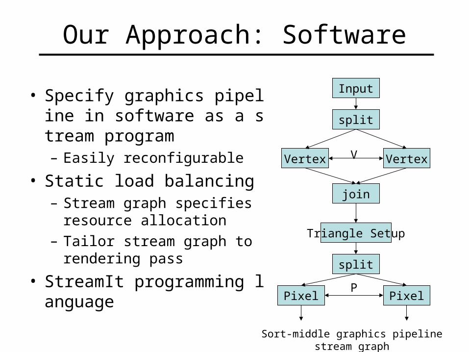
Our Approach: Software
• Specify graphics pipeline in software as a stream program– Easily reconfigurable
• Static load balancing– Stream graph specifies resourc
e allocation
– Tailor stream graph to rendering pass
• StreamIt programming language
Input
Vertex Vertex
join
split
Triangle Setup
split
Pixel Pixel
V
P
Sort-middle graphics pipeline stream graph
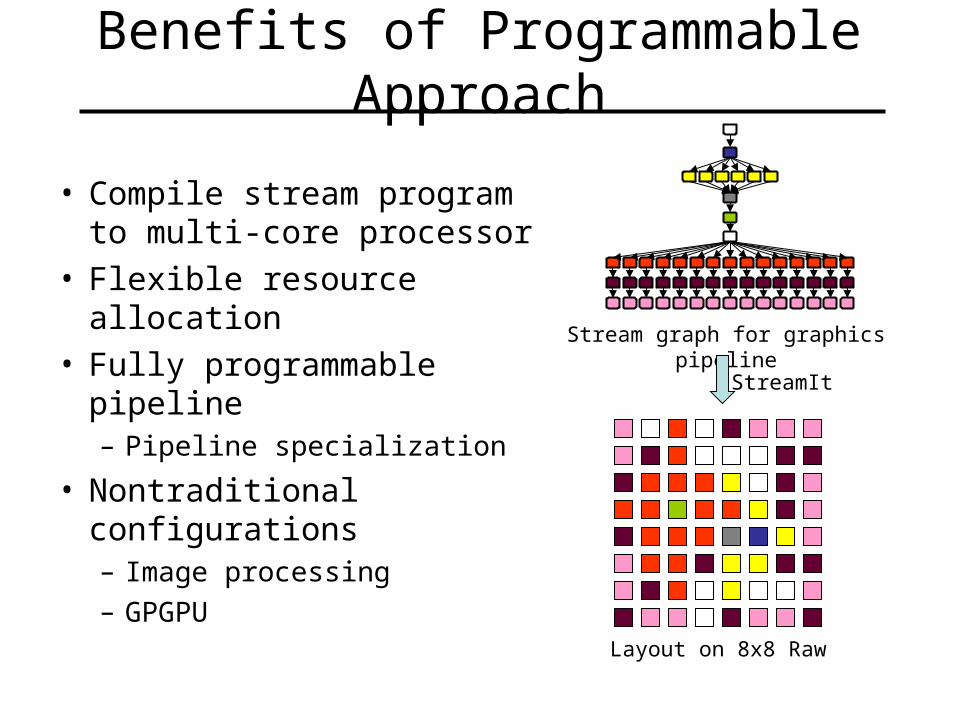
Benefits of Programmable Approach
• Compile stream program to multi-core processor
• Flexible resource allocation• Fully programmable pipeline
– Pipeline specialization
• Nontraditional configurations– Image processing
– GPGPU
Stream graph for graphics pipeline
StreamIt
Layout on 8x8 Raw

Related Work
• Scalable Architectures– Pomegranate [Eldridge et al., 2000]
• Streaming Architectures– Imagine [Owens et al., 2000]
• Unified Shader Architectures– ATI Xenos
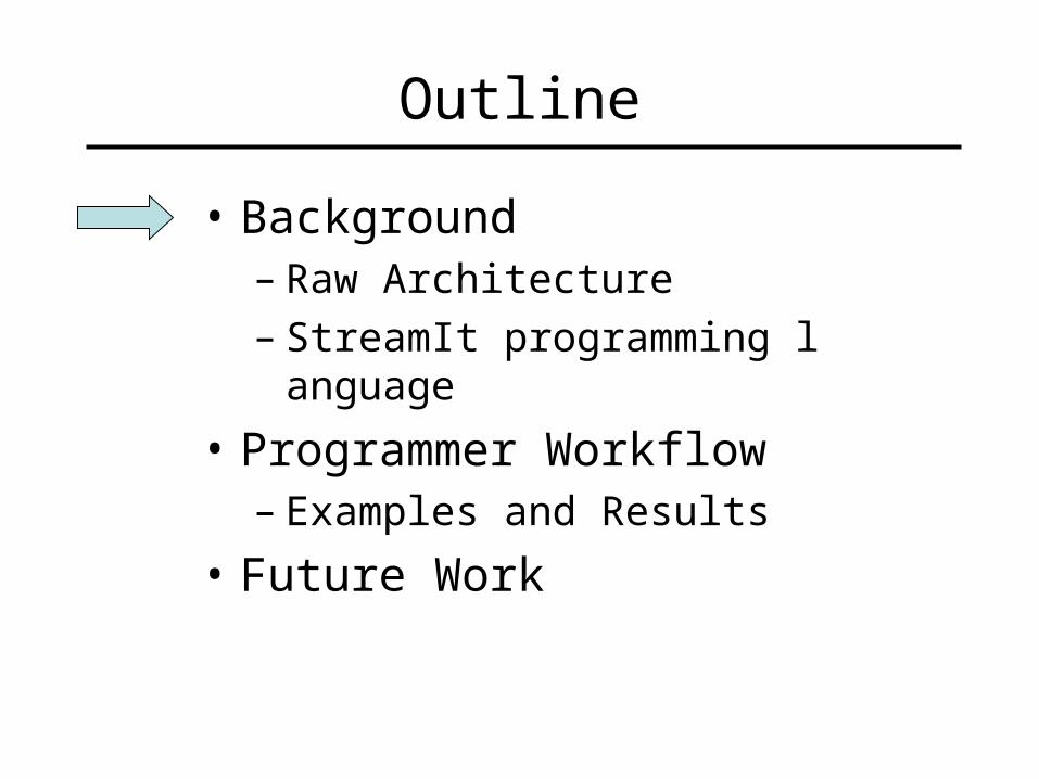
Outline
• Background– Raw Architecture– StreamIt programming language
• Programmer Workflow– Examples and Results
• Future Work
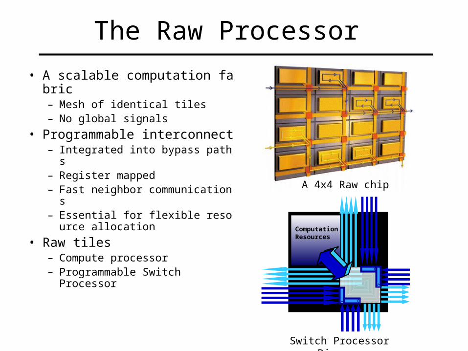
The Raw Processor
• A scalable computation fabric– Mesh of identical tiles– No global signals
• Programmable interconnect– Integrated into bypass paths– Register mapped– Fast neighbor communications– Essential for flexible resource al
location
• Raw tiles– Compute processor– Programmable Switch Processor
A 4x4 Raw chip
ComputationResources
Switch Processor Diagram
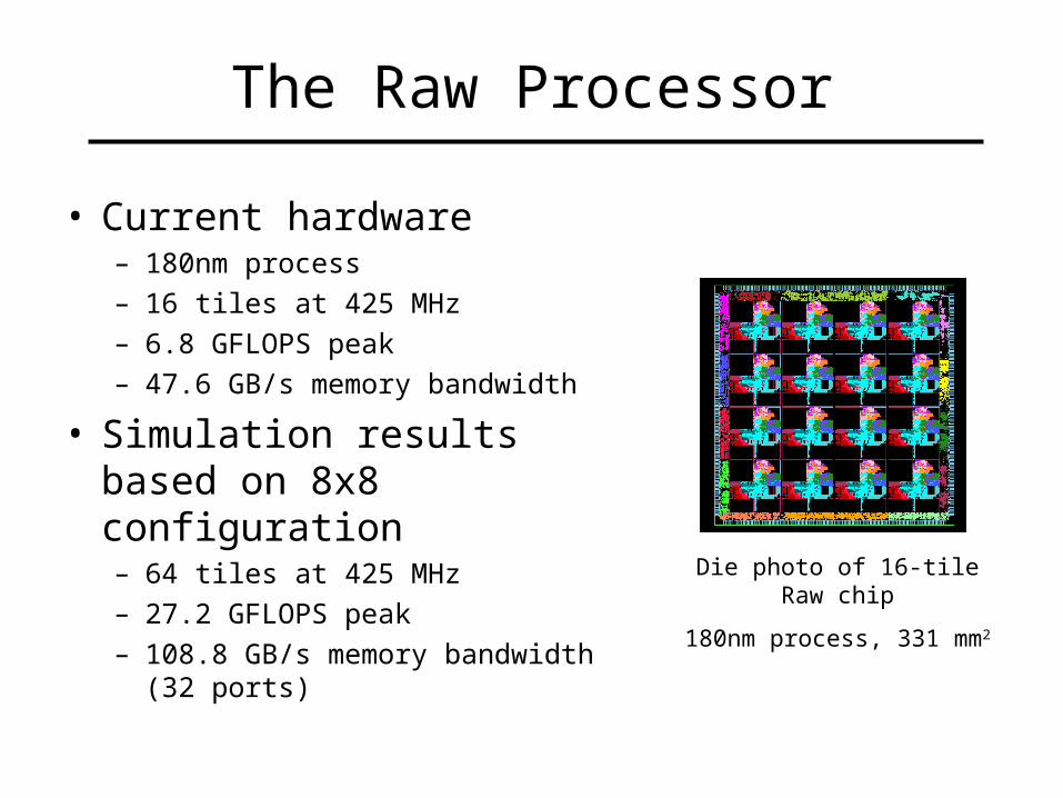
The Raw Processor
• Current hardware– 180nm process
– 16 tiles at 425 MHz
– 6.8 GFLOPS peak
– 47.6 GB/s memory bandwidth
• Simulation results based on 8x8 configuration– 64 tiles at 425 MHz
– 27.2 GFLOPS peak
– 108.8 GB/s memory bandwidth (32 ports)
Die photo of 16-tile Raw chip
180nm process, 331 mm2
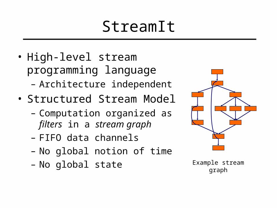
StreamIt
• High-level stream programming language– Architecture independent
• Structured Stream Model– Computation organized as filters in a
stream graph
– FIFO data channels
– No global notion of time
– No global state Example stream graph
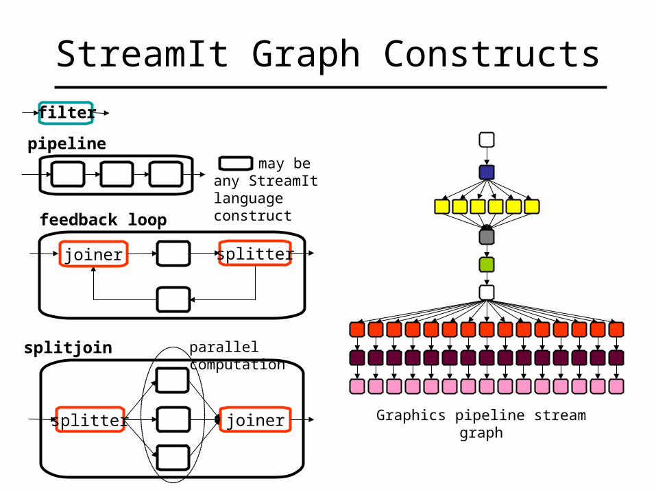
StreamIt Graph Constructs
parallel computation
may be any StreamIt language construct
joinersplitter
pipeline
feedback loop
joiner splitter
splitjoin
filter
Graphics pipeline stream graph
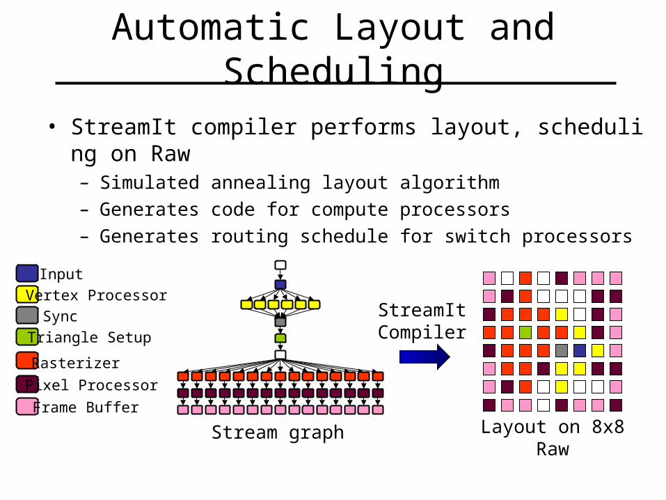
Automatic Layout and Scheduling
• StreamIt compiler performs layout, scheduling on Raw– Simulated annealing layout algorithm
– Generates code for compute processors
– Generates routing schedule for switch processors
Layout on 8x8 Raw
Input
Vertex Processor
Sync
Triangle Setup
Rasterizer
Pixel Processor
Frame Buffer
StreamIt Compiler
Stream graph
Outline
• Background– Raw Architecture– StreamIt programming language
• Programmer Workflow– Examples and Results
• Future Work
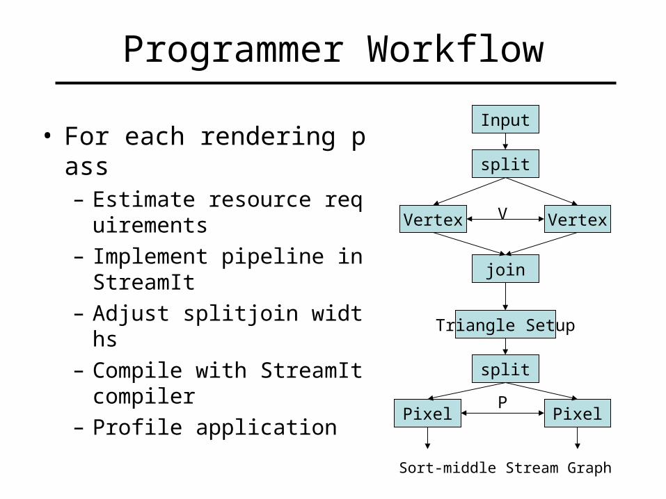
Programmer Workflow
• For each rendering pass– Estimate resource requirement
s
– Implement pipeline in StreamIt
– Adjust splitjoin widths
– Compile with StreamIt compiler
– Profile application
Input
Vertex Vertex
join
split
Triangle Setup
split
Pixel Pixel
V
P
Sort-middle Stream Graph

Switching Between Multiple Configurations
• Multi-pass rendering algorithms– Switch configurations between passes
– Pipeline flush required anyway (e.g. shadow volumes)
Configuration 1 Configuration 2
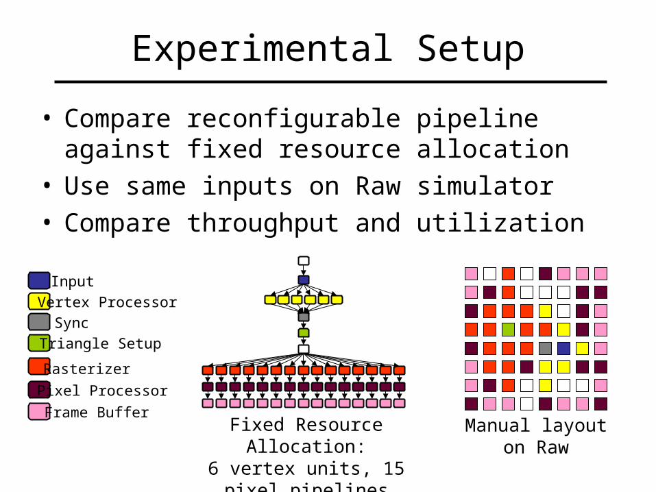
Experimental Setup
• Compare reconfigurable pipeline against fixed resource allocation
• Use same inputs on Raw simulator• Compare throughput and utilization
Manual layout on RawFixed Resource Allocation:6 vertex units, 15 pixel pipelines
Input
Vertex Processor
Sync
Triangle Setup
Rasterizer
Pixel Processor
Frame Buffer

Example: Phong Shading
• Per-pixel phong-shaded polyhedron
• 162 vertices, 1 light• Covers large area of screen• Allocate only 1 vertex unit• Exploit task parallelism
– Devote 2 tiles to pixel shader– 1 for computing the lighting d
irection and normal– 1 for shading
• Pipeline specialization– Eliminate texture coordinate i
nterpolation, etcOutput, rendered using the Raw simulator
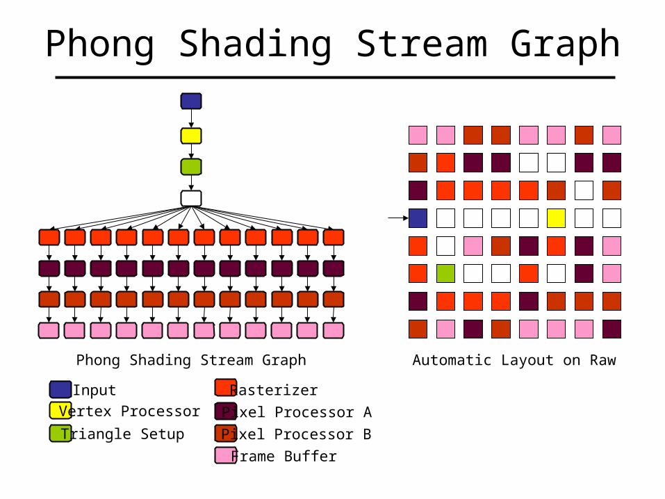
Phong Shading Stream Graph
Input
Vertex Processor
Triangle Setup
Rasterizer
Pixel Processor A
Frame Buffer
Pixel Processor B
Phong Shading Stream Graph Automatic Layout on Raw
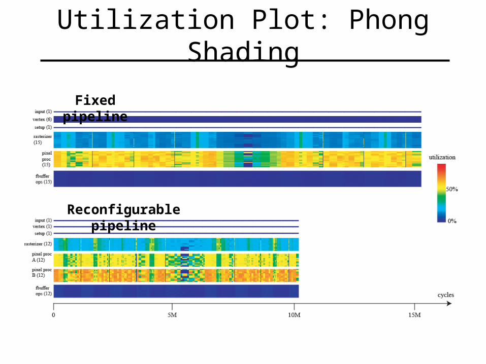
Utilization Plot: Phong Shading
Fixed pipeline
Reconfigurable pipeline
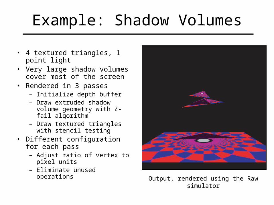
Example: Shadow Volumes
• 4 textured triangles, 1 point light• Very large shadow volumes cover
most of the screen• Rendered in 3 passes
– Initialize depth buffer– Draw extruded shadow volume
geometry with Z-fail algorithm– Draw textured triangles with
stencil testing
• Different configuration for each pass– Adjust ratio of vertex to pixel
units– Eliminate unused operations
Output, rendered using the Raw simulator
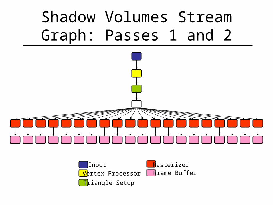
Shadow Volumes Stream Graph: Passes 1 and 2
Input
Vertex Processor
Triangle Setup
RasterizerFrame Buffer
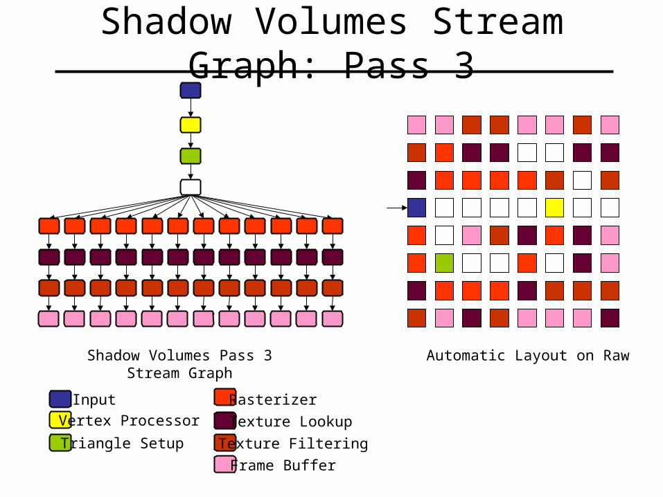
Shadow Volumes Stream Graph: Pass 3
Input
Vertex Processor
Triangle Setup
Rasterizer
Texture Lookup
Frame Buffer
Texture Filtering
Shadow Volumes Pass 3 Stream Graph Automatic Layout on Raw
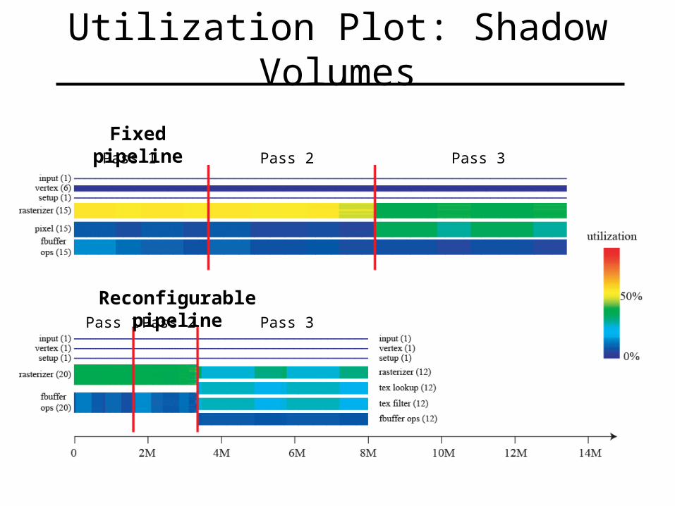
Utilization Plot: Shadow Volumes
Fixed pipeline
Reconfigurable pipeline
Pass 1 Pass 2 Pass 3
Pass 1 Pass 2 Pass 3
Limitations
• Software rasterization is extremely slow– 55 cycles per fragment
• Memory system– Technique does not optimize for texture access
Future Work
• Augment Raw with special purpose hardware• Explore memory hierarchy
– Texture prefetching– Cache performance
• Single-pass rendering algorithms– Load imbalances may occur within a pass– Decompose scene into multiple passses– Tradeoff between throughput gained from better load balan
ce and cost of flush
• Dynamic Load Balancing
Summary
• Reconfigurable Architecture– Application-specific static load balancing– Increased throughput and utilization
• Ideas:– General-purpose multi-core processor– Programmable communications network– Streaming characterization
Acknowledgements
• Mike Doggett, Eric Chan
• David Wentzlaff, Patrick Griffin, Rodric Rabbah, and Jasper Lin
• John Owens
• Saman Amarasinghe
• Raw group at MIT
• DARPA, NSF, MIT Oxygen Alliance