Embed Size (px)
Citation preview

STATE-OF-THE-ART REPORT
A Review of Strand Development Length for Pretensioned Concrete Members
C. Dale Buckner Ph.D., P.E. Professor Department of Civil and Environmental Engineering Virginia Military Institute Lexington , Virgin ia
84
In October 1988, the Federal Highway Administration (FHWA) issued a memorandum that placed restrictions on the use of seven-wire strands for pretensioned concrete members in highway bridge applications. As a result of this memorandum, research projects on strand transfer and development lengths were initiated at many institutions across the United States and Canada, often resulting in conflicting design recommendations for transfer and development lengths of pretensioned strands. In an attempt to reconcile some of the differences in the design recommendations, the FHWA conducted an independent review of the recent research. This paper represents a summary of that effort. The specific objectives of the study were: (1) .conduct a review of literature related to strand transfer and development length research; (2) analyze data from recent studies and rationalize discrepancies among conclusions drawn from these stuqies; and (3) recommend equations for strand transfer and development lengths consistent with the current state-of-knowledge.
The development length of prestressi ng strand is the minimum embedment needed to prevent
slip when the strand reaches its design stress, fp s· T his length is measured from the point of maximum stress to the free end of a strand, as shown in Fig. 1.
The development length consists of two segments:
1. T he tran sfe r length, L 1, where
pretension transfers in to a concrete member
2. T he flexura l bo nd le ngth, Lb, where bond stresses equi librate the difference between the design stress and the effective prestress,fse
An equation for strand development length is contained in the American Concrete Institute (ACI) Building Code and the American Association of State Highway and Transportation Officials
PCI JOURNAL
Embedment ~ L.t
~ r: ~ .. Fully Bonded Strand
Embedment ~ L.t
t c. .,
A,..f,. •
Oebonded Strand
De bond Zone
1 ~ 'I
.... J f
For checking shear strength, the transfer length is further simplified to 50db.
BACKGROUND TO THE CURRENT
ACI/AASHTO EQUATION Eq. (1) was derived by ACI Com
mittee 323 (now 423) for inclusion in the 1963 ACI Building Code. AASHTO adopted the expression in 1973. The equation is based largely on data from tests conducted at the Portland Cement Association (PCA) by Hanson and Kaar,3 as explained in a recent paper.•
Fig. 1. Development length of fully bonded and debonded pretensioned strand. Hanson and Kaar reasoned that after flexural cracking in a pretensioned concrete member, a bond stress wave progresses from the point of maximum stress toward the transfer zone. General bond slip occurs if the wave reaches the end of the transfer zone. They deduced the shape of the bond stress wave from measurement~ on 47
(AASHTO) design specifications: "2
Ld =(ips -~ f se )db (1)
Eq. (1) is expanded in the ACI Building Code commentary to read:
Increase In Steel Stress,
Cfsb • '••> and
(f su • 'sa>• kill
40
20
20
Ld = ~e db +(ips - fse )db (2)
The term f sedb/3 represents the transfer length and the second term represents the flexural bond length .
I
1
• 'su ·fse. Increase in Staat Stntss to Ultimate Bond Slip
o 1m ·lse, tncreasaln Steel Stntas to Ganarm Bond Slip
40 60 80 100 120 140 160
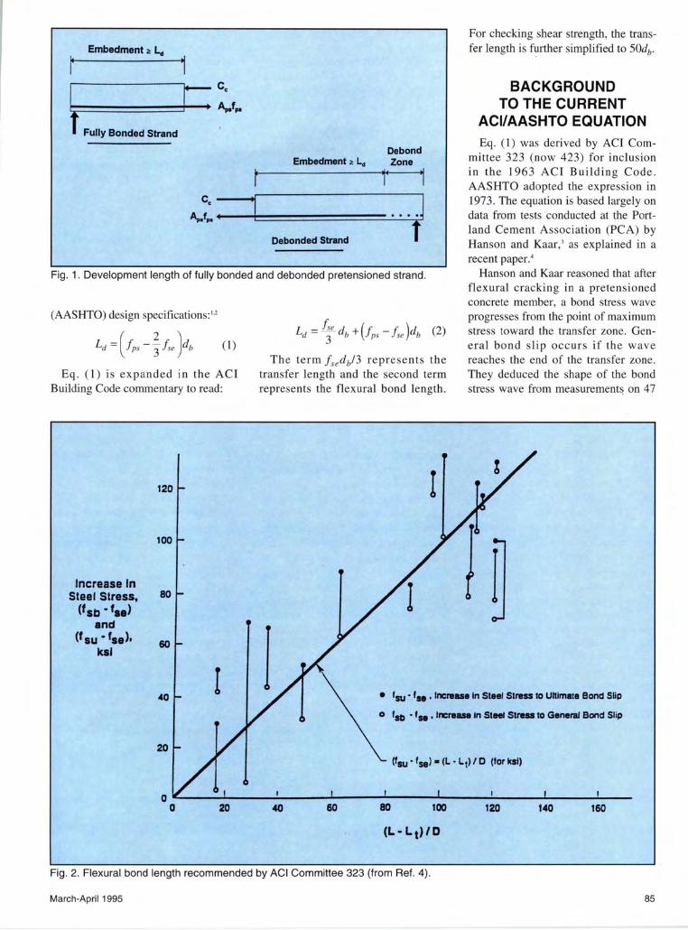
Fig. 2. Flexural bond length recommended by ACI Committee 323 (from Ref. 4).
March-Apri l1995 85
pretensioned rectangular beams. Using a lower limiting curve of local bond stresses, Hanson and Kaar calculated the embedment length necessary to develop the breaking strength of Grade 250 strands of 1
/4, 3/8, and 1h in. (6.4,
9.5, and 12.7 mm) diameters. Based on a reappraisal of Hanson
and Kaar's data, ACI Committee 323 chose a less conservative expression for the flexural bond length. Data considered by the committee, plotted in Fig. 2, show the increase in strand stress from the effective prestress, fse, to failure stress, fps• in terms of strand embedment and diameter. Open circles represent the increase in strand stress at first slip (general bond failure) and solid circles represent the increase in stress at ultimate. General bond slip corresponds to the first measurable slip at the free, unstressed end of the strand. After general bond slip, the helical shape of the wires provides mechanical resistance, which permits an increase in strand stress with additional strand slip. At ultimate bond stress, the strand slips with no further increase in stress. An equation to represent a "reasonable mean for points representing general bond slip," and deemed "not overly conservative at larger embedments," was recommended by the committee.'
Though the committee's intent was to represent the mean to points corresponding to general bond failure, it is apparent from Fig. 2 that the expression is unconservative for long embedments (i.e., Lb/db greater than about 80). Seven of the 10 specimens with Lb/db greater than 80 experienced general bond slip at lower stresses than calculated by the committee's equation. For one-half of the specimens in this region, the expression is unconservative with respect to ultimate bond failure. Most pretensioned concrete members designed today fall into this region [i.e., stress increases more than 80 ksi (552 MPa) from effective to design stress].
Eq. (1) was adopted for the 1963 ACI Building Code, which introduced strength design as an alternative to working stress design for structural concrete. At that time, bond and anchorage of reinforcement were treated by limiting calculated bond stresses
86
in a member. In subsequent ACI codes, allowable bond stresses were replaced by development length criteria. In the current ACI Code, development of reinforcement is treated in Chapter 12, "Development and Splices of Reinforcement."
A statement from the Commentary to Section 12.0 of the ACI Building Code is worth noting: "The strength reduction factor 1/J is not used in this chapter. The basic development lengths !db already include an allowance for understrength" (see Ref. 1, p. R-171). This statement is true for reinforcing bars, for which the code equations give development lengths about 15 percent longer than predicted from experimental results. A similar margin of safety is not provided for prestressing strand development lengths.
Concerns with the Current Expression
With the exception of cantilevers and short span members, strand development seldom governs the design of pretensioned concrete members. Nevertheless, several bond-related failures of pretensioned members have been reported since adoption of the current criteria. Martin and Scott describe the failure of a pretensioned member that collapsed under construction loads.5 A similar member was load tested and failed in bond at 85 percent of its expected capacity. Martin and Scott called attention to the lack of conservatism in the current criteria and recommended adoption of criteria to match the Hanson and Kaar data. They derived curves of best fit for 1/4, 3/8, and 1/z in. (6.3, 9.5 and 12.7 mm) strands consistent with Hanson and Kaar's results.
Zia and Mostafa also reported a bond-related failure in a pretensioned concrete beam. 6 In this case, the beam did not collapse, but sagged excessively with about 3/8 in. (9.5 mm) strand slip. They recommended the following more conservative equation for strand development length: 7
Ld = 1. 5 ~: db - 4. 6 + 1.25(!ps - fse )db Jet
(3)
Tests conducted in 1986 at North Carolina State University (NCSU) found development lengths for uncoated pretensioned strands that were significantly longer than predicted by Eq. (l).s
Pretensioning strand in use when the Hanson and Kaar tests were performed was stress-relieved Grade 250 strand with a specified tensile strength of 250 ksi (1.7 GPa). In current practice, Grade 270 strand with a higher tensile strength, 270 ksi (1.86 GPa), and larger cross-sectional area is used. Low-relaxation strand with higher yield stress has replaced stressrelieved strand for new construction. These improvements allow higher pretensioning stresses and larger strand sizes than those tested by Hanson and Kaar.
The longer development lengths measured in the NCSU study and the higher pretensioning stresses in current practice prompted the Federal Highway Administration (FHW A) to question the current ACIIAASHTO expression for development length. In October 1988, the FHW A issued a memorandum that imposed the following restrictions on seven-wire strands in bridge applications:9
1. The use of 0.6 in. (15.2 mm) diameter strand in a pretensioned application shall not be allowed.
2. Minimum strand spacing (centerto-center) will be four times the nominal strand diameter.
3. Development length for all strand sizes up to and including 9h6 in. (14.3 mm) shall be determined as 1.6 times AASHTO Eq. (9-32).
4. Where strand is debonded (blanketed) at the end of a member and tension at service load is allowed in the precompressed tensile zone, the development length shall be determined as 2.0 times AASHTO Eq. (9-32), as currently required by AASHTO Article 9.27.3.
Recent Research
The FHW A memorandum created problems for the prestressed concrete industry. In some cases, designs needed revisions to conform to the interim criteria, stock precast elements became obsolete, pile caps had to be
PCI JOURNAL
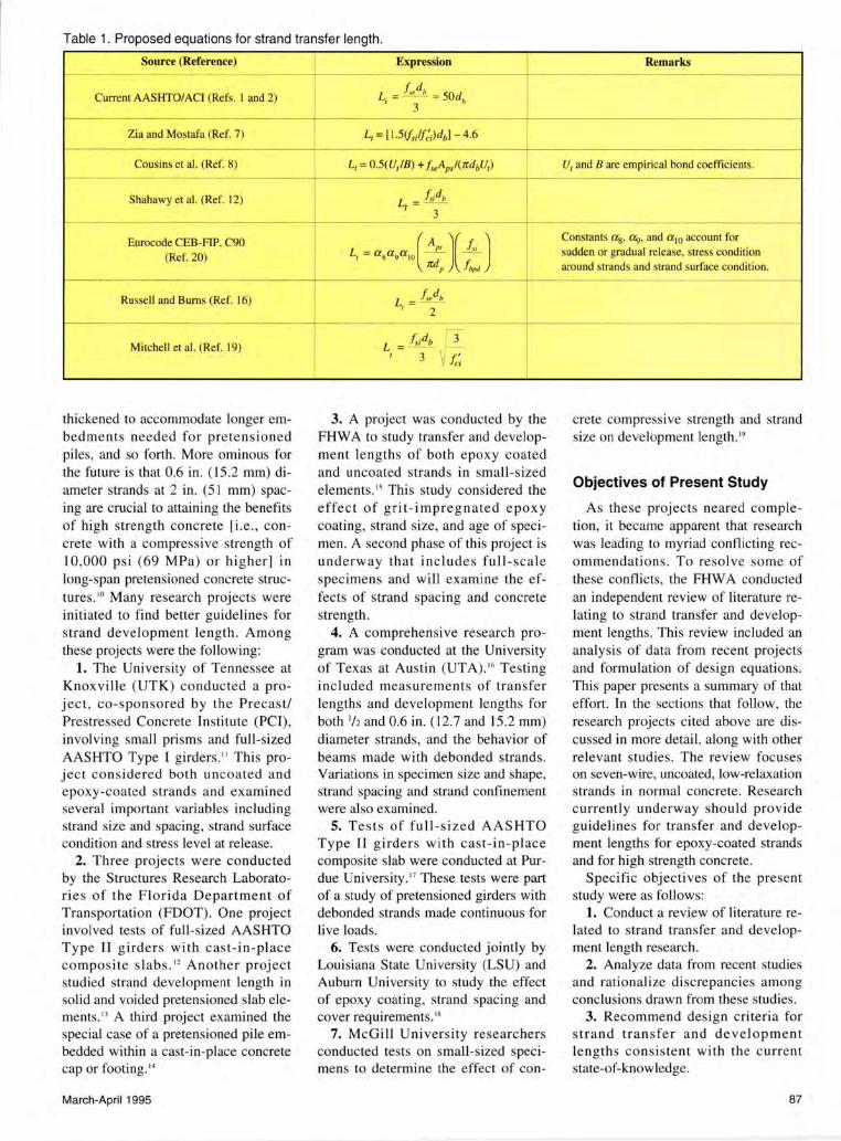
Table 1. Proposed equations for strand transfer length.
Source (Reference) f---------- ---
Current AASHTO/ACI (Refs. I and 2)
Zia and Mostafa (Ref. 7)
Cousins et al. (Ref. 8) - - ~-
Shahawy et al. (Ref. 12)
Eurocode CEB-FIP. C90 (Ref. 20)
-- -- ---
Russe ll and Burns (Ref. 16)
- --
Mitchell et al. (Ref. 19)
thickened to accommodate longer embedments needed for pretensioned piles, and so forth. More ominous for the future is that 0.6 in. (15.2 nun) diameter strands at 2 in. (51 mm) spacing are crucial to attaining the benefits of high strength concrete [i.e., concrete with a compressive strength of 10,000 psi (69 MPa) or higher] in long-span pretensioned concrete structures. '0 Many research projects were initiated to find better guidelines for strand development length. Among these projects were the following:
1. The University of Tennessee at Knoxville (UTK) conducted a project, co-sponsored by the Precast/ Prestressed Concrete Institute (PCI), involving small prisms and full-sized AASHTO Type I girders. " This project considered both uncoated and epoxy-coated strands and examined several important variables including strand size and spacing, strand surface condition and stress level at release.
2. Three projects were conducted by the Structures Research Laboratories of the Florida Department of Transportation (FDOT). One project involved tests of full-sized AASHTO Type II girders with cast-in-place composite slabs .12 Another project studied strand development length in solid and voided pretensioned slab elements. " A third project examined the special case of a pretensioned pile embedded within a cast-in-place concrete cap or footing .••
March-April 1995
Expression ,• Remarks e
l --
L = / ,.db ~ 50dh I ' 3 - -~
L1 = [ I .5(/,;f/;;)db] - 4.6 ---
I ~
1
L1 = O.S(UrfB ) + J, Apsi(TrdbU1) U1 and B are empirical bond coeffi cients. ---- - -
L - f ,,db I -
3 - -- -
I L ( AP, )( !,, ) l_ Coo""" a,, a,, ""' aw "=""' fm
' = a sa"a'o - - sudden or gradual release , stress condttion Jrd ,, !,,,}(, around strands and strand surface co~dttton ~
-- --
L, = / , db
2 ~-
!,;db 3 L = -
I 3 ~ J;;
3. A project was conducted by the FHW A to study tiansfer and development lengths of both epoxy coated and uncoated strands in small-sized elements. " This study considered the effect of grit-impregnated epoxy coating, strand size, and age of specimen. A second phase of this project is underway that includes full-scale specimens and will examine the effects of strand spacing and concrete strength.
4. A comprehensive research program was conducted at the University of Texas at Austin (UT A).'6 Testing included measurements of transfer lengths and development lengths for both 'hand 0.6 in. (12.7 and 15.2 nun) diameter strands, and the behavior of beams made with debonded strands. Variations in specimen size and shape, strand spacing and strand confinement were also examined.
5. Tests of fu ll-sized AASHTO Type II girders with cast-in-place composite slab were conducted at Purdue University .17 These tests were part of a study of pretensioned girders with debonded strands made continuous for live loads.
6. Tests were conducted jointly by Louisiana State University (LSU) and Auburn University to study the effect of epoxy coating, strand spacing and cover requirements.' 8
7. McGill University researchers conducted tests on small-sized specimens to determine the effect of con-
" .-
11
crete compressive strength and strand size on development length. '9
Objectives of Present Study
As these projects neared completion, it became apparent that research was leading to myriad conflicting recommendations. To resolve some of these conflicts, the FHW A conducted an independent review of literature relating to strand transfer and development lengths. This review inc luded an analysis of data from recent projects and formulation of design equations. This paper presents a summary of that effort. In the sections that follow, the research projects cited above are discussed in more detail , along with other relevant studies. The review focuses on seven-wire, uncoated, low-relaxation strands in normal concrete. Research currently underway should provide guidelines for transfer and development lengths for epoxy-coated strands and for high strength concrete.
Specific objectives of the present study were as follows:
1. Conduct a review of literature related to strand transfer and development length research.
2. Analyze data from recent studies and rationalize discrepancies among conclusions drawn from these studies.
3. Recommend design criteria for strand transfer and development lengths consistent with the current state-of-knowledge.
87
TRANSFER OF PRESTRESS
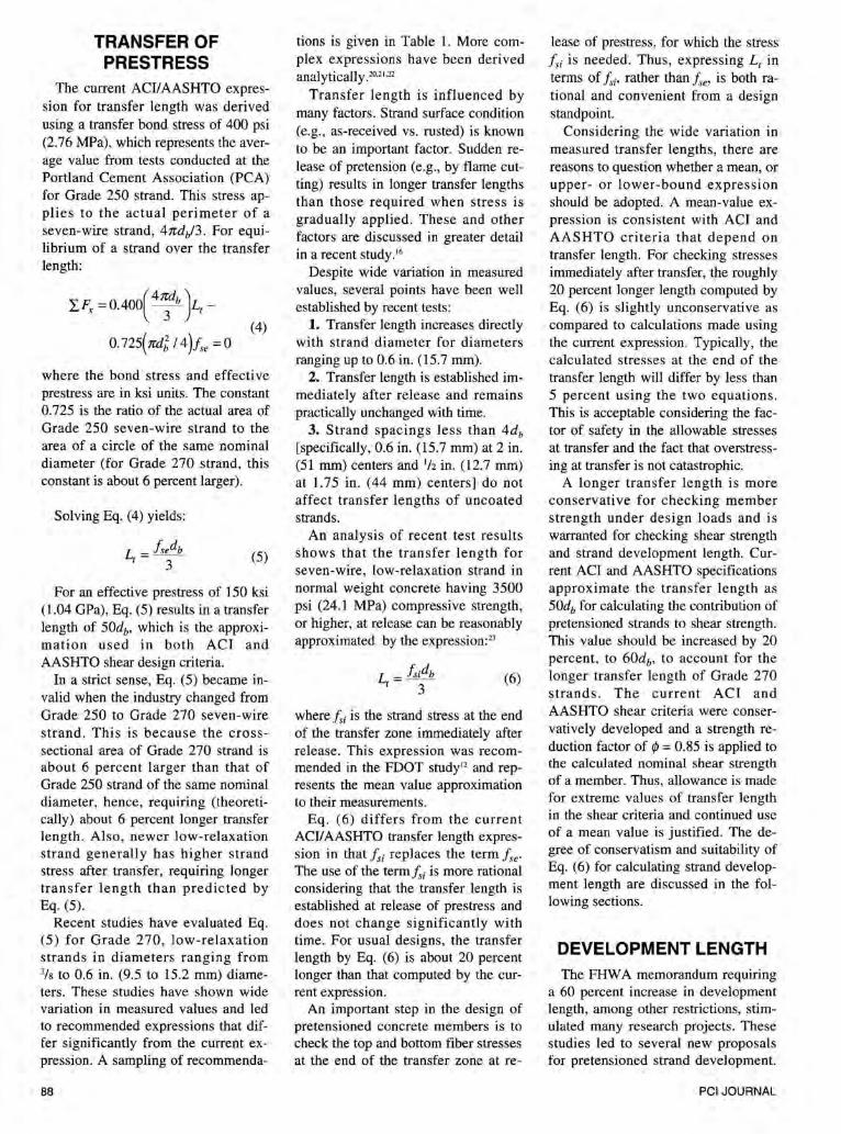
The current ACI/AASHTO expression for transfer length was derived using a transfer bond stress of 400 psi (2.76 MPa), which represents the average value from tests conducted at the Portland Cement Association (PCA) for Grade 250 strand. This stress applies to the actual perimeter of a seven-wire strand, 4ndJ3. For equilibrium of a strand over the transfer length:
L.Fx = 0.4oo( 4~b )L1 -
0. 725( ndt I 4 )fse = 0 (4)
where the bond stress and effective prestress are in ksi units. The constant 0. 725 is the ratio of the actual area of Grade 250 seven-wire strand to the area of a circle of the same nominal diameter (for Grade 270 strand, this constant is about 6 percent larger).
Solving Eq. (4) yields:
L = fsedb I 3 (5)
For an effective prestress of 150 ksi (1.04 GPa), Eq. (5) results in a transfer length of 50db, which is the approximation used in both ACI and AASHTO shear design criteria.
In a strict sense, Eq. (5) became invalid when the industry changed from Grade 250 to Grade 270 seven-wire strand. This is because the crosssectional area of Grade 270 strand is about 6 percent larger than that of Grade 250 strand of the same nominal diameter, hence, requiring (theoretically) about 6 percent longer transfer length. Also, newer low-relaxation strand generally has higher strand stress after transfer, requiring longer transfer length than predicted by Eq. (5).
Recent studies have evaluated Eq. (5) for Grade 270, low-relaxation strands in diameters ranging from 3/s to 0.6 in. (9.5 to 15.2 mm) diameters. These studies have shown wide variation in measured values and led to recommended expressions that differ significantly from the current expression. A sampling of recommenda-
88
tions is given in Table 1. More complex expressions have been derived analytically. 20
•2
'·22
Transfer length is influenced by many factors. Strand surface condition (e.g., as-received vs. rusted) is known to be an important factor. Sudden release of pretension (e.g., by flame cutting) results in longer transfer lengths than those required when stress is gradually applied . These and other factors are discussed in greater detail in a recent study.'6
Despite wide variation in measured values, several points have been well established by recent tests:
1. Transfer length increases directly with strand diameter for diameters ranging up to 0.6 in. (15.7 mm).
2. Transfer length is established immediately after release and remains practically unchanged with time.
3. Strand spacings less than 4db [specifically, 0.6 in. (15.7 mm) at 2 in. (51 mm) centers and 1/z in. (12.7 mm) at 1.75 in. (44 mm) centers] do not affect transfer lengths of uncoated strands.
An analysis of recent test results shows that the transfer length for seven-wire, low-relaxation strand in normal weight concrete having 3500 psi (24.1 MPa) compressive strength, or higher, at release can be reasonably approximated by the expression: 21
L = fs;db I 3 (6)
where /s; is the strand stress at the end of the transfer zone immediately after release. This expression was recommended in the FDOT study 12 and represents the mean value approximation to their measurements.
Eq . (6) differs from the current ACI/ AASHTO transfer length expression in that fsi replaces the term fse· The use of the term /s; is more rational considering that the transfer length is established at release of prestress and does not change significantly with time. For usual designs, the transfer length by Eq. (6) is about 20 percent longer than that computed by the current expression.
An important step in the design of pretensioned concrete members is to check the top and bottom fiber stresses at the end of the transfer zone at re-
lease of prestress, for which the stress fsi is needed. Thus, expressing L1 in terms of fsi• rather than fse, is both rational and convenient from a design standpoint.
Considering the wide variation in measured transfer lengths, there are reasons to question whether a mean, or upper- or lower-bound expression should be adopted. A mean-value expression is consistent with ACI and AASHTO criteria that depend on transfer length. For checking stresses immediately after transfer, the roughly 20 percent longer length computed by Eq. (6) is slightly unconservative as compared to calculations made using the current expression. Typically, the calculated stresses at the end of the transfer length will differ by less than 5 percent using the two equations . This is acceptable considering the factor of safety in the allowable stresses at transfer and the fact that overstressing at transfer is not catastrophic.
A longer transfer length is more conservative for checking member strength under design loads and is warranted for checking shear strength and strand development length. Current ACI and AASHTO specifications approximate the transfer length as 50db for calculating the contribution of pretensioned strands to shear strength. This value should be increased by 20 percent, to 60db, to account for the longer transfer length of Grade 270 strands. The current ACI and AASHTO shear criteria were conservatively developed and a strength reduction factor of rp = 0.85 is applied to the calculated nominal shear strength of a member. Thus, allowance is made for extreme values of transfer length in the shear criteria and continued use of a mean value is justified. The degree of conservatism and suitability of Eq. (6) for calculating strand development length are discussed in the following sections.
DEVELOPMENT LENGTH The FHW A memorandum requiring
a 60 percent increase in development length, among other restrictions, stimulated many research projects. These studies led to several new proposals for pretensioned strand development.
PCI JOURNAL
Development lengths calculated by different proposals for the same pretensioned member vary widely (typically, the highest computed value is more than double the lowest, as shown by the example in Appendix A). One study has recommended eliminating the strand development length concept and replacing it with crack prevention criteria. '6
In the following sections, several recent proposals for strand development are discussed and an attempt is made to reconcile some of the differences among the proposals. A recommendation is made to adopt a more conservative expression for development length to reflect current code philosophy and probable member behavior.
UTK Proposal for Development Length
Based on tests of 20 full-sized AASHTO Type II girders, researchers at UTK proposed the following development length equation:"
The UTK study targeted many important variables related to strand development. Unfortunately, there are reasons to question whether the UTK data justify the recommended 50 percent increase in the flexural bond length. This recommendation is based on the average bond strength at failure for the 20 specimens, which is a function of the design stress and effective prestress at the time of test. Effective prestresses reported in the UTK study were determined from strain gauge readings and are generally unrealistic.
The average effective prestress immediately after transfer reported for the UTK specimens is 186 ksi (1.28 GPa), which is reasonable considering that strands were pretensioned to 203 ksi (1.4 GPa) and elastic shortening losses average about 15 ksi (104 MPa) for the specimens. But the average effective prestress for the same specimens at the time development length tests were performed (i.e., several months later) was reported to be 193 ksi (1.33 GPa}, an increase from the stress immediately after transfer. More likely, creep, shrinkage and relaxation
March-April 1995
reduced the prestress from an average 186 ksi ( 1.28 GPa) to about 165 ksi ( 1.14 GPa) at the time development length tests were performed.
No explanation is given in the UTK report for this unusual behavior. However, the researchers note in an early version of the project reporf• that, " ... reliability of the resistance strain gauges during the construction phase was questionable. At best, no more than half of the installed gauges provided test results after transfer. Also, correlating the output strains with theoretical strains at the failing load provided questionable results" (see Ref. 24, p. 53).
Erroneously large effective prestress in the specimens Jed to the conclusion that average flexural bond stresses were lower than predicted by the current expression, hence, requiring a 50 percent longer flexural bond length. (Note that the analysis on which the final UTK recommendation was made fixed this increase more precisely as 42 percent) .24 Assuming a design stress of 250 ksi (1.73 GPa), which is close to the average reported for specimens that failed in flexure and to the value obtained by strain compatibility analysis, the consequence of erroneously large effective prestress can be shown:
. (ips - fse L.el Rat1o= Y
(ips - fse t eported (8}
= 250 - 165 = 1. 5 250-193
Thus, to justify a 50 percent increase in flexural bond length requires that effective prestress increases with time, which is unlikely. Assuming effective prestress diminished to about 165 ksi (1.14 GPa) when development length tests were performed implies that the current ACII AASHTO equation is adequate for the UTK specimens.
The UTK development length tests were performed with the specimens supported on concrete-filled structural steel tubes. Friction at these supports created an arching action that enhanced resistance to the applied loads. A precise analysis of this effect is impossible. An analysis by the UTK researchers gave horizontal reactions
ranging from 10.6 to 27.4 kips (47.2 to 122 kN) at failure. 25 This analysis was based on a theory that the concrete near the load point was strengthened by confinement supplied by the loading plate. Confinement was assumed to increase the compressive strength to more than twice the measured uniaxial strength of some specimens. Calculated strand stresses by this analysis were generally larger than the guaranteed ultimate strength and considerably larger than values tabulated in the final report.
Given the uncertainties of the actual strand stresses in the UTK specimens, a modification to the development equation based on the UTK data is unjustified.
FOOT Proposal for Development Length
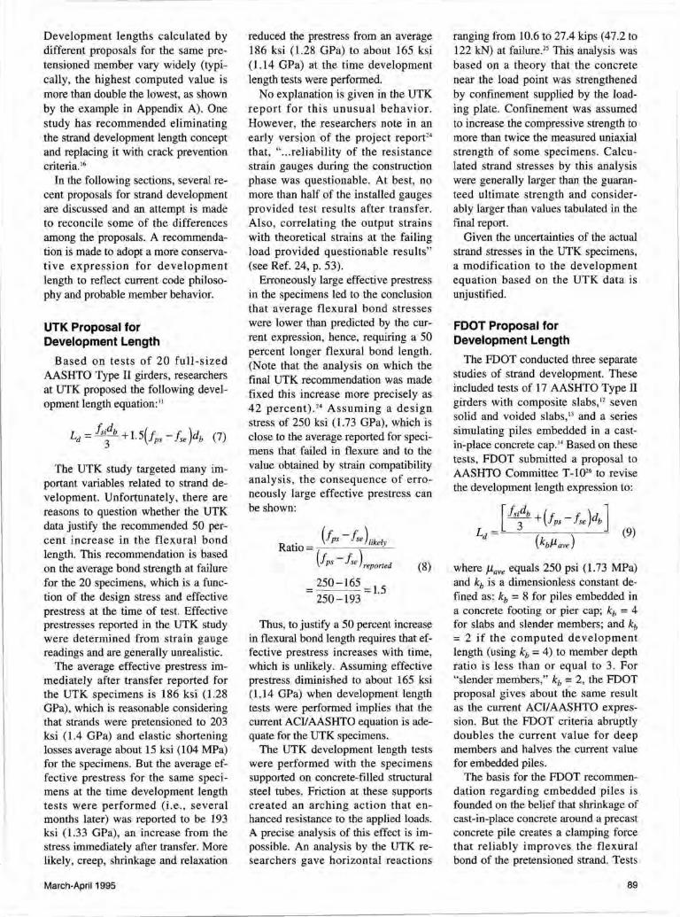
The FDOT conducted three separate studies of strand development. These included tests of 17 AASHTO Type II girders with composite slabs, 12 seven solid and voided slabs, 13 and a series simulating piles embedded in a castin-place concrete cap.'4 Based on these tests, FDOT submitted a proposal to AASHTO Committee T-1026 to revise the development length expression to:
where llave equals 250 psi (1.73 MPa) and kb is a dimensionless constant defined as: kb = 8 for piles embedded in a concrete footing or pier cap; kb = 4 for slabs and slender members; and kb = 2 if the computed development length (using kb = 4) to member depth ratio is less than or equal to 3. For "slender members," kb = 2, the FDOT proposal gives about the same result as the current ACI/AASHTO expression. But the FDOT criteria abruptly doubles the current value for deep members and halves the current value for embedded piles.
The basis for the FDOT recommendation regarding embedded piles is founded on the belief that shrinkage of cast-in-place concrete around a precast concrete pile creates a clamping force that reliably improves the flexural bond of the pretensioned strand. Tests
89
conducted by FOOT for this application involved testing segments of a salvaged 14 x 14 in. (356 x 356 mm) pretensioned pile. The segments were loaded to failure after clamping them with a 200 kip (889 kN) force intended to simulate the effect of shrinkage in surrounding concrete. There are several questionable assumptions regarding this test program:
1. The clamping force was determined from strains measured within a 42 x 54 x 48 in. (l.l x 1.4 x 1.2 m) concrete mass surrounding a precast concrete section. Large strains (more than 300 microstrains) were recorded after one day near the middle of the mass concrete and initially attributed by the researchers to drying shrinkage in the concrete. These strains are orders of magnitude larger than can realistically be attributed to concrete shrinkage. More recently, the researchers have acknowledged that the initial strain readings were caused by temperature rise.27
But they maintain that after two weeks, the concrete temperature returned to ambient and that subsequent strains were caused by shrinkage. Considering the disparity between tensile and compressive strains associated with this explanation, it appears unlikely that such large strains were caused by drying shrinkage.
2. A stress distribution within the mass concrete was formulated by simply multiplying principal strains by an assumed concrete modulus of 3600 ksi (24.8 GPa). This overlooks the fact that creep significantly alleviates internal stresses caused by confined shrinkage in concrete. The resulting stress distribution bears no resemblance to a distribution caused by drying shrinkage. In reality, restrained drying shrinkage in mass concrete results in tensile stresses near the surface, not compressive clamping stress, as used in the FOOT tests.
3. Specimens cut from an existing pile section are likely to have significantly shorter transfer lengths than a typical pretensioned pile. The transfer length in a pretensioned pile is more than one-half the FDOT' s proposed development length, leaving only about a 24 in. (610 mm) flexural bond length.
FDOT's proposal to adopt the ex-
90
pression fs;db/3 for transfer length has merit. However, abruptly doubling the development length based on the spanto-depth ratio or halving the development length for embedded piles is not justified by the FDOT research.
Purdue University Tests
Tests performed at Purdue University involved full-sized AASHTO bridge girders and box beams with both debonded and fully bonded strand patterns. 17 Girders were made composite with a cast-in-place slab. The fully bonded specimens were loaded to failure with embedments exceeding the development length calculated by the current ACI/ AASHTO equation. For embedments of about 1.2 times the calculated development length, the specimens failed at two-thirds to threequarters of their predicted capacities. Only with an embedment of 1.8 times the calculated development length was the full capacity achieved. This led to the conclusion:
"The flexural and shear design of both bonded and debonded pretensioned 1-beams, where the flexural capacity controls, based on current ACII AASHTO design provisions would be adequate provided that the fully bonded strands in the member have anchorage length of at least 1. 7 Ld. This recommendation is based on the results of the fully bonded beam in Specimen Set 3 as a lower bound. This value of 1. 7 Ld is also in agreement with the finding in the FDOT study." (see Ref. 17, p. 65.)
McGill University Proposal
Based on tests of 22 single-strand rectangular specimens, researchers at McGill University expressed strand development length as a function of concrete compressive strength. 19 The expression is similar in format to the current ACIIAASHTO expression except that the transfer length and flexural bond length are multiplied by the terms involving concrete compressive strength, and fs; replaces fse in the transfer length. This results in the equation:
(10)
This expression agrees well with data from the McGill tests but does not compare well with the data from other recent studies. 23 Some of the difference may result from the gradual release method employed in the McGill tests, as compared to sudden release in most other studies. Also, the strand surface condition in the McGill study was described as slightly rusted, which is known to improve bond.
The McGill tests provide clear evidence that strand bond is better in high strength concrete members than in similar members of normal concrete. Research in progress will provide a better data base to evaluate the McGill expression. Until more data are available, the McGill University equation is not recommended for design purposes.
Strand Development by UTA Criteria
The UTA study concluded that seven-wire pretensioned strands could be developed by preventing cracks within the transfer zone. Instead of checking strand embedment against a calculated development length, design guidelines were developed to prevent concrete cracking in the debond/transfer zones of girders. 16 For this purpose, the UTA study recommended an expression for transfer length, f se db/2, which gives transfer lengths that are 50 percent longer than those calculated by the current ACIIAASHTO expression. The UTA strand development approach is summarized in the following general conclusion:
" ... to prevent anchorage failures, beams should be designed so that no concrete cracks will propagate through the transfer zone of a pretensioned strand. This observation is comprehensive for all sizes of pretensioned strand, for all pretensioned applications, and for both fully bonded and debonded strands." (see Ref. 16, p. 209)
PCI JOURNAL
100
I II Web Sheer. CliO !no and End Slip
~ h / JBon ~Falkn I
I /
I - Deflection
v v _._ EnciSUp
0 0 .6 1.1 2
0 .1
OA 'E' c;.
< 0.3 I 0.2 i
(/)
! 0.1
0
80
g 80
~ 40
20
0
Deflection (In)
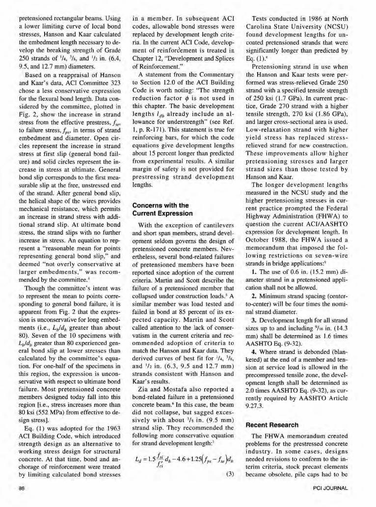
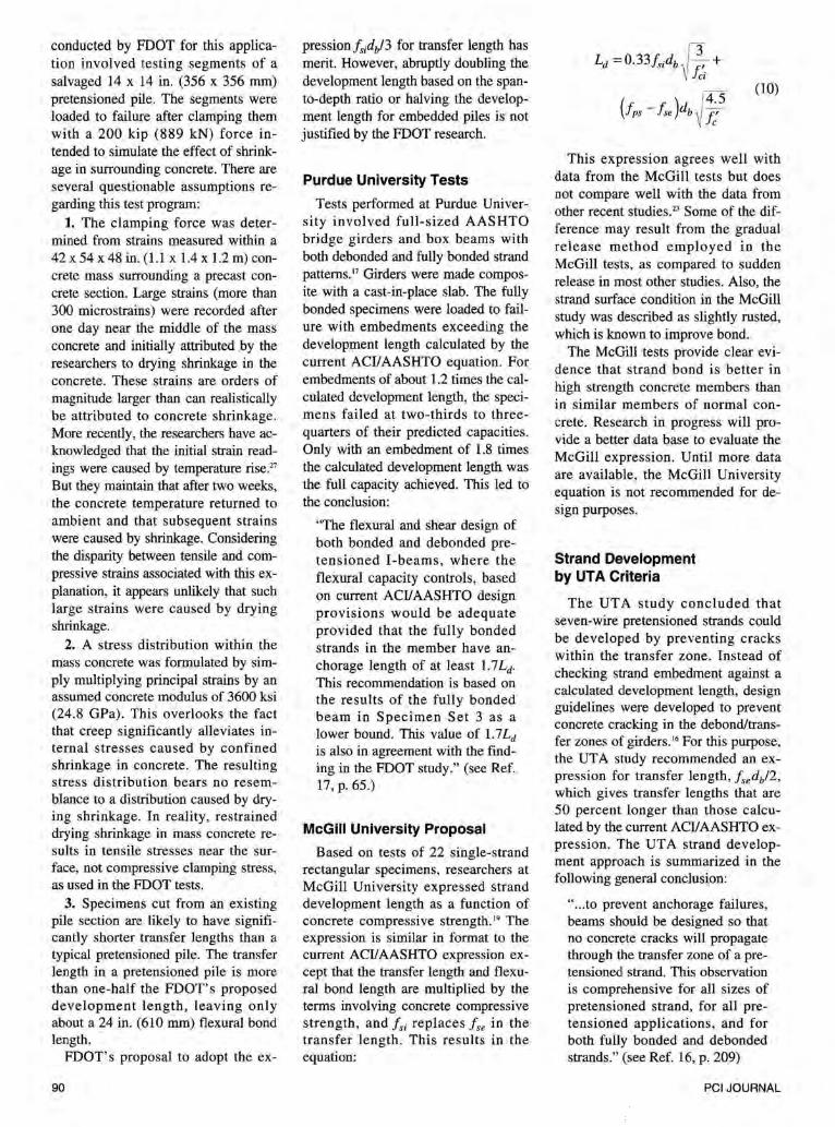
Fig. 3. Load and end slip vs. deflection for a UTA specimen (from Ref. 28).
For members containing debonded strands, the importance of preventing cracks within the debond/transfer zone under design loading was well established by the UTA tests. But the generality of this criterion for all pretensioned applications is questionable. That it is not generally applicable is shown by several specimens from the Hanson and Kaar tests3 that failed in bond with ultimate moments less than predicted and without cracks within their transfer lengths.
As one example, Specimen 3-10 from the Hanson and Kaar study can be cited. This specimen was reported to have failed in general bond at only 77 percent of its full nominal moment strength and to have attained only 90 percent of its nominal strength at ultimate. The specimen had a reported transfer length of 26 in. (660 rnm) and a cracking moment of 467 kip-in. (5.3 MN-m) . The closest probable crack was about 5 ft (1.5 m) from the member end, which is roughly twice the reported transfer length. Several other exceptions to the UTA general conclusion can be found among the specimens tested by Hanson and Kaar.
The UTA program included development length tests for 19 I -shaped beams resembling AASHTO-type composite girders. These specimens frequently showed initial bond slip occurring coincident with web-shear cracking. The UTA researchers observe that, " ... this and other research consistently demonstrate web shear cracking to precipitate anchorage failures" (see Ref. 16, p. 51) . Behavior
March-April 1995
depicted in Fig. 3, however, casts doubt on whether web-shear cracking initiated strand slip or vice-versa. This figure shows load-deflection and strand end slip measurements from a UTA test.28
For this specimen, initial strand slip occurred at an applied load of about 70 kips (311 kN) [i.e., 0.7 in. (18 rnm) midspan deflection] but web-shear cracking was not observed until about 77 kips (343 kN) [i.e., 0.9 in . (23 rnm) deflection]. The initial recorded end slip is about O.D15 in. (0.4 mm). If this slip occurred over a distance of 40 in. (1.0 m) , which is only hypothetical, and resulted in a uniform reduction in bond stress over this length, the corresponding loss of prestress would be about 20 ksi (138 MPa). This sudden loss of prestress causes a sudden increase in principal tensile stresses in the web and this could lead to subsequent web-shear cracking.
Other recent studies offer conflicting opinions about whether bond slip results in a shear failure or vice-versa. The UTK report, for example, states, "Some slight slippage of the strands during static testing did not significantly reduce the beam flexural strength, but it did make the beams more susceptible to shear failure ... " (see Ref. 24, p. 67) . Conversely, the FDOT study for composite AASHTOtype girders concludes , "The results indicate a direct interaction between shear and bond with the initial slip occurring immediately or shortly after the appearance of the first shear crack." (see Ref. 26, p. 89).
The best documented evidence found to explain the interaction between shear and bond is Fig. 3, which gives a strong indication that general bond slip occurred prior to sudden shear failure. No matter whether the failure mode is shear/bond or bond/shear, the failure is sudden and undesirable and should be prevented by the adoption of conservative criteria.
The behavior of several rectangular specimens in the UTA study also creates doubt as to whether this crack prevention approach is a practical way to ensure strand development. Specimens FR350-l and -2, containing 112 in. (12.7 mm) diameter strands, both failed with significant amounts of strand slip. Though transfer lengths were not measured for these specimens, they were estimated to be about twice as long as usual [52 to 64 in . (1.32 to 1.6 m) based on end slips at transfer] .
On this basis, the failures were rationalized to satisfy the UTA failure criterion. But a designer must rely on calculations and the UTA criterion predicts that the strands in these specimens fully develop, even at embedments as short as 60 in . (1.5 m ). When te sted, Specimen FR350-l achieved only about two-thirds its full nominal moment strength with embedments of 60 and 72 in. (1.5 and 1.8 m). Specimen FR350-2 achieved 90 percent capacity with an embedment of 84 in. (2 .1 m) and reached essentially full capacity with 96 in . (2.4 m) embedment. But even at this embedment the strands slipped significantly at ultimate.
The UTA report attributes the likely cause of the poorer-than-expected bond in Specimens FR350-1 and -2 to accidental strand contamination, which led to exceptionally long transfer lengths. Extensive test data show, however, that transfer lengths vary widely, with standard deviations in most test programs on the order of ±10 in. (±254 mm). Variation is well illustrated by several full-scale specimens in the UTA study, which had significantly longer transfer lengths [up to 74 in. (1.9 m)] than laboratorycast specimens. Thus, for reasonable assurance that flexural cracks do not intersect the transfer zone, an ex-
91
Wu= 12 kif
Elevation
fS8= 155 ksi
L =5" b
b= 16"
0 Section
Data;_ h = 16" dp= 14" f' = 5000 psi c . 2 Ap?0.30~1n fse= 155 ks1 Mcf 64.4 kft ctM if 80.9 kft
ub = 1500 psi ,ave
Flexural Bond Length
Note: 1 1n • 25.4 mm; 1 kip • 1000 lb • 6.9 kN
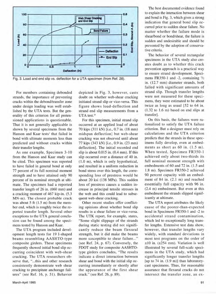
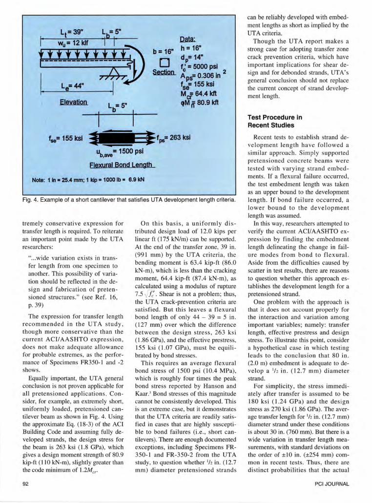
Fig. 4. Example of a short canti lever that satisfies UTA development length criteria.
tremely conservative expression for transfer length is required. To reiterate an important point made by the UTA researchers:
" .. . wide variation exists in transfer length from one specimen to another. This possibility of variation should be reflected in the design and fabrication of pretensioned structures." (see Ref. 16, p. 39)
The expression for transfer length recommended in the UTA study, though more conservative than the current ACI/AASHTO expression, does not make adequate allowance for probable extremes, as the performance of Specimens FR350-1 and -2 shows.
Equally important, the UTA general conclusion is not proven applicable for all pretensioned applications. Consider, for example, an extremely short, uniformly loaded, pretensioned cantilever beam as shown in Fig. 4. Using the approximate Eq. (18-3) of the ACI Building Code and assuming fully developed strands, the design stress for the beam is 263 ksi (1.8 GPa), which gives a design moment strength of 80.9 kip-ft (110 kN-m), slightly greater than the code minimum of l.2Mcr
92
On this basis, a uniformly distributed design load of 12.0 kips per linear ft (175 kN/m) can be supported. At the end of the transfer zone, 39 in. (991 mm) by the UTA criteria, the bending moment is 63.4 kip-ft (86.0 kN-m), which is less than the cracking moment, 64.4 kip-ft (87.4 kN-m), as calculated using a modulus of rupture 7.5 {1: . Shear is not a problem; thus, the UTA crack-prevention criteria are satisfied. But this leaves a flexural bond length of only 44 - 39 = 5 in. (127 mm) over which the difference between the design stress , 263 ksi (1.86 GPa), and the effective prestress, 155 ksi (1.07 GPa), must be equilibrated by bond stresses.
This requires an average flexural bond stress of 1500 psi (10.4 MPa), which is roughly four times the peak bond stress reported by Hanson and Kaar.3 Bond stresses of this magnitude cannot be consistently developed. This is an extreme case, but it demonstrates that the UTA criteria are readily satisfied in cases that are highly susceptible to bond failures (i.e. , short cantilevers). There are enough documented exceptions, including Specimens FR-350-1 and FR-350-2 from the UTA study, to question whether 1h in. (12.7 mm) diameter pretensioned strands
can be reliably developed with embedment lengths as short as implied by the UTA criteria.
Though the UTA report makes a strong case for adopting transfer zone crack prevention criteria, which have important implications for shear design and for de bonded strands, UTA's general conclusion should not replace the current concept of strand development length.
Test Procedure in Recent Studies
Recent tests to establish strand development length have followed a similar approach. Simply supported pretensioned concrete beams were tested with varying strand embedments. If a flexural failure occurred, the test embedment length was taken as an upper bound to the development length. If bond failure occurred, a lower bound to the development length was assumed.
In this way, researchers attempted to verify the current ACI/AASHTO expression by finding the embedment length delineating the change in failure modes from bond to flexural. Aside from the difficulties caused by scatter in test results, there are reasons to question whether this approach establishes the development length for a pretensioned strand.
One problem with the approach is that it does not account properly for the interaction and variation among important variables; namely: transfer length, effective prestress and design stress. To illustrate this point, consider a hypothetical case in which testing leads to the conclusion that 80 in. (2.0 m) embedment is adequate to develop a 112 in . (12 .7 mm) diameter strand.
For simplicity, the stress immediately after transfer is assumed to be 180 ksi ( 1.24 GPa) and the design stress as 270 ksi (1.86 GPa). The average transfer length for 1h in. (12.7 mm) diameter strand under these conditions is about 30 in. (760 mm). But there is a wide variation in transfer length measurements, with standard deviations on the order of ±10 in. (±254 mm) common in recent tests. Thus, there are distinct probabilities that the actual
PCI JOURNAL
transfer length for a specimen might be as short as 15 in. (380 mm) or as long as 45 in. (1.14 m). A few possible outcomes for test results are summarized in Table 2.
On the first line of Table 2, which is labeled "Good Bond," are data for a specimen with an extremely short transfer length, taken here as 15 in. (380 mm). The effective prestress at time of test is taken as relatively large at 175 ksi (1.2 GPa)(e.g., a high quality concrete specimen tested at an early age). The average transfer bond stress for this case , acting on the actual strand perimeter of 2.09 in. (74 mm), is:
180x0.153
15x2.09 = 0.88 ksi (6.1 MPa)
(11)
For a 15 in. (380 mm) transfer length, the complementary flexural bond length is (80 - 15) = 65 in. (1.65 m). The average flexural bond stress that must be developed for this case is:
- (270 -175)0.153
65x2.09
= 0.106 ksi (0. 7 MPa)
(12)
Thus, average transfer bond stress in this case is roughly eight times the average flexural bond stress and bond failure is highly unlikely. But consider the sensitivity of the average bond stresses to transfer length and effective prestress. Results for an "Average" case are listed in Line 2 of Table 2. Here, a transfer length of 30 in. (762 mm) implies poorer bond than existed for the "Good Bond" case. Further, a lower effective prestress of 150 ksi (1.04 GPa) requires that a larger force be equilibrated over a shorter flexural bond length, 50 in. (1.26 m), resulting in a much higher flexural bond stress than in the "Good Bond" case. For this case, the ratio of average transfer bond to average flexural bond stresses drops to one-third the ratio of the "Good Bond" case. But even attaining flexu-
March-April 1995
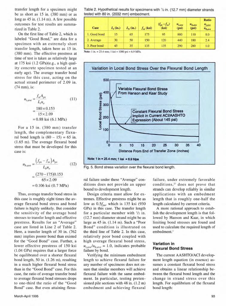
Table 2. Hypothetical results for specimens with 112 in. (12.7 mm) diameter strands tested with 80 in. (2032 mm) embedment.
I I
Ratio ifps- fse) "t,ave ub,ave "t,ave
Case L1 (in.) Lb (in.) fse (ksi) (ksi) (psi) (psi) ub,ave
I. Good bond 15 65 175 95 880 110 8.0
2. Average 30 50 ISO I 120 440 180 2.4
3. Poor bond 45 35 135 I 135 290 I 280 I
1.0
Note: I in. = 25.4 mm; I ksi = 1000 psi = 6.9 MPa.
Variation in Local Bond Stress Over the Flexural Bond Length
-400 .
! Ill
:g 300 iE -g dl200 ..
iii
Constant Flexural Bond Stress Implicit in Current ACUAASHTO Expression (About 145 psi)
g ..J 100
0~--------------------------------~ 0 5 10 15 20 25 30 35 40
Distance From End of Transfer Zone (inches)
Note: 1 In • 25.4 mm; 1 ksi • 6.9 Mpa
Fig. 5. Bond stress variation over the flexural bond length.
ral failure under these "Average" conditions does not provide an upper bound to development length.
Design criteria must allow for extremes. Effective prestress might be as low as 0.5fpu• which is 135 ksi (930 GPa) in this case. The transfer length for a particular member with 112 in. (12.7 mm) diameter strand might be as large as 45 in. (1.14 m). Such a "Poor Bond" condition is illustrated on the third line of Table 2. In this case, relatively poor bond coupled with high average flexural bond stress, U1,ave l ub,ave = 1.0, indicates probable failure by bond.
Verifying the minimum embedment length to achieve flexural failure for any number of specimens does not ensure that similar members will achieve flexural fail ure with the same embedment . In particular, testing preten sioned pile sections with 48 in. (1.2 m) embedment and achieving flexural
failure , under extremely favorable conditions, 27 does not prove that strands can develop reliably in similar applications with an embedment length that is roughly one-half the length calculated by current criteria.
A more rational approach to establish the development length is that followed by Hanson and Kaar, in which limiting bond stresses are found and used to calculate the required length of embedment. 3
Variation in Flexural Bond Stress
The current AASHTO/ACI development length equation (in essence) assumes a constant flexural bond stress and obtains a linear relationship between the flexural bond length and the change in strand stress over this length. For equilibrium of the flexural bond length:
93
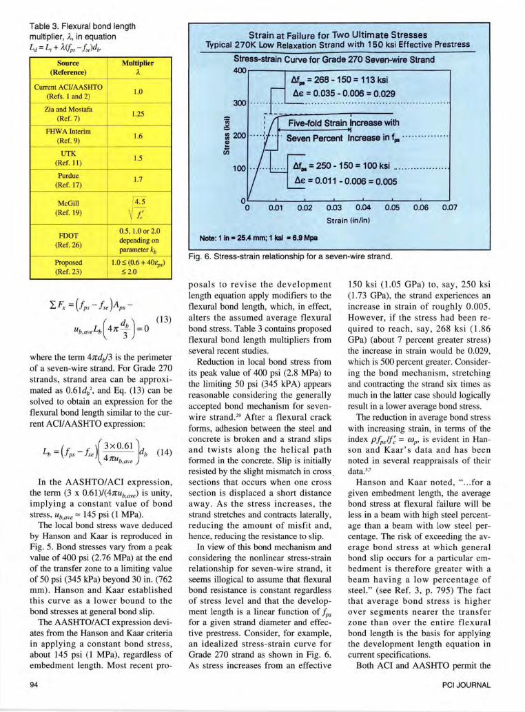
Table 3. Flexural bond length multiplier, A., in equation Ld = L, + Mfps - fs,)db.
Source Multiplier (Reference) A-
Current ACIIAASHTO 1.0
(Refs. I and 2)
Zia and Mostafa 1.25
(Ref. 7)
FHW A Interim 1.6
(Ref. 9)
UTK 1.5
(Ref. II )
Purdue 1.7 (Ref. 17)
McGill ru -
(Ref. 19) ~ !/
FOOT 0.5, 1.0 or 2.0
(Ref. 26) depending on parameter kb
Proposed 1.0 $ (0.6 + 40t:ps) (Ref. 23) $2.0
(13)
where the term 4rrdtf3 is the perimeter of a seven-wire strand. For Grade 270 strands, strand area can be approximated as 0.6ldb>, and Eq. (13) can be solved to obtain an expression for the flexural bond length similar to the current ACI/AASHTO expression:
L =(+ _+ )(3x0.61} b J ps Jse 4
b rrub,ave
(14)
In the AASHTO/ACI expression, the term (3 x 0.6l)/(4rrub,ave) is unity, implying a constant value of bond stress, ub,ave == 145 psi (1 MPa).
The local bond stress wave deduced by Hanson and Kaar is reproduced in Fig. 5. Bond stresses vary from a peak value of 400 psi (2.76 MPa) at the end of the transfer zone to a limiting value of 50 psi (345 kPa) beyond 30 in. (762 mm). Hanson and Kaar established this curve as a lower bound to the bond stresses at general bond slip.
The AASHTO/ACI expression deviates from the Hanson and Kaar criteria in applying a constant bond stress, about 145 psi (1 MPa), regardless of embedment length. Most recent pro-
94
Strain at Failure for Two Ultimate Stresses Typical 270K Low Relaxation Strand with 150 ksi Effective Prestress
Stress-strain Curve for Grade 270 Seven-wire Strand 400r-----~----------------------------·
M.- = 268 - 150 = 113 ksi
lle = 0.035 - 0.006 = 0.029 300 . .... .
OL---~----~--~~--~---~--~--~ 0 O.Ql 0.02 0.03 0.04 0.05 0.06 0.07
Strain (in/in)
Note: 1 In • 25.4 mm; 1 ksl • 6.9 Mpa
Fig. 6. Stress-strain relationship for a seven-wire strand.
posals to revise the development length equation apply modifiers to the flexural bond length, which, in effect, alters the assumed average flexural bond stress. Table 3 contains proposed flexural bond length multipliers from several recent studies.
Reduction in local bond stress from its peak value of 400 psi (2.8 MPa) to the limiting 50 psi (345 kPA) appears reasonable considering the generally accepted bond mechanism for sevenwire strand.29 After a flexural crack forms, adhesion between the steel and concrete is broken and a strand slips and twists along the helical path formed in the concrete. Slip is initially resisted by the slight mismatch in cross. sections that occurs when one cross section is displaced a short distance away. As the stress increases, the strand stretches and contracts laterally, reducing the amount of misfit and, hence, reducing the resistance to slip.
In view of this bond mechanism and considering the nonlinear stress-strain relationship for seven-wire strand, it seems illogical to assume that flexural bond resistance is constant regardless of stress level and that the development length is a linear function of /p5
for a given strand diameter and effective prestress. Consider, for example, an idealized stress-strain curve for Grade 270 strand as shown in Fig. 6. As stress increases from an effective
150 ksi (1.05 GPa) to, say, 250 ksi (1.73 GPa), the strand experiences an increase in strain of roughly 0.005. However, if the stress had been required to reach, say, 268 ksi (1.86 GPa) (about 7 percent greater stress) the increase in strain would be 0.029, which is 500 percent greater. Considering the bond mechanism, stretching and contracting the strand six times as much in the latter case should logically result in a lower average bond stress.
The reduction in average bond stress with increasing strain, in terms of the index pfp/f: = mP' is evident in Hanson and Kaar' s data and has been noted in several reappraisals of their dataY
Hanson and Kaar noted, " ... for a given embedment length, the average bond stress at flexural failure will be less in a beam with high steel percentage than a beam with low steel percentage. The risk of exceeding the average bond stress at which general bond slip occurs for a particular embedment is therefore greater with a beam having a low percentage of steel." (see Ref. 3, p. 795) The fact that average bond stress is higher over segments nearer the transfer zone than over the entire flexural bond length is the basis for applying the development length equation in current specifications.
Both ACI and AASHTO permit the
PCI JOURNAL
investigation of strand development to be limited to the critical sections nearest to each end of a member. For some members, the available length of embedment is less than that required to develop the strand to its ultimate stress, /pu- Because the average flexural bond stress is higher for shorter lengths of embedment, it is conservative to use the development length equation to solve for the maximum strand stress that can be developed for the given embedment length. This approach is used, for example, in AASHTO Eq. (9-19) to calculate the limiting strand stress for precast, prestressed deck panels.2
Failure Strains in Recent Test Specimens
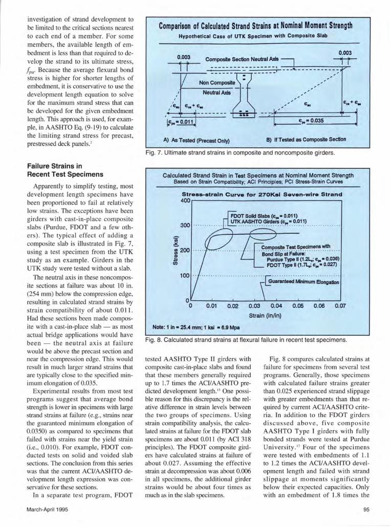
Apparently to simplify testing, most development length specimens have been proportioned to fail at relatively low strains. The exceptions have been girders with cast-in-place composite slabs (Purdue, FDOT and a few others) . The typical effect of adding a composite slab is illustrated in Fig. 7, using a test specimen from the UTK study as an example. Girders in the UTK study were tested without a slab.
The neutral axis in these noncomposite sections at failure was about 10 in. (254 mm) below the compression edge, resulting in calculated strand strains by strain compatibility of about 0.0 ll . Had these sections been made composite with a cast-in-place slab- as most actual bridge applications would have been - the neutral axis at failure would be above the precast section and near the compression edge. This would result in much larger strand strains that are typically close to the specified minimum elongation of 0.035.
Experimental results from most test programs suggest that average bond strength is lower in specimens with large strand strains at failure (e.g., strains near the guaranteed minimum elongation of 0.0350) as compared to specimens that failed with strains near the yield strain (i.e. , 0.010). For example, FDOT conducted tests on solid and voided slab sections. The conclusion from this series was that the current ACII AASHTO development length expression was conservative for these sections.
In a separate test program, FDOT
March-April 1995
Comparison of Calculated Strand Strains at Nominal Moment Strength Hypothetical Case of UTK Specimen with Composite Slab
Composite Section Neutral Axis
Neutral Axis
A) As Tested (Precast Only) B) If Tested as Composite Section ·
Fig. 7. Ultimate strand strains in composite and noncomposite girders.
Calculated Strand Strain in Test Specimens at Nominal Moment Strength Based on Strain Compatibility; ACI Principles; PCI Stress-Strain Curves
Streaa-atraln Curve for 270Kal Seven-wire Strand 400r----------------------------------,
300
Composite Test Specimens with · · ·aonci s·n"P &i "F&iiui&:· · · · · · · · · · · · · · · ·
Purdue Type II (12L.; e,.• 0.036) FOOT Type II (1 .7l.; e,. • 0.027)
0.01 0.02 0.03 0.04 0.05 0.06 0.07
Strain (in/in)
Note: 1 in • 25.4 mm; 1 ksl • 6.9 Mpa
Fig. 8. Calculated strand strains at flexural failure in recent test specimens.
tested AASHTO Type II girders with composite cast-in-place slabs and found that these members generally required up to 1.7 times the ACIIAASHTO predicted development length. 13 One possible reason for this discrepancy is the relative difference in strain levels between the two groups of specimens . Using strain compatibility analysis, the calculated strains at failure for the FDOT slab specimens are about 0.011 (by ACI 318 principles). The FDOT composite girders have calculated strains at failure of about 0.027. Assuming the effective strain at decompression was about 0.006 in all specimens, the additional girder strains would be about four times as much as in the slab specimens.
Fig. 8 compares calculated strains at failure for specimens from several test programs. Generally, those specimens with calculated failure strains greater than 0.025 experienced strand slippage with greater embedments than that required by current ACIIAASHTO criteria. In addition to the FDOT girders discussed above, five composite AASHTO Type I girders with fully bonded strands were tested at Purdue University. 17 Four of the specimens were tested with embedments of 1.1 to 1.2 times the ACI/AASHTO development length and failed with strand slippage at moments significantly below their expected capacities. Only with an embedment of 1.8 times the
95
Comparison of Calculated Development Lengths rc .. 5000 psi; rei .. 4000 psi; fsi .. 180 ksi; fse "' 180 ksi 12- by 32-in beam with varying number of 1/2-in strands
_200.---------------------· §.
-1969MSHTO
+ Current ACI/MSHTO
+ McGill Univ.
... FOOT Proposal
-UTK
-+- Zla-Moustafa
-g 50 . . .. ··· ·· · · ·· · · ·· · · · · · · · . .. · · · ·· ··· ·· · ·· · · - Martin-Scott
'Iii '3 u iii
+Purdue
•Proposed
0 0~--------------------~ 80 85 90 95 100 105 110 115 120
Stress Change, (fps- fse), (ksl) Note: 1 In • 25.4 mm; 1 kll • 8.9 Mpa
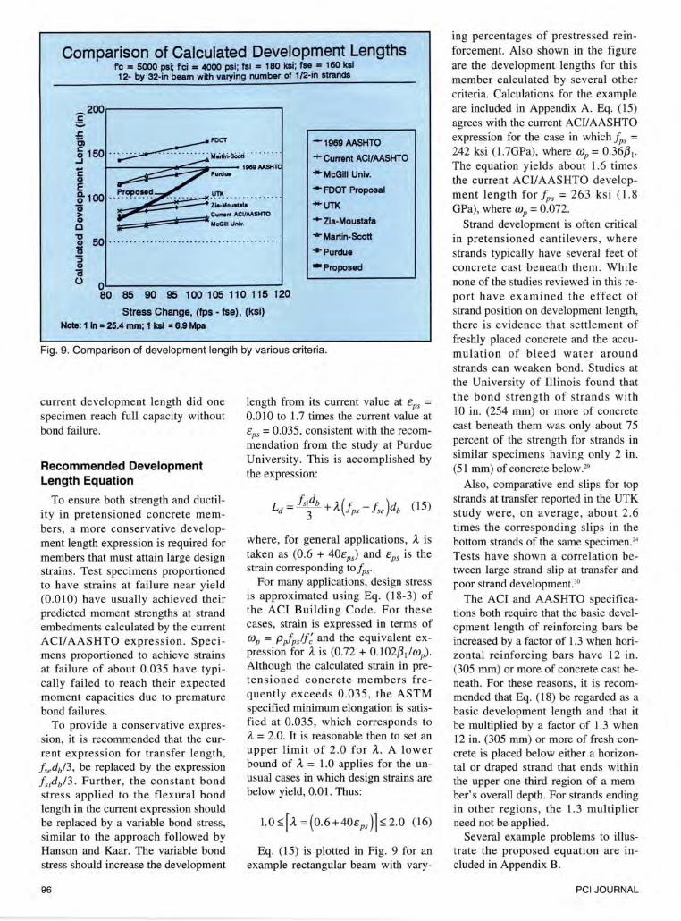
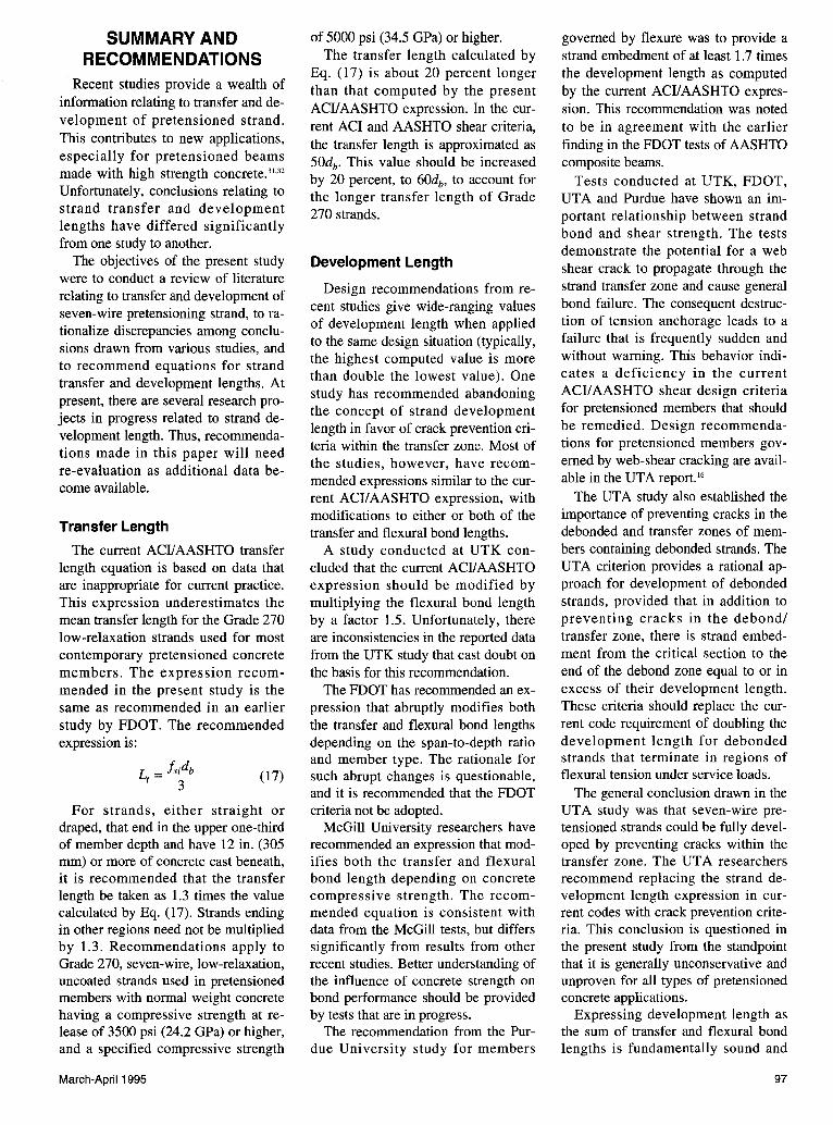
Fig. 9. Comparison of development length by various criteria.
current development length did one specimen reach full capacity without bond failure.
Recommended Development Length Equation
To ensure both strength and ductility in pretensioned concrete members, a more conservative development length expression is required for members that must attain large design strains. Test specimens proportioned to have strains at failure near yield (0.010) have usually achieved their predicted moment strengths at strand embedments calculated by the current ACI/AASHTO expression . Specimens proportioned to achieve strains at failure of about 0.035 have typically failed to reach their expected moment capacities due to premature bond failures .
To provide a conservative expression, it is recommended that the current expression for transfer length, fsedb/3, be replaced by the expression f sidb/3 . Further, the constant bond stress applied to the flexural bond length in the current expression should be replaced by a variable bond stress, similar to the approach followed by Hanson and Kaar. The variable bond stress should increase the development
96
length from its current value at cps = 0.010 to 1.7 times the current value at cps = 0.035, consistent with the recommendation from the study at Purdue University. This is accomplished by the expression:
where, for general applications, A is taken as (0.6 + 40cps) and cps is the strain corresponding to fps·
For many applications, design stress is approximated using Eq. (18-3) of the ACI Building Code. For these cases, strain is expressed in terms of OJP = Pp/'p.ff: and the equivalent expression for A is (0.72 + 0.102{31/wP) . Although the calculated strain in pretensioned concrete members fre quently exceeds 0.035, the ASTM specified minimum elongation is satisfied at 0.035, which corresponds to A = 2.0. It is reasonable then to set an upper limit of 2.0 for A. A lower bound of A = 1.0 applies for the unusual cases in which design strains are below yield, 0.01 . Thus:
Lo~ [ ;., =(0 . 6+40cps )]~2.0 (16)
Eq. (15) is plotted in Fig. 9 for an example rectangular beam with vary-
ing percentages of prestressed reinforcement. Also shown in the figure are the development lengths for this member calculated by several other criteria. Calculations for the example are included in Appendix A. Eq. (15) agrees with the current ACI!AASHTO expression for the case in which fps = 242 ksi (1.7GPa), where OJP = 0.36{3 1•
The equation yields about 1.6 times the current ACII AASHTO development length for f ps = 263 ksi ( 1. 8 GPa), where OJP = 0.072.
Strand development is often critical in pretensioned cantilevers , where strands typically have several feet of concrete cast beneath them. While none of the studies reviewed in this report have examined the effect of strand position on development length, there is evidence that settlement of freshly placed concrete and the accumulation of bleed water around strands can weaken bond. Studies at the University of Illinois found that the bond strength of strands with 10 in. (254 mm) or more of concrete cast beneath them was only about 75 percent of the strength for strands in similar specimens having only 2 in . (51 mm) of concrete below.29
Also, comparative end slips for top strands at transfer reported in the UTK study were, on average, .about 2.6 times the corresponding slips in the bottom strands of the same specimen.24
Tests have shown a correlation between large strand slip at transfer and poor strand development. 30
The ACI and AASHTO specifications both require that the basic development length of reinforcing bars be increased by a factor of 1.3 when horizontal reinforcing bars have 12 in. (305 mm) or more of concrete cast beneath. For these reasons, it is recommended that Eq. (18) be regarded as a basic development length and that it be multiplied by a factor of 1.3 when 12 in. (305 mm) or more of fresh concrete is placed below either a horizontal or draped strand that ends within the upper one-third region of a member's overall depth. For strands ending in other regions, the 1.3 multiplier need not be applied.
Several example problems to illustrate the proposed equation are included in Appendix B.
PCI JOURNAL
SUMMARY AND RECOMMENDATIONS
Recent studies provide a wealth of information relating to transfer and development of pretensioned strand. This contributes to new applications, especially for pretensioned beams made with high strength concrete.3
'·32
Unfortunately, conclusions relating to strand transfer and development lengths have differed significantly from one study to another.
The objectives of the present study were to conduct a review of literature relating to transfer and development of seven-wire pretensioning strand, to rationalize discrepancies among conclusions drawn from various studies, and to recommend equations for strand transfer and development lengths. At present, there are several research projects in progress related to strand development length. Thus, recommendations made in this paper will need re-evaluation as additional data become available.
Transfer Length
The current ACI/AASHTO transfer length equation is based on data that are inappropriate for current practice. This expression underestimates the mean transfer length for the Grade 270 low-relaxation strands used for most contemporary pretensioned concrete members. The expression recommended in the present study is the same as recommended in an earlier study by FDOT. The recommended expression is:
L _ fsidb (17) t- 3
For strands, either straight or draped, that end in the upper one-third of member depth and have 12 in. (305 mm) or more of concrete cast beneath, it is recommended that the transfer length be taken as 1.3 times the value calculated by Eq. (17). Strands ending in other regions need not be multiplied by 1.3. Recommendations apply to Grade 270, seven-wire, low-relaxation, uncoated strands used in pretensioned members with normal weight concrete having a compressive strength at release of 3500 psi (24.2 GPa) or higher, and a specified compressive strength
March-April 1995
of 5000 psi (34.5 GPa) or higher. The transfer length calculated by
Eq. (17) is about 20 percent longer than that computed by the present ACI/AASHTO expression. In the current ACI and AASHTO shear criteria, the transfer length is approximated as 50db. This value should be increased by 20 percent, to 60db, to account for the longer transfer length of Grade 270 strands.
Development Length
Design recommendations from recent studies give wide-ranging values of development length when applied to the same design situation (typically, the highest computed value is more than double the lowest value). One study has recommended abandoning the concept of strand development length in favor of crack prevention criteria within the transfer zone. Most of the studies, however, have recommended expressions similar to the current ACI/ AASHTO expression, with modifications to either or both of the transfer and flexural bond lengths.
A study conducted at UTK concluded that the current ACI/AASHTO expression should be modified by multiplying the flexural bond length by a factor 1.5. Unfortunately, there are inconsistencies in the reported data from the UTK study that cast doubt on the basis for this recommendation.
The FDOT has recommended an expression that abruptly modifies both the transfer and flexural bond lengths depending on the span-to-depth ratio and member type. The rationale for such abrupt changes is questionable, and it is recommended that the FDOT criteria not be adopted.
McGill University researchers have recommended an expression that modifies both the transfer and flexural bond length depending on concrete compressive strength. The recommended equation is consistent with data from the McGill tests, but differs significantly from results from other recent studies. Better understanding of the influence of concrete strength on bond performance should be provided by tests that are in progress.
The recommendation from the Purdue University study for members
governed by flexure was to provide a strand embedment of at least 1. 7 times the development length as computed by the current ACI/AASHTO expression. This recommendation was noted to be in agreement with the earlier finding in the FDOT tests of AASHTO composite beams.
Tests conducted at UTK, FDOT, UTA and Purdue have shown an important relationship between strand bond and shear strength. The tests demonstrate the potential for a web shear crack to propagate through the strand transfer zone and cause general bond failure. The consequent destruction of tension anchorage leads to a failure that is frequently sudden and without warning. This behavior indicates a deficiency in the current ACI/ AASHTO shear design criteria for pretensioned members that should be remedied. Design recommendations for pretensioned members governed by web-shear cracking are available in the UTA report. 16
The UTA study also established the importance of preventing cracks in the debonded and transfer zones of members containing debonded strands. The UTA criterion provides a rational approach for development of debonded strands, provided that in addition to preventing cracks in the debond/ transfer zone, there is strand embedment from the critical section to the end of the debond zone equal to or in excess of their development length. These criteria should replace the current code requirement of doubling the development length for debonded strands that terminate in regions of flexural tension under service loads.
The general conclusion drawn in the UTA study was that seven-wire pretensioned strands could be fully developed by preventing cracks within the transfer zone. The UTA researchers recommend replacing the strand development length expression in current codes with crack prevention criteria. This conclusion is questioned in the present study from the standpoint that it is generally unconservative and unproven for all types of pretensioned concrete applications.
Expressing development length as the sum of transfer and flexural bond lengths is fundamentally sound and
97
conceptually simple. Adopting the UTA crack prevention criteria would require a set of equations specific to the support conditions and loadings on the pretensioned concrete member. The current ACI/ AASHTO approach is consistent with the code treatment of "attainable average bond stress over the length of embedment" (see Ref. 1, p. R-181) that has been successfully applied to nonprestressed reinforcement for many years. There is merit to retaining a concept that has been a part of the ACI Code for 30 years. Modifications to both the transfer and flexural bond lengths are needed, but the basic concept should be preserved.
The current ACI! AASHTO development length expression is generally unconservative. Fortunately, strand development rarely governs the design of pretensioned concrete members. The relatively few documented bond related failures in pretensioned members is probably due to the infrequent occurrence of critical conditions, instead of adequate safety in the design criteria.
Pretensioned concrete beams failing in general bond and followed by ultimate flexural failure typically show gradual, ductile failures. However, many bond related failures in test specimens have shown a relationship with shear strength, and generally fail in a sudden mode without adequate warning. The possibility of such failures demands conservative development length criteria, consistent with the strength design philosophy of current codes. A conservative expression for strand development recommended in this study is the following:
(18)
where for general applications, the multiplier A is taken as (0.6 + 40ep,).
For applications in which design stress is calculated by the approximate Eq. (18-3) of the ACI Code, an equivalent expression (0.72 + 0.102{31/wp) is required to compute A. In either case, A shall be taken greater than or equal to 1.0 and less than or equal to 2.0. For strands, either straight or draped, ending in the upper one-third of member depth and having 12 in. (305 mm) or more of concrete cast beneath, it is recommended that the length calculated by
98
Eq. (18) be increased by a factor 1.3. For strands ending in other regions, the 1.3 multiplier need not be applied.
ACKNOWLEDGMENTS This paper stems from a study the
author conducted as a visiting research engineer at the Turner-Fairbanks Highway Research Center (TFHRC) of the Federal Highway Administration (FHW A) while on leave from the Virginia Military Institute (VMI). Financial support provided by the Wachtmeister Sabbatical Leave Program at VMI and by FHW A is gratefully acknowledged. Opinions expressed in the paper are those of the author and do not necessarily reflect those of FHW A.
The cooperation and help provided by the Precast/Prestressed Concrete Institute (PCI) is gratefully appreciated. Paul Johal, PCI's Research Director, visited TFHRC three times during the course of the project and contributed significantly by providing documents, reviewing report drafts and offering insight into related research.
The author appreciates the time and effort from many individuals who reviewed report drafts and offered suggestions for improvement. In many cases, the reviewer's opinions differ significantly from those of the author and are not necessarily reflected in the final report. Comments and suggestions were provided by the following: Susan Lane, Lloyd Cayes and Jim Hoblitzell of FHW A; John Dick, Paul Johal and George Nasser of PCI; Basile Rabbat of PCA; Edwin Burdette of UTK; Ned Burns of UTA; Julio Ramirez of Purdue University; Bruce Russell of the University of Oklahoma; and Mohsen Shahawy of FDOT Structures Research Center.
REFERENCES I. ACI Committee 318, "Building Code
Requirements for Reinforced Concrete (ACI 318-89)," American Concrete Institute, Detroit, MI, 1989.
2. AASHTO, Standard Specifications for Highway Bridges, Fifteenth Edition, American Association of State Highway and Transportation Officials, Washington, D.C., 1992.
3. Hanson, N. W., and Kaar, P. H., "Flexural Bond Tests of Pretensioned Prestressed Beams," ACI Journal, V. 55, No.7, 1959, pp. 783-803.
4. Tabatabai, H., and Dickson, T. J., "The History of the Pretensioning Strand Development Length Equation," PCI JOURNAL, V. 38, No. 6, November-December 1993, pp. 64-75.
5. Martin, L. D., and Scott, N. L., "Development of Prestressing Strand in Pretensioned Members," ACI Journal, V. 73, No. 8, August 1976, pp. 453-456.
6. Anderson, Arthur R., Anderson, Richard G., Holmberg, Ake, Martin, Leslie D., Scott, Norman L., Nijhawan, Jagdish C., Sanderson, K. J., Zia, P., and Mostafa, T., Discussion of Ref. 7, "Development Length of Prestressing Strands," PCI JOURNAL, V. 23, No. 4, July-August 1978, pp. 97-106.
7. Zia, P., and Mostafa, T., "Development Length of Prestressing Strands," PCI JOURNAL, V. 22, No. 5, September-October 1977, pp. 54-65.
8. Cousins, T. T., Johnston, D. W., and Zia, P., "Transfer and Development Length of Epoxy-Coated and Uncoated Prestressing Strand," PCI JOURNAL, V. 35, No. 4, July-August 1990, pp. 92-103.
9. FHWA, "Prestressing Strand for Pretension Applications - Development Length Revisited," Memorandum, Chief, Bridge Division, Federal Highway Administration, Washington, D.C., October 1988.
10. Russell, Bruce W., "Impact of High Strength Concrete on the Design and Construction of Pretensioned Concrete Bridges," PCI JOURNAL, V. 39, No.4, July-August 1994, pp. 76-89.
11. Deatherage, J. H., Burdette, E. G., and Chew, C. K., "Development Length and Lateral Spacing Requirements of Prestressing Strand for Prestressed Concrete Bridge Girders," PCI JOURNAL, V. 39, No. 1, January-February 1994, pp. 70-83.
12. Shahawy, M. A., Issa, M., and Batchelor, B., "Strand Transfer Lengths in Full Scale AASHTO Prestressed Concrete Girders," PCI JOURNAL, V. 37, No.3, May-June 1992, pp. 84-96.
13. Shahawy, M., and Batchelor, B., "Bond and Shear Behavior of Prestressed AASHTO Type II Beams," Progress Report No. 1, Structural Research Center, Florida Department of Transportation, February 1991.
14. Shahawy, M.A., and Issa, M., "Effect of Pile Embedment on the Develop-
PCI JOURNAL
ment Length of Prestressing Strands," PCI JOURNAL, V. 37, No.6, November-December 1992, pp. 44-59.
15. Lane, S. N., "Development Length of Prestressing Strand," Public RoadsA Journal of Highway Research and Development, Federal Highway Administration, V. 54, No. 2, September 1990,pp.200-205.
16. Russell, B. W., and Burns, N. A., "Design Guidelines for Transfer, Development and Bonding of Large Diameter Seven-Wire Strands in Pretensioned Concrete Girders," Research Report No. 1210-SF, Center for Transportation Research, University of Texas at Austin, Austin, TX, 1993, 286 pp.
17. Abdalla, 0. A., Ramirez, J. A., and Lee, R. H., "Strand Debonding in Pretensioned Beams - Precast Prestressed Concrete Bridges With Debonded Strands - Simply Supported Tests," Part 2, Final Report FHW AI INDOT/JHRP-92, 1993,228 pp.
18. Cousins, T. E., Francis, L. H., Stallings, J. M, and Gopu, V. K. A., "Spacing and Cover Requirements of Epoxy-Coated Prestressing Strands in Unconfined Sections," PCI JOURNAL, V. 38, No. 5, September-October 1993, pp. 76-84.
19. Mitchell, D., Cook, W. D., Khan, A. A., and Tham, T., "Influence of High Strength Concrete on Transfer and Development Length of Pretensioning Strand," PCI JOURNAL, V. 38, No.3, May-June 1993, pp. 52-66.
20. den Uijl, J. A., "Background CEB-FIP MC90 Clauses on Anchorage and Transverse Tensile Actions in the An-
March-April 1995
chorage Zone of Prestressed Concrete Members," Draft Bulletin of the CEB, Delft University of Technology, Delft, The Netherlands.
21. Balazs, G. L., "Transfer Lengths of Prestressing Strand as a Function of Draw-in and Initial Prestress," PCI JOURNAL, V. 38, No. 2, MarchApril1993, pp. 86-93.
22. Loov, R., "A General Equation for the Steel Stress for Bonded Prestressed Concrete Members," PCI JOURNAL, V. 33, No. 6, November-December 1988, pp. 108-148.
23. Buckner, C. D., "An Analysis of Transfer and Development Lengths for Pretensioned Concrete Structures," Report No. FHWA-RD-94-049, Federal Highway Administration, Washington, D.C., December 1994, 108 pp.
24. Deatherage, J. J., and Burdette, E. G., "Development Length and Lateral Spacing Requirements of Prestressing Strand for Prestressed Concrete Bridge Products," PCI Report, Transportation Center, University of Tennessee, Knoxville, September 1991, 127 pp.
25. Deatherage, J. H., Chew, C. K., and Burdette, E. G., "Behavior of Prestressed AASHTO Girders Under Static Loading," Preprint No. 0870, Transportation Research Board, National Academy of Sciences, Washington, D.C., January 1993, 23 pp.
26. Shahawy, M., "An Investigation of Shear Strength of Pretensioned Concrete AASHTO Type II Girders," Structures Research Center, Florida Department of Transportation, May 1993, 132 pp.
27. Buckner, C. D., Shahawy, M. A., and Issa, M., Discussion of "Effect of Pile Embedment on the Development Length of Prestressing Strands," PCI JOURNAL, V. 38, No. 5, SeptemberOctober 1993, pp. 86-88.
28. Russell, B. W., and Burns, N. H., "Development Length and Flexural Bond Behavior of AASHTO-Type Girders With Fully Bonded and Blanketed Strands," Technical Memo 1210-2, Center for Transportation Research, University of Texas at Austin, Austin, TX, March 1991, 20 pp.
29. Stocker, M. F., and Sozen, M.A., "Investigation of Prestressed Concrete for Highway Bridges, Part VI: Bond Characteristics of Prestressing Strand," Bulletin 503, University of Illinois, Urbana, Illinois, 1970.
30. Anderson, A. R., and Anderson, R. G., "An Assurance Criterion for Flexural Bond in Pretensioned Hollow Core Units," AC/ Journal, V. 73, No. 8, August 1976, pp. 457-464.
31. Russell, B. W., and Burns, N. H., "Static and Fatigue Behavior of Pretensioned Composite Bridge Girders Made With High Strength Concrete," PCI JOURNAL, V. 38, No. 3, MayJune 1993,pp.116-128.
32. Ralls, M. A., Ebonies, L., and Panache, J. J., "The New Texas UBeam Bridges: An Aesthetic and Economical Design Solution," PCI JOURNAL, V. 38, No. 5, SeptemberOctober 1993, pp. 20-29.
33. PC/ Design Handbook: Precast and Prestressed Concrete, Fourth Edition, Precast/Prestressed Concrete Institute, Chicago, IL, 1992.
99
APPENDIX A- STRAND DEVELOPMENT LENGTH BY DIFFERENT CRITERIA
A problem example is useful in comparing development lengths calculated by various criteria. Consider a rectangular pretensioned concrete beam 12 in. (305 mm) in width, 32 in. (813 mm) in overall depth, and 28 in. (711 mm) in effective depth. Data for the example are: effective prestress of 160 ksi (1.1 GPa); strand stress immediately after transfer of 180 ksi (1.2 GPa); concrete strength at release of 4000 psi (27.6 MPa); and specified compressive strength of 5000 psi (34.5 GPa).
The minimum number of 1/z in. (12.7 mm) diameter strands that furnish a moment strength in excess of 1.2Mcr is three. The maximum number of 1iz in. (12.7 mm) diameter strands that provide ductile failure is 12. The corresponding strand stress at failure ranges from 242 ksi (1.7 GPa) with 12 strands to 263 ksi (1.8 GPa) for three strands, as approximated by Eq. (18-3) of the ACI Code. Sample calculations below are for the case using three strands. Results for other cases are shown in Fig. 9.
In the sections to follow, the embedment length required to develop the strand stress of 263 ksi (1.8 GPa) is calculated by current and proposed development length criteria.
Hanson and Kaar Criteria
The Hanson and Kaar criteria were developed from tests on Grade 250 strand. For comparison purposes, their local bond stresses will be assumed applicable to the Grade 270 strands of the example.
Transfer length is based on a bond stress of 400 psi (2.8 MPa), which applies to the actual strand perimeter [i.e., 2.09 in. (53.3 mm) for a 1iz in. (12.7 mm) diameter strand]. Thus, to transfer an effective prestress of 160 ksi (1.1 GPa) in the strands requires:
= 160 X 0.1531(0.4 X 2.09) = 29 in. (737 mm)
(Al)
Hanson and Kaar provide local bond stresses in a curve in Fig. A-1 of their paper. This figure is reproduced as Fig. 5 of this paper. Using linear interpolation, the average bond stress over the first 25 in. (635 mm) from the end of the transfer zone is approximated for 5 in. (127 mm) increments. This results in successive values of 225, 125, 80, 65, and 55 psi (1550, 863, 552, 449, and 380 kPa). The average bond stress beyond 25 in. (635 mm) is approximated as 50 psi (345 kPa). On this basis, the development length is:
Ld = 4 + [(ips- fse )Aps -Suo;!( ub,ave ); ] I (0. 05uo )+ 25
(A2)
= 29 + [(263- 160)0.153- (5)(2.09)(0.250 + 0.080 + 0.065 + 0.055)]1(0.050 X 2.09) + 25
= 146 in. (3.7 m)
100
AASHTO Specification Prior to 1973
In 1973, AASHTO adopted the development length equation that was included in the 1963 ACI Code. Before adoption, AASHTO simply used the minimum embedment required to develop the breaking strength of Grade 250 strand, which was calculated as 134 in. (3.4 m) for 1iz in. (12.7 mm) diameter strand by Hanson and Kaar.
Current ACI/AASHTO Method
The development length equation proposed by ACI Committee 323 is currently included in both the ACI 318 and AASHTO Specifications. From this equation:
Ld =(ips-~ ise )db
= [263 -0.67(160) ]0.5
= 78 in. (2.0 m)
Martin and Scott Equation
(A3)
The equations proposed by Martin and Scott are curves of best fit to the Hanson and Kaar data. Using the equation for 1iz in. (12.7 mm) diameter strand gives:
Ld = (di0.39)[fps- 1351db116] (A4)
= (0.510.39)[263 - 13510.5<116)]
= 143 in. (3.63 m)
Zia and Mostafa Equation
The development length equation proposed by Zia and Mostafa is more conservative than the current ACII AASHTO equation. This equation gives:
= (1.5 X 180 I 4.0)0.5- 4.6+ 1.25(263 -160)0.5
= 94 in. (2.4 m)
Proposed UTK Equation
(A5)
The expression proposed in the UTK final report gives:
Ld = ~e db + 1. 42( ips -he )db
= (160 I 3)0.5 + 1.42(263-160)0.5
= 100 in. (2.54 m)
FOOT Proposal
(A6)
The FDOT proposal provides significantly different results for piles, slabs and girder sections. For the beam of the example problem, the data are assumed such that kb = 2; thus:
PCI JOURNAL
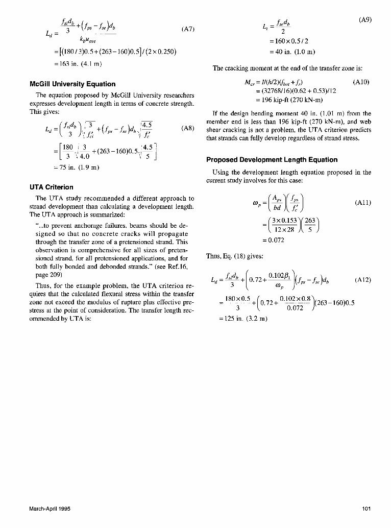
= [(180 I 3)0.5 + (263 -160)0.5]/ (2 X 0.250)
=163in. (4.lm)
McGill University Equation
(A7)
The equation proposed by McGill University researchers expresses development length in terms of concrete strength. This gives:
L _ ( fsidb ) / 3 + (f _ f, )d /4.5 (AS) d - 3 IJ fci ps se b V J;
=[180 I 3
+(263-16o)o.5 /4
·5
] 3 lj 4.0 \ 5
= 75 in. (1.9 m)
UTA Criterion
The UTA study recommended a different approach to strand development than calculating a development length. The UTA approach is summarized:
" ... to prevent anchorage failures, beams should be designed so that no concrete cracks will propagate through the transfer zone of a pretensioned strand. This observation is comprehensive for all sizes of pretensioned strand, for all pretensioned applications, and for both fully bonded and debonded strands." (see Ref.l6, page 209)
Thus, for the example problem, the UTA criterion requires that the calculated flexural stress within the transfer zone not exceed the modulus of rupture plus effective prestress at the point of consideration. The transfer length recommended by UTA is:
March-April1995
L = fsedb t 2
(A9)
=160x0.5/2
= 40 in. (1.0 m)
The cracking moment at the end of the transfer zone is:
Mer= l/(h/2)lfbot + !,.) = (32768/16)(0.62 + 0.53)/12 = 196 kip-ft (270 kN-m)
(AlO)
If the design bending moment 40 in. (1.01 m) from the member end is less than 196 kip-ft (270 kN-m), and web shear cracking is not a problem, the UTA criterion predicts that strands can fully develop regardless of strand stress.
Proposed Development Length Equation
Using the development length equation proposed in the current study involves for this case:
coP=(~~)(;; J (All)
= (3x0.153)(263) 12x28 5
=0.072
Thus, Eq. (18) gives:
Ld = fsidb +[0.72+ 0.102/31 )Vps- fse)db (A12) 3 coP
= 180x0.5 +(0. 72 + 0.102x0.8)(263 _ 160)0.5 3 0.072
= 125 in. (3.2 m)
101
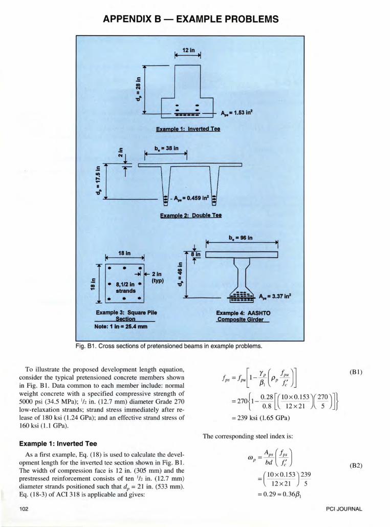
APPENDIX 8 - EXAMPLE PROBLEMS
181n
.5 ~ A
TJ ..
~ 121n ~
ExamPle 1: Inverted Tee
r b.= 381n 1
\:1 -A,. • 0.459 ln2 ~ 1:1 u
Example 2: Double Itt
-tl ~ 21n I . . .
~ ~...··-a_,1_/2_1_n_·_. (typ) strands
• • Example 3: Squara Pile
Section Example 4: AASHTO ComPOsite Girder
Note: 1 In·• 25.4 rom
Fig. 8 1. Cross sections of pretensioned beams in example problems.
fps =Jp{1- ;~ (Pp ;; Jl (B1) To illustrate the proposed development length equation, consider the typical pretensioned concrete members shown in Fig. B 1. Data common to each member include: normal weight concrete with a specified compressive strength of 5000 psi (34.5 MPa); 1/z in. (12.7 mm) diameter Grade 270 low-relaxation strands; strand stress immediately after release of 180 ksi (1.24 GPa); and an effective strand stress of 160 ksi (1.1 GPa).
= 270{1- 0. 28 [( 10 X 0.153 )( 270 )]} 0.8 12x21 5
Example 1: Inverted Tee
As a first example, Eq. (18) is used to calculate the development length for the inverted tee section shown in Fig. B 1. The width of compression face is 12 in. (305 mm) and the prestressed reinforcement consists of ten 1/z in. (12.7 mm) diameter strands positioned such that dP = 21 in. (533 mm). Eq. (18-3) of ACI 318 is applicable and gives:
102
= 239 ksi (1.65 GPa)
The corresponding steel index is:
wP = :; ( ; ; J (B2)
= (10 x 0.153) 239 12 X 21 5
= 0.29"" 0.36/3,
PCI JOURNAL
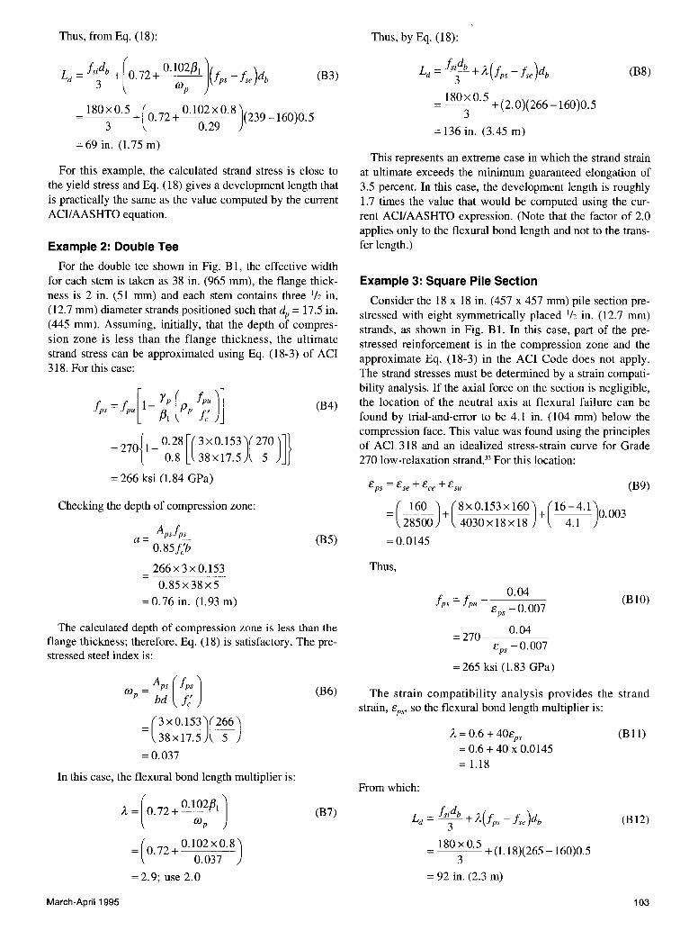
Thus, from Eq. (18):
Ld = fsidb + (o. 72 + 0.1()2/31 ]Vps - fse )db (B3) 3 (J)p
= 180
x 0
·5
+ (o. 72 + Q.l0~><9~~)(239 -I60)o.s 3 0.29
= 69 in. (I. 75 m)
For this example, the calculated strand stress is close to the yield stress and Eq. (18) gives a development length that is practically the same as the value computed by the current ACIJ AASHTO equation.
Example 2: Double Tee
For the double tee shown in Fig. B1, the effective width for each stem is taken as 38 in. (965 mm), the flange thickness is 2 in. (51 mm) and each stem contains three 1h in. ( 12.7 mm) diameter strands positioned such that dP = 17.5 in. (445 mm). Assuming, initially, that the depth of compression zone is less than the flange thickness, the ultimate strand stress can be approximated using Eq. (18-3) of ACI 318. For this case:
= 270{1- 0.28 [( 3 x0.153)(~?9)]} 0.8 38x17.5 5
= 266 ksi (1.84 GPa)
Checking the depth of compression zone:
Apsfps a=~---'--
0.85J;b
266x3x0.153 0.85x38x5
= 0. 76 in. (1. 93 m)
(B4)
(B5)
The calculated depth of compression zone is less than the flange thickness; therefore, Eq. (18) is satisfactory. The prestressed steel index is:
OJ = Aps (fps) p bd t:
= (3x0.1~~)(?66) 38x17.5 5
=0.037
In this case, the flexural bond length multiplier is:
March-April 1995
A=( 0.72+Q}~~pj_)
=(0.?2+ 0.102x0.8) 0.037
= 2.9; use 2.0
(B6)
(B7)
Thus, by Eq. (18):
Ld = ~~~!z_ +A {!ps - fse )db
= 180xO.S +(2.0)(266-160)0.5 3
= 136 in. (3.45 m)
(B8)
This represents an extreme case in which the strand strain at ultimate exceeds the minimum guaranteed elongation of 3.5 percent. In this case, the development length is roughly 1.7 times the value that would be computed using the current ACIJAASHTO expression. (Note that the factor of 2.0 applies only to the flexural bond length and not to the transfer length.)
Example 3: Square Pile Section
Consider the 18 x 18 in. (457 x 457 mm) pile section prestressed with eight symmetrically placed 1/z in. (12.7 mm) strands, as shown in Fig. B I. In this case, part of the prestressed reinforcement is in the compression zone and the approximate Eq. (18-3) in the ACI Code does not apply. The strand stresses must be determined by a strain compatibility analysis. If the axial force on the section is negligible, the location of the neutral axis at flexural failure can be found by trial-and-error to be 4.1 in. (104 mm) below the compression face. This value was found using the principles of ACI 318 and an idealized stress-strain curve for Grade 270 low-relaxation strand.33 For this location:
(B9)
= (--1_()2__) + ( 8 X 0.153 X 160) + ( 16- 4.1)0.003 28500 4030xl8x18 4.1
= 0.0145
Thus,
0.04 ips= fpu- cps -0.007
= 270- ___ O_.Q±__ cps -0.007
= 265 ksi (1.83 GPa)
(BIO)
The strain compatibility analysis provides the strand strain, cps• so the flexural bond length multiplier is:
From which:
A= 0.6 + 40cps = 0.6 + 40 X 0.0145 = 1.18
Ld = fs~d!J_ + A(!ps - fse )db
= 180xO.S +(1.18)(265-160)0.5 3
= 92 in. (2.3 m)
(Bll)
(B12)
103
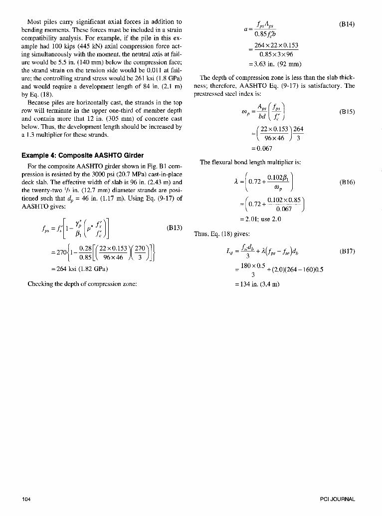
Most piles carry significant axial forces in addition to bending moments. These forces must be included in a strain compatibility analysis. For example, if the pile in this example had 100 kips (445 kN) axial compression force acting simultaneously with the moment, the neutral axis at failure would be 5.5 in. (140 mm) below the compression face; the strand strain on the tension side would be 0.011 at failure; the controlling strand stress would be 261 ksi (1.8 GPa) and would require a development length of 84 in. (2.1 m) by Eq. (18).
Because piles are horizontally cast, the strands in the top row will terminate in the upper one-third of member depth and contain more that 12 in. (305 mm) of concrete cast below. Thus, the development length should be increased by a 1.3 multiplier for these strands.
Example 4: Composite AASHTO Girder
For the composite AASHTO girder shown in Fig. B 1 compression is resisted by the 3000 psi (20.7 MPa) cast-in-place deck slab. The effective width of slab is 96 in. (2.43 m) and the twenty-two 1/z in. (12.7 mm) diameter strands are positioned such that dP = 46 in. (1.17 m). Using Eq. (9-17) of AASHTO gives:
!,, = t:[ 1- ;, k jj) l (B13)
= 270{1- 0.28 [( 22 X 0.153)(270)]} 0.85 96x46 3
= 264 ksi (1.82 GPa)
Checking the depth of compression zone:
104
fpsAps a = __._____.___ 0.85J:b
264x22x0.153
0.85x3x96
= 3.63 in. (92 mm)
(B14)
The depth of compression zone is less than the slab thickness; therefore, AASHTO Eq. (9-17) is satisfactory. The prestressed steel index is:
wP = ~; (;;)
=(22x0.153)264 96x46 3
=0.067
The flexural bond length multiplier is:
A= [ 0. 72 + 0.1~~/J, l =(0.72 + 0.102x0.85)
0.067
=2.01; use 2.0
Thus, Eq. (18) gives:
Ld = fs~db + A-(!ps - fse )db
= 180
X 0·5 + (2.0)(264 -160)0.5
3 = 134 in. (3.4 m)
(Bl5)
(B16)
(Bl7)
PCI JOURNAL
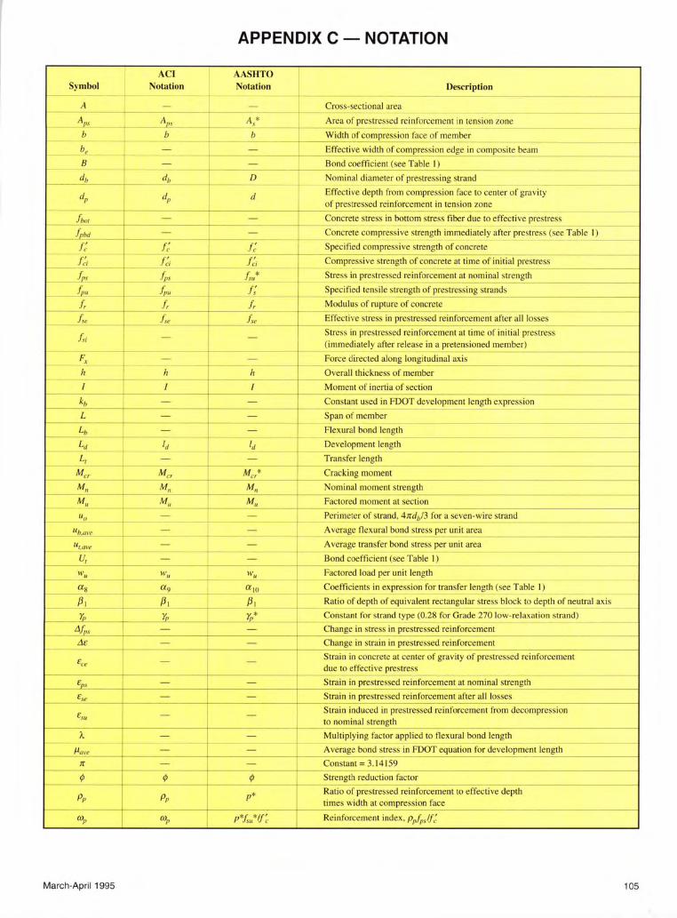
APPENDIX C - NOTATION
ACI AASHTO Symbol Notation Notation Description
--
t~ A - - Cross-sectional area
--~ ---Af'S Af>I A * Area of prestressed re inforcement in tension zone
~
s '-~
b b b Width of compression face of member (
b, - - Effective width of compression edge in composite beam ~
B - - Bond coefficient (see Table I) "' db
m db D Nominal diameter of prestressing strand I' -- ' ·-
dl' dl' d Effective depth from compression face to center of gravity of prestressed reinforcement in tension zone foo,£ - -- Concrete stress in bottom stress fiber due to effective prestress
--
);<"
f,M ;c_ ~ l-~=-Concrete compressive strength immediately after prestress (see Table I)
f~ f~ f~ Specified compressive strength of concrete
-f ci fci f ci _i Compressive strength of concrete at time of initial prestress
fps _l J;rs , _f.. . .,* Stress in prestressed reinforcement at nominal strength
~)/I J,m J; Specified tensi le strength of prestressing strands ..
... };. !, =r !, Modulus of rupture of concrete
f,_ f oe f ,_ ...
Effective stress in prestressed reinforcement after all losses -
1
f ,i - - " Stress in prestressed reinforcement at time of initial prestress
!
t· (immediately after release in a pretensioned member)
~
F, - - Force directed along longitudinal axis -~- -h h c h Overall thickness of member
-- ---I I I Moment of inertia of section --
kb - - Constant used in FOOT development length expression - ~ --
L - +- - Span of member
Lb - - Flexural bond length -
Ld ld ld Development length
L, - - Transfer length ·-c
* "' Mer M er M er Cracking moment -~ -
M, M, M, Nominal moment strength ~ ~ --
M., M, M, Factored moment at section - ~
llu I - - Perimeter of strand, 4rrdb/3 for a seven-wire strand
flb.m·e - - _ Average flexural bond stress per unit area
u,_m·e - - Average transfer bond stress per unit area __, - I .. u, - - Bond coefficient (see Table I) -
WI/ lt'/1 wu Factored load per unit length -
f-as a9 aJO Coefficients in expression for transfer length (see Table I)
/31 /31 /31 Ratio of depth of equivalent rectangular stress block to depth of neutral axis
)j, r;, )j,* Constant for strand type (0.28 for Grade 270 low-relaxation strand) -
-+ tlJ;,s - - Change in stress in prestressed reinforcement
de ~
Change in strain in prestressed reinforcement - -~-
Ece -I
- Strain in concrete at center of gravity of prestressed reinforcement due to effective prestress
---C~
f ps - - Strain in prestressed reinforcement at nominal strength - -
€se - - Strain in prestressed reinforcement after all losses
E_w - - Strain induced in prestressed reinforcement from decompression to nominal strength ... ,,__, __
'A - - Multiplying factor applied to flexural bond length -- ' ~ -
J.lm•e - - Average bond stress in FOOT equation for development length
7r - - Constant= 3.14 I 59 ·- - ---
¢ ¢ ¢ Strength reduction factor ~r- _,
Pp Pp p * Ratio of prestressed reinforcement to effective depth times width at compression face
~
WI' WI' p*fw*lf~ Reinforcement index, p1J;,.JJ:
March-April 1995 105