Embed Size (px)
Citation preview


THE UNIVERSITY
OF ILLINOIS
LIBRARY


A STUDY OF CONCRETE MIXERS
BY
JOHN WILHELM SIMMONS Jr.
THESIS
FOR THE
DEGREE OF BACHELOR OF SCIENCE
IN
CIVIL ENGINEERING
COLLEGE OF ENGINEERING
UNIVERSITY OF ILLINOIS
1912


UNIVERSITY OF ILLINOIS
COLLEGE OF ENGINEERING;
May z%% 1912
This is to certify that the thesis of JOHN WILHELM SIMMONS,
Jr., entitled a STUDY OF CONCRETE MIXERS was prepared under my per-
sonal supervision; and I recommend that it be approved as meeting
this part of the requirements for the degree of Bachelor of science
in Civil Engineering.
Instructor in civil Engineering.
Recommendation approved:
Professor of Civil Engineering.

UKJC

TABLE OF CONTENTS
PageIntroduction 1
Present Types of Mixers 2
Batch Mixers 3
Double Conical Drum 3
Smith Mixer 5
Cylindrical Drum 10
Eclipse Mixer 11
Chicago Mixer 14
Milwaukee Mixer 18
Cubical Drum 22
Austin Cube Mixer 22
Continuous Mixers 25
Eureka Mixers 26
Comparison of Batch and Continuous Types of Mixers. 31
Hand Mixers of the Batch Types 33
Gravity Mixers 35
Conclusion 36

Digitized by the Internet Archive
in 2013
http://archive.org/details/studyofconcretemOOsimm

A STUDY OF COITCRETE MIXERS.
Concrete is not of modem origin ,as is commonly supposed,
but is known to have "been used in very ancient times. The early
records of civilization show that the cementing power of certain
soils and rocks was known and utilized. The ancient Egyptians
used certain clays which they strengthened by mixing in straw. The
old Romans knew the cementing qualities of certain volcanic dust
and rocks and used them in many of their works of construction.
However, the remarkable development of the use of
concrete belongs to this age. It began in Europe and was brought to
a practical stage there before its introduction into this country.
In about 1850, Monier, a French gardener, introduced what is now
known as reinforced concrete. He discovered that by embedding
wires or iron rods in concrete, it was made stronger. This gave an
added impetus to the use of concrete but it was not until about 1800
that it was accepted as a safe form of construction for extensive
economical application.
One of the most important problems in the development
of concrete construction has been, how to mix the ingredients in
the best and most economical manner. Probably the first attempts
to mix concrete by machinery were made about 1890, all mixing
previous to that having been done by hand labor.
To mix concrete by hand the material is first thrown
upon a large mixing board and then mixed by repeated shoveling;
usually requiring to be completely shoveled over four times dry


-2-
and four more times after the water is added. This process is very
slow and tiresome to the laborers and is now only used where small
amounts of concrete are needed and the size of the job would not
warrant the expense of installing a machine mixer. The increase
in the amount of concrete to he used on one job, and the cost,
slowness and unreliability of mixing large amounts by hand, combined
to make the invention of a practical machine mixer, a necessity.
The rapid development of machine mixing within the last
decade proves that it is a practical and economical method of making
concrete. There are a great many concrete mixers on the market,
each of which has advantages, and all of which are more practical
and as efficient as hand mixing. All of these different mixers
cannot be taken up and their relative merits discussed in this
article, but the writer has chosen to describe what he considers
as representative mixers.
PRESENT TYPES OF MIXERS.
The machine mixers used at present may be classified
as power mixers with revolving drums and power mixers with
revolving blades or paddles. The first class is known as the batch
mixer, that is, the continuity of the operation is broken when
the mixer is emptied. The second class is known as the continuous
mixer. In this the process of mixing is not interrupted when the
mixer is being filled with material or when it is being emptied.


-3-
BATOH I.IIXERS.
DOUBLE GOITIGAL DRUM.
Perhaps the most common type of "batch mixer is the
double conical, revolving drum. The drum has the shape of two
frust rums of cones with their "bases together. It is mounted on
trunnions so that it can be partially revolved in the vertical
plane of its long axis. In the process of mixing, the drum is
revolved in a vertical plane perpendicular to its long axis. During
the revolution the contained material is lifted and dropped "by vanes
fastened to the inner surface of the drum. This lifting and dropping
of the material mixes it. The revolution of the drum is effected
in several ways, the most common of which is to place the drum on
two or more rollers. The power is usually transmitted to the drum
by a beveled gear meshing with a gear band encircling the drum at
its center. The trunnions, it should have been said, support a
cradle in which the rollers holding the drum, are placed. This
permits the tilting of the machine, when emptying, without stopping
the revolutions of the drum.
The principle of the mixing depends upon the revolving of
the drum, and the falling of the contained batch against vanes, set
obliquely on the interior surface of the drum. The slope of the
drum causes the material to gravitate to the bottom. The revolving
of the drum allows the vanes to catch it and lift it up, after
which gravity again acts and it slides off the vanes successively
from one to the other. Two or three revolutions of the drum are
considered sufficient to mix the batch.


-4-
The method of operation is as follows: The drum being
in a horizontal position when ready to he charged, the material is
emptied into a hopper which conducts it into the drum in a dry
state,, and it is allowed to be partially mixed before the water is
added, v/hen the batch is thoroughly mixed, the drum is tilted
forward and the mix allowed to run out into the forms or concrete
conveyor. The amount of concrete which can be mixed at one time is
limited by the size of the mixer.
In general, the feed end of conical drum mixers is
elevated some distance from the ground. This necessitates the
elevating of all the material which goes through the machine. In
some cases this difficulty is removed by lowering the mixer so that
the feed end is at the same level as that at which the material
is delivered. Another method is that of having an automatic feed
hopper. In the charging position this hopper is placed low enoughmore
so that the material does not have to be raised/than for ordinary
handling. After the hopper has been charged it is raised by
mechanical means and the charge delivered to the mixer.
Two methods are used in proportioning and feeding the
mixer. The more common of the two is to proportion the material by
hand and deliver it to the mixer in wheel barrows. A certain number
of barrows of sand and of gravel and bags of cor.cnt being required
for each batch. The other method .which is sometimes used on
large jobs, is to proportion and feed the material to the mixer
mechanically. All the material is delivered at an elevation above
the mixer and is placed in bins over the feed end of the machine.


-5-
These bins, at their discharge points, have compartments which will
hold just enough of the material for one hatch and which are
operated mechanically, discharging directly into the mixer.one of
Water is added to the "batch in the mixer in/two ways.
Ordinarily the required amount is measured in "buckets and thrown
into the mixer by hand. Automatic water tanks are now made which
can he so set to discharge the required amount of water for each
hatch into the machine. The tanks are placed at an elevation a
little above the mixer, i'hey may be supplied with water by hand
or a pipe line run up to them.
THE SMITH MIXER.
One of the most common types of the conical drum mixers
in present use is that made by the T. L. Smith Company of Chicago.
(See Fig. l)
Figure 1.


-6-
The drum rests in a U shaped cradle. To the upper parts
of the U frame are attached tv/o steel arms or trunnions which
in turn project through the supporting frames of the machine or
pedestals as they might he called. (See Pig. 2) Ihe cradle swings
Figure 2.
freely in the trunnions. The U frame is of channel steel and is
rigidly braced with angle iron uprights and stiffeners. The drum
is supported by main rollers placed at the bottom of the cradle and
its alignment is preserved by six guide rollers. A central ring
around the drum serves as a track for the rollers and also carries
the gear teeth of the driving mechanism.
Then the drum is to be discharged, the cradle is swung
upon its trunnions and the drum tilted to a steep angle. The driving
shaft passes through one of' the trunnions, which is hollow and is


-7-
the center of the tilting circle, which permits the drum to be
discharged while still revolving. (See Fig. oS
Figure 3.
She drum is made up of two cones riveted to a central
ring and is provided with removable linings to reinforce the shell
at the points where the falling material may produce the greatest
wear. The driving mechanism is located at the central part of the
drum and is farthest away from the feeding and discharge ends in
order to be in a measure protected from material spilled in feeding
or discharging.
The vanes or blades are riveted in V shaped sets on the
inner surface of the drum at an angle to its central axis. (See Fig. 4)
Y/hen the drum is revolved these blades carry up the material which
always gravitates back to the center of the drum, The converging


-8-
Figure 4.
masses of concrete are forced through narrow openings "between the
blades and are thus broken up and intermingled into a uniform mass.
The batch, during the process of mixing, traverses an irregular
path by a somewhat serpentine motion due to the interference of the
blades.
The feed end of the drum is shortened as compared to the
discharge end and is given a steeper slope. This causes the material
entering the mixer to gravitate more quickly to the center of the
drum, thus increasing the rapidity with which, the mixer may be fed.
A steel feed spout forms a part of the mixer and is supported by
two rods and an A shaped bracket fastened to the cradle. (See Pig. 5)
Figure 5.


_0_
Adjusting screws are placed in the "bracket so that the spout can "be
raised or lowered so as to clear the edge of the drum.
The power to turn the drum is transmitted, "by a miter
gear upon the main shaft, to a spur gear upon the cross shaft.
The spur gear of the cross shaft meshes with the gear band
encircling the drum. It is claimed "by the manufacturers that this
is a better drive than the direct driven method for the reason that
in the second method the driving "bevel is always crowding the driven
gear which has only the weight of the drum to hold it in position.
Also a mesh of "bevel gears is always injuriously affected by the
settling of the drum due to wear. A spur gear drive is not
subject to these criticisms.
An automatic water tank is made "by this same company to
be used with their mixers. (See Fig. 6)
Figure 6.
theOne of the chief criticisms of the Smith mixer is/height


-10-
of the feed end above the base of the machine. This will require
an elevated platform to be built for feeding the mixer. In cases
in which it is necessary to move the machine around much, this is
a source of much inconvenience. It is customary in using a Smith
mixer where it has to be moved frequently to mount the machine on
trucks and use an elevating hopper. This means an increase in the
first cost of the mixer and hence is, to a small contractor, one of
the chief obstacles to the use of the Smith machine.
CYLINDRICAL DRUM.
This type like the conical drum is a batch mixer. Its
distinctive features are the shape of the drum and the non-tilting
discharge. The drum is a built-up cylinder mounted on rollers
and driven by a gear band. The principle of mixing the ingredients
is the same as that of the conical drum mixers. The drum rotates
in a vertical plane and the batch is mixed in the same manner as in
the conical drum, by blades or vanes fastened to the interior surface
The method discharging the batch from a cylindrical drum
is rather unique. A scoop or through tilted at a steep angle is
inserted in the discharge side of the drum, the blades carrying up
the batch, drop it on the scoop and it slides out of the mixer
into the receiving cart. There are also patented doors which are
operated by levers and which, with the arrangement of the vanes in
the drum, form a chute into which the concrete falls and is
conducted from the mixer.


-11-
ECLIPSE MIXER.
One of the representative types of cylindrical mixers
is the Eclipse, made "by the Standard Scale and Supply Company,of
Chicago. (See Pig. 7)
Figure 7.
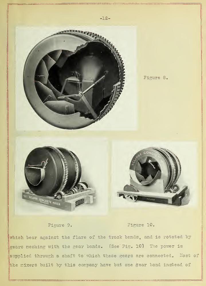
The drum is a "built-up cylinder of rolled plate steel.
(See Pig. 8) Two flanged steel heads being riveted to a shell,
which is reinforced by two heavy steel hands or rings with a flare
for the supporting rollers, and provided with gear teeth for
revolving the drum. (See Pig. 9). It is supported by guide rollers

-12-
Figure 9. Figure 10.
which hear against the flare of the track hands, and is rotated by
gears meshing with the gear hands. (See Pig. 10) The power is
supplied through a shaft to which these gears are connected. Most of
the mixers built by this company have but one gear band instead of


-13-
two. The size of the mixer determines the number to "be used.
On the interior surface of the drum are placed diagonal
vanes or blades at an angle to the central axis of the drum!. The
rotation of the drum throws the material against these blades, some
of which are placed in the center. The batch is thus thrown in a
longitudinal direction as well as stirred, which is conducive to a
thorough mixing.
The batch is discharged by a patented automatic device.
One of the blades is made long and is extended to the discharge
end of the mixer. A conveying chute extends into the head of the
drum at the discharging end. A shaft extending into the drum
supports a door which is held over the opening to the discharge
chute. The door is operated by handles at either end of the shaft
so that when the door drops down it closes a space between the
discharging end and a blade placed near the door. A pocket is
formed into which the concrete falls and is conducted from the mixer.
One of the chief advantages possessed by this mixer is
the low feed end. (See Fig. ll) The material has to be elevated
only a few feet which is a very important item in many instances.
Figure 11.


-14-
This mixer is very simple in design, and has the advantage of not
having a great many complex parts.
The feeding and proportioning of the material in mixing
concrete with this machine is the same as with the conical drum
type. V/ater is supplied by throwing into the mixer the required
amount, by hand.
CHICAGO MIXER.
A second representative type of cylindrical mixer is the
Chicago mixer, built by the Chicago Concrete Machinery Company of
Chicago. (See Fig. 12) This mixer differs fundamentally from the
Figure 12.
Eclipse in the different arrangement and form of the vanes, and the
method of discharging the batch.


-15-
In the cylinder of the Chicago mixer there are four
blades or inclined deflecting surfaces. (See Fig." 15 ) These blades
Figure 15.
are riveted to the inner surface of the drum and slope from the
discharge end towards the feed end. The vanes proper, or lifting
blades, are arranged in pairs. They lift the ingredients and drop
them upon the deflecting surfaces at the discharge end. The slope
of the deflecting planes cause the batch to be thrown towards the
center and to be lifted by the blades again.
The batch is discharged by a swinging spout projected
into the discharge end of the drum. The batch, falling upon this
spout from the lifting blades, is conducted from the mixer.
(See Fig. 14) During mixing the chute remains outside the drum.
This machine has a feed hopper which conducts the material
into the drum. (See Fig. 15) The same criticism as to the height
of the feed in the Snith mixer applies to this one. The material is
proportioned in the same manner and is fed to the machine as was
described for the Smith mixer.


-17-
7ater may be introduced into the machine in the ordinary
manner, or "by the use of an automatic tank "built "by this company to
be used with their machines.
It might he interesting to mention that a patented
distributing cylinder is built by this company to be used in
connection with their machine on street pavement work. (See Fig. 16)
Figure 16.
This cylinder is attached to the discharge end, and the batch
discharged directly into it. The cylinder is supported in a
horizontal position by a pivoted overhanging bracket. The concrete
is discharged by giving the cylinder a rotary motion.

-18-
MILWAUKEE MIXER.
In connection with the cylindrical type of mixer night
"be mentioned the Milwaukee mixer, built "by the Milwaukee Concrete and
Machinery Company, of Milwaukee. (See Fig. 17)
Figure 17.
The drum of this mixer is more nearly spherical in shape
than cylindrical. It differs from the two above discussed, in the
shape of the dritm, the form of the mixing vanes, and the drive.
The drum is made up of two halves bolted together.
[See Fig. 18) These halves are hemispherical in shape, and assembled
make a drum of spheroidal shape. (See Fe^r. 19)
Some of the vanes are built like scoops and are U shaped.


Figure 19.


-20-
They are "bolted to the shell of the drum from the.outside and
placed nearer the discharge end. The rest of the vanes are vertical
planes set at an angle to the main axis of the drum and placed nearer
the feed end. The material as it comes into the machine is thrown
"by these blades towards the center. The U shaped "blades catch it
and in turn drop it on the vertical "blades and the process is
repeated.
The batch is discharged by inserting an inclined chute
at the discharge end, into which the material is dropped by the
vanes. J See Pig. 20) The ingredients are proportioned and fed to
Figure 20.
the machine in the same manner as into the preceding mixers. Water
is supplied in the ordinary manner or by means of an automatic tank.
The height of the feed end of the machine is about the same as that
of the Chicago mixer and is open to the same criticisms.


Figure 21


-22-
CUBICAL DRUM.
The third type of revolving mixer is the cubical drum.
The drum of this type of mixer is built in the shape of a cube
and is rotated in a plane perpendicular to a long diagonal. Like
the conical drum mixer, this type is tilted to discharge the mixed
material. There are no blades or vanes fastened to the inner
surface of the drum. The mixing of the ingredients is done
entirely by the action of the flat surfaces of the sides of the
drum.
The principle of the mixing is that the flat sides of
the drum, as it is revolved, alternately carry the material back
and forth in the drum. The rapid shifting of the center of
gravity of the batch due to the cutting effect of the inclined
sides intermingles and mixes the ingredients.
AUSTIN CUBE MIXER.
A representative mixer of this type is that built by
the Austin Cube Mixer Company, of Chicago. (See Fig. 22)
The drum of this mixer is a square box with rounded
corners, built up of steel plates riveted together. (See Fig. 23)
It is revolved about a long diagonal by a gear band encircling it
at the center. This gear band is bolted to the drum and is
flared at one side for two guide rollers.' The drum is supported by
two large rollers at the ends. (See Fig. 24) These rollers in
turn run upon smaller rollers set in a square frame which is
suspended from two trunnions bearing in an A frame support. The


-25


-24-
Figure 24.
drum can be discharged while rotating, "by turning upon these
supporting trunnions. The drive shaft forms one of the trunnions
and a gear on this shaft meshes with the encircling gear "band of
the drum.
A flared steel spout is placed at the feed end of the
mixer and conveys the materials into the drum. (See Pig. 22)
There is the same objection to this mixer as to the conical drum
types with respect to the height of the feed end. In most cases
a platform will have to he "built at the feed end. The same methods
of proportioning and feeding as are used with the other types of
revolving drum mixers are used with this machine. Water may "be


-25-
introduced into the drum in the ordinary way or by an automatic
water tanlr. (See Fig. 22)
couraruous mixers.
A second general class of mixers is that in which the
feed into, and the discharge from the machine is continuous. This
method of mixing concrete is known as the revolving "blade, or
screw, or continuous process. The mixer usually consists of a long
narrow cylinder in which a screw shaft, or a central shaft having
a series of propeller "blades, operates. The material is put into
the machine at one end, and by the action of the shaft screw is
simultaneously stirred and carried towards the opposite end. Two
hoppers are usually placed at the feed end of the machine. One of
these hoppers has two compartments into one of which the sand is
placed and into the other, the cement. The other hopper holds the
gravel or crushed stone. The feed of the material from the hoppers
is regulated by automatic devices and in this way the correct
proportions of the batch are obtained. The rain shaft of the
machine is either connected to the driving shaft by a mesh of gears
or by a chain.
The principle of the mixing of the ingredients of this
machine is that the propeller blades of the main shaft will mix the
material as it carries it towards the end of the cylinder. The
average length of the cylinder is about seven feet.


-26-
EUREKA MIXER.
The Eureka mixer, built by the Eureka Machine Company,
of Lansing, Michigan, embodies most of the principles of continuous
mixers as discussed in the preceding paragraph. A brief
description will here be given. (See Fig. 25)
Figure 25.


-28-
The cylinder or trough of this machine is "built of
plate steel and is fastened to the supporting frame of the mixer.
A steel shaft having a set of propeller blades extends the entire
length of the trough. (See Pig. 26).
The "blades on this shaft are similar to screw propeller
blades and are inclined at an angle to the axis of the shaft so
that the shaft, when turning, causes the blades to act upon the
material in much the same manner as the propeller blades of a
steamship act upon the water.
The hoppers, into which the materials are placed and
through which they are fed into the machine, are placed near the
power end of the shaft. (See Fig. 27). The feed regulator is placed
in
Figure 27.


-29-
the bottom of the hopper and operated automatically. A four Lladed
shaft revolving in the "bottom of the hopper feeds the material
into the machine. (See Fig, 28) The amount of material fed into
Figure 28.


-30-
the machine is dependent upon the space between the "blades of the
feeder shaft. The space may be changed by adding or removing
filler plates which are bolted to the blades.
The sand and cement hopper is placed nearer the power
end of the machine. This permits a slight mixing of the sand and
cement before the gravel and water is added. The material is
stirred and churned by the revolving blades and carried forward to
the end of the through where it falls into the receiving cart or
barrow.
The shaft is driven by a chain connecting to a driving
shaft which in turn is belt driven. Any binding of the worm shaft
causes the belt to be thrown off and thus prevents any liability
of breakage due to the jamming of gravel between the sides of the
trough and the ends of the blades.
The height of the hoppers is such that the material
can easily be shoveled into them from the ground. The discharge end
is about three feet above the ground.
V/ater is added to the material in the form of a
spray. This spray is furnished by a small pump attached to the
mixer and can be automatically regulated by means of valves.
The capacity of the mixer is limited, in a way, by
the speed with which the material is taken to and from the machine.
T7ith the feeders on high speed the capacity is from 12 to 15 cu. yds.
per hour.


-31-
C0MPARIS01J OP BATCH AUD COIITIHUOUS TYPES OF MIXERS.
There is much difference of opinion among engineers as
to whether or not concrete can he mixed as thoroughly and he as
well proportioned by the continuous process as by the hatch method.
In the hatch process the material is folded over, cut
into, picked up and dropped by the action of the mixing vanes.
There is a constant turning over and intermingling of the materials.
In the continuous process the materials are mixed by
a set of blades chopping through them as they are pushed horizontally
through a distance of not more than 8 feet.
Under the same conditions it is obvious that the unit
cost of the mixed product is much less with a continuous mixer than
with a batch mixer. There is no time lost by the workmen waiting
for the machine to be emptied and recharged. The actual output
of both machines may be almost equal.
Of the two types of mixers, the first is the more simple
in design, and operation. There are not as many working parts and
they are not as intricate as in the continuous mixer.
It is claimed by the advocates of the continuous mixer
that the automatic proportioning device gives a more uniform concrete
than when the proportioning is done by hand. This is no doubt true,
but there is also a liability that the automatic feed may not do
its jork accurately, due to a clogging or jamming of its working parts.
The batch mixer is the more durable of the two types.
It is usually heavier and its parts are built more solidly than those


-32-
of the continuous. This weight is an advantage . in withstanding
hard and rough usage. 'j?here is less liability of "break downs due
to careless handling and continuous use.
With the batch type of mixer there is very little, if
any, probability of the drum binding in any manner, caused by the
material inside. In the case of the continuous mixer there is
always a possibility of the stone or gravel jamming between the
screw blades and the sides of the trough. To prevent breakage,
this is taken care of by a belt drive to the main shaft; the belt
slipping off when the shaft binds.
There are many instances where one of these two types
is more especially applicable than the other. In making cement
sidewalks or in other cases where but a small amount of concrete is
desired, it might be more advantageous to use the continuous type
of mixer as the mixer is light and can easily be moved about. The
cost of moving a heavy batch mixer a great many times, might easily
offset the other advantages of this type.
The batch mixer is used on almost all kinds of work.
The thoroughness and reliability of the mix makes it the best mixer
for all large works. It is usually placed at some central point
and the concrete d istributed by elevator and chutes which do away
with the necessity of moving the machine. Although a continuous
mixer may have just as large an output as a batch it is more seldom
used on important jobs ,than the latter.
With engineers, the batch type is by far the more popular,
and in some cases is required by the specifications for the contract.

-33-
HA1TD MIXERS OP THE BATCH TYPE.
In connection with this paper it might he interesting
to describe a hand machine mixer now on the market. The T.L. Smith
Company, of Chicago, build the machine. (See Pig. 29)
Figure 29.
This mixer, has a small cylindrical drum mounted on a
two wheeled truck and is revolved by turning a hand crank. This
crank is chain connected to a driving shaft which in turn is
connected by two chains encircling the drum. The drum or cylinder,
on the inside, has its ends sloping inward until they almost meet,
forming on the interior, two. wedge shaped chambers connected by a
slot extending diametrically across the drum. (See Pig. 30).
The cylinder is charged through an opening in the form of a small


-34-
Figure 30.
door, and is discharged in the same manner, (See Pig, 31)
. The revolving of the drum causes the materials to slide
toward the center and crowd through the narrow slot thus mixing
them together.
These machines are as efficient as the average hand
mixing method and are much easier on the workmen. They are

CO

-35-
especially suitable for small jobs such as sidewalks, steps, or such
work as might be required around a farm.
Figure 31.
GRAVITY MIXERS.
Among the many early methods of mixing concrete
mechanically, that of the gravity system deserves mention.
It was found that concrete might be mixed by permitting


-36-
the different ingredients to roll and fall down an inclined trough
studded with pegs, rr"he pegs caused the material to be nixed under
the action of gravity. A wide, shallow trough was used and the
material dumped in at the upper end and washed down with water.
The above is the simplest form used. Several improved forms were
later made hut all depended upon the force of gravity to mix the
ingredients.
Ihis is obviously an unsatisfactory method of nixing as
it is evident that the heavier particles tend to separate from
the finer and more light ones and does not produce a uniform concrete ,
CONCLUSION.
It has been the aim of the writer in this discussion,
to describe briefly the various methods of mechanical concrete
mixing, but more especially to give an impartial description of the
merits and faults of batch and continuous machine mixers. The
different factors that determine which of the two types of machine
should be used, have been briefly mentioned. It can not be said
of either, that it is the better of the two for all kinds of work.
It is the opinion of the writer, however, that the batch mixer is
more popular with engineers, and will eventually entirely, or almost
entirely, supersede the continuous mixer.