Embed Size (px)
Citation preview
A STUDY OF PERFORMANCE ANALYSIS OF FAN COIL UNIT
SYSTEM FOR FKM’S AIR CONDITIONER
NINA NADIA BINTI SAHIM
Report submitted in partial fulfillment of the requirements
for the award of
Bachelor of Mechanical Engineering
Faculty of Mechanical Engineering
UNIVERSITI MALAYSIA PAHANG
JUNE 2012

vi
ABSTRACT
Air conditioning system is a process of ventilation, air movement, air cleanliness,
dehumidifying and cooling in order to give comfort to occupant. In tropical climate
countries like Malaysia, air conditioner is very important to cool building space.
Currently, most of commercial building in Malaysia is equipped with air conditioner
either by using split unit or central unit types. Installation of air conditioner requires
heat gain estimation, so that the capacity of the installed air conditioner is suitable for
the particular area and gives the best performance in its operation. This project is carried
out to determine the heat gain and analyze performance of air conditioner at second
floor Block 2. FKM buildings start the operation in 2009. In 2009, every building in
FKM building is window glass single glazing without tinted film. Started from year
2011, those windows glass have been tinted to reduce glare and heat gain inside the
room. Besides that, factor of recommended setting temperature by Malaysia
government at 24 °C also affected the design of air conditioning system. Generally, the
main air conditioning system working at FKM is central air conditioning system. A
method has been implemented to obtain the heat gain which is cooling load temperature
difference/cooling load factor, (CLTD/CLF) while for cooling capacity, energy equation
throughout fan coil has been used. The heat gain study have been considered five rooms
in the second floor Block 2 (lecture rooms) which are Lecture Room 5 (BK 5), Lecture
Room 6 (BK 6), Briefing Room 8 (BT 8), Briefing Room 6 and 7 (BT 6 and 7), and
Discussion Room 6, 7 and 8 (BP 6, 7 and 8). From these five rooms, there are only two
rooms have been analyze the performance which are Bilik Kuliah 5 and Bilik
Taklimat 8. The study of heat gain is conducted from 8.00 am until 5.00 pm. The result
shows that the heat gains are 14.43 kW, 14.31 kW, 8.35 kW, 15.61 kW and 7.3 kW,
respectively. The percentage comparison heat gain against cooling coil load with load
for Briefing Room 8 and Lecture Room 5 are 34.45 % and 47.98 % less than the heat
gain by rooms. It happened because the data for cooling coil load were taken at steady
state condition, while the heat gain data were measured in unsteady state condition.
Thus, the fan coil still capable to cooled the rooms in steady state conditions.

vii
ABSTRAK
Penghawa dingin adalah sistem pengudaraan, gerakan kawalan dalam udara, kebersihan
udara, pengeringan dan penyejukkan bagi memberi keselasaan kepada penghuni. Di
negara-negara yg beriklim tropika seperti Malaysia memerlukan penghawa dingin bagi
menyejukkan bangunan. Kebanyakkan bangunan-bangunan komersial di Malaysia
dilengkapi dengan penghawa dingin sama ada menggunakan jenis pecahan penghawa
dingin atau pusat penghawa dingin. Pemasangan penghawa dingin memerlukan
penganggaran perolehan haba supaya kapasiti penyaman udara dipasang sesuai dengan
kawasan tertentu dan dapat memberikan prestasi yg terbaik. Projek ini dijalankan bagi
menentukan perolehan haba dan analisis prestasi penghawa dingin di aras dua blok dua.
Bangunan FKM memulakan operasinye bermula pada 2009. Pada tahun 2009, setiap
bangunan FKM menggunakan cermin tingkap tanpa lapisan filem. Bermula tahun 2011,
tingkap-tingkap kaca tersebut telah di lapiskan supaya dapat mengurangkan silau dan
haba dari memasuki bilik tersebut. Selain itu, faktor menetapkan suhu bilik yg
disarankan oleh kerajaan Malaysia kepada 24 °C juga akan mempengaruhi kepada reka
bentuk system penghawa dingin tersebut. Secara lazimnya, sistem berkerja bagi
penyaman udara di FKM yang utama adalah “central air conditioning”. Cara-cara untuk
mengetahui jumlah perolehan haba ialah mengunakan cara CLTD/CLF sementara bagi
mencari beban gelung penyejuk menggunakan persamaan penyejukan kapasiti.
Perolehan haba yang diperolehi pada waktu puncak untuk Bilik Kuliah 5 (BK5), Bilik
Kuliah 6 (BK 6), Bilik Taklimat 8 (BT 8), Bilik Taklimat 6 dan 7 (BT 6 and 7), dan
Bilik Perbincangan 6, 7 dan 8 (BP 6, 7 dan 8) adalah masing-masing sebanyak 14.43
kW, 14.31 kW, 8.35 kW, 15.61 kW dan 7.3 kW. Data bagi gegelung penyejuk telah
diambil di Bilik Kuliah 5 dan Bilik Taklimat 8. Peratusan perbezaan antara peroleh haba
dan gegelung penyejuk bagi kedua-dua bilk tersebut adalah sebanyak 34.45 % dan
47.98 % kurang daripada jumlah peroleh haba di bilik tersebut. Ini terjadi disebabkan
data bagi gegelung penyejuk telah diukur pada keadaan bilik sedang stabil sementara
peroleh haba diukur pada keadaan bilik tidak stabil.

viii
TABLE OF CONTENTS
Page
SUPERVISOR’S DECLARATION ii
STUDENT’S DECLARATION iii
DEDICATION iv
ACKNOWLEDGEMENTS v
ABSTRACT vi
ABSTRAK vii
TABLE OF CONTENTS viii
LIST OF TABLES xiii
LIST OF FIGURES xv
LIST OF SYMBOLS xvii
LIST OF ABBREVIATIONS xviii
CHAPTER 1 INTRODUCTION
1.1 Project Background 1
1.3 Problem Statement 3
1.3 Objectives of the Project 3
1.4 Scope of Project 4
1.5 Overviews of Report 4
CHAPTER 2 LITERATURE REVIEW
2.1 Introduction 6
2.2 Central Unit Air conditioning System 7
2.3 Type of Central Unit Air Conditioner 8
2.3.1 Direct expansion 8
2.3.2 Chilled water 9
2.4 Cooling Tower 11
2.5 Chillers 13
2.6 The Ideal Vapor Compression Refrigeration Cycle 14

ix
2.7 Cooling Load 15
2.7.1 CLTD, SCL and CLF concepts 16
2.7.2 Components of load 16
2.7.3 Cooling load/heat gain calculation concepts 17
2.8 FKM Air Conditioner System 23
2.8.1 Centrifugal chillers 23
2.8.2 Air handling unit 24
2.8.3 Fan coil 25
2.8.4 FKM chillers water working system 27
CHAPTER 3 METHODOLOGY
CHAPTER 4 RESULTS AND DISCUSSION
4.1 Introduction 40
4.2 Heat Gain Calculation 40
4.3 Peak Load Heat Gain 41
4.4 Analysis of Heat Gain 42
4.5 Performance Analysis System Air Conditioning 45
CHAPTER 5 CONCLUSIONS AND RECOMMENDATIONS
3.1 Introduction 29
3.2 Building Parameter and Design Criteria 29
3.3 Sample of Heat Gain Calculation 31
3.4 Parameters of Performance Analysis 36
3.5 Performance of Air Conditioning System 37
3.6 Sample of Cooling Capacity Calculation 38
5.1 Conclusions 51
5.2 Recommendations for the Future Research 52
REFERENCES
53

x
APPENDICES
A1 Cooling Load Temperature Difference (CLTD) from Sunlit Wall Type 54
A2 Cooling Load Temperature Differences for Conduction Through Glass 56
A3 U-Factors for Various Fenestration Product 57
A4 U-Factors of Doors 58
A5 Shading Coefficient of Single and Double Glazing
59
A6 Cooling LOAD Factor for Peoples 60
A7 Rate at Heat and Moisture by Human Beings with Different Activity 61
A8 Recommended Heat Gain from Typical Computer Equipment 62
A9 Ventilation from the Building 63
A10 July Solar Cooling Load for Sunlit Glass 40° North Latitude
64
A11 Typical Nonincandescent Light Fixtures 65
A12 Cooling Load factor for Lights 66
A13 Cooling Load factor for Equipments 67
A14 Thermal Properties of Layers Used in Walls 68
B1 Formula Heat Gains by using CLTD/CLF Method 69
B2 Heat gains from Conduction through Walls, Windows Glass, and
Doors at BT 8
70
B3 Heat gains from Conduction through Walls, Windows Glass, and
Doors at BK 5
71
B4 Heat gains from Conduction through Walls, Windows Glass, and
Doors at BK 6
72
B5 Heat gains from Conduction through Walls, Windows Glass, and
Doors at BP 6,7, and 8
73
B6 Heat gains from Conduction through Walls, Windows Glass, and
Doors at BT 6 and 7
74

xi
B7 Heat Gains from Solar Radiation at BT 8 75
B8 Heat Gains from Solar Radiation at BK 5 76
B9 Heat Gains from Solar Radiation at BK 6 77
B10 Heat Gains from Solar Radiation at BP 6,7, and 8 78
B11 Heat Gains from Solar Radiation at BT 6 and 7 79
B12 Heat Gains from Lighting at BT 8 80
B13 Heat Gains from Lighting at BK 5 and 6 81
B14 Heat Gains from Lighting at BP 6, 7, and 8 82
B15 Heat Gains from Lighting at BT 6 and 7 83
B16 Heat Gains from Peoples and Appliances at BT 8 84
B17 Heat Gains from Peoples and Appliances at BK 5 and 6 85
B18 Heat Gains from Peoples and Appliances at BP 6,7, and 8 86
B19 Heat Gains from Peoples and Appliances at BT 6 and 7 87
B20 Heat Gains from Ventilation BT 8 88
B21 Heat Gains from Ventilation at BK 5 89
B22 Heat Gains from Ventilation at BK 6 90
B23 Heat Gains from Ventilation at BP 6,7, and 8 91
B24 Heat Gains from Ventilation at BT 6 and 7 92

xii
LIST OF TABLES
Table No. Titles Page
3.1 FKM building specification for walls 33
3.2 Wall total resistance 33
3.3 CLTD for North West and South East Direction 34
4.1 Data of heat gain 41
4.2 Comparison value of cooling coil and heat gain room 45
4.3 Comparison value of cooling coil and heat gain room with load 49

xiii
LIST OF FIGURES
Figure No. Titles Page
2.1 Fan coil unit air conditioning system 7
2.2 Direct expansion air conditioning system 9
2.3 Chilled water central air conditioning plant 10
2.4 Recirculation water system using a tower
11
2.5 Cooling tower
12
2.6 Packaged water chiller 13
2.7 Schematic and T-s diagram for the ideal vapor-compression
refrigerant cycle
14
2.8 Centrifugal chiller in FKM building 24
2.9 Air Handling Unit in FKM building 25
2.10 Fan coil system
26
2.11 System flow of FKM central unit air conditioning 27
3.1 Plant layout room 30
3.2 Experimental device for heat gain 31
3.3 Experimental device for cooling capacity 37
4.1 Internal and external heat gain at different rooms at 3.00 pm 42
4.2 Heat gain contribution through exterior structure for BK 5 43
4.3 Heat gain contribution through internal structure for BK 5 45
4.4 Comparison heat gain and cooling capacity with load 46
4.5 Comparison heat gain and cooling capacity (without load) 46
xiv
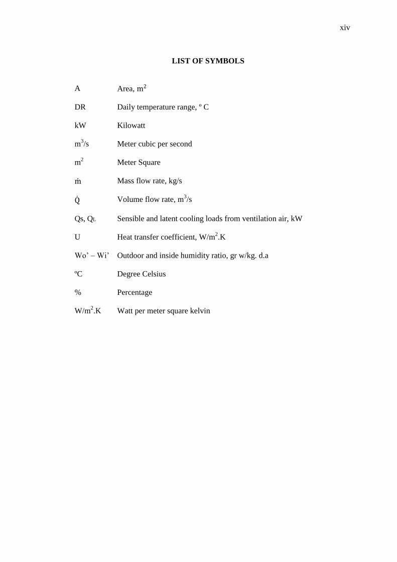
LIST OF SYMBOLS
A Area, m2
DR Daily temperature range, º C
kW Kilowatt
m3/s Meter cubic per second
m2 Meter Square
m Mass flow rate, kg/s
Q Volume flow rate, m3/s
Qs, QL
Sensible and latent cooling loads from ventilation air, kW
U Heat transfer coefficient, W/m2.K
Wo’ – Wi’ Outdoor and inside humidity ratio, gr w/kg. d.a
ºC Degree Celsius
% Percentage
W/m2.K Watt per meter square kelvin

xv
LIST OF ABBREVIATIONS
LHG Latent heat gain
HVAC Heating, ventilating and air conditioning
FKM Fakulti Kejuruteraan Mekanikal
FCU Fan Coil Unit
CLTD Cooling load temperature difference
DX Direct Expansion
CLF Cooling load factor
B.F Ballast factor
ASHRAE American Society of Heating, Refrigerating and Air Conditioning
Engineer
AHU Air Handling Unit
BT Briefing room
BK Lecture room
BP Discussion room

CHAPTER 1
INTRODUCTION
1.1 PROJECT BACKGROUND
Air conditioning can be refer as any form of cooling, ventilation or disinfection
that modifies the condition of air, humidity and air cleanliness that controlled within
limits determined by the requirements of the air conditioned enclose (Hundy et al.,
2008). In modern society, air conditioners are commonly found in homes, schools,
offices, vehicles and public enclosed spaces due to the demand for thermal comfort.
During hot weather, it is very important for human to feel comfortable and healthy
indoor environment in which to carry out their activities by using an air conditioner.
The actual process of air conditioner is to reduce the ambient air temperature in a room
based on a simple scientific principle. The rest is achieved with the application of a few
clever mechanical techniques.
There are various types of air conditioning systems, such as window air
conditioner, packaged air conditioner, split air conditioner and central air conditioner.
There are some factors to consider choosing best air conditioning unit like how large the
area to be cooled and total heat generated inside the enclosed area. The basic air
conditioning system is working based on vapor-compression refrigeration cycle which
consists of an evaporator, a condenser, a compressor and a metering device. In the
vapor-compression refrigeration cycle, heat is transferred from a lower temperature
medium to a higher temperature heat sink. From the second Law of Thermodynamics,
heat naturally flows in a certain direction and not in the reverse direction which is heat
will be moved through spontaneous flow of heat from hot to cold (Cengel and
Boles, 2006).

2
Most of commercial building in Malaysia is equipped with air conditioner
because of Malaysia is located in hot climate countries. This is included building for
Faculty of Mechanical Engineering (FKM), Universiti Malaysia Pahang in Pekan,
which started it operation in July 2009. In general, the building is divided into 5 blocks
which are consists of Block 1, Block 2, Block 3, Block 4, and Admin Block. Each block
will get different amount of cooling load of air conditioning due to factor of people in
the cooled space, equipment inside the space, heat leakage from the outside leaks
through door, windows, and other potential factors. Block 1, 2 and 3 are consist of
laboratories, preparation rooms and lecturer rooms, meanwhile Block 2 consists of
lecture block, 2 laboratories and few rooms for lecturer. The lecture block consists of
six lecture rooms with 60 person capacities of each, 8 tutorial rooms and 9 discussion
rooms. All rooms in the lecture block are provided with air conditioner.
The main air conditioner at FKM is central type air conditioning system. The
central air conditioning plants or the system is used when large buildings are to be air
conditioned completely. Central air conditioner units operate with energy moving or
converter machines that are designed to cool or heat the entire building. The machine
does not create heat or cool, but it just removes heat from one area, where it is
undesirable, to an area where it is less significant or makes no difference. In FKM
building, chilled water and cooling tower also plays important role in order to support
central air conditioner to give people’s comfortability in their room. Chilled water
system for FKM building consists of 4 nos. of chiller, 4 nos. of cooling tower, 4 nos. of
chilled water pumps, and 4 nos. of condenser water pump. The cooling tower is placed
on of chiller water plant room while the chillers and pumps are placed at ground floor
(Hamzah, 2011).
Since FKM starts operate in July 2009, unpredictable performance is a common
problem in air conditioner that always occurs. Since the system has been introduced,
performance of the system will be the main issue and the problem needs to be solved as
soon as possible in order to get the best performance of air conditioning system at FKM
building. Besides that, the building in this faculty has been modified from window
glazing without tinted into window glazing with tinted. In addition, government also
decided temperature of all government’s building must be regulated to be set at 24 °C.

3
1.2 PROBLEM STATEMENT
In the FKM building, air conditioning uses more electricity energy than others
appliances. Reducing of air conditioner temperature will consumes more energy. It has
been mentioned that the FKM building started it operation since July 2009. In early of
2011, the buildings in this faculty have been modified in form of window glazing with
tinted. Thus, it will effect to radiation of heat gain and also original design of heat gain
in the particular room. Windows glazing with tinted will reduce the amount of heat gain
by radiation into the rooms without reducing the light receive. Therefore, new heat gain
calculation is crucial to be obtained and air conditioning system performance as well.
Besides the modification of windows glass with tinted that will reduce amount of heat
gain into the building, fixing of temperature setting also gives a effect to the
performance of air conditioning system. Fixing of temperature setting has been decided
by government on 12 August 2011 which encourage all government offices have been
ordered to set the air conditioner temperature no lower than 24 °C in order to give
nature a helping hand and to save electricity energy (Ahmad, 2011). Air conditioning
setting temperature at 24 °C gives less amount of refrigeration capacity and also
affected original design of air conditioning system in term of air handling unit (AHU)
and chiller plant. Therefore, the amount of refrigeration effect needs to be recalculated
to fix with air conditioner setting temperature of 24 °C. This work also can resize of
component of air conditioning used in the building.
1.3 PROJECT OBJECTIVES
This study was conducted at eight locations at second floor block 2 at FKM
building. The objectives of this study as follows:
(i) To investigate the heat gain in the second floor Block 2 of FKM building.
(ii) To analyze performance of air conditioning system for Lecture Room 5 and
Briefing Room 8 at FKM buildings.
4
1.4 PROJECTS SCOPES
Based on the objectives of this project, there are four scopes in this project in
order to meet with the project objectives that have been addressed in previous section.
The scopes are as follows:
(i) Fundamental study of central unit air conditioning system applied at
FKM.
(ii) Carry out heat gain calculation generated in the particular room by using
Cooling Load Temperature Different/Cooling Load Factor (CLTD/CLF)
method.
(iii) Carry out data collection or measurement of the air conditioner in the
particular rooms related to temperature inside the room and also to
supply and return air velocity.
(iv) Carry out performance analysis fan coil (FCU) by using energy equation.
1.5 OVERVIEWS OF REPORT
Chapter 1: Chapter 1 is generally discuss about the function of air conditioning system.
This chapter also explains types of air conditioner according to the suitable rooms. It
also provides the problem statement, objectives, and scopes of the project in order to
complete the research.
Chapter 2: In this chapter, it discuss about the literature review of the air conditioning
system which is Central unit air conditioning. This chapter also explains more details
about working principle of air conditioning system. Beside, the suitable method to
obtain heat gain and cooling capacity in particular room also has been discussed. There
are three subchapters on literature review such as central air conditioning system,
cooling load concept, and FKM air conditioning system. All of these subchapters need
to be study in order to gain idea and understanding the system of an air conditioning.

5
Chapter 3: Chapter 3 discuss details about the methods of experiment. In this chapter,
it divided into two experiments which are heat gain and cooling capacity of particular
rooms. Heat gain in the particular room can be determined by using CLTD/ /CLF
method. While, energy equation are used in order to find cooling capacity for chiller
plant system.
Chapter 4: The final outcome reaches in better result if the calculation performance of
chiller plants gives in higher value than the cooling load calculation. This will give
impact to the people in the room to be more comfortable since the result shows that the
each components of the chiller are in good efficiency. The analysis and discussion can
be defined from the results. The several factors influence the results can be obtained
from the results such as position of the room relative to solar orientation, electric
appliances, number of people in the room, wall material, windows material, and other
potential factors. All of these factors are dividing into two parts which are external heat
gain and internal heat gain. The total sensible heat can be determined from detail
analysis.
Chapter 5: In this chapter, it discuss about the conclusion of this project. Conclusion is
important in order to make sure the objectives are achieved. It also comes out with final
results of this research.

CHAPTER 2
LITERATURE REVIEW
2.1 INTRODUCTION
The development of air conditioning is one of the greatest engineering
achievements of the 20th
century. The temperature of a room or building can be easily
modified and controlled by using a modern air conditioning. In harsh climates, an air
conditioner allows people to live more comfortable without thinking about hot weather.
In this chapter, concepts of performance and operation system of air conditioners have
been thoroughly discussed and were divided into three subchapters which are
fundamentals of central unit air conditioning system, FKM operation system, and
concepts of cooling load. The objectives of this project can be achieved by studying and
analyzing all of the references that have been done by professionals in the air
conditioner field. All of these subchapters will be explain more detail based on referring
to ASHRAE Fundamentals, journal, article, and others. Generally, there are various
types of air conditioner have been used around the world such as window air
conditioner, packaged air conditioner, split air conditioner and central air conditioner.
However, this chapter will be focusing on central unit air conditioner which suitable for
large building. This is because only this type of air conditioner is being used at FKM.
For evaluating and checking the performance of central unit, CLTD/CLF method will
be used in this project.

7
2.2 CENTRAL UNIT AIR CONDITIONING SYSTEM
Central air conditioning system also known as central system are designed to
cool or heat the entire building by removing heat from one area to another area where it
is less significant or makes no difference (Hundy et al., 2008). Central air conditioning
plants are used for large building and it is very efficient to make the entire room to be
air conditioned completely and successfully. In the central air conditioning systems
there is a plant room where large compressor, condenser, expansion valve, and
evaporator are kept. All of the function will be perform as usual similar to a typical
refrigerator system but all these parts are larger in size and have higher capacities.
The FKM’s central unit air conditioning system is divided into three parts
system. The first part is a central plant in which a boiler and chillers are located. The
second part is a water system which the function is to remove heat and to produce
chilled water from the central plant to the heat exchanger unit and lastly, the third is a
cool air supply system. The cool air supply system is using Fan Coil Unit (FCU) for
lecture block in Block 2. The function of FCU is to prepare the mixture of outdoor air
and recirculation air from the conditioned room and resupply the mixture of air to the
space or room to be cooled. In a central air conditioning system, air is heated or cooled
by the hot or chilled water from chiller plant that flows in FCU’s coil. Conditioned air
will be passing through ducts, terminals, and diffusers (Chadderton, 1997). Figure 2.1
shows working system of fan coil unit air conditioner.
Figure 2.1: Fan coil unit air conditioning system
Conditioned supply air
Access panel Recirculation air
grille
Hot and chilled
water flows and returns
Linear diffuser
Conditioned fresh air duct Fan coil unit Plenum

8
All type of air conditioner have the same principle when cooling the air with one
propose that is converting and changing hot air into cool air. The cycle is closely similar
to refrigeration system but is more purposed to cool large building. The key of the
converting process is compressor cycle. The system will transfer the heat from inside to
outside of the building in order to make people feels comfort during hot weather. In
fact, central air conditioners always work more quietly than other types because of the
condenser and compressor is usually installed at outside of the building.
There are three main parts in this working principle like compressor, condenser,
and evaporator. Air conditioning compressor is the heart of the air conditioner units.
The air conditioner compressor is responsible to compress the low pressure and low
temperature of Freon gas to higher pressure and temperature before entering the
condenser. Then the high pressure gas will be directly gone into coils of the condenser.
The condenser is a heat transfer device which is located outside of the cooled space.
The gas is condensed into a liquid by dissipate the heat. The liquid become cooler after
going through the thermodynamic process in condenser. Then, the liquid will fed into
evaporator by going narrow hole to decrease the pressure of the liquid and at the same
time the process of producing cold gas is also started. The cold gas will be pushed out
from the air conditioning unit to be distributed to all space of the room via ducts. The
blower sucks the hot return air via ducts and blow into cooling coil. The system will
always continue repeating.
2.3 TYPE OF CENTRAL UNIT AIR CONDITIONER
There are two general types of central air conditioner like direct expansion and
chilled water. The concepts of operating system will be discussed below in further
details.
2.3.1 Direct Expansion
In direct expansion or DX types of air central conditioning plants, the air used
for cooling the room or space is directly passed over the cooling coil at the refrigeration
plant. The efficiency of the DX plants is higher due to the air is cooled directly by the

9
refrigerant. It is suitable for cooling the small building because it is not always feasible
to carry refrigerant piping to the long distance (Balamugundan, 2008). In this system,
there are two rooms. The first room consists of huge compressor, and the condenser
which is called as plant room. For the second room known as air handling unit room
consists of expansion valve, evaporator or the cooling coil, and the air handling unit.
Figure 2.2 shows the layout of direct expansion air conditioning system. Inside the air
handling unit, large blower house is in it while the cooling coil is fixed in the air
handling unit. The function of blower is to sucks the hot air from the room via ducts and
blows it through the cooling coil. After that, the cooled air will be supplied through the
ducts into the rooms. This system will have higher efficiency if the area of the building
is not too large (Shan, 2001).
Figure 2.2: Direct expansion air conditioning system
2.3.2 Chilled water
The chilled water types of central air conditioning plants are very suitable for the
large building which is has several floors like hotel, shopping mall, and so on. The
different system operation of chilled water system compared to direct expansion system
is the working principle. The chilled water system is shown in Figure 2.3.
Make up and fill
connection
Drain
C.tower
Cond water pump
Fresh air duct with
damper
Plant room
Compressor
Cond Air conditioned room
Supply air duct Return air
duct
Thermostatic
expansion valve
Liquid line
strainer
AHU room S.A diffuser
R.A diffuser Fan Coil

10
Figure 2.3: Chilled water central air conditioning plant
In chilled water plants, the water or brine solution is chilled to very low
temperatures of about 6 to 8 °C by the refrigerant plant (Miller and Miller, 2006). The
chilled water is pumped to various floors of the building which air handling units are
installed. In this system, the type of evaporator that being used is a shell and tube. On
the shell side the brine solution is passed while the other side the Freon fluid passes at
extremely low temperature. The temperature of brine solution will drop after going
through the evaporator and is pumped to cooling coil in air handling unit at every floors.
Generally, in air handling unit comprises of the important part such as blower, cooling
coil, and the ducts. The blower sucks the hot air via ducts and passes over the cooling
coil and gets cooled. After that, the air is then passes to the air conditioned space
through various ducts.

11
2.4 COOLING TOWER
A cooling tower is a heat rejection device, extract waste heat to the atmosphere
in order to cool the room. Cooling towers are used to recover or preserve water in air
conditioning system. Hot water from the condenser will pump to the cooling tower
which is it will spray into the tower basin. The temperature of the water will be decrease
after the water passing through the tower. When the wet-bulb temperature of the
incoming air is decrease, the efficiency of the air will be increased in order to decrease
the temperature of the water being fed into the tower (Miller and Miller, 2006).
Figure 2.4 shows recirculation water system using cooling tower. There is several
factors influence the efficiency of the cooling tower
(i) Mean difference between vapor pressure of the air and pressure in the
tower water.
(ii) The amount of water surface exposed to air and the length of exposure
time of the water to the air.
(iii) Direction of airflow relative to the exposed water surface whether it
parallel, transverse or counter.
Figure 2.4: Recirculation water system using a cooling tower

12
Theoretically, the lowest temperature to which the water can be cooled is the
temperature of the air (wet bulb) entering the tower. However, it is impossible for the
temperature of the water at exit tower to reach the same temperature like of the air. The
temperature of the water normally higher than the air temperature which are the
temperatures are around 4 to 6 °C (Miller and Miller, 2006).
Cooling tower can be classified into three parts such as counter-flow induced-
draft, cross-flow induced-draft, and counter-flow forced-draft. In a counter-flow, air
motion is opposite to the downward motion of the water which the air will travels
upward through the fill while the cross-flow, motion of the water is downward and air
moves horizontally through the fill. The fan both of these types is located down-stream
from the fill at the air exit. However, there are differ in performance of tower which is
the counter-flow arrangement performance is higher than cross-flow arrangement
performance (Shan, 2001). Figure 2.5 shows classification of cooling tower.
Figure 2.5: Cooling tower
(a) Counter-flow
induced-draft
(b) Cross-flow
induced-draft
(c) Counter-flow
forced-draft
Drift
eliminator
Propeller fan
Air
To condenser or coil
Fill Air intake
Propeller fan
Water
basin
To condenser
or coil
Air intake
Fill Fill
Water distribution
system
To condenser
or coil
Centrifugal
fan
Drift
eliminator Condenser water
Makeup water
Air
Fill

13
2.5 CHILLERS
In a modern central unit air conditioning system, chiller is used as to cool water
or brine solutions. After the water or brine solution cooled, it will feed through pipes to
evaporators. In generally, the preferred secondary refrigerant will be water. The water
can be circulated without risk of freezing even though the load temperature is
sufficiently above 0 °C. In generally, chilled water for an air conditioning systems need
the temperature of water is not lower than 5 °C.
A chiller is a machine that removes heat from a liquid via a vapor-compression
or absorption refrigeration cycle. There are basically five different types of chillers such
as reciprocating compression, scroll compression, screw-driven compression, and
centrifugal compression. Chiller can be water-cooled or air-cooled. A chilled water
system provides chilled water for cooling purposes to all air conditioner equipments like
AHU. The number of chillers in a building depends on the maximum expected cooling
load in that particular building. Figure 2.6 shows packaged water chiller (Trot and
Welch, 2000).
Figure 2.6: Packaged water chiller
(a) Air-cooled (b) Water-cooled