Embed Size (px)
Citation preview
A Study of Phased Array Antennas for NASA’s Deep Space Network
V. Jamnejad, J. Huang, R. J. Cesarone Jet Propulsion Laboratory, California Institute of Technology
4800 Oak Grove Drive Pasadena, CA 9 1 107
Abstract: Recently, the Jet Propulsion Laboratory (JPL) has begun an assessment of the long-term capability of the antennas of the Deep Space Network (DSN). Various alternative plans for upgrading or replacing the present 70-meter antennas have been considered. Several options have been studied which include modifying the present antennas for extended life and reliability, new 70-meter single aperture antennas with offset or symmetric feeds, 100-meter spherical antennas, an array of a few smaller 34-meter antennas, a much larger array (hundreds) of much smaller (5-10 meter) reflector antennas, and finally active planar phased arrays with millions of elements. In this paper we briefly discuss various options but focus on the feasibility of the phased arrays as a viable option for this application. Of particular concern and consideration will be the cost, reliability, and performance compared to the present 70-meter antenna system, particularly the gaidnoise temperature levels in the receive mode. Many alternative phased arrays including planar horizontal arrays, hybrid mechanically/electronically steered arrays, phased array of mechanically steered reflectors, multi-faceted planar arrays, phased array-fed lens antennas, and planar reflect-arrays are compared and their viability is assessed. Although they have many advantages including higher reliability, near-instantaneous beam switching or steering capability, the cost of such arrays is presently prohibitive and it is concluded that the only viable array options at the present are the arrays of a few or many small reflectors. The active planar phased arrays, however, may become feasible options in the next decade and can be considered for deployment in smaller configurations as supplementary options.
1. Introduction
The foreseeable future of Solar System exploration includes a number of trends that are expected to place strong customer demands on the facilities of NASA’s
Deep Space Network. These trends comprise the following: a migration of the exploratory spacecraft fleet further out into space; a consequent growing reliance on large aperture ground antennas; a rapid growth in the data rate capabilities of science instruments and public media formats, and; a need for long-haul trunk lines resulting from the emplacement of planetary local area networks, especially at Mars. Though these trends emerge primarily from analysis of NASA’s Space Science Enterprise robotic mission model, they also apply to the future missions of the Agency’s Human Exploration and Development of Space Enterprise.
Recently, JPL was tasked by NASA, to examine the potential future need for large aperture radio frequency antennas. Motivation for the task was not only the normal process of long-range (strategic) planning, but also the aging of the large, 70m diameter antennas of the DSN. Specifically, answers to two questions were sought. Will the level of capability, currently afforded by the 70 m antennas, still expected to be needed in the future? And if so, what is the best way to provide such a capability? The answer to the first question was an unequivocal “Yes,” as evidenced by the mission set trends described above. In particular, two of the four themes of the Space Science Enterprise were seen as the strongest drivers. The final answer to the second question is still pending and does not in fact need to be decided until such time as implementation commitments are required. However, work to date has examined seven alternatives, described briefly as Options A - G.
Option A entails modifications to the existing 70m antennas to assure extended life and reliability. These assets were originally constructed as 64m antennas in the late-1960s and early-l970s, and were designed for a 10-year lifetime, running at - 25% duty cycle. The antennas are currently on the order of 30 years old, and for much of their lifetime have run at - 80% duty cycle. For the benefit of the Voyager Mission, they were upgraded to 70m diameter in the late-l980s, which added significant mass to the load-bearing elements. So it is not surprising that wear-and-tear and future reliability are matters for concern. The option identified a number of structural and mechanical modifications to these antennas that will be needed to assure reliable operations for the future. Also, to minimize costs, no new capabilities were assumed.
Option B is essentially the same as Option A but with the addition of a Ka-band receive capability. Though X-band (8 GHz) has been the nominal frequency band for deep space communications for 20 years, and S-band (32 GHz) before that, there is a strong push to move up to higher frequencies. Rationales include the enhanced directivity and gain (- 6 dB, after accounting for all losses) afforded by the higher frequency plus the factor of 10 increase in allocated bandwidth.

Option C entails implementation of new - 70m single aperture antennas, nominally one per DSN complex. As single aperture, monolithic antennas, these would follow in the tradition of the existing 70m antennas. However, they would use the latest technology to enable high-performance operations at Ka-band frequencies. Antennas would be expected to utilize wheel & track for azimuth motion and actuated panels to maintain surface precision. Traditional designs with Cassegrain feeds and beam wave guide optics were investigated, as well as ones with a clear-aperture, offset feed, as in the recently commissioned 100m Green Bank Radio Telescope. For the purposes of the study, a 70m diameter was used as the baseline for comparison. However, there is no reason why larger diameter single aperture antennas could not be built should that choice be taken by the Agency.
Option D involves an array of four 34m diameter antennas to equate to the aperture of a single 70m antenna. 34m antennas are the current workhorses of the DSN, most often used in the configuration of a single antenna per spacecraft. There is however, significant experience in arraying 34m antennas together, or with 70m antennas, to track especially weak signals. Thus it is logical to consider such an option. However, all previous arraying experience within the DSN has been in the downlink configuration only. Uplink arraying, at this point, is still considered to be a technology development activity. As such, feasibility of this option, as a full function replacement for current 70m capability, is not yet demonstrated.
Option E proposes use of an array of - 5m aperture antennas to synthesize the equivalent aperture of a 70m antenna. In essence, it is a large array of small antennas rather than a small array of large antennas, as in the previous option. This option has much in common with recent trends in the radio astronomy community, where arrays are quite popular, not only for their signal sensitivity, but also for their angular resolution. In fact, proposers of this option arc working closely with the Square Kilometer Array (SKA) initiative that has been recommended as a high priority in the Astronomy & Astrophysics Decadal Report. It is envisioned that the many small parabolas needed can be manufactured, and outfitted with electronics, relatively inexpensively. Side benefits include the prospect of multi-beaming, at least within the field-of view (FOV) of any given dish. Issues include, as for the previous option, the need to provide for an arrayed uplink.

Option F carries the arrayed concept one step further still by postulating the creation of electronically-steered, phased-array, flat plate antennas. For this option, the individual antenna elements are quite small and there can be many millions of them. Although such antennas have been constructed for various applications over the years, they have never been used for long-haul deep space communications, at the frequencies of interest, and with all the attendant requirements. Significant benefits may include instantaneous and simultaneous beam-forming that can lead to new modes of deep space operations - in effect a demand, rather than scheduled, DSN. Also elimination of the need for many moving parts can yield significant reductions in long-term operating costs. But there are many challenges as well, both technical and economic, that would have to be overcome to successfully implement such a concept. These will be discussed at some length in this paper.
Option G is an innovative idea called the SPHERE (Spherical Pair of High - Efficiency geflecting Elements) concept. Here the idea is to construct an antenna pair, where each element rotates only in azimuth, never in elevation. Because elevation is fixed, gravity-induced surface deformations will not be a concern. One of the pair would cover low elevation angles whereas the other would provide the complementary high elevation coverage. Elevation pointing would be effected by motion of the prime focus feed assembly, as in the Arecibo Radio Telescope. This option has shown promise and will be considered as a candidate for technology development.
Given the lead time required for government budget planning and construction of facilities processes, plus actual implementation, it is reasonable to expect that another 10 years, minimum, of age will accumulate on the existing 70m antennas before an actual replacement capability could be on line. Thus it became evident that some part of Option A will be needed regardless of which option is finally selected. Consequently the recent budget submission reflected this need and is expected to be viewed favorably.
In this paper we will focus on a number of array options (including E, F, and G) and outline some of the issues associated with these options and provide recommendations for further study.
2. Phase Arrays
Phased array antennas composed of a number of smaller antenna elements provide an attractive alternative to the conventional single reflector systems for
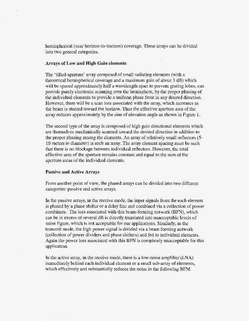
hemispherical (near horizon-to-horizon) coverage. These arrays can be divided into two general categories.
Arrays of Low and High Gain elements
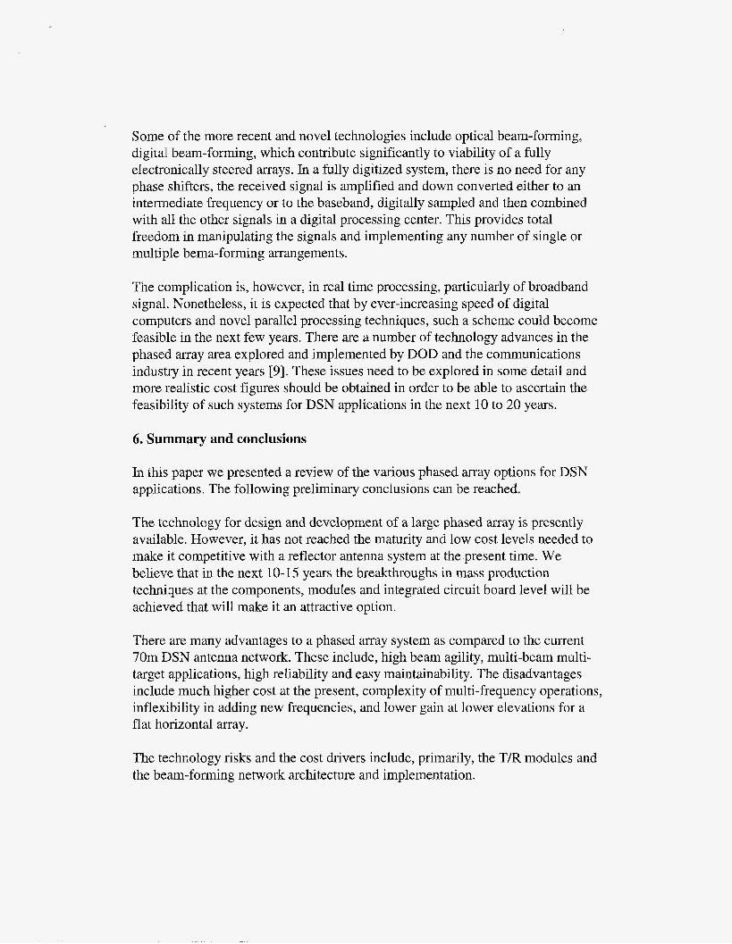
The ‘filled-aperture’ array composed of small radiating elements (with a theoretical hemispherical coverage and a maximum gain of about 3 dB) which will be spaced approximately half a wavelength apart to prevent grating lobes, can provide purely electronic scanning over the hemisphere, by the proper phasing of the individual elements to provide a uniform phase front in any desired direction. However, there will be a scan loss associated with the array, which increases as the beam is steered toward the horizon. Thus the effective aperture area of the array reduces approximately by the sine of elevation angle as shown in Figure 1.
The second type of the array is composed of high gain directional elements which are themselves mechanically scanned toward the desired direction in addition to the proper phasing among the elements. An array of relatively small reflectors (5- 10 meters in diameter) is such an array. The array element spacing must be such that there is no blockage between individual reflectors. However, the total effective area of the aperture remains constant and equal to the sum of the aperture areas of the individual elements.
Passive and Active Arrays
From another point of view, the phased arrays can be divided into two different categories: passive and active arrays.
In the passive arrays, in the receive mode, the input signals from the each element is phased by a phase shifter or a delay line and combined via a collection of power combiners. The loss associated with this beam-forming network (BFN), which can be in excess of several dB is directly translated into unacceptable levels of noise figure, which is not acceptable for our applications. Similarly, in the transmit mode, the high power signal is divided via a beam forming network (collection of power dividers and phase shifters) and fed to individual elements. Again the power loss associated with this BFN is completely unacceptable for this application.
In the active array, in the receive mode, there is a low-noise amplifier (LNA) immediately behind each individual element or a small sub-array of elements, which effectively and substantially reduces the noise in the following BFM
composed of phase shifters and power dividers. Similarly, in the transmit mode, the low power signal is divided by the BFN composed of power dividers and phase shifter and then fed to the individual elements (or sub-array of elements) via a High Power Amplifier (HPA). Thus only a minimal amount of power is lost at the power dividers and phase shifters. Furthermore, instead of requiring a very high power generatodamplifier, the power amplification is distributed over the entire array. In a combined transmitlreceive array, the HPA and ENA behind the elements are combined to form a T/R module which also includes a diplexer to isolate the transmit and receive paths.
3. Advantages and Disadvantages of Phased Arrays
Phased array antennas provide certain advantages over conventional reflector systems. There are, of course, certain disadvantages as well, which should be taken into consideration in deciding a technically feasible and economically viable solution in the context of a near future or a longer-term (10-20 yrs) antenna system for the Deep Space Network (DSN).
Some of the advantages of a phased array are:
- Beam agility: The antenna beam can be moved almost instantaneously to any desired direction, a feat that cannot be accomplished by a mechanically steered reflector antenna system.
- Reliability and graceful degradation: A phased array, composed of a large number of radiating elements, is a more reliable system in the sense that in the event of the failure of some or many of its elements, it can still operate with various degrees of capability, namely, with a graceful degradation. While any malfunction in a single reflector antenna system, brings the operation of the whole system to a halt. This could have major implication in critical usage scenarios.
- Maintainability: A related issue is the question of maintainability. In a phased array failure of certain element can be addressed, and fixes and routine maintenance can be applied, while the overall system is operating. By contrast, in a single reflector antenna system, the operation of the system must be stopped in order to provide for the necessary fixes and refurbishments of the system. Lack of mechanical motion: This applies only to the filled aperture phased arrays in which there are no moving parts and all beam steering is provided strictly electronically. This eliminates the possibility of mechanical breakdown and reduces maintenance costs.
- Multiple beam operation capability: The phased array provides the ability to provide simultaneous multiple beam operations which can be useful in certain situations involving multiple spacecraft at different positions. This is achieved at the expense of a complicated beam-forming network.
- Lower long term maintenance cost: Due to the lack of any complicated moving mechanical parts as in reflector antennas of the DSN, which require constant maintenance and repair, the long term cost of a fully electronic phased array system is expected to be substantially lower than its mechanical counterpart.
Some of the disadvantages of the phased array are:
- Beam-forming network complexity: This is perhaps the most significant drawback of a conventional phased array system. The implementation of dividing and /or combining signals from thousands or millions of elements is a daunting task with major architectural and layout complications. This becomes an even harder task to accomplish in a multiple beam implementation. A digital beam- forming and processing scheme may reduce some of these complications but is nonetheless far more complicated than a relatively simple reflector antenna system.
- Limited multi-frequency operation capability: The phased array systems are inherently narrow-band. The situation can be somewhat mitigated by appropriate beam-forming architecture and the use of true time-delay elements. The array operation can be extended to multiple frequencies by stacking or interleaving array elements at two or more frequencies (for example at X and Ka bands).
- Lack of flexibility in adding new capabilities (additional frequencies, etc.): Any change in operational frequency band would require a change in all the array elements in contrast to a reflector system where only a single feed for the entire system needs to be modified or replaced.
- Poor performance of single planar array at low elevation angles As previously mentioned, in a single horizontal planar aperture array, as the beam scans from zenith, the effective aperture area of the array reduces approximately by the sine of elevation angle as shown in Figure 1.
- Pattern anomalies With phased arrays there are possibilities for generating spurious grating lobes and blind spots due to inter-element mutual coupling, existence of surface waves, etc.
- Very High Up-front Cost: Due to presence of a myriad of elements and the required complicated beam-forming network, the upfront implementation cost of a fully functional phased array system can be prohibitive.
4. Alternative phased array configurations
There are a number of phased array configurations or variations of the phased array that can be considered for future DSN applications. Only some of the more attractive options are outlined below. All are compared with a single 70-meter aperture reflector system with a scan capability down to 10" elevation.
4.1. Planar horizontal phased array
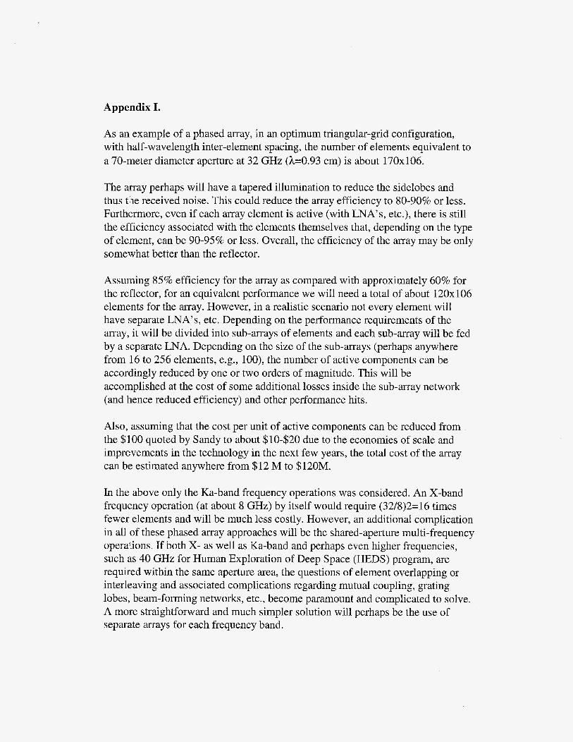
For a horizontal planar array, the peak is toward zenith. Such an array will be composed of small low gain elements (with a theoretical hemispherical coverage and a maximum gain of 3 dB) which will be spaced approximately half a wavelength apart to prevent grating lobes. This array can provide purely electronic scanning over the hemisphere, by the proper phasing of the individual elements to provide a uniform phase front in any desired direction as shown in Figure 2.
However, there will be a scan loss which will vary as the sine of the elevation angle (projected aperture in the boresight direction), namely, from 0 dB at zenith to as much as 3.0 dB at 30" and 7.6 dB at 10" elevation, as shown in Figure 1. The actual loss in elevation is even higher due to the additional element gain loss at lower elevations. We have also ignored the effects of the surface waves and diffraction from the edges of the finite array that prevent the radiation at the 0" elevation from going to zero according to the simple projected aperture theory.
In order to provide the same gain as a 70-meter reflector at 10" elevation, The aperture size of the array S, compared to that of the reflector, SO, need be approximately
S = SO / sin (10) = 5.8 SO , or, in terms of diameter, D = 2.4 DO = 168 m
The imposition of the coverage down to the 10" elevation may be a rather stringent requirement. Scanning down to such low elevations may cause many problems in the performance of the array such as blind spots, surface waves, etc. A better solution would either to reduce the scan angel. For example, if scanning only down to the 30" is set as an acceptable requirement, then the array size will
be only double that of the reflector, or a diameter of about 99 meters. Notice that this or a variation of it can be a viable option, since the array can still operate below the 30" elevation but with a lower gain (down by 4.6 dB at 10"). The array can be used for high data reception at or above the 30" elevation and with a reduced capacity but still acceptable performance below that elevation. A somewhat more detailed analysis of such a planar array in provided in Appendix I.
4.2. Hybrid mechanically/electronically steered array
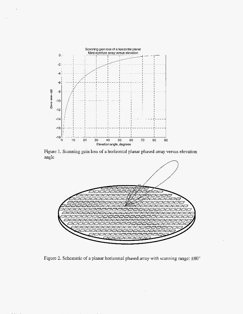
An alternative would be the use of a planar array pointed at 50" elevation angle (the array plane at a 40" angle from the ground) as shown in Figure 3. This array can provide coverage from 10" to 90" elevation angles with a maximum loss of only 1.16 dB for a maximum scan from peak to f40". Or, to provide the same gain as the reflector at 10 elevation will require the array area to be
S = SO / sin (50) = 1.3 SO , or, in terms of diameter, D = 1.15DO=80m
In this arrangement the electronic scanning is only in one dimension, namely elevation. The azimuth coverage will then be provided by mechanical rotation. Therefore the array in azimuth direction will not require phase shifters at the element or small sub-array of elements, but perhaps in each row only two large linear sub-arrays will be required with a phase shift between them to provide vernier electronic beam steering if needed. Also the beam-forming loss in each row can be reduced by the use of serial feeding arrangements as opposed to corporate feeding. All in all such an arrangement will require much smaller number of active components and electronics cost will be substantially lower, at the cost of mechanical azimuth steering and associated complexity and cost.
4.3. Multiple-face phased arrays
Another solution without any mechanical steering is the pyramidal arrangement of several planar phased array faces [ 1,2].
For example, Figure 4 shows a four-face array. Each face makes a 45 angle with the ground and needs to electronically scan to +45" from normal to provide full hemispherical coverage. This arrangement requires four planar faces each with
S = SO / sin (45) = 1.41 SO, or, in terms of diameter, D = 1.19 DO = 83 m
in order to provide the same gain as the reflector at 10" elevation. Or, alternatively, each face can be the same size as the reflector but with a scan loss of about 1.5 dB at the edge of its coverage.
Figure 5 shows a seven-face array. Top face is planar and each side face makes a 60 angle with the ground and needs to electronically scan to +30° from normal to provide full hemispherical coverage. This arrangement requires seven planar faces each with
S = SO / sin (60) = 1.155 SO, or, in terms of diameter, D = 1.075 DO = 75 m,
in order to provide the same gain as the reflector at 10" elevation. Or, alternatively, each face can be the same size as the reflector but with a scan loss of about 0.6 dB at the edge of its coverage.
In such multi-face arrays, only one of the faces need be operational at any given time and the face is switched as required. However, an added advantage is that more than one array can be operating simultaneously for communication with different spacecrafts, etc., thus providing a multiple beam coverage.
4.4 Phased-array fed lens antenna (dome antenna)
The dome antenna is another solution for providing hemispherical scan coverage with strictly electronic scanning. This antenna as shown in Figure 6, consists of a single planar phased array and a passive hemispherical microwave lens[3,4]. The planar array is horizontal. However, it scans only to a small angle, for example 30" from boresight). However, in radiating through the passive hemispherical dome lens which is composed of receive and transmit antenna elements, the wavefront is tilted to provide scanning down to a much lower elevation angle. Although this arrangement has some merit, the losses associated with the passive lens, and the quality of the wavefront transformation are rather problematic and make this option not a very viable one. It is possible to make the lens active by introducing T/R modules between the transmit and receive elements of the lens but then the cost and complications could become problematic.
4.5 Geodesic sphere phased array antenna
In yet another variation on the phased array concept, the array elements can be arranged on a spherical surface as shown in Figure 7. In the array, each triangular subarray panel constitutes a module. In each module antenna elements themselves

are arranged in a triangular grid [ 5 ] . The beam scanning is provided by a combination of switching the appropriate modules on or off, and by providing phase shift in elements of each module. This conecept is at an exploratory stage and further work is needed to flesh out the details and make it a viable alternative.
4.6 Phased array of mechanically steered reflectors
As already mentioned this array is composed of high gain directional elements which are themselves mechanically scanned toward the desired direction in addition to the proper phasing among the elements. Naturally this array does not provide the beam agility of a fully electronically steered array and is in that sense similar to a single mechanically steered array, although, the smaller reflector elements can be steered substantially faster than a very large reflector. In essence, this arrangement is a compromise between the phased array and the reflector concepts, combining many of the advantages and disadvantages of the two systems. The array element spacing must be such that there is no blockage between individual reflectors. However the total effective area of the aperture remains constant and equal to the sum of the aperture area of the individual elements. As a guide to the number and arrangement of such a scheme we provide the following. Total number of reflectors with a given diameter, D, equivalent to a single aperture reflector diameter Do = 70m, is
These reflectors can be compactly arranged in a triangular grid configuration. The minimum spacing between adjacent elements should be greater than
s = t D f sin(a>,
in which, a, is the minimum elevation angle and t factor is a number between 1.1 to 1.2 to account for diffraction effects. As shown in Figure 8, the total number of elements N, is arranged in a regular grid circumscribed within a circle of diameter S. The values of N and S are related to the number of elements along the diameter of this circle, n, by
N=(3 n2 + 1)/4, n=1,3,5, ...
S = (n-1) s + D, or
S / D = t { [(4(Do/D)2-1)/3]1/2 -l}/sin(a) +I
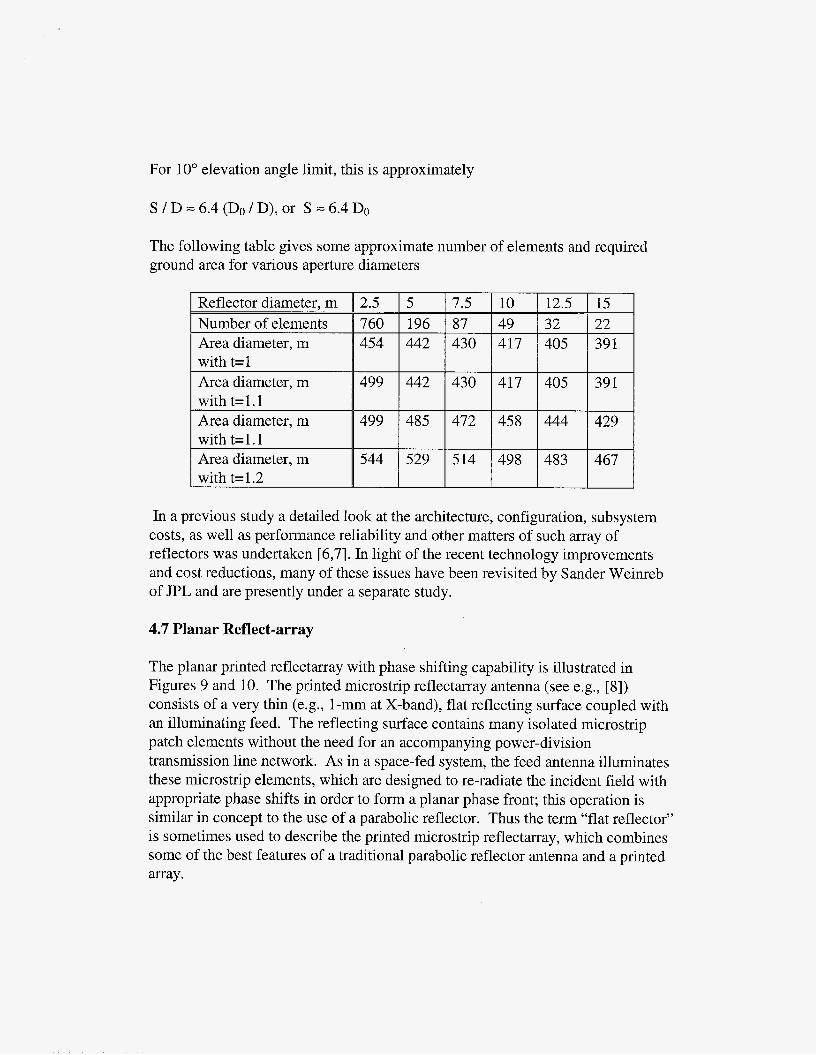
For 10” elevation angle limit, this is approximately
S / D = 6.4 (Do / D), or S = 6.4 Do
The following table gives some approximate number of elements and required ground area for various aperture diameters
15 22 39 1
39 1
429
467
In a previous study a detailed look at the architecture, configuration, subsystem costs, as well as performance reliability and other matters of such array of reflectors was undertaken [6,7]. In light of the recent technology improvements and cost reductions, many of these issues have been revisited by Sander Weinreb of JPL and are presently under a separate study.
4.7 Planar Reflect-array
The planar printed reflectarray with phase shifting capability is illustrated in Figures 9 and 10. The printed microstrip reflectarray antenna (see e.g., [8]) consists of a very thin (e.g., l-mm at X-band), flat reflecting surface coupled with an illuminating feed. The reflecting surface contains many isolated microstrip patch elements without the need for an accompanying power-division transmission line network. As in a space-fed system, the feed antenna illuminates these microstrip elements, which are designed to re-radiate the incident field with appropriate phase shifts in order to form a planar phase front; this operation is similar in concept to the use of a parabolic reflector. Thus the term “flat reflector” is sometimes used to describe the printed microstrip reflectarray, which combines some of the best features of a traditional parabolic reflector antenna and a printed array.

Similar to a parabolic reflector, a reflectarray can achieve relatively high efficiency (e.g., > 50%) with very large apertures since it does not require a transmission-line type power dividedcombiner as in the case of a conventional array, but does it spatially, and therefore incurs very little circuit insertion loss. Qn the other hand, the mainlobe of a reflectarray can be scanned quickly to relatively large angles (e.g., > 50") from its broadside direction just as an array antenna can, thereby achieving remarkable beam agility. As a benchmark, a circular 100-meter reflectarray would require 24 million and 350 million elements at X- and Ka-band respectively.
There are several methods for reflectarray elements to achieve the desired planar phase front. The first uses identical microstrip patches with different length phase delay lines attached so that they can compensate for the unequal phase delays due to the differing path lengths from the illuminating feed. Low-loss electronic phase shiftess employing micro-electro-mechanical switches (MEMS) can be inserted into these phase-delay lines to achieve electronic beam scanning. Since the antenna contains a very large number of elements, 2- or 3-bit phase shifters with low insertion loss are sufficient to achieve good overall beam scan resolution. The parallel-fed reflection-type phase shifters generally yield lower insertion loss than the conventional series-fed transmission-type phase shifters. The second method, which only works with circular polarization, employs identical circularly polarized elements with different angular rotations to compensate for the feed path length differences. Micro-machined motors can be placed underneath each patch to mechanically rotate the element and effect fast beam scanning. With this approach, there is nearly no insertion loss associated with the elements and beam- scanning speeds of the order of milliseconds can be readily achieved.
By using either the electronic phase shifters or the miniature motors, the complicated beamforming network and high-cost transmitkeceive (T/R) modules of a conventional phased array with millions of elements will be avoided.
A major drawback of the reflect-array is its narrow bandwidth behavior, which is directly attributable to the array element spacing and the phase delay lines. A given combination of array element spacing and phase delay lines will achieve peak performance only at a single frequency band. Multiple frequency bands could be achieved by using multiple vertically stacked patches, however this would increase the system complexity.
5. Digital beam-forming and other advanced technologies
Some of the more recent and novel technologies include optical beam-forming, digital beam-forming, which contribute significantly to viability of a fully electronically steered arrays. In a fully digitized system, there is no need for any phase shifters, the received signal is amplified and down converted either to an intermediate frequency or to the baseband, digitally sampled and then combined with all the other signals in a digital processing center. This provides total freedom in manipulating the signals and implementing any number of single or multiple bema-forming arrangements.
The complication is, however, in real time processing, particularly of broadband signal. Nonetheless, it is expected that by ever-increasing speed of digital computers and novel parallel processing techniques, such a scheme could become feasible in the next few years. There are a number of technology advances in the phased array area explored and implemented by DOD and the communications industry in recent years [9]. These issues need to be explored in some detail and more realistic cost figures should be obtained in order to be able to ascertain the feasibility of such systems for DSN applications in the next 10 to 20 years.
6. Summary and conclusions
In this paper we presented a review of the various phased array options for DSN applications. The following preliminary conclusions can be reached.
The technology for design and development of a large phased array is presently available. However, it has not reached the maturity and low cost levels needed to make it competitive with a reflector antenna system at the present time. We believe that in the next 10- 15 years the breakthroughs in mass production techniques at the components, modules and integrated circuit board level will be achieved that will make it an attractive option.
There are many advantages to a phased array system as compared to the current 70m DSN antenna network. These include, high beam agility, multi-beam multi- target applications, high reliability and easy maintainability. The disadvantages include much higher cost at the present, complexity of multi-frequency operations, inflexibility in adding new frequencies, and lower gain at lower elevations for a flat horizontal array.
The technology risks and the cost drivers include, primarily, the T/R modules and the beam-forming network architecture and implementation.

We propose that, as a proof of concept demonstration, a small scalable flat panel array be built and tested, in order to prove the maturity of the concept and to work out the potential problems at the T/R module and the beam-forming levels, for achieving a DSN-level performance. This could be a Im-square array at WKa bands. This panel could become an element of a much bigger array composed of such modular elements. The architecture of the connectivity and integration of this panel into a larger system would also be part of the proposed work.
7. Acknowledgements
The research described in this paper was carried out by the Jet Propulsion Laboratory, California Institute of Technology, under a contract with the National Aeronautics and Space Administration. The authors would like to acknowledge the efforts of Ed Burns, Jim Costrell, Barry Geldzahler, Paul Hertz, John Huang, Bany Levitt, Jeff Osman, Tim Pham, Sanders Weinreb, Christoper Yung, William Imbriale and others in the various activities leading to the preparation of this manuscript.

8. References
[ 11 6. H. Knittel, “Choosing the Number of Faces of a Phased-Array Antenna for Hemispherical Scan Coverage,” EEE Trans. Ant. Propagat., Vol. 13, No. 6, pp. 87 8-8 82, November 1 965.
[2] J.L. Kmentzo, “An Analytical Approach to the Coverage of a Hemisphere by N Planar Phased Arrays,” IEEE Trans. Ant. Propagat., Vol. 15, No. 3, pp. 367- 371, May 1967.
[3] J.J. Stangel and P.A. Valentine, “Phased Array Fed Lens Antenna,” US Patent No. 3,755,815, August 28, 1973.
[4] P. M. Liebman, et al, “Dome Radar - A New Phased Array System,” Digest of IEEE International Radar Conference, Washington, D.C., April 1975.
[5] P. K. Bondyopadhyay, “The Cellular Scanning Concept and its applications,’’ Proceedings of 2000 Antenna Applications Conference, Allerton Park, Il, pp. 134- 141, Sep. 2000.
[6] V. Jamnejad, “Cost and Reliability Study for Large Array of Small Reflector Antennas for Deep Space Network Applications,” 1993 IEEE Aerospace Applications conference Digest, pp. 121-132, Ja. 31, Feb. 5, 1993.
[7] G. Resch, et al, “Synthesis of a Large Communications Aperture Using Small Antennas,” JPL Publication 94-15, July 1, 1994.
[8] J. Huang and R. J. Pogorzelski, “A Ka-band microstrip reflectarray with elements having variable rotation angles”, IEEE Transactions on Antennas and Propagation, Vol. 46, May 1998, pp. 650-656.
[9] M. 6. Parent, et al, “Wideband Digital Subarray Beamforming Using True Time Delay Steering at the element level,” Proceedings of 2000 Antenna Applications Conference, Allerton Park, Il, pp. 134- 14 1, Sep. 2000.
Appendix I.
As an example of a phased array, in an optimum triangular-grid configuration, with half-wavelength inter-element spacing, the number of elements equivalent to a 70-meter diameter aperture at 32 GHz (h=0.93 cm) is about 170x106.
The array perhaps will have a tapered illumination to reduce the sidelobes and thus the received noise. This could reduce the array efficiency to 80-90% or less. Furthermore, even if each array element is active (with LNA’s, etc.), there is still the efficiency associated with the elements themselves that, depending on the type of element, can be 90-95% or less. Overall, the efficiency of the array may be only somewhat better than the reflector.
Assuming 85% efficiency for the array as compared with approximately 60% for the reflector, for an equivalent performance we will need a total of about 120x106 elements for the array. However, in a realistic scenario not every element will have separate LNA’s, etc. Depending on the performance requirements of the array, it will be divided into sub-arrays of elements and each sub-array will be fed by a separate LNA. Depending on the size of the sub-arrays (perhaps anywhere from 16 to 256 elements, e.g., loo), the number of active components can be accordingly reduced by one or two orders of magnitude. This will be accomplished at the cost of some additional losses inside the sub-array network (and hence reduced efficiency) and other performance hits.
Also, assuming that the cost per unit of active components can be reduced from the $100 quoted by Sandy to about $10-$20 due to the economies of scale and improvements in the technology in the next few years, the total cost of the array can be estimated anywhere from $12 M to $120M.
In the above only the Ka-band frequency operations was considered. An X-band frequency operation (at about 8 GHz) by itself would require (32/8)2=16 times fewer elements and will be much less costly. However, an additional complication in all of these phased array approaches will be the shared-aperture multi-frequency operations. If both X- as well as Ka-band and perhaps even higher frequencies, such as 40 GHz for Human Exploration of Deep Space (HEDS) program, are required within the same aperture area, the questions of element overlapping or interleaving and associated complications regarding mutual coupling, grating lobes, beam-forming networks, etc., become paramount and complicated to solve. A more straightforward and much simpler solution will perhaps be the use of separate arrays for each frequency band.
J -
1
80
- - - ---I 1 i 90
Elevation angle, degrees
Figure 1. Scanning gain loss of a horizontal planar phased array versus elevation angle
Figure 2. Schematic of a planar horizontal phased array with scanning range: f80"
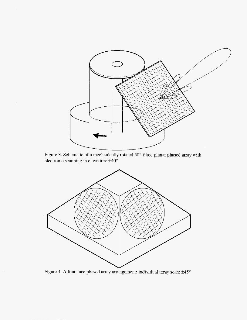
Figure 3. Schematic of a mechanically rotated 50"-tilted planar phased array with electronic scanning in elevation: rt40".
Figure 4. A four-face phased array arrangement: individual array scan: f45"
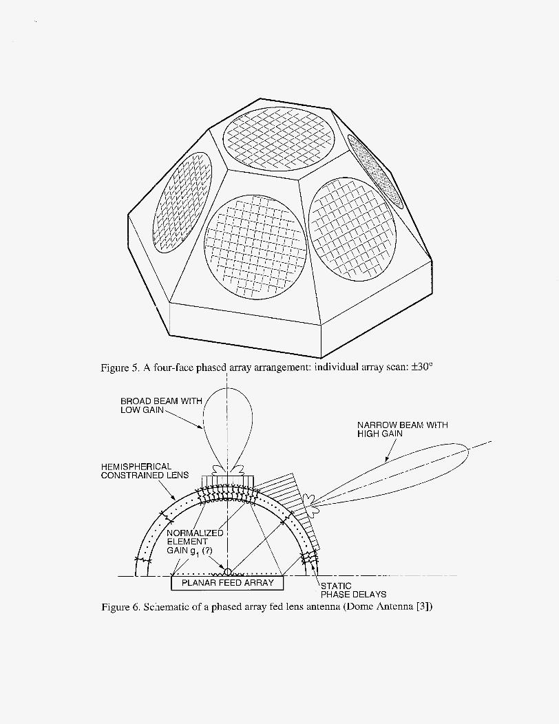
Figure 5. A four-face phased array arrangement: individual array scan: f30" I I
NARROW BEAM WITH HIGH GAIN
/-
HEM IS PH ERI CAL
PHASE DELAYS Figure 6. Schematic of a phased array fed lens antenna (Dome Antenna [3] )
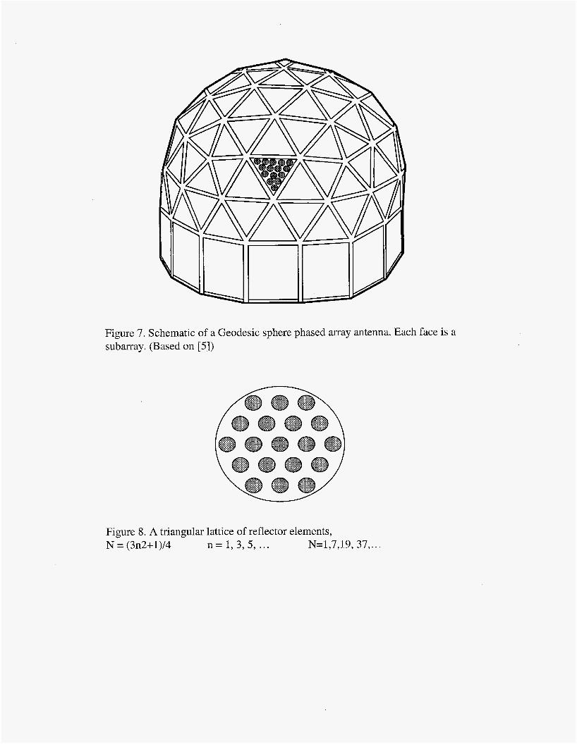
Figure 7. Schematic of a Geodesic sphere phased array antenna. Each face is a subarray. (Based on [ 5 ] )
Figure 8. A triangular lattice of reflector elements, N = (3n2+1)/4 n = 1 , 3 , 5 , ... N=1,7,19, 37 ,...
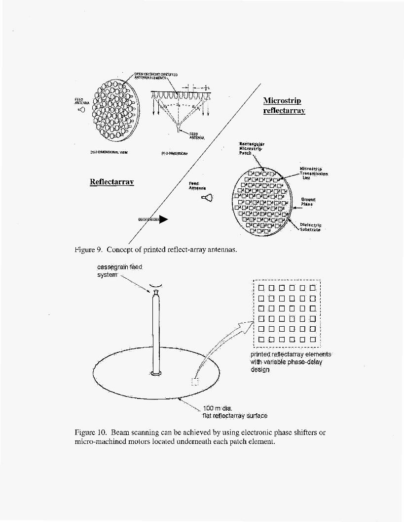
Figure 9. Concept of printed reflect-array antennas.
S
design 1
rfa
Figure 10. Beam scanning can be achieved by using electronic phase shifters or micro-machined motors located underneath each patch element.