Embed Size (px)
Citation preview

Lehigh UniversityLehigh Preserve
Fritz Laboratory Reports Civil and Environmental Engineering
1937
A study of structural sections subjected to torsion,Journal of Faculty Sciences, University of Istanbul,Jan. 1937I. Lyse
Follow this and additional works at: http://preserve.lehigh.edu/engr-civil-environmental-fritz-lab-reports
This Technical Report is brought to you for free and open access by the Civil and Environmental Engineering at Lehigh Preserve. It has been acceptedfor inclusion in Fritz Laboratory Reports by an authorized administrator of Lehigh Preserve. For more information, please [email protected].
Recommended CitationLyse, I., "A study of structural sections subjected to torsion, Journal of Faculty Sciences, University of Istanbul, Jan. 1937" (1937). FritzLaboratory Reports. Paper 1156.http://preserve.lehigh.edu/engr-civil-environmental-fritz-lab-reports/1156
brought to you by COREView metadata, citation and similar papers at core.ac.uk
provided by Lehigh University: Lehigh Preserve

. -FRiTZ ENGi~1E£j{n~G LABORATORY,
'<._, . LEHIGH UNIVERSITY, '-," BETHLEHEM, PENNSYLVAI'iIA
A STUDY OF STRUCTURAL SECTIONS SUBJECTED TO TORSTON*;'
by Inge Lyse**
I*"l~
Ilof·7
The general relationship between angle of twist and
tor~ional moment in, a circular section is-given by: T = J.G.e,
where T is tor~ional moment, J is polar moment of inertia,
G fs shearing modulus of elasticity, and e is angle of twist.
For non,:"cir:cular sections we may similarly set: T = K.G.e,
where K represents the resistance of the section to tors'ional
deformation. TheK-value therefore, becomes the important item
for the determination of shearing stresses in structural shapes.
For a rectangular section Saint Venant developed the following
equation for the torsional rigidity:. 3K = b.!L _ 2v.n4
3
where: b = length of rectangular section
(1)
n = thickness or breadth of rectangular section
V = a constant depending on the ratio bn
For the ratio bin greater than 4 the value for'V = 0.10504. Con
sidering the soap fibrr analogy, the expression -2Vn4 represents
nend lOSS". For any differential length, dx, along the rectangu
lar' section the rigidity is:
*
**
- - - - - - _.- - - - - - - - - - - - - - - - - - - - - - - -A detailed description of an extensive investigation of thisproblem has been pUblished in a paper: STRUCTURAL BEAMSIN TORSION by lnge Lyse and Bruce G. Johnston, Proceedings,of the American Society of Civil Engineers, April 1935,'pp. 369... 508.
Research Assoc~ate Professor of ~ngineering MaterialsLehigh University, Bethlehem, Pennsylvania
(2)
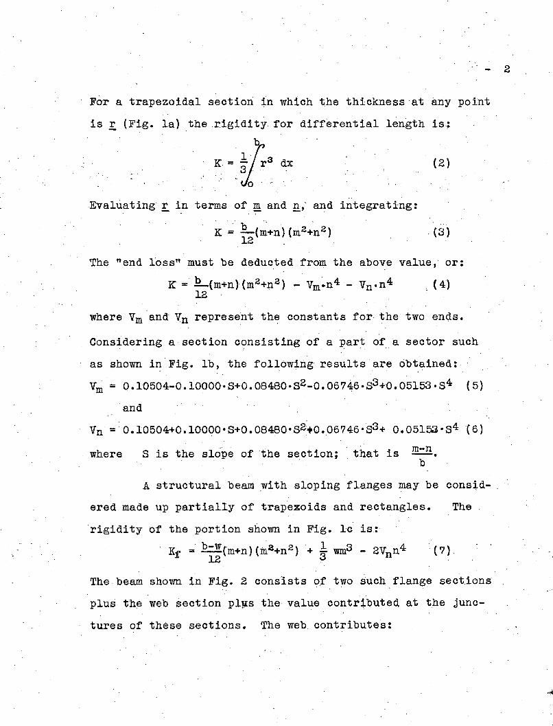
For a trapezoidal section in which the thickness 'at any point
is £ (Fig. la) the ,rigidity for diff~rential length is:
K ~ ~1:3 dxYo-,
2
,Evaluating r in terms of ~ and .!h and integrating:
, ~. ~ JL(~+n') (m2~n2)12 ,
(3 )
The "end loss" must be deducted from the above value, or:
K = !!....(m+n)(m2 +n2 ) ... Vm~n4 - Vn .n4 c (4)12 .
where Vm and' Vn represeht the constants for· the two'ends.
Cons~dering a section eonsisting of a part of 8 sector such
as shown in Fig. Ib, the fol~owingresultsareobtained:
Vm = 0.10504-0.10000.8+0.08480.82..0.06746.83+0.05153.84 (5)
and
Vn =: 0.10504+0.10000.8+0.08480.82'+0.06746.'83+ 0.05153.84 (6)
where 8 is the slope of the section; that is m-n-.b
A structural beam with sloping flanges may be cons~d- ,
ered made up partially of trapezoids and rectangles. The
rigidity of the portion shown in
K =' b-W('m+n) (m2 +n 2 )f. 12
Fig. lc is:
+ ~ wm3 - 2Vnn4 (7)
The beam shown in Fig. 2 consists o,f two such flange sect.ions
plus the web section pl!ls the value contributed at the junc
tures of these sections. The web contributes:

- <3
(8)
-,
The rigid,ity contributed by the juncture has generally been
considered proportional tb the fdurth power of the largest
inscribed-circle; that is:
(9)
where: D = diameter of inscribed 'circle, and a. = a factor
depending upon, the ratios .!! and r. The valUes of a. were de-m m
, ,
termined experimentally by soap -film tests which-gave the
following results for parallel flange sides:
a. = 0.094 + 0.070!,"m
(10)
For flanges ,with sloping sides the following results-were
obtained. For slope ofl on 20: , a. = 0.066+0.02~: +0.072i
for slope of 1 on 50: a. ~ 0.084 + 0.007w + 0.071rm m
SUinmari'zing the various elements we obtain-for. par-
allel-sided flanges:. -2 ' I' K = _bn3 +-(d-2n) .w3+ ,2a.D4 .. 0.42016n4 (11)3 ,3 -- ,
and for sloping flange sections:
K = b-W(m+n) (m2 +n 2 )+I(d-2m) .w3+2a.D-4Vn .n4 (12)6 3- - ,
The diameter of the inscribed circle is found by the following
formula for the parallel-sided flange sections~
D =--------2r"", n
and ,for sloping flange sections:,
(13)

(14)(r.8(~1 +1' -1- !L)+z\ 2+w(r+ !!)
D =82 . 2r j 4.
r.S. (VI +1 ..;. 1 - -!!). + r + z. S2. .' 2r
where z= the maximum flange depth shown in Fig. 2. The shear-
4
'. (15) .
ing stress is a function of the thickn'essof mater'ial ~nd the.:
following',equations were found to give fairly accurate maximum ... ,
shearing stress in ,the flange and in the ,web of structure:lbeam: '
For parallel-sided flange:.... _T(n+O.3r}:!'f - - K - .
For sloping flange sections:
= !Jm+O.3r)K
and for the web:
. _. 'r.{w+O.3rt ..'t"w - ,. K
(16)
(17)
For structural sections·restrained at the ends we, have
the following conditions. Referring' to Fig. 3 the torsional
moment is readily seen to be:
in which
T . = KG ~ = 2K.G.~11 dx. h dx
(18)
(19) .
where: .K is the torsional constant for the section, and G is
the modulus of shear•. If !l. denotes the larger m~ment of in,2
ertia of one flange, we have:
Ely .d3 yQ. = _.
2 dx3(20)

Thus:
5
(21)
Setting
a = h ,jElY.2 KG
and reducing t we have:
'd3 y dv .hT' "a 2 _.:=Jl..+-·-=.O
'dx3 dx, 2K·G(22)
The diff'erential equation (22:) has the gener~l solution:" ,
y =A ,sinh 2£ +B cosh 2£,+ C + Yl (23)a . 'a '
where: ' A, 'E, and C are determined' by t~e border conditions
'and Yl is the solution which satisfies equation' (22).
For a section fixed at both ends equation (~3) be-'
comes:
or for x = IJ.·. --t:...
Y = T·h·a (~- 2 tanh .L)2 K·Q a" .' 2a
(25) ,
The bending moment in each flange is:
Ely d2 y ,T.a sinh (L _X)-, 2a a
M = '2' .' dx2 = h cosh' L (26)
2a
the shear:
, (27)

5
(28)I h·ly
Mb· T•a •b sinh' (~ -!')___ . a a
cosh·1·. 2a
-=I
=~=
and the +ongftudinal stresses at the outer fibres of· the
flanges:
The angular twist at the center of the' section is
given by:
. (29)
. d\lr __ 2. dvec = ai"h ~. By use of e-quation (24) we obtatn:
cosh ~ - 1.T 2a
=KG cosh :::e:
2a
Due to the shortening of 'the beam during twisting. a correct
ion factor must be applied when cros~-sections are restrained
from warping•. Professor Timoshenko* has shown' that a correct
ion of: 1 + 2.95 1.: should be used, that is:
cosh ~ 1 .. b 2Q. :: L .2a (1 2 95) (30). c KG J)" + .• .~2 ".
cosh ~"
or the torsion con~tant for this case is:
t cosh ~t .i ~= T -K . .2a _..;...._--.-e•.G- cosh -1 1+2.95ba
" 2a .' ~
(31) .
The theoretical study was substantiated by experiments on full
sized structural sections. T~e loading rig used for these test~"
is shown inFig.4• .An illustration of the observed stress dis
tribution in "free-ended sections is sho"wn in Fig.5, 'and in fUlly
restrained s~ctions in Fig.5. Fig.? shows the~relationship ~e
tween computed arid observed stiffnessesas well as Yl~eld points
of fixed-ended beams, and Fig.8 indicates the agreement between
the computed and observed shearing stresses in" the beams.- - - - - - - - - ~ - - ~.- - - - - - - - - - - - - -* S. Timoshenko STRENGTH OF MATERIALs, :Vo1. 1

:cr JJro- b--Jlb) PART OF A SECTOR
1101 .+-~,,-~ b .. I
(e) SLOPING FLANGE SECTION~- q-'-~~
Fig. 1Sections With~loping Sides Fig. 2 - structural
Beam Sections
Fig. 3 Illustration or Twisting of Beam

Fig. 4 - Loading Arrangement for Twisting Beams

48
40
8
/'V
/
/1/ I
Yield Point~ Strain Lines onof Beam Fenter Line or FlangeI \Drop of Beam and
_§.J Strail Lines along lillet5
~: I _I~ 't'= 12000 Ib per sq in.by Formula
~ II ~'t'= 12000 lb per sq in.by Tensometers
''''V (a) i-DIAGRAM
~ ~
~~~~
fj,-E.I" 10
<n
MaterialYield Point
Stress Distributionat Beam Yield Point
(b) SHEARINGSTRESS
DISTRIBUTIONON SURFACE
OF FLANGE ANDWEB
0.002 0.004 0.006Unit Twist in Radians
0.008 0.010
7
Fig. 5 Free-Ended Tqrsion Test
~5"1I I
I
I
Shear Tensometers
(el TOP VIEW OF FLANGE
Stiffeners
Tensometersfor~DirectStress
Idl DIRECT STRESS IN OUTER FIBERS OF FLANGE ATYIELD POINT OF THE BEAM .
5"
40f----f:c-----
rI
40
__________ 6·0··c.- -.,
I
~ I:Jl 20 f----f---~---':-"...=-
~.~ Tension in Top
~ ~ or-__O_"t_er_F_ib_er -=::::,-.."""';:- +~ .~~
V5=~ 0 20
~
0.0050.0040.002 0.003Unit Twist in Radians
O.OOt
0
,/----I~
IF Yield Pointof Beam
).7 00p.>~. .-"It" I . (b) SHEARING STRESS
AT SECTION a-a AT 1
o . THE YIELD POINTI) I ~"''' " '"' .".(a) f-DIAGRAM
I
12
~c,If. 80
~"0~c,
.,~ 60c
cE!1
"g "40'@0=
100
oo
Fig. ·6 Fixed-Ended Torsion Test

o \o \
\
IO~\-'---'--1-'-,,/---,----I~,-----,\ I", RELATION BETWEEN LENGTH AND STIFFNESS
\\\-\---- -\\\
o \
" 6 -- \-- ---c----!I-----l------I------j-----i
\\\ Theoretical'r/
~ 4 f-'------'-\~ ----~-I-----~I---~__j
! , "f\('"'' ! I2 __1~_'~11-1--+----14 __ _ __l J~~==±=---~---- _I I Comp",d FT'End'd SI.Hnm I ' '
I I I I.</., RELATION BETWEEN LENGTH AND YIELD,POINT STRENGTH
I\ I6~\-\ \--I--f---j
~Th'O"'"''To,o" 10' "m•• =38900 I. po< so 'n.
, \ \,,~",.',-nlO-'8.-.ms,-.YT--+est---1----+-------j
8 \ ~Theoretical Torque fOf'Tm;u =21 800 lb per sq tn.~ . I '1" '........... __ F,ee,End.d Y",'d-'~~=2' 8001. POI So ,n,
------~--::::-:::,,--i----,L--t---=--=--=--=.::.r-=.-====t-=:==4 L-------:'IO=-----2:':O--,----:3'::-0------:40;;-----;';SO=----~60
length 01 Beam Inches
Fig.' " - Effeot ,of End Fixity OnTorsional Rigidity of Beams
,J
.. ~.

10 r----r--j---,--,-----,-----,----,------.------,
10
/
"c:::;
3·IN. I·BEAM 3B.96 IN. LONG
1----I~-I-___=_____",¥---+-----1
o 2Distance from Center Line in Inches
("i TEST T-IO
-----..- --'--Ic----I-·~.-I----I
4
02--\------------Ii» TEST T-B 3·IN. I-BEAM IB.10 IN~ LONG
~---
\ Jf\\
----------"
/
c k!/'~
:::;
" Theoretical
"c
---~~ --- .6
V/.....~ ~~ _..;:;i
0
------------I---
10 8 6 4 2
\\\
B' -\~ ----
\\\\
6 - -\--I----I----I----~---I----j----I\
. 2
~
" 0~-_____t5~-~--{------,;----+----:\:---:;-~-~20 15 . 10 5 0 5 10 - 15 20
Distance from Cenler line in Inches
:10o...
'"• c, Ir
;;
". c,o
Q.
Fig. 8 _ Relation Between Computed and ObservedShearing stresses in Fixed-Ended Beams


![Calcul des caractéristiques d’une poutre de sectio[] · 2.3.3 Exemple ... 3.4 Constante de torsion des sections circulaire et rectangulaire.....19 3.5 Le rayon de torsion efficace](https://img.pdfslide.net/doc/110x75/5b3201687f8b9aae458b92c8/calcul-des-caracteristiques-dune-poutre-de-sectio-233-exemple-34.jpg)