Embed Size (px)
Citation preview
A study on the causes of troubles in shield tunneling site with numerical analysis
1B.K. Rho, 2S.Y. Choo, 2M.K. Song Korea Rail Network Authority, Daejeon, Korea1; Danwoo E&C Co., Ltd., Sungnam, Korea2
Abstract
Shield TBM tunneling method along with other mechanized method is one of the preferred ways to make tunnel, especially for long tunnel with unfavorable ground condition. Shield method is well known to be effective and safe to make tunnel on shallow and poor ground condition. However, occasional troubles or accidents occurred because of mechanical or geological reasons, such as improper selection of equipment, malfunction, encounter with unexpected geologic layers and large infiltration of ground water. Shield tunneling method constitutes open-end and closed-end type. Open-end type shield is used when the geological condition is fairly good and has enough stand-up time for at least one cycle. Closed-end type shield is used when the geological condition is so unfavorable that tunnel face becomes unstable without instant application of support pressure. Closed-end type shield constitutes earth-pressure-balanced shield and slurry shield. Balance between acting earth pressure and resisting support pressure is important for the closed-end type. To prevent the undesirable event, not only maintenance of equipment and detailed geological investigation but also application of proper support pressure on the tunnel face is required. Both analytical solution and numerical simulation is combined to predict proper support pressure. An analytical solution, developed by Anagnostou and Kovari(1996), is used for calculation of support pressure of EPB shield tunnel. For numerical solution, finite difference method (FLAC) and distinctive element method (PFC) is used. The former is used for the ground reaction behavior of rock mass; the latter is used for large displacement behavior of ground when the ground support varies. With simple model test case for water saturated ground, analytic solution predicts that pressures 82 kPa and 66 kPa are necessary for non-cohesive and cohesive ground condition. For unsaturated ground, analytic solution predicts that pressures 46 kPa and 32 kPa are necessary for non-cohesive and cohesive ground condition. The results show consistency between analytic and numerical approaches, as latter show significant decline of displacement up to the predicted support pressure and minor decline is minute for more support pressure. With this study, systematic estimation methods of tunnel face stability using numerical and analytical solution is proposed and verified. This approach is expected to be easily adapted and to enhance the reliability of design and construction phase. Once the earth pressure is known, appropriate support pressure or stiffness can be applied for the excavation of shield tunnel.
Introduction
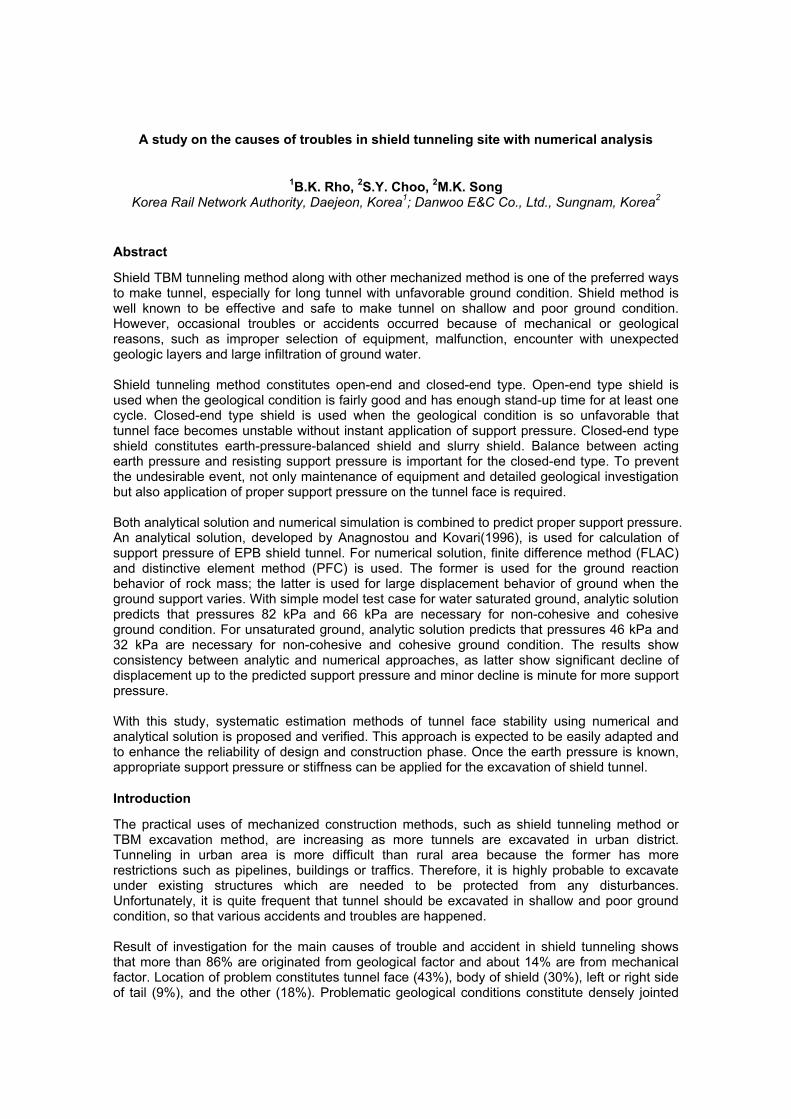
The practical uses of mechanized construction methods, such as shield tunneling method or TBM excavation method, are increasing as more tunnels are excavated in urban district. Tunneling in urban area is more difficult than rural area because the former has more restrictions such as pipelines, buildings or traffics. Therefore, it is highly probable to excavate under existing structures which are needed to be protected from any disturbances. Unfortunately, it is quite frequent that tunnel should be excavated in shallow and poor ground condition, so that various accidents and troubles are happened. Result of investigation for the main causes of trouble and accident in shield tunneling shows that more than 86% are originated from geological factor and about 14% are from mechanical factor. Location of problem constitutes tunnel face (43%), body of shield (30%), left or right side of tail (9%), and the other (18%). Problematic geological conditions constitute densely jointed
blocky rock (24%), fault (18%), loosened soil mass (13%), swelling rock mass (10%), and the other (35%). So, it is evident that most of problem occurred at tunnel face with poor ground condition. As a matter of fact, these geological and mechanical factors are combined to cause collapse or sliding at tunnel face, that is, failure of control for tunnel face support. In this study, we analyze a theoretical calculation method of tunnel face supporting pressure for safety of tunnel face. Moreover, behavior of rock mass around TBM excavated area is analyzed using numerical analysis under EPB shield TBM construction condition.
A main trouble factors
A trouble occurrence position Table 1: Trouble cases of shield TBM
Calculation method of tunnel face supporting pressure in EPB shield TBM
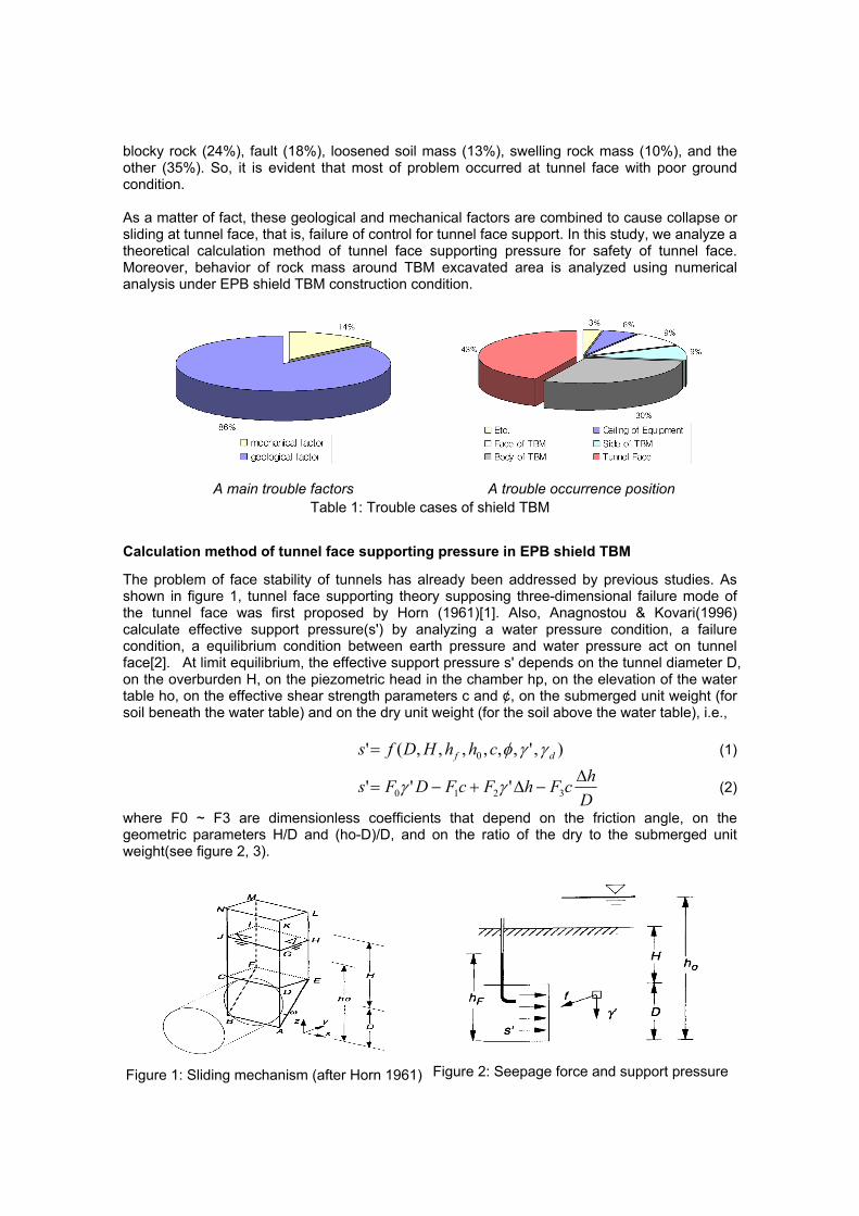
The problem of face stability of tunnels has already been addressed by previous studies. As shown in figure 1, tunnel face supporting theory supposing three-dimensional failure mode of the tunnel face was first proposed by Horn (1961)[1]. Also, Anagnostou & Kovari(1996) calculate effective support pressure(s') by analyzing a water pressure condition, a failure condition, a equilibrium condition between earth pressure and water pressure act on tunnel face[2]. At limit equilibrium, the effective support pressure s' depends on the tunnel diameter D, on the overburden H, on the piezometric head in the chamber hp, on the elevation of the water table ho, on the effective shear strength parameters c and ¢, on the submerged unit weight (for soil beneath the water table) and on the dry unit weight (for the soil above the water table), i.e.,
),',,,,,,(' 0 df chhHDfs γγφ= (1)
DhcFhFcFDFs Δ
−Δ+−= 3210 ''' γγ (2)
where F0 ~ F3 are dimensionless coefficients that depend on the friction angle, on the geometric parameters H/D and (ho-D)/D, and on the ratio of the dry to the submerged unit weight(see figure 2, 3).
Figure 1: Sliding mechanism (after Horn 1961)
Figure 2: Seepage force and support pressure
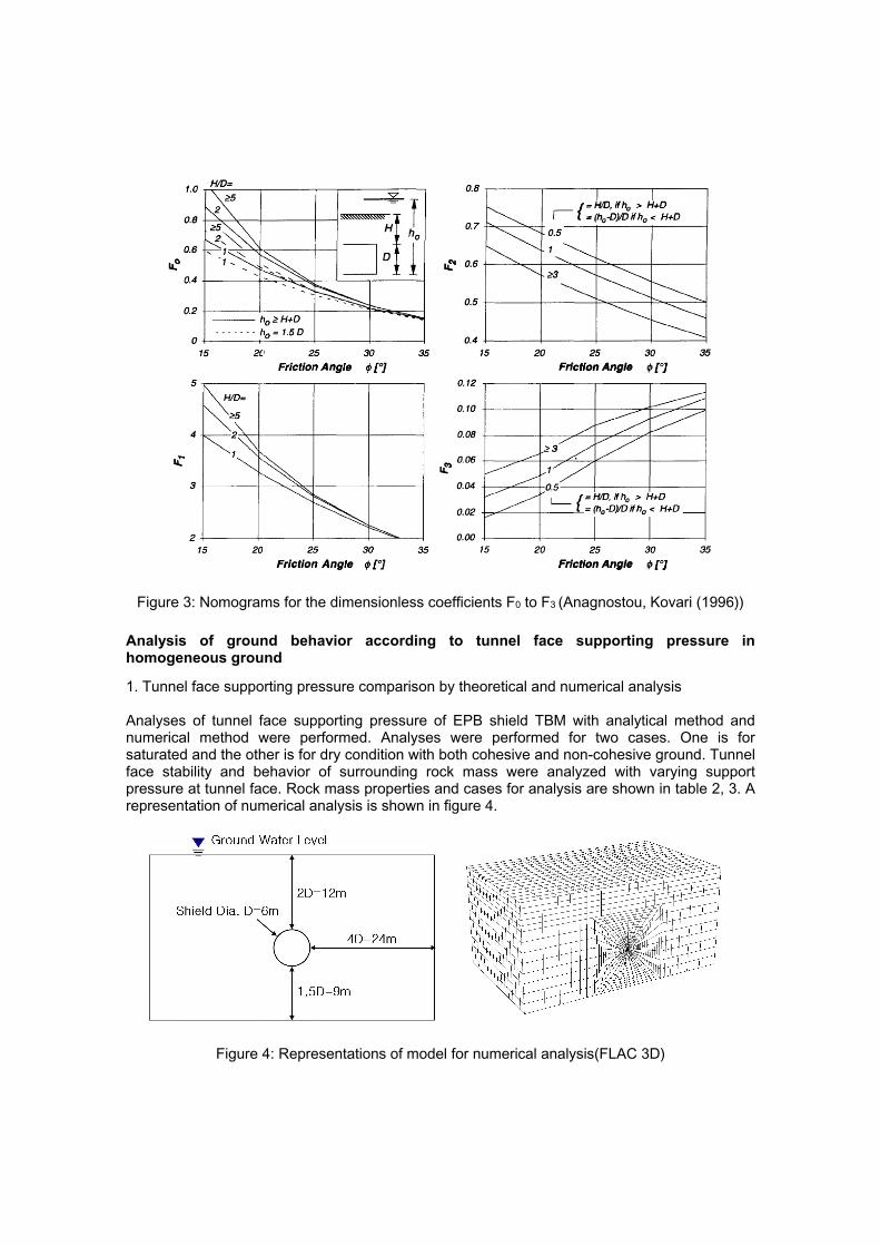
Figure 3: Nomograms for the dimensionless coefficients F0 to F3 (Anagnostou, Kovari (1996))
Analysis of ground behavior according to tunnel face supporting pressure in homogeneous ground
1. Tunnel face supporting pressure comparison by theoretical and numerical analysis Analyses of tunnel face supporting pressure of EPB shield TBM with analytical method and numerical method were performed. Analyses were performed for two cases. One is for saturated and the other is for dry condition with both cohesive and non-cohesive ground. Tunnel face stability and behavior of surrounding rock mass were analyzed with varying support pressure at tunnel face. Rock mass properties and cases for analysis are shown in table 2, 3. A representation of numerical analysis is shown in figure 4.
Figure 4: Representations of model for numerical analysis(FLAC 3D)
dry unit weight submerged unit weight elastic modulus cohesion friction angle
soil 20 kN/m3 12 kN/m3 15 MPa 0 kPa
25° 5 kPa
Table 2: ground properties used in numerical analysis
Groundwater No groundwater
CASE 1 CASE 2 CASE 3 CASE 4 D (shield diameter) 6m
H (soil depth) 12m(2D) ho
(groundwater level) 12m(2D, full level) -
c (cohesion) 0 kPa 5 kPa 0 kPa 5 kPa tunnel face
supporting pressure 0, 50, 100, 150, 200, 300 kPa 0, 20, 40, 60, 100, 150 kPa
Table 3: Analysis cases used in numerical analysis
2. Results of numerical analysis
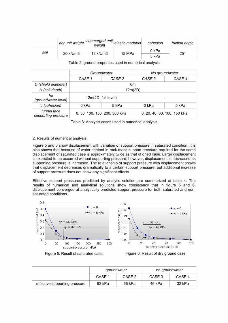
Figure 5 and 6 show displacement with variation of support pressure in saturated condition. It is also shown that because of water content in rock mass support pressure required for the same displacement of saturated case is approximately twice as that of dried case. Large displacement is expected to be occurred without supporting pressure; however, displacement is decreased as supporting pressure is increased. The relationship of support pressure with displacement shows that displacement decreases dramatically to a certain support pressure, but additional increase of support pressure does not show any significant effects. Effective support pressures predicted by analytic solution are summarized at table 4. The results of numerical and analytical solutions show consistency that in figure 5 and 6, displacement converged at analytically predicted support pressure for both saturated and non-saturated conditions.
Figure 5: Result of saturated case Figure 6: Result of dry ground case
groundwater no groundwater
CASE 1 CASE 2 CASE 3 CASE 4
effective supporting pressure 82 kPa 66 kPa 46 kPa 32 kPa
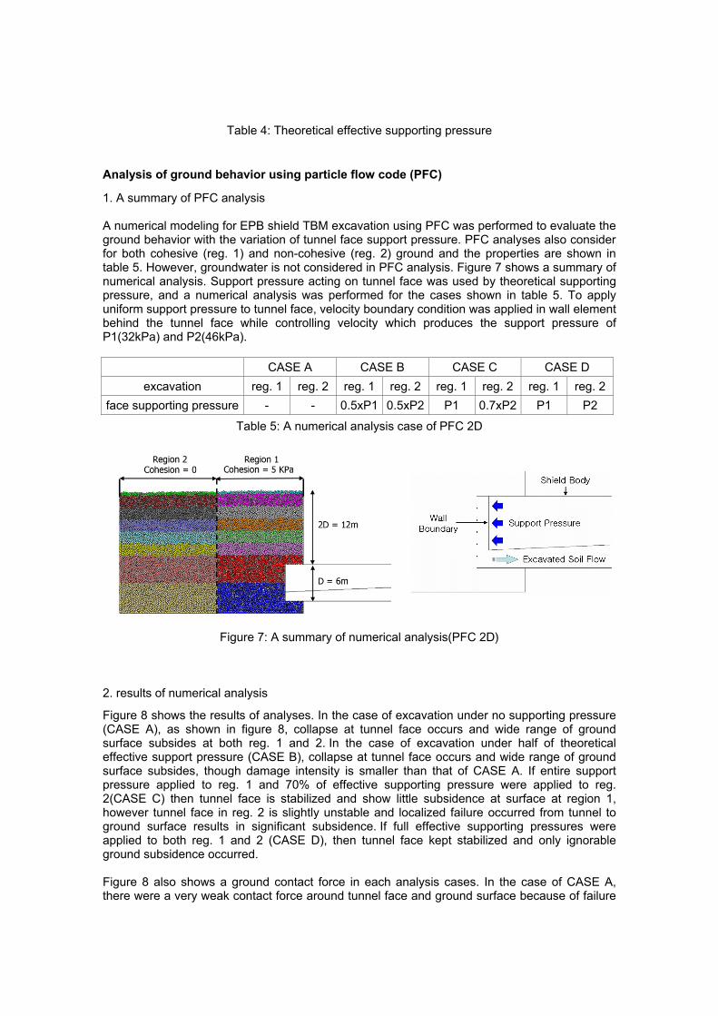
Table 4: Theoretical effective supporting pressure
Analysis of ground behavior using particle flow code (PFC)
1. A summary of PFC analysis A numerical modeling for EPB shield TBM excavation using PFC was performed to evaluate the ground behavior with the variation of tunnel face support pressure. PFC analyses also consider for both cohesive (reg. 1) and non-cohesive (reg. 2) ground and the properties are shown in table 5. However, groundwater is not considered in PFC analysis. Figure 7 shows a summary of numerical analysis. Support pressure acting on tunnel face was used by theoretical supporting pressure, and a numerical analysis was performed for the cases shown in table 5. To apply uniform support pressure to tunnel face, velocity boundary condition was applied in wall element behind the tunnel face while controlling velocity which produces the support pressure of P1(32kPa) and P2(46kPa).
CASE A CASE B CASE C CASE D excavation reg. 1 reg. 2 reg. 1 reg. 2 reg. 1 reg. 2 reg. 1 reg. 2
face supporting pressure - - 0.5xP1 0.5xP2 P1 0.7xP2 P1 P2
Table 5: A numerical analysis case of PFC 2D
Figure 7: A summary of numerical analysis(PFC 2D)
2. results of numerical analysis
Figure 8 shows the results of analyses. In the case of excavation under no supporting pressure (CASE A), as shown in figure 8, collapse at tunnel face occurs and wide range of ground surface subsides at both reg. 1 and 2. In the case of excavation under half of theoretical effective support pressure (CASE B), collapse at tunnel face occurs and wide range of ground surface subsides, though damage intensity is smaller than that of CASE A. If entire support pressure applied to reg. 1 and 70% of effective supporting pressure were applied to reg. 2(CASE C) then tunnel face is stabilized and show little subsidence at surface at region 1, however tunnel face in reg. 2 is slightly unstable and localized failure occurred from tunnel to ground surface results in significant subsidence. If full effective supporting pressures were applied to both reg. 1 and 2 (CASE D), then tunnel face kept stabilized and only ignorable ground subsidence occurred. Figure 8 also shows a ground contact force in each analysis cases. In the case of CASE A, there were a very weak contact force around tunnel face and ground surface because of failure
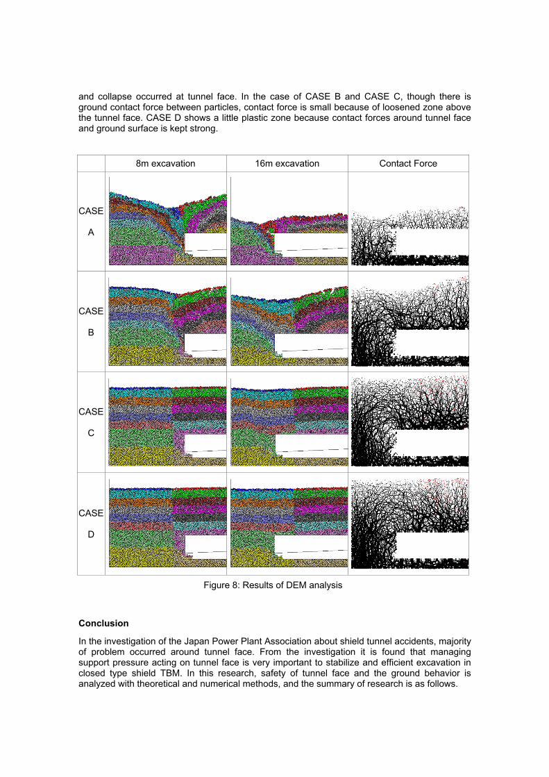
and collapse occurred at tunnel face. In the case of CASE B and CASE C, though there is ground contact force between particles, contact force is small because of loosened zone above the tunnel face. CASE D shows a little plastic zone because contact forces around tunnel face and ground surface is kept strong.
8m excavation 16m excavation Contact Force
CASE A
CASE B
CASE C
CASE D
Figure 8: Results of DEM analysis
Conclusion
In the investigation of the Japan Power Plant Association about shield tunnel accidents, majority of problem occurred around tunnel face. From the investigation it is found that managing support pressure acting on tunnel face is very important to stabilize and efficient excavation in closed type shield TBM. In this research, safety of tunnel face and the ground behavior is analyzed with theoretical and numerical methods, and the summary of research is as follows.
(1) Results of numerical analysis of ground behavior for various support pressure, while considering hydro-mechanical coupling with groundwater, shows that significant decrease of displacement as to a certain support pressure. However, for higher than certain support pressure, additional displacement decrease is minor. Moreover, results of numerical method and analytical method are consistent, that at the pressure predicted by analytical method, displacement is controlled and tunnel face also stabilized. (2) For the realistic behavior of rock mass excavated by EPB shield machine, PFC analyses were performed. Results of PFC analyses show that support pressure is so critical that failure and collapse are predicted for every case which is without support pressure. For the case of 70% of effective support pressure applied, even though tunnel face seems to be stable but ground subsidence is occurred due to loosened zone in rock mass ahead of tunnel face. For the case that full effective support pressure is applied, not only tunnel face is stable, but also subsidence of ground surface is minor, as support pressure prevents the loosening of rock mass.
References
[1] M. Horn. “Alagutak homlokbiztositására ható vizszintes földnyomásvizsgálat nehány eredménye. ” Az országos melyepitóipari konferencia eloádásai, Közlekdedési Dokumentaciós Vállalat, Budapest(in Hungarian), (1961).
[2] G.Anagnostou and K.Kovari, “Face Stability Conditions With Earth-Pressure-Balanced Shields", Tunnelling and Underground Technology, Vol.11, No.2, pp.165-173, (1996)
[3] G.Anagnostou and K.Kovari, “The Face Stability of Slurry-shield-driven Tunnels", Tunnelling and Underground Technology, Vol.9, No.2, pp.165-174, (1994)