Embed Size (px)
Citation preview

A summary of TOYA summary of TOY

4 Main Components4 Main Components
Data ProcessorData Processor
Control ProcessorControl Processor
MemoryMemory
Input/Output DeviceInput/Output Device

Data ProcessorData Processor
The data processor contains:The data processor contains:– Sixteen 16-bit registersSixteen 16-bit registers– ALU: Arithmetic Logic Unit containing circuits for ALU: Arithmetic Logic Unit containing circuits for
performing arithmetic and logical functionsperforming arithmetic and logical functions– TEMP: a temporary register used by the ALU in TEMP: a temporary register used by the ALU in
computationscomputations

Control ProcessorControl Processor
The control processor is the hardware The control processor is the hardware needed to perform the instruction needed to perform the instruction execution cycle and to execute operationsexecution cycle and to execute operations
Control ProcessorControl Processor
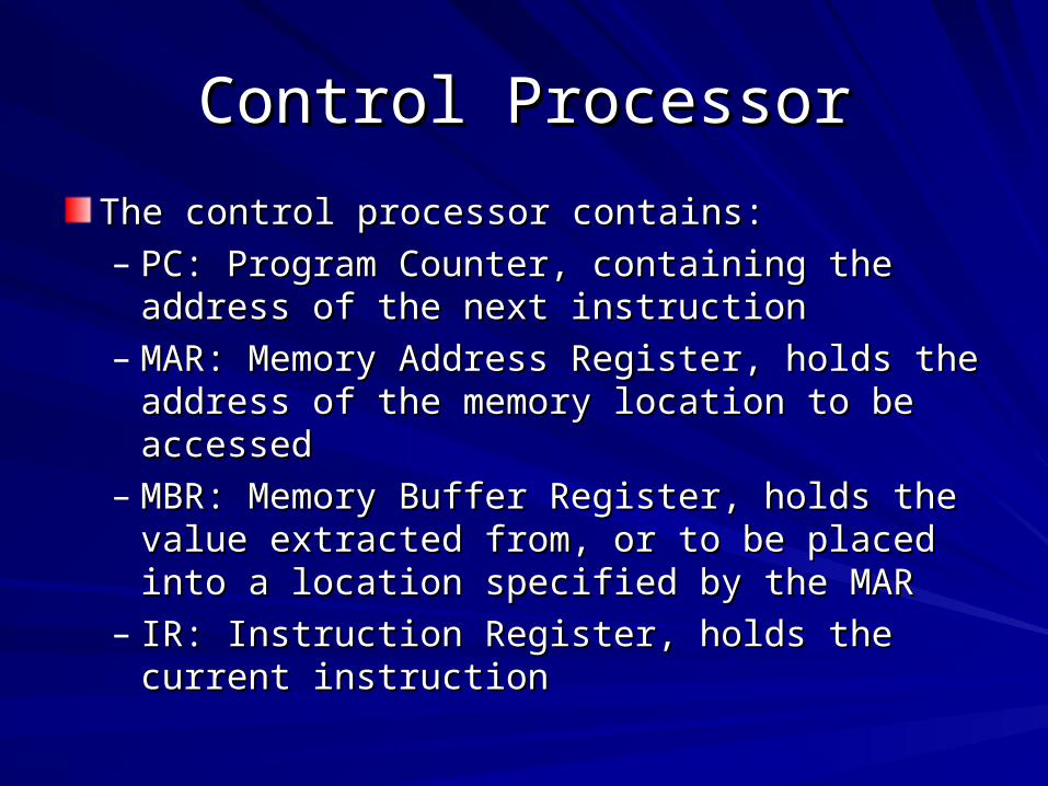
The control processor contains:The control processor contains:
– PC: Program Counter, containing the address PC: Program Counter, containing the address of the next instructionof the next instruction
– MAR: Memory Address Register, holds the MAR: Memory Address Register, holds the address of the memory location to be accessedaddress of the memory location to be accessed
– MBR: Memory Buffer Register, holds the value MBR: Memory Buffer Register, holds the value extracted from, or to be placed into a location extracted from, or to be placed into a location specified by the MARspecified by the MAR
– IR: Instruction Register, holds the current IR: Instruction Register, holds the current instructioninstruction
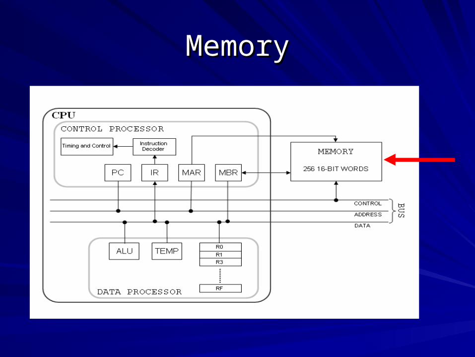
MemoryMemory

MemoryMemory
Memory is used to store Instructions and Memory is used to store Instructions and DataData– Data is stored sequentially from location 00 Data is stored sequentially from location 00
onwardsonwards– Instructions are stored sequentially from Instructions are stored sequentially from
location 10 onwardslocation 10 onwards
Has 16 bit memory with each memory Has 16 bit memory with each memory location labelled with an address between location labelled with an address between 00 and FF00 and FF

Input/Output DevicesInput/Output Devices
I/O Devices are used in Read and Write I/O Devices are used in Read and Write operationsoperations– Read user inputRead user input– Write output to the screenWrite output to the screen

Fetch-Execution CycleFetch-Execution Cycle
Fetch instruction from memory then execute the Fetch instruction from memory then execute the instruction: 4 step cycleinstruction: 4 step cycle
1: Transfer contents of PC to MAR to prepare from reading 1: Transfer contents of PC to MAR to prepare from reading the next instructionthe next instruction
[pc] -> [mar][pc] -> [mar]2: Contents of MAR used as an address in memory. The 2: Contents of MAR used as an address in memory. The
contents of the memory location (an instruction) are contents of the memory location (an instruction) are transferred to the MBRtransferred to the MBR
mem[[mar]] -> [mbr]mem[[mar]] -> [mbr]3: Instruction transferred to IR for execution3: Instruction transferred to IR for execution
[mbr] -> [ir][mbr] -> [ir]4: PC incremented by 1 and instruction code in IR is executed4: PC incremented by 1 and instruction code in IR is executed
[pc]+1 -> [pc][pc]+1 -> [pc]
TOY instruction representationTOY instruction representation
Each instruction consists of 4 hex digits.Each instruction consists of 4 hex digits.The left-most digit encodes one of the 16 The left-most digit encodes one of the 16 opcodesopcodesThe second left-most digit refers to one of The second left-most digit refers to one of the 16 registers, which we refer to as the the 16 registers, which we refer to as the destination register (d)destination register (d)The two right-most digits depend on the The two right-most digits depend on the opcode being used, as each opcode has a opcode being used, as each opcode has a unique formatunique format

TOY instruction representationTOY instruction representation
Example: Instruction 1462Example: Instruction 14621: opcode 1: Add1: opcode 1: Add4: store result in register 44: store result in register 46: use value stored in register 66: use value stored in register 62: use value stored in register 22: use value stored in register 2Add value of register 6 to register 2 and put the Add value of register 6 to register 2 and put the
result in register 4result in register 4
OpcodeOpcode DestinationDestination Source (s)Source (s) Source (t)Source (t)
Format 1:

TOY instruction representationTOY instruction representation
Example: Instruction 9462Example: Instruction 9462
9: opcode 9: Store9: opcode 9: Store
4: use contents of register 44: use contents of register 4
62: store in memory location 6262: store in memory location 62
Store value of register 4 in memory location 62Store value of register 4 in memory location 62
OpcodeOpcode DestinationDestination AddressAddress
Format 2:

TOY instruction representationTOY instruction representation
Special InstructionsSpecial Instructions– Halt: 0000Halt: 0000
The first (left-most) 0 is interpreted as ‘quit the The first (left-most) 0 is interpreted as ‘quit the program’, the program quits, and the other 3 program’, the program quits, and the other 3 digits are not readdigits are not read
– Jump: E500Jump: E500The first E is interpreted as JUMP (got to a set The first E is interpreted as JUMP (got to a set instruction), 5 is interpreted as the instruction instruction), 5 is interpreted as the instruction to go to, the program jumps to this instruction, to go to, the program jumps to this instruction, and the other 2 bits are not readand the other 2 bits are not read

Operations: ArithmeticOperations: Arithmetic
Opcode 1: AddOpcode 1: Add– Example: 1CABExample: 1CAB– Add contents of registers A and B, and store Add contents of registers A and B, and store
the result in register Cthe result in register C
Opcode 2: SubtractOpcode 2: Subtract– Example: 2CABExample: 2CAB
Subtract contents of register B from contents Subtract contents of register B from contents of register A, and store the result in register Cof register A, and store the result in register C
Example Programs - Page 5

Operations: LogicalOperations: Logical
Opcode 3: ANDOpcode 3: AND– Determines if the integer is Odd (returns 1) or Determines if the integer is Odd (returns 1) or
even (returns 0)even (returns 0)– Example: 3BA1Example: 3BA1– AND the contents of register A and 1, and AND the contents of register A and 1, and
store the result in register Bstore the result in register B
Example Programs - Page 6
Operations: LogicalOperations: Logical
Opcode 4: XOROpcode 4: XOR– Changes the sign of an integer, positive Changes the sign of an integer, positive
becomes negative and negative becomes becomes negative and negative becomes positivepositive
– Example: 4BAFExample: 4BAF– XOR the contents of registers A and F, and XOR the contents of registers A and F, and
store the result in register Bstore the result in register B
Example Programs - Page 6

Operations: ShiftOperations: Shift
Opcode 5: Left ShiftOpcode 5: Left Shift– Shift bits to the left, add padding (0’s) to the Shift bits to the left, add padding (0’s) to the
right.right.– Left shift by 1 is equivalent to multiplying by 2Left shift by 1 is equivalent to multiplying by 2– Left shift by n is equivalent to multiplying by 2Left shift by n is equivalent to multiplying by 2nn
– Example: 5AA2Example: 5AA2– Contents of register A left shifted by contents Contents of register A left shifted by contents
of register 2, results stored back into register of register 2, results stored back into register AA
Example Programs - Page 7

Operations: ShiftOperations: Shift
Opcode 6: Right ShiftOpcode 6: Right Shift– Shift bits to the right, add padding (0’s or 1’s Shift bits to the right, add padding (0’s or 1’s
depending on the sign bit) to the left.depending on the sign bit) to the left.– Right shift by 1 is equivalent to dividing by 2 (and Right shift by 1 is equivalent to dividing by 2 (and
throw away the remainder)throw away the remainder)– Right shift by n is equivalent to dividing by 2Right shift by n is equivalent to dividing by 2n n (and (and
throw away the remainder)throw away the remainder)– Example: 6AA2Example: 6AA2– Contents of register A right shifted by contents of Contents of register A right shifted by contents of
register 2, results stored back into register Aregister 2, results stored back into register A
Example Programs - Page 7

Operations: ShiftOperations: ShiftRight ShiftRight Shift
Operations: MoveOperations: Move
Opcode 7: Load AddressOpcode 7: Load Address– Load a memory address to a register. This opcode Load a memory address to a register. This opcode
only permits 8bit integers (rather than the 16bit only permits 8bit integers (rather than the 16bit capacity)capacity)
Opcode 8: LoadOpcode 8: Load– Load data from memory to registersLoad data from memory to registers
Opcode 9: StoreOpcode 9: Store– Store data from registers to memoryStore data from registers to memory
Opcode A& B: Load Indirect & Store IndirectOpcode A& B: Load Indirect & Store Indirect– Allows manipulation of memory addressesAllows manipulation of memory addresses– Can deal with arraysCan deal with arrays
Example Programs - Page 8

Operations: ControlOperations: Control
Opcode C: Branch ZeroOpcode C: Branch Zero– If a given register has a value of 0, reset the PC to a If a given register has a value of 0, reset the PC to a
given addressgiven address(Use branches like IF statements)(Use branches like IF statements)
Opcode D: Branch PositiveOpcode D: Branch Positive– If a given register has a positive integer value, reset If a given register has a positive integer value, reset
the PC to a given addressthe PC to a given address
Opcode E: JumpOpcode E: Jump– Reset the PC to the contents of a given registerReset the PC to the contents of a given register
Opcode F: Jump & LinkOpcode F: Jump & Link– PC is examined and its value stored in a given PC is examined and its value stored in a given
register. PC then reset to desired addressregister. PC then reset to desired address
Example Programs - Page 9

Operations: IdiomsOperations: Idioms
Register-to-Register TransferRegister-to-Register Transfer– Copies a value from one register to another register.Copies a value from one register to another register.– Example: 1201Example: 1201
Copies the value of register 1 to register 2, by adding the value Copies the value of register 1 to register 2, by adding the value of register 1 to register 0 (which relies on register 0 always being of register 1 to register 0 (which relies on register 0 always being 0)0)
GoToGoTo– Directly changes the PCDirectly changes the PC– Example: C0F0Example: C0F0– Changes PC to F0 since register 0 is always 0Changes PC to F0 since register 0 is always 0
NoOpNoOp– No operation performed, space filler.No operation performed, space filler.– Example: 1000Example: 1000