Embed Size (px)
Citation preview
North Carolina Agricultural and Technical State University North Carolina Agricultural and Technical State University
Aggie Digital Collections and Scholarship Aggie Digital Collections and Scholarship
Theses Electronic Theses and Dissertations
2014
A Sustainable Industrial Waste Management Solution: Application A Sustainable Industrial Waste Management Solution: Application
Of Silica Fume To Enhance Asphalt Binder Rheological Properties Of Silica Fume To Enhance Asphalt Binder Rheological Properties
Nader T. Abutalib North Carolina Agricultural and Technical State University
Follow this and additional works at: https://digital.library.ncat.edu/theses
Recommended Citation Recommended Citation Abutalib, Nader T., "A Sustainable Industrial Waste Management Solution: Application Of Silica Fume To Enhance Asphalt Binder Rheological Properties" (2014). Theses. 214. https://digital.library.ncat.edu/theses/214
This Thesis is brought to you for free and open access by the Electronic Theses and Dissertations at Aggie Digital Collections and Scholarship. It has been accepted for inclusion in Theses by an authorized administrator of Aggie Digital Collections and Scholarship. For more information, please contact [email protected].
A Sustainable Industrial Waste Management Solution:
Application of Silica Fume to Enhance Asphalt Binder Rheological Properties
Nader T. Abutalib
North Carolina A&T State University
A thesis submitted to the graduate faculty
in partial fulfillment of the requirements for the degree of
MASTER OF SCIENCE
Department: Civil, Architectural and Environmental Engineering Department
Major: Civil Engineering
Major Professor: Dr. Ellie Fini
Greensboro, North Carolina
2014
i
The Graduate School North Carolina Agricultural and Technical State University
This is to certify that the Master’s Thesis of
Nader T. Abutalib
has met the thesis requirements of North Carolina Agricultural and Technical State University
Greensboro, North Carolina 2014
Approved by:
Dr. Ellie Fini Major Professor
Dr. Sameer Hamoush Committee Member
Dr. Taher Abu Lebdeh Committee Member
Dr. Sanjiv Sarin Dean, The Graduate School
Dr. Sameer Hamoush Department Chair

ii
© Copyright by
Nader T. Abutalib
2014
iii
Biographical Sketch
Nader T. Abutalib was born on Sep 26, 1985, in the city of Makkah in Saudi Arabia. His
love of engineering was discovered when he was in high school. While gaining basic knowledge
in engineering, he also excelled as a computer programmer. This combination allowed him to
continue his studies both in Saudi Arabia and abroad. In 2003, he was accepted in the civil
engineering specialization as an undergraduate student in Umm Al-Qurra University in Makkah.
In addition, he traveled overseas during summer sessions for computer programmer training on
programs such as AutoCAD and geographic information systems (GIS). With undergraduate
courses as his base and relevant knowledge in the field of civil engineering, he represented his
university in national competitions in Saudi Arabia. Abutalib completed his undergraduate
studies in 2008, earning a Bachelor's of Science degree in civil engineering.
In 2008, he had the opportunity to work in the Ministry of Municipal Affairs as a civil
engineer in his town. This experience created a passion in him to gain the knowledge and
credentials to work in this field. He worked in a variety of departments to provide public services
to the community, gaining experience with different methods of supporting the city
infrastructure.
In 2010, he realized that he has many traits and interests that would make him an
appropriate candidate for graduate studies. In order to continue his studies, he had to satisfy the
requirement for English proficiency. He earned a diploma of academic English from the Interlink
Language Center at UNC Greensboro.
With his initial interest in transportation engineering, he chose to continue his studies as a
graduate student in the Department of Civil Engineering at North Carolina A&T State
University. He was eager to become well-read in the area of transportation engineering and do

iv
his own research. Abutalib focused his research and studies on the inclusion of nano-particles in
asphalt binder to improve the rheological properties and aging susceptibility of asphalt. During
this study, he had the opportunity to attend appropriate classes to be able to cover the concept
and be well-prepared to achieve the target of his research.
v
Dedication
I would like to dedicate this thesis with my warm appreciation to my family: my father,
Mr. Turki Abutalib; my mother, Mrs. Zain Alsulimani; my wife, Mrs. Yosra Alsulimani; and my
brother, Mr. Mohammad Abutalib. The hard work that went into this thesis is a result of the
characteristics that have been instilled in me by my family, and I thank them for being with me
through the struggles that I faced.
I want to especially thank my mother, who encouraged me to achieve my goal and
supported me without hesitation in circumstances that were beyond her control. This dedication
is in appreciation to my mother, Mrs. Zain Alsulimani, with love.
vi
Acknowledgements
I would like to thank my advisor, Dr. Ellie Fini, who significantly prepared me to achieve
my goal. After she carefully reviewed my experience and looked at my sense of engineering, she
helped me to improve my knowledge and guided me to the appropriate classes to a great thought
of sustainable pavements. I would also like to thank Daniel Oldham and Albert Onochie, who are
members of Dr. Fini’s research team. They were knowledgeable on the topic and they did not
hesitate to help when I was asking. I would also like to acknowledge the valuable help from
Renaldo Walters, who helped with conducting my XRD and FTIR tests and analysis.
vii
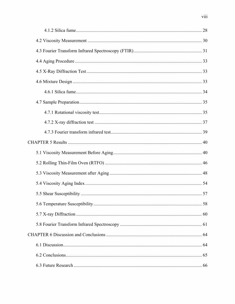
Table of Contents
List of Figures ................................................................................................................................. x
List of Tables ................................................................................................................................ xii
Abstract ........................................................................................................................................... 2
CHAPTER 1 Introduction ............................................................................................................... 3
1.1 Background ........................................................................................................................ 6
1.1.1 Asphalt binder (PG 64-22) ...................................................................................... 6
1.1.1.1 Components of asphalt pavement materials .................................................. 7
1.1.2 Silica fume ............................................................................................................... 7
1.1.2.1 Chemical properties of silica fume .............................................................. 10
1.1.2.2 Physical properties of silica fume ............................................................... 10
1.1.2.3 Standard specifications for silica fume ....................................................... 13
1.2 Objectives ........................................................................................................................ 13
1.3 Research Approach .......................................................................................................... 14
1.4 Research Scope ................................................................................................................ 15
CHAPTER 2 Literature Review ................................................................................................... 16
CHAPTER 3 Preliminary Study ................................................................................................... 20
3.1 Materials and Methods .................................................................................................... 20
3.2 Marshall Test ................................................................................................................... 20
3.3 Mixture Design ................................................................................................................ 21
3.4 Stability and Flow ............................................................................................................ 26
CHAPTER 4 Methodology ........................................................................................................... 28
4.1 Materials and Methods .................................................................................................... 28
4.1.1 Asphalt binders ...................................................................................................... 28
viii
4.1.2 Silica fume ............................................................................................................. 28
4.2 Viscosity Measurement ................................................................................................... 30
4.3 Fourier Transform Infrared Spectroscopy (FTIR) ........................................................... 31
4.4 Aging Procedure .............................................................................................................. 33
4.5 X-Ray Diffraction Test .................................................................................................... 33
4.6 Mixture Design ................................................................................................................ 33
4.6.1 Silica fume ............................................................................................................. 34
4.7 Sample Preparation .......................................................................................................... 35
4.7.1 Rotational viscosity test ......................................................................................... 35
4.7.2 X-ray diffraction test ............................................................................................. 37
4.7.3 Fourier transform infrared test ............................................................................... 39
CHAPTER 5 Results .................................................................................................................... 40
5.1 Viscosity Measurement Before Aging ............................................................................. 40
5.2 Rolling Thin-Film Oven (RTFO) .................................................................................... 46
5.3 Viscosity Measurement after Aging ................................................................................ 48
5.4 Viscosity Aging Index ..................................................................................................... 54
5.5 Shear Susceptibility ......................................................................................................... 57
5.6 Temperature Susceptibility .............................................................................................. 58
5.7 X-ray Diffraction ............................................................................................................. 60
5.8 Fourier Transform Infrared Spectroscopy ....................................................................... 61
CHAPTER 6 Discussion and Conclusions ................................................................................... 64
6.1 Discussion ........................................................................................................................ 64
6.2 Conclusions ...................................................................................................................... 65
6.3 Future Research ............................................................................................................... 66

ix
References ..................................................................................................................................... 68
x
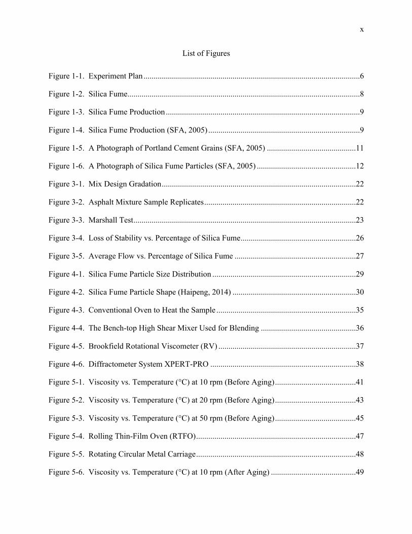
List of Figures
Figure 1-1. Experiment Plan ...........................................................................................................6
Figure 1-2. Silica Fume ...................................................................................................................8
Figure 1-3. Silica Fume Production ................................................................................................9
Figure 1-4. Silica Fume Production (SFA, 2005) ...........................................................................9
Figure 1-5. A Photograph of Portland Cement Grains (SFA, 2005) ............................................11
Figure 1-6. A Photograph of Silica Fume Particles (SFA, 2005) .................................................12
Figure 3-1. Mix Design Gradation ................................................................................................22
Figure 3-2. Asphalt Mixture Sample Replicates ...........................................................................22
Figure 3-3. Marshall Test ..............................................................................................................23
Figure 3-4. Loss of Stability vs. Percentage of Silica Fume .........................................................26
Figure 3-5. Average Flow vs. Percentage of Silica Fume ............................................................27
Figure 4-1. Silica Fume Particle Size Distribution .......................................................................29
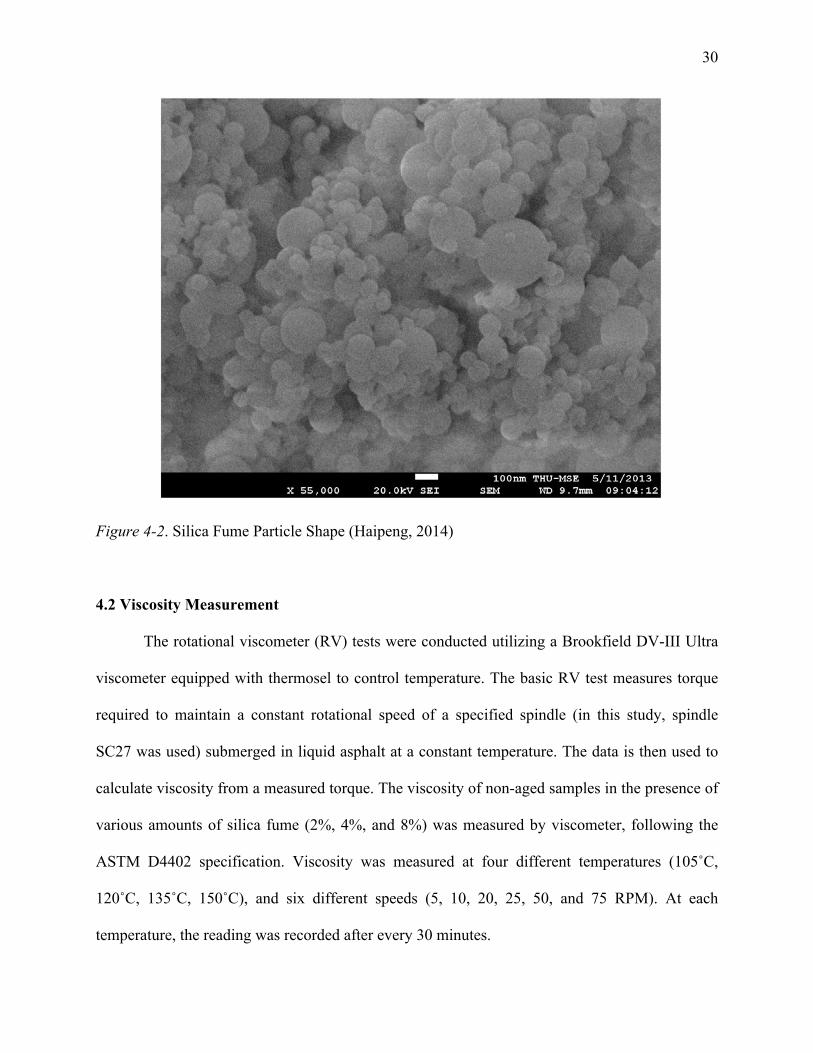
Figure 4-2. Silica Fume Particle Shape (Haipeng, 2014) .............................................................30
Figure 4-3. Conventional Oven to Heat the Sample .....................................................................35
Figure 4-4. The Bench-top High Shear Mixer Used for Blending ...............................................36
Figure 4-5. Brookfield Rotational Viscometer (RV) ....................................................................37
Figure 4-6. Diffractometer System XPERT-PRO ........................................................................38
Figure 5-1. Viscosity vs. Temperature (°C) at 10 rpm (Before Aging) ........................................41
Figure 5-2. Viscosity vs. Temperature (°C) at 20 rpm (Before Aging) ........................................43
Figure 5-3. Viscosity vs. Temperature (°C) at 50 rpm (Before Aging) ........................................45
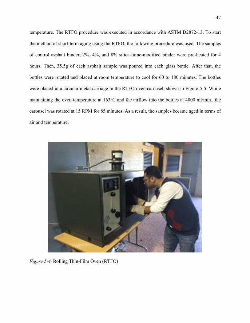
Figure 5-4. Rolling Thin-Film Oven (RTFO) ...............................................................................47
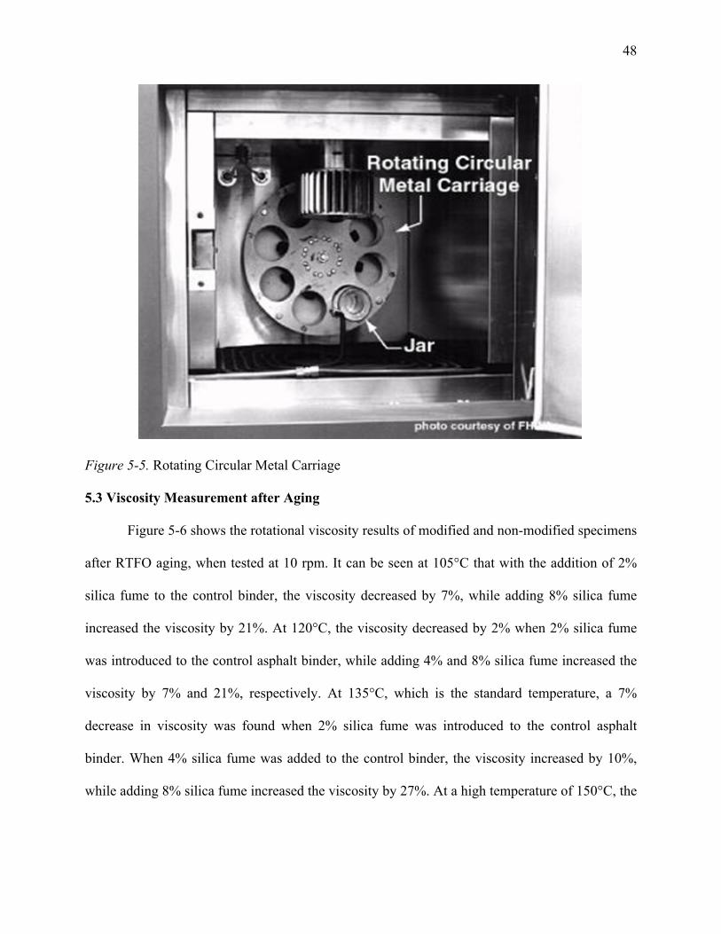
Figure 5-5. Rotating Circular Metal Carriage ...............................................................................48
Figure 5-6. Viscosity vs. Temperature (°C) at 10 rpm (After Aging) ..........................................49
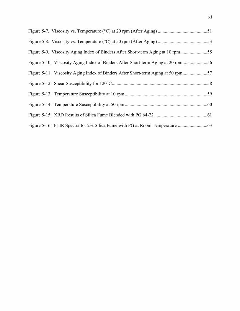
xi
Figure 5-7. Viscosity vs. Temperature (°C) at 20 rpm (After Aging) ..........................................51
Figure 5-8. Viscosity vs. Temperature (°C) at 50 rpm (After Aging) ..........................................53
Figure 5-9. Viscosity Aging Index of Binders After Short-term Aging at 10 rpm .......................55
Figure 5-10. Viscosity Aging Index of Binders After Short-term Aging at 20 rpm .....................56
Figure 5-11. Viscosity Aging Index of Binders After Short-term Aging at 50 rpm .....................57
Figure 5-12. Shear Susceptibility for 120°C .................................................................................58
Figure 5-13. Temperature Susceptibility at 10 rpm ......................................................................59
Figure 5-14. Temperature Susceptibility at 50 rpm ......................................................................60
Figure 5-15. XRD Results of Silica Fume Blended with PG 64-22 .............................................61
Figure 5-16. FTIR Spectra for 2% Silica Fume with PG at Room Temperature .........................63
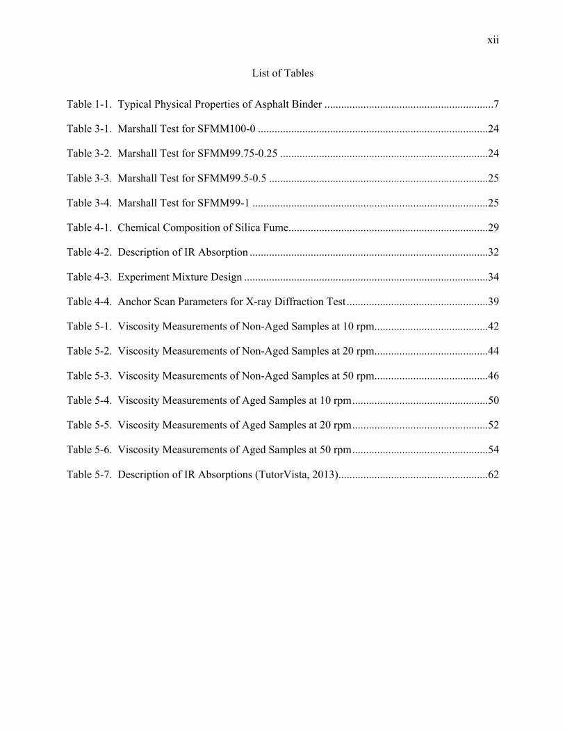
xii
List of Tables
Table 1-1. Typical Physical Properties of Asphalt Binder .............................................................7
Table 3-1. Marshall Test for SFMM100-0 ...................................................................................24
Table 3-2. Marshall Test for SFMM99.75-0.25 ...........................................................................24
Table 3-3. Marshall Test for SFMM99.5-0.5 ...............................................................................25
Table 3-4. Marshall Test for SFMM99-1 .....................................................................................25
Table 4-1. Chemical Composition of Silica Fume ........................................................................29
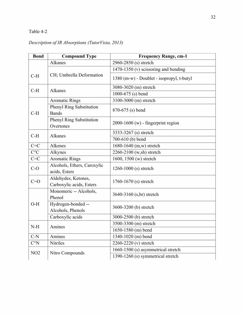
Table 4-2. Description of IR Absorption ......................................................................................32
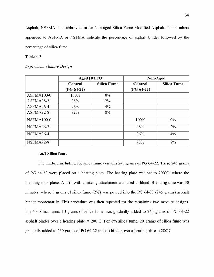
Table 4-3. Experiment Mixture Design ........................................................................................34
Table 4-4. Anchor Scan Parameters for X-ray Diffraction Test ...................................................39
Table 5-1. Viscosity Measurements of Non-Aged Samples at 10 rpm .........................................42
Table 5-2. Viscosity Measurements of Non-Aged Samples at 20 rpm .........................................44
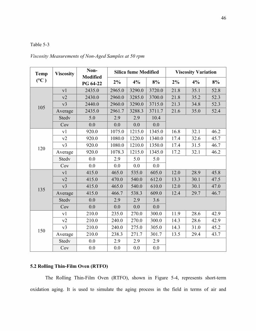
Table 5-3. Viscosity Measurements of Non-Aged Samples at 50 rpm .........................................46
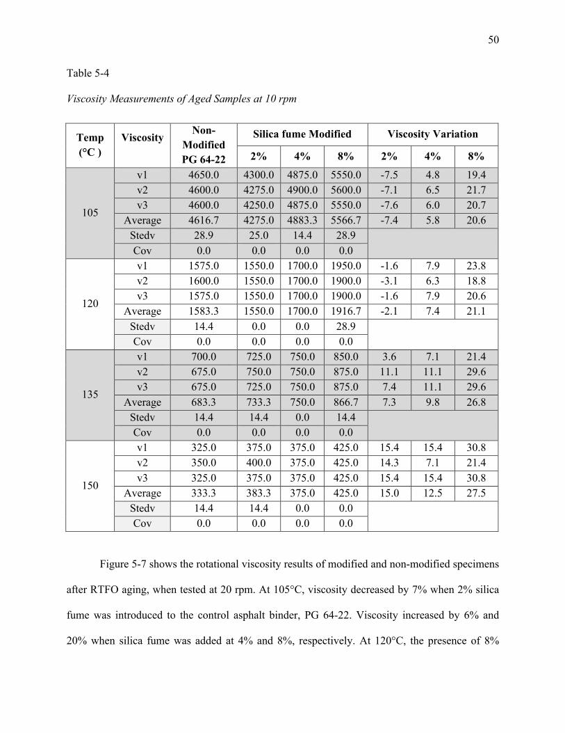
Table 5-4. Viscosity Measurements of Aged Samples at 10 rpm .................................................50
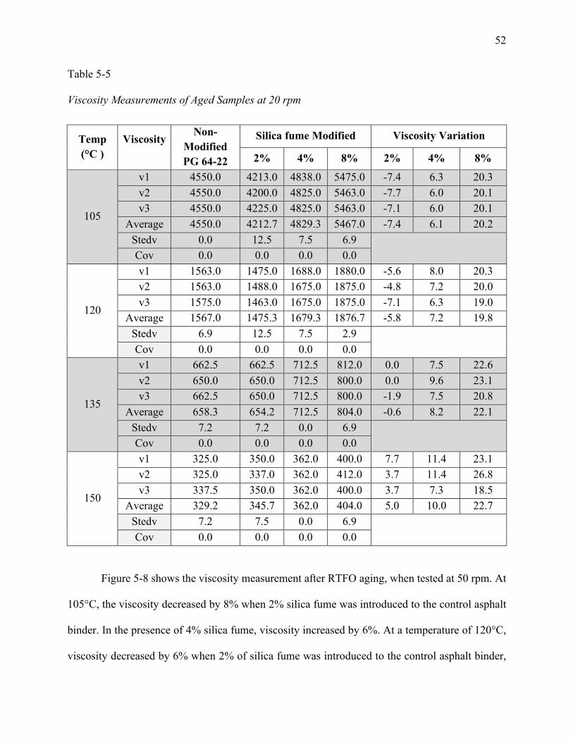
Table 5-5. Viscosity Measurements of Aged Samples at 20 rpm .................................................52
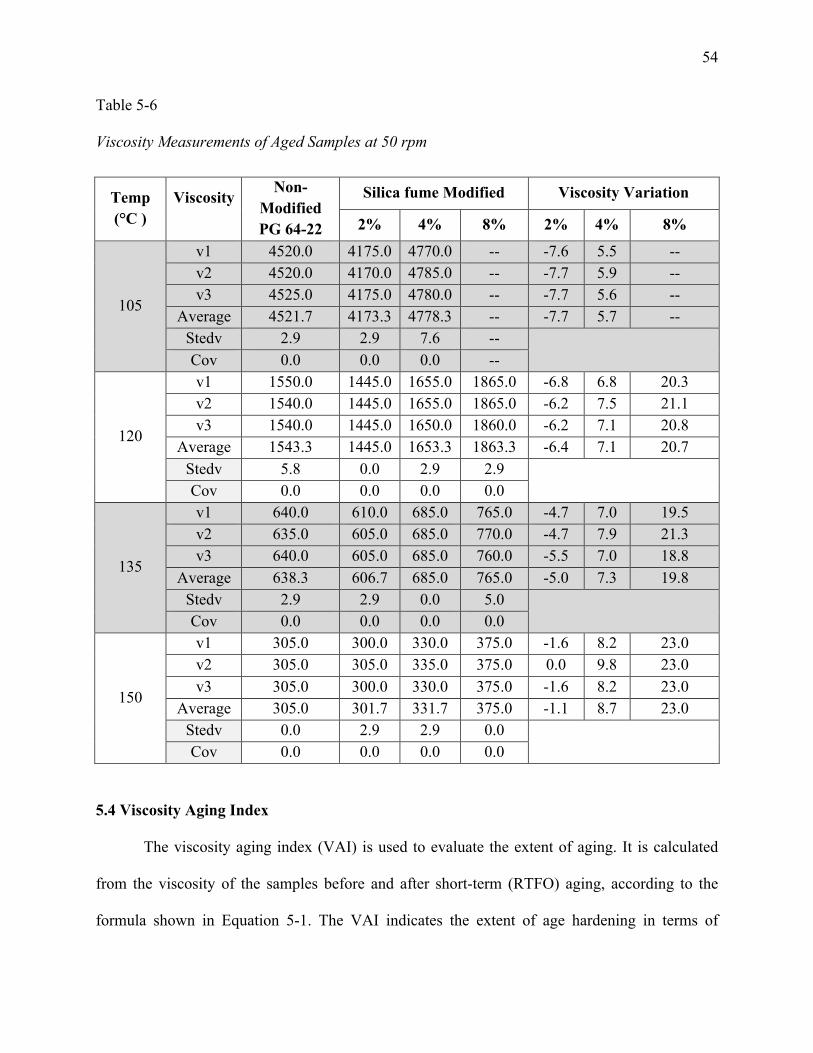
Table 5-6. Viscosity Measurements of Aged Samples at 50 rpm .................................................54
Table 5-7. Description of IR Absorptions (TutorVista, 2013) ......................................................62
2
Abstract
This thesis investigates the practical feasibility of using silica fume, an industrial waste material,
to enhance the rheological properties of asphalt binder. It has been widely reported that asphalt
binder oxidation reduces the service life of asphalt pavement by negatively impacting its
rheological properties. When asphalt binder is oxidized, its viscoelastic properties are
diminished; this can be evidenced by the reduction in asphalt phase angle as measured through
dynamic shear and torsion tests. This can lead to a more brittle pavement, which is more prone
to cracks due to thermal stress and traffic loading and leads to premature pavement failure. In
this thesis, the effectiveness of the application of silica-fume-based additives to reduce asphalt
oxidative aging is investigated. It is hypothesized that fine-graded silica fume with nano- to
micro-level particle size can be used to reduce asphalt oxidation. To test this hypothesis, various
percentages of silica fume were introduced to base binders; then a series of experiments in binder
and mixture level was conducted to evaluate the effects of silica fume addition. In the binder
level, silica fume was concentrated in asphalt binder with percentages of 2%, 4%, and 8% for
both aged and non-aged samples. A rotational viscometer (RV) was used to study the effects of
silica fume on high-temperature properties of asphalt binder. FTIR analysis was used to
determine the chemical compounds of silica-fume-modified asphalt matrix. The Marshall
stability test was used to evaluate the stability of the asphalt mixture in the presence of silica
fume. Analysis of the experiment results showed that silica fume reduced the asphalt aging index
significantly; in addition, the temperature susceptibility of asphalt binder was reduced as the
percentage of silica fume increased. The positive effect of silica fume on base asphalt’s
rheological properties could be attributed to the high surface area of the silica fume accompanied
by its granular particles with high polarity.
3
CHAPTER 1
Introduction
It has been well reported that asphalt aging is mainly associated with oxidation at the
molecular level. The increased oxidation has been shown to decrease the service life of roads.
When asphalt binder is oxidized, its viscoelastic properties are diminished; this can be evidenced
by the reduction in asphalt phase angle as measured through dynamic shear and torsion tests.
This in turn can lead to a more brittle pavement, which is more prone to cracks due to thermal
stress and traffic loading and leads to premature pavement failure. This phenomenon is known to
be expedited at high temperature, accompanied by loss of asphalt volatile compounds. Oxidation
affects molecular chains in the pavement, leading to their breakdown as well as creating new
chemical compounds, including carbonyl and sulfoxide compounds that are naturally present in
asphalt binder. These in turn lead to an increase in asphalt binder viscosity while reducing its
phase angle as the oxidation progresses. This results in a stiffer and more brittle material (Huang
et al., 2012). In this thesis, the effectiveness of the application of silica-fume-based additives to
reduce asphalt oxidative aging is investigated. It is hypothesized that fine-graded silica fume
with nano- to micro-level particle size can be used to reduce asphalt oxidation, creating a new
generation of asphalt pavement with higher resistance to oxidative aging.
Polymers have a variety of applications that have led researchers to investigate polymers
to address many of today’s problems. High temperature causes erosion and decays most man-
made structures, including roads. The presence of water weakens the molecular bonds between
asphalt and its aggregate parts. Moisture leads to breakdown of the molecular chains in the
pavement, causing holes and the need for repaving (Yildirim, 2007). Repaving costs money and
4
time, and increases the amount of VOCs (volatile organic compounds) that are released into the
atmosphere.
Nano-silica has been highly used in the polymer industry to increase mechanical and
physical properties of base materials such as stiffness, toughness, strength, and thermal stability
(Lee et al., 2005). Recently, there have been studies on the use of various nano-particles to
modify asphalt binders; for instance, it has been shown that nano-clay can be an effective
additive for use in asphalt binder (Onochie et al., 2013). Furthermore, studies reported that the
presence of layered silicate montmorillonite (MMT) nano-clay in asphalt binder can significantly
reduce asphalt oxidative aging, provided that intercalation or exfoliation of silicate layers can be
achieved. Typically, intercalation or exfoliation has been facilitated using nano-clay
modification. A modification that has been reported effective in facilitating exfoliation of
silicate layers has been organo-modification of clay particles (Yu et al., 2010). The level of
exfoliation has been monitored mainly by measuring the spacing of silicate layers using X-ray
diffraction.
Other studies have used nano-silica to achieve a highly polar surface and reported that
nano-silica can be very effective in reducing the aging rate while enhancing resistance to rutting
and cracking (Amerkhanian et al., 2010). In fact, modifiers such as silica fume have the
capability to enhance the aging resistance of asphalt binder as well as extend the asphalt’s high-
and low-temperature workability. However, to achieve such improvements, it is critical to
ensure uniform blending of nano-silica into the asphalt matrix. Agglomeration of nano-silica
particles has been reported to be an issue for such applications. Therefore, this study investigates
the effectiveness of silica fume in the form of a granulated industrial waste with highly polar
surface area to enhance blending and improve asphalt oxidation resistance.
5
It has been reported that approximately 5.11 million tons of silica fume were produced in
2010, and 4.78 million tons in 2012. Since silica fume is a frequently available industrial waste
(Haipeng, 2014), its application in asphalt paving could facilitate industrial waste management
while improving asphalt sustainability and performance. Silica fume is a very fine pozzolanic
material with an average particle size of 100 – 200 nm. It is extracted from gases produced while
making silicon or ferrosilicon alloy at 1750°C. The exhaust dust from the smoke is then collected
on electrostatic filters as silica fume (SFA, 2005). Silica fume is made of extremely fine
granulated particles that have very high silica content. Its surface area ranges from 60,000 to
150,000ft2/lb, and it has a specific gravity of 2.20. Silica fume is categorized as nano-particles
because of the size ranges and particle shape. Due to its polarity and high surface area, it can be
used as an additive in asphalt binder to improve the properties of the asphalt binder (Markovic
and Mikoc, 2010).
This thesis focuses on using silica fume as an additive to enhance the rheological
properties of asphalt binder. Using penetration grade 60-70 asphalt binder, five asphalt mixtures
were made containing silica fume: 0.25%, 0.5%, and 1% silica fume were incorporated. These
modified mixtures were tested along with a control sample (without silica fume) to determine the
stability and flow. In the binder level, the base asphalt binder PG 64-22, which is commonly
used in North Carolina, was used for the study. Modified specimens were made by incorporating
2%, 4%, and 8% of silica fume into the aforementioned base asphalt. Modified and non-modified
asphalt binders were compared in terms of their viscosity, shear, and temperature susceptibility
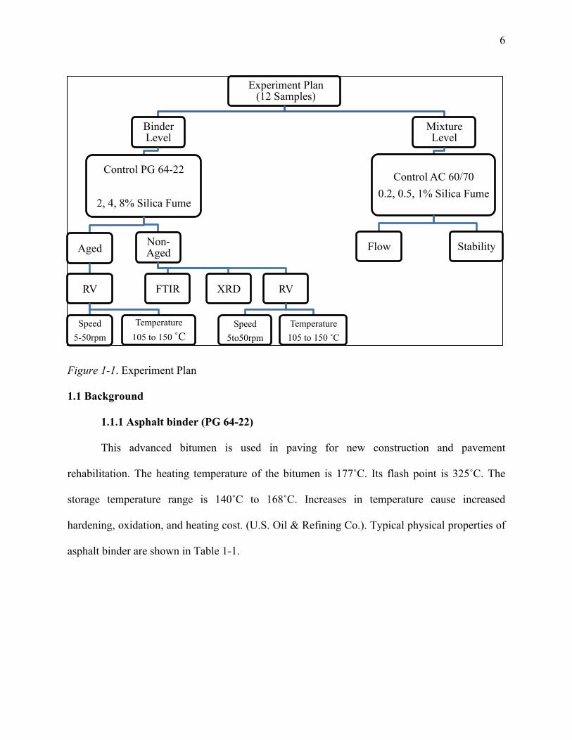
before and after being exposed to oxidative aging. Figure 1-1 shows the experiment plan of this
study, with a total of 12 samples: 4 samples were used in the mixture level, and 8 samples were
used in the binder level.
6
Figure 1-1. Experiment Plan 1.1 Background
1.1.1 Asphalt binder (PG 64-22)
This advanced bitumen is used in paving for new construction and pavement
rehabilitation. The heating temperature of the bitumen is 177˚C. Its flash point is 325˚C. The
storage temperature range is 140˚C to 168˚C. Increases in temperature cause increased
hardening, oxidation, and heating cost. (U.S. Oil & Refining Co.). Typical physical properties of
asphalt binder are shown in Table 1-1.
Experiment Plan (12 Samples)
Binder Level
Control PG 64-22
2, 4, 8% Silica Fume
Aged
RV
Speed 5-50rpm
Temperature 105 to 150 ˚C
Non-Aged
FTIR XRD RV
Speed
5to50rpm
Temperature 105 to 150 ˚C
Mixture Level
Control AC 60/70 0.2, 0.5, 1% Silica Fume
Flow Stability
7
Table 1-1
Typical Physical Properties of Asphalt Binder (ASTM International, 2013)
Property Test Method Value
Flash Point, °C
Cleveland Open
Cup
ASTM D92,
EN 22592 (b)
Varies according to grade,
Typically > 230°C (445°F).
> 270°C (520°F) in ASTM D312,
> 250°C (482°F) in EN 13304
Loss on Heating, %
m
(Maximum)
ASTM D2872,
EN 12607-1
0.5-1% maximum depending upon the specification
Specific gravity
value
ASTM D70
EN 15326
≥ 0.95, typically > 1.0, not a specification
Solubility, %
(Minimum)
ASTM D2042,
EN 12592
≥ 0.99% m by specification
(Trichloroethylene, Toluene, or Xylene as specified)
Solubility in water Negligible
Softening Point ASTM D86,
EN 1427
> 30°C (86°F, grade dependent
Vapor Pressure Below detection limit at ambient temperature
1.1.1.1 Components of asphalt pavement materials
Asphalt is made of bitumen or modified polymer bituminous binder, additives
such as bonding and stripping agents, and air. Other particles such as fibers, crumb rubber,
glass, slag, or silica fume could be added to asphalt to reduce the risk of rutting, low temperature
cracking, and fatigue cracking (You et al., 2011), (Yu et al., 2010).
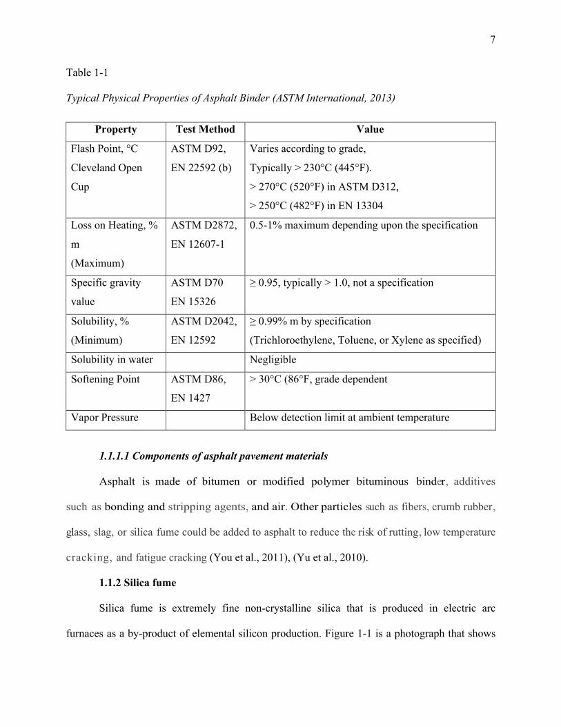
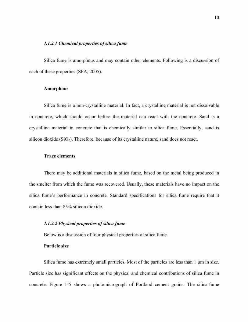
1.1.2 Silica fume
Silica fume is extremely fine non-crystalline silica that is produced in electric arc
furnaces as a by-product of elemental silicon production. Figure 1-1 is a photograph that shows
8
the color of silica fume. It shows typical silica fume as it is collected from a furnace. Usually,
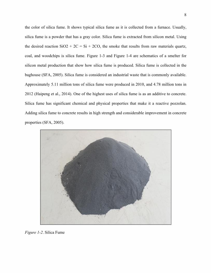
silica fume is a powder that has a gray color. Silica fume is extracted from silicon metal. Using
the desired reaction SiO2 + 2C = Si + 2CO, the smoke that results from raw materials quartz,
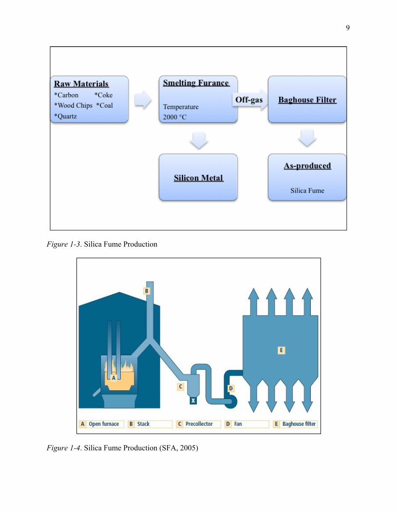
coal, and woodchips is silica fume. Figure 1-3 and Figure 1-4 are schematics of a smelter for
silicon metal production that show how silica fume is produced. Silica fume is collected in the
baghouse (SFA, 2005). Silica fume is considered an industrial waste that is commonly available.
Approximately 5.11 million tons of silica fume were produced in 2010, and 4.78 million tons in
2012 (Haipeng et al., 2014). One of the highest uses of silica fume is as an additive to concrete.
Silica fume has significant chemical and physical properties that make it a reactive pozzolan.
Adding silica fume to concrete results in high strength and considerable improvement in concrete
properties (SFA, 2005).
Figure 1-2. Silica Fume
9
Figure 1-3. Silica Fume Production
Figure 1-4. Silica Fume Production (SFA, 2005)
10
1.1.2.1 Chemical properties of silica fume
Silica fume is amorphous and may contain other elements. Following is a discussion of
each of these properties (SFA, 2005).
Amorphous
Silica fume is a non-crystalline material. In fact, a crystalline material is not dissolvable
in concrete, which should occur before the material can react with the concrete. Sand is a
crystalline material in concrete that is chemically similar to silica fume. Essentially, sand is
silicon dioxide (SiO2). Therefore, because of its crystalline nature, sand does not react.
Trace elements
There may be additional materials in silica fume, based on the metal being produced in
the smelter from which the fume was recovered. Usually, these materials have no impact on the
silica fume’s performance in concrete. Standard specifications for silica fume require that it
contain less than 85% silicon dioxide.
1.1.2.2 Physical properties of silica fume
Below is a discussion of four physical properties of silica fume.
Particle size
Silica fume has extremely small particles. Most of the particles are less than 1 µm in size.
Particle size has significant effects on the physical and chemical contributions of silica fume in
concrete. Figure 1-5 shows a photomicrograph of Portland cement grains. The silica-fume
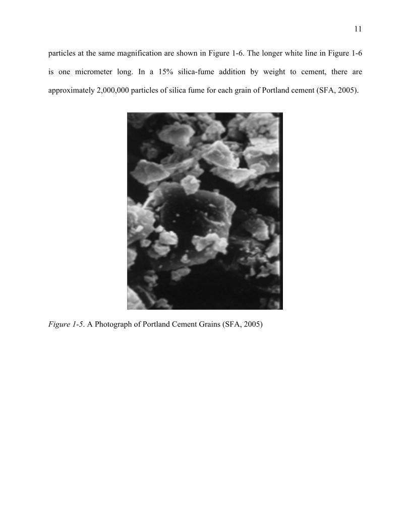
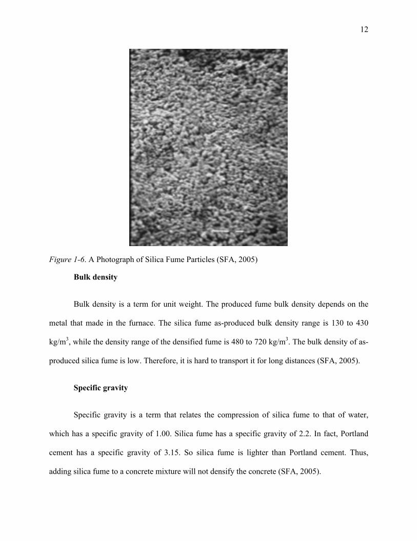
11
particles at the same magnification are shown in Figure 1-6. The longer white line in Figure 1-6
is one micrometer long. In a 15% silica-fume addition by weight to cement, there are
approximately 2,000,000 particles of silica fume for each grain of Portland cement (SFA, 2005).
Figure 1-5. A Photograph of Portland Cement Grains (SFA, 2005)
12
Figure 1-6. A Photograph of Silica Fume Particles (SFA, 2005)
Bulk density
Bulk density is a term for unit weight. The produced fume bulk density depends on the
metal that made in the furnace. The silica fume as-produced bulk density range is 130 to 430
kg/m3, while the density range of the densified fume is 480 to 720 kg/m3. The bulk density of as-
produced silica fume is low. Therefore, it is hard to transport it for long distances (SFA, 2005).
Specific gravity
Specific gravity is a term that relates the compression of silica fume to that of water,
which has a specific gravity of 1.00. Silica fume has a specific gravity of 2.2. In fact, Portland
cement has a specific gravity of 3.15. So silica fume is lighter than Portland cement. Thus,
adding silica fume to a concrete mixture will not densify the concrete (SFA, 2005).
13
Surface area
Surface area of a material mass gives the result of specific surface. Silica fume particles
are extremely small. Therefore, silica fume has a high surface area of 15,000 to 30,000 m2/kg. In
fact, water demand increases for sand as the particles become smaller, the same as for silica
fume. Thus, it is necessary to use silica fume in combination with a water-reducing admixture.
The Silica Fume Association indicated that a “specialized test called the “BET method” or
“nitrogen adsorption method” must be used to measure the specific surface of silica fume.
Specific surface determinations based on sieve analysis or air-permeability testing are
meaningless for silica fume”.
1.1.2.3 Standard specifications for silica fume
There are two standard specifications for silica fume: ASTM-C-1240, which is the
Standard Specification for Silica Fume Used in Cementitious Mixtures; and AASHTO-M-307,
which is the Standard Specification for Use of Silica Fume as a Mineral Admixture in Hydraulic-
Cement Concrete, Mortar, and Grout.
Each of these specifications contains both mandatory and optional elements. The ASTM-
C-1240 and AASHTO-M-307 specifications were derived from other pozzolan specifications
such as ASTM-C-618, Standard Specification for Raw Natural Pozzolan and Coal Fly Ash for
Use in Concrete. The Silica Fume Association has shown that “because of this origin, some of
the requirements for silica fume are actually more appropriate for other pozzolanic materials.
Over time these elements of the specifications are being revised or removed.”
1.2 Objectives
The research study in this thesis focuses on evaluating the effects of adding different percentages
of silica fume on the rheological properties and aging susceptibility of asphalt binder:
14
• Determine the viscosity of silica-fume-modified asphalt binder when 2%, 4%, and 8%
(weight of dry mass) silica fume are added to virgin asphalt binder (PG 64-22).
• Determine the flow and loss of stability of silica-fume-modified asphalt mixture when
0.25%, 0.5%, and 1% (weight of dry mass) silica fume are added to asphalt (60-70).
• Determine the crystalline structure of the silica-fume-modified binder.
• Determine the chemical bonds in the silica-fume-modified binder.
1.3 Research Approach
The hypothesis of this research is that the inclusion of silica fume in asphalt binder
enhances asphalt binder’s rheological properties and reduces its aging susceptibility. To test this
hypothesis, the following research approach was considered to evaluate the rheological
characteristics and chemical bonds in control asphalts and asphalts modified with three selected
percentages of silica fume:
· Rotational Viscosity (RV) test
RV is the abbreviation for rotational viscometer. The RV test was conducted according to
the ASTM D4402 standard specification using the Brookfield rotational viscometer.
Tests were conducted at 120°C, 135°C, and 150°C. In this study, test results were used to
compare dynamic shear viscosity among the asphalt modifications.
· X-Ray Diffraction test
This test was conducted using a diffractometer system. This test is used to characterize
polycrystalline structure of materials. The powder diffraction identifies components in a
sample by procedure matching. In this study, test results were used to determine the
crystallography of the tested mixtures. Data was collected between the angles of 4 and 60
15
2Theta for a period of two hours for each sample. For silica fume samples, 0.04 RAD
soller slits were used, which increase the intensity of the X-Ray beam. The soller slit job
is to take a line source of radiation and distribute it into smaller beams, leading to
reduced axial divergence of the beam.
· Fourier Transform Infrared (FTIR) spectroscopy test
FTIR was used to determine the unknown chemical bonds of silica fume that have
occurred due to the synthesis of material. This test was conducted at room temperature
for all samples. This test can be used to determine the stability of a substance.
1.4 Research Scope
Chapter 1 describes the purpose of the research, the study objectives, and the hypothesis.
Chapter 2 contains a literature review. Chapter 3 describes the preliminary study to investigate
the workability of adding silica fume to an asphalt mixture. In Chapter 4, the approaches have
been tested to measure rheological characteristics of modified and non-modified asphalt in the
binder level. It also presents the material properties of silica fume. Chapter 5 discusses the test
procedures and results from each of the tests that have been mentioned. Chapter 6 contains
discussion and conclusions of the research.
16
CHAPTER 2
Literature Review
There have been many studies on investigating asphalt binder oxidation mechanisms;
many researchers tried to develop modifiers and additives to enhance asphalt binder’s resistance
to oxidative aging. Oxidative aging of asphalt binder is expedited when heated at the application
temperature and mixed with stone aggregates; this usually is accompanied by significant loss of
volatile compounds, while giving rise to carbonyl and sulfoxide compounds in asphalt (Lu and
Isacsson, 2002).
Asphalt binder properties could be negatively affected by oxidative aging, diminishing
the binder’s rheological properties and leading to premature pavement cracking. Therefore, it is
important to reduce the level of asphalt oxidation during both asphalt application and pavement
service life. Asphalt is one of the main components used in highway and airport pavements;
more than 90% of roads in the U.S. are made of asphalt pavement, and the rest are concrete.
Worldwide annual consumption of asphalt in 2013 was 150 million tons, making it an 80 billion
dollar industry. In the U.S., generally 90% of liquid asphalt is used for road paving and
approximately 10% is used for roofing products, with other specialty applications accounting for
only a very small fraction of consumption (SBI, 2009).
Using polymers for asphalt binder modification has become the standard in ideal
pavement design, especially in the United States, Canada, Europe, and Australia. There are many
polymers, such as rubber, SBR, SBS, and Elvaloy that have been used in the specifications
designed to modify binders. The elastic recovery test provides valuable results once polymers are
present in an asphalt binder (Yildirim, 2007). Asphalt has been studied by many associations and
researchers looking for the best way to resist rainfall and ground water impacts, and improve
17
asphalt properties for high quality pavement. It is crucial to play a proactive role in maintaining
pavement by preventing problems before they start. From day one, as soon as asphalt pavement
is installed, numerous factors are working to deteriorate the pavement surfaces. Asphalt begins
aging the minute it is laid, as oxidation causes the oil in the binder to evaporate. At first, this is
good, because it allows the asphalt to cure. Eventually, though, the pavement gets too dry,
leading to raveling and hairline cracks. Before these cracks begin to develop, or while they are
still small, an asphalt seal coat should be applied by a professional seal coat contractor. Asphalt
is the term used to describe a mixture of bitumen (oil) with aggregate (rock) (Parviz, 2011).
Asphalt may also contain other additives such as emulsifiers, cutback agents, polymers, etc.
Asphalt pavement is this mixture placed and compacted over a base course or a sub base course,
or both. This pavement is also referred to as a pavement structure in that each course (surface,
base, sub-base) will act structurally and each provides support to the given loading.
Considering liquid asphalt’s wide applications mainly for outdoor applications and in
various environmental conditions, developing techniques and methodology to reduce the rate of
asphalt oxidative aging is critical. New efforts and studies of materials engineered at the nano-
scale in other engineering fields may well lead to major improvements in the mechanical and
physical properties as well as the durability of composite construction materials. Application of
such technology in the field of asphalt in order to address issues such as oxidation has received
significant attention recently. Thus, many researchers investigated various nano-particles as
modifiers to prevent oxidative aging; among those, nano-clay and nano-silica were found to be
effective in reducing the asphalt aging index (Onochie et al., 2013). This thesis investigates the
merits of application of very fine granulated silica particles (100nm - 200nm) to reduce oxidative
aging of asphalt binder.
18
The effects of using silica fume in cementitious products such as concrete, grouts, and
mortars as well as elastomer, polymer, refractory, ceramic, and rubber applications has been well
documented (Khayat et al., 1997). In cementitious compounds, silica fume initiates a chemical
reaction called the pozzolanic reaction. The hydration of Portland cement produces compounds
such as calcium silicate hydrates (CSH) and calcium hydroxide (CH), whose formation is linked
to strength development in concrete. When silica fume is added to fresh concrete, it chemically
reacts with the CH to produce additional CSH. This in turn can enhance compressive strength
and chemical resistance. The additional CSH produced by silica fume is more resistant to
aggressive chemicals than the weaker CH compounds (Langan et al., 2002). While there have
been several attempts to use silica fume in concrete, its application in asphalt pavement has not
been studied. While modification with a few nano-materials has been found to be effective, the
asphalt industry is very cost sensitive, and the high price of such nano-materials may hinder their
application despite their effectiveness.
Selected nano-particles for pavement application should be non-hazardous, low cost, easy
to handle, and available in large quantities, regardless of geographical locations. Nano-particles
should also fulfil ecological requirements such as low energy consumption and environmental
compatibility. Furthermore, they should significantly improve long-term performance and
functional properties of the base asphalt (Yildirim, 2007).
Mikoc and Markovic characterized the influence of slag, fly ash, and silica fume on the
mechanical and physical properties of asphalt mixtures, using the HRN EN 12697 standard
(Markovic and Mikoc, 2010). They concluded that use of slag as an aggregate in asphalt
mixtures increases the density and stability of the mixture. The replacement of aggregates and
19
fillers with waste materials could also lead to cost savings in the production of asphalt mixtures
and contribute to its environmental sustainability (You et al., 2011).
Similar research has been performed on high-temperature rheological properties of the
binders containing various percentages of carbon nano-particles (Amirkhanian et al., 2010).
Their results indicated that the viscosity of binders increased proportionally with the percentage
of nano-particles, failure temperature increased in the presence of nano-particles, and the elastic
and viscous modulus values increased with the addition of nano-particles.
20
CHAPTER 3
Preliminary Study
In this chapter, asphalt binder AC 60-70 and silica fume are characterized based on
supplier specifications.
3.1 Materials and Methods
The test materials used in this study were asphalt binder penetration grade AC 60-70 and
industrial waste silica fume. Four mixtures were made using asphalt 60-70 in the presence of
0.25%, 0.5%, and 1% silica fume. The base binder for this study was penetration grade AC 60-
70. Asphalt binder 60-70 is a base binder that is used in high-temperature areas such as Saudi
Arabia. The silica fume is considered as an industrial waste material. The Silica fume has
physical and chemical properties could lead to improve the mixture properties in terms of
stability and density.
3.2 Marshall Test
The Marshall test provides the performance prediction measure for the Marshall mix
design method. The stability and flow tests were conducted. The stability portion of the test
measures the maximum load supported by the test specimen at a loading rate of 50.8 mm/minute
(2 inches/minute). Basically, the load is increased until it reaches a maximum point at which the
specimen fails and the load is recorded (Roberts et al., 1996). The test is to determine the
stability and flow of compacted samples of asphalt mixture and determine the optimal ratio of
asphalt. Samples were immersed in a bath with water temperature of 60 ± 1 ºC and held between
40 and 60 minutes. The samples were then tested using the Marshall stability test. The stability
of asphalt samples was determined by the maximum resistance to deformation. The base asphalt
used was AC 60-70 in the presence of 0.25%, 0.5%, or 1% silica fume. The stability and flow of
21
modified specimens were then compared with those measures of control samples without silica
fume.
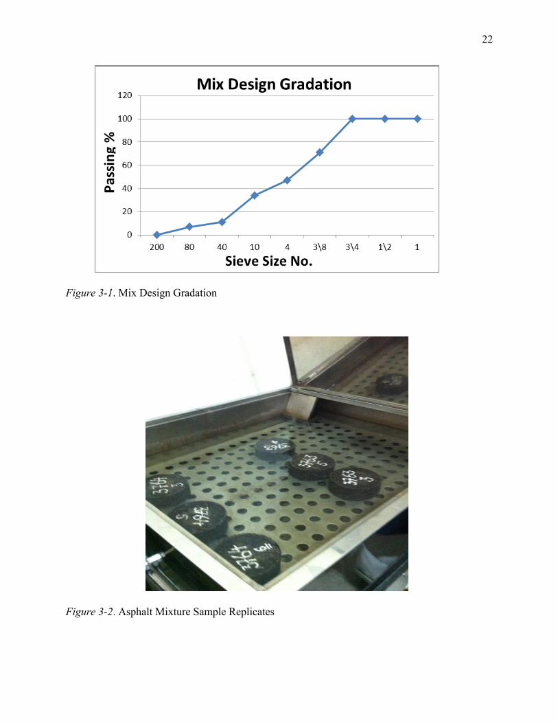
3.3 Mixture Design
Asphalt AC 60-70 was mixed with the stone aggregates following the mix gradation
design that is shown in Figure 3-1. Silica fume was then added to the mixture at levels of 0.25%,
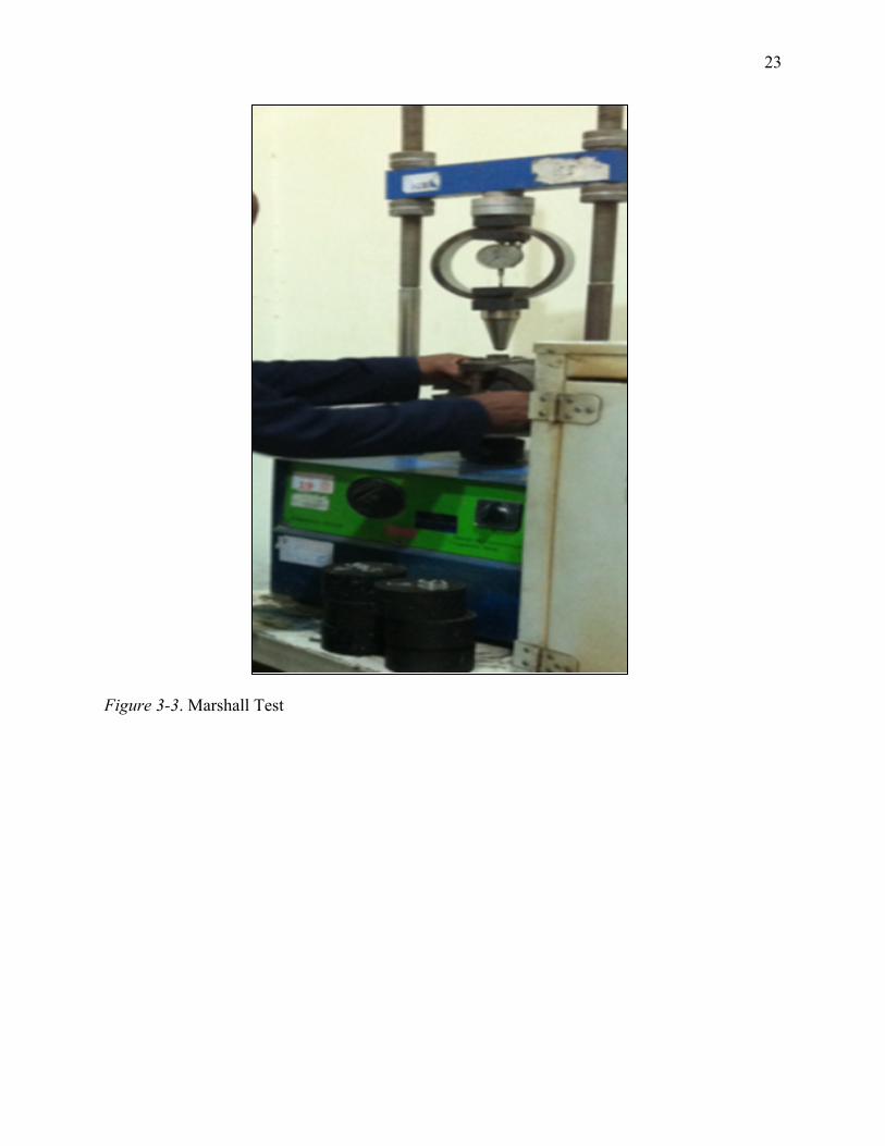
0.5, and 1% by weight. Four samples were used in this study. Figure 3-2 shows that six replicates
of each sample were considered to ensure significant results. The air weight was measured.
Then, the weight of the sample in water was taken. After drying the sample, the S.S.D, which is
the saturated surface dry weight, was measured. From the water weight and the S.S.D, the
volume was calculated. The density was then calculated using the mass and sample volume. The
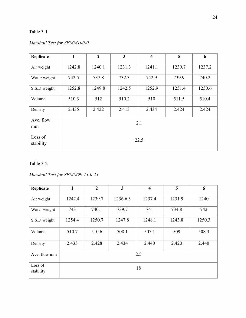
Marshall test was conducted, and the data of stability and flow were observed. Figure 3-3 shows
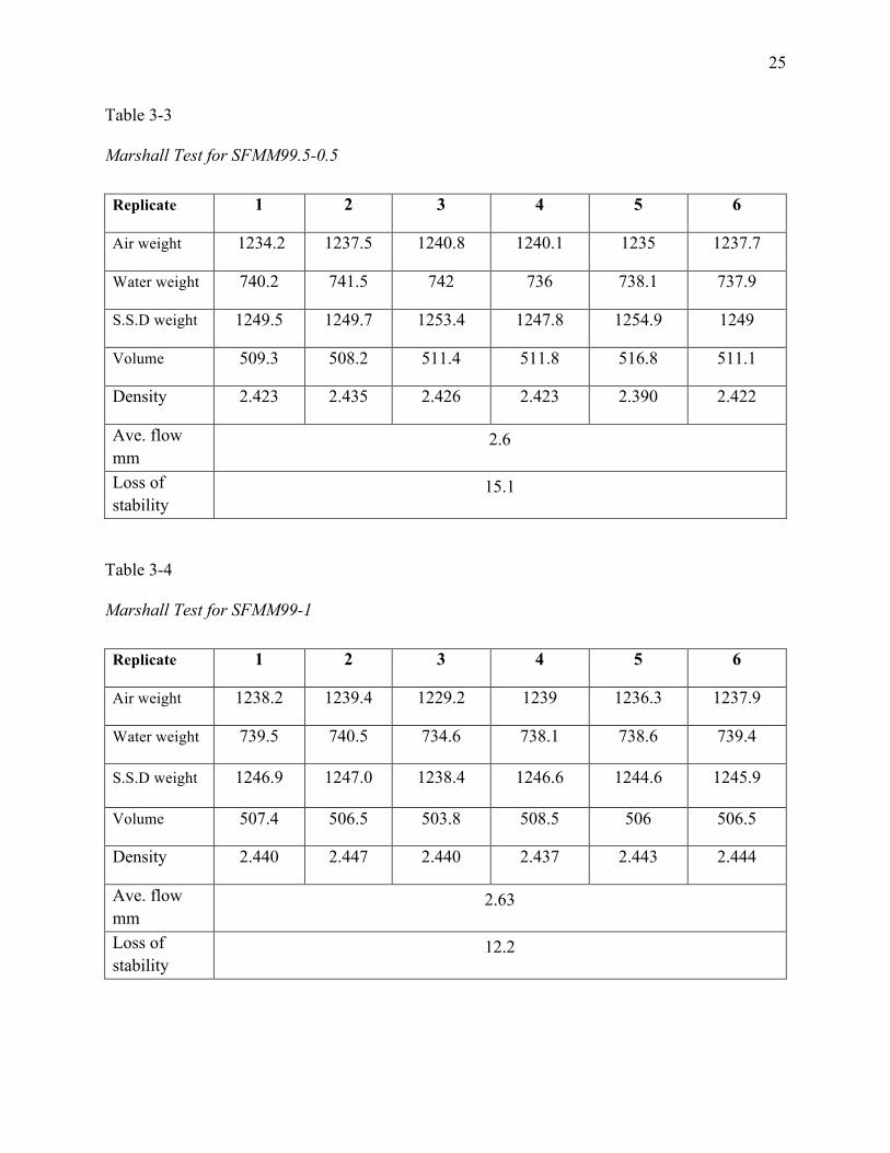
the Marshall test equipment. Table 3-1 shows the air, water ,and S.S.D weight as well as the
Marshal reading of the flow and stability for the mixture sample SFMM100-0. The SFMM refers
to Silica Fume Modified Mixture. The 100 is the percentage of asphalt mixture while the 0 is the
percentage of silica fume. Tables 3-2, 3-3, and 3-4 show the data of samples that contain 0.25%,
0.5%, and 1% of silica fume, respectively.
22
Figure 3-1. Mix Design Gradation
Figure 3-2. Asphalt Mixture Sample Replicates
23
Figure 3-3. Marshall Test
24
Table 3-1
Marshall Test for SFMM100-0
Replicate 1 2 3 4 5 6
Air weight 1242.8 1240.1 1231.3 1241.1 1239.7 1237.2
Water weight 742.5 737.8 732.3 742.9 739.9 740.2
S.S.D weight 1252.8 1249.8 1242.5 1252.9 1251.4 1250.6
Volume 510.3 512 510.2 510 511.5 510.4
Density 2.435 2.422 2.413 2.434 2.424 2.424
Ave. flow mm
2.1
Loss of stability
22.5
Table 3-2
Marshall Test for SFMM99.75-0.25
Replicate 1 2 3 4 5 6
Air weight 1242.4 1239.7 1236.6.3 1237.4 1231.9 1240
Water weight 743 740.1 739.7 741 734.8 742
S.S.D weight 1254.4 1250.7 1247.8 1248.1 1243.8 1250.3
Volume 510.7 510.6 508.1 507.1 509 508.3
Density 2.433 2.428 2.434 2.440 2.420 2.440
Ave. flow mm 2.5
Loss of stability
18
25
Table 3-3
Marshall Test for SFMM99.5-0.5
Replicate 1 2 3 4 5 6
Air weight 1234.2 1237.5 1240.8 1240.1 1235 1237.7
Water weight 740.2 741.5 742 736 738.1 737.9
S.S.D weight 1249.5 1249.7 1253.4 1247.8 1254.9 1249
Volume 509.3 508.2 511.4 511.8 516.8 511.1
Density 2.423 2.435 2.426 2.423 2.390 2.422
Ave. flow mm
2.6
Loss of stability
15.1
Table 3-4
Marshall Test for SFMM99-1
Replicate 1 2 3 4 5 6
Air weight 1238.2 1239.4 1229.2 1239 1236.3 1237.9
Water weight 739.5 740.5 734.6 738.1 738.6 739.4
S.S.D weight 1246.9 1247.0 1238.4 1246.6 1244.6 1245.9
Volume 507.4 506.5 503.8 508.5 506 506.5
Density 2.440 2.447 2.440 2.437 2.443 2.444
Ave. flow mm
2.63
Loss of stability
12.2
26
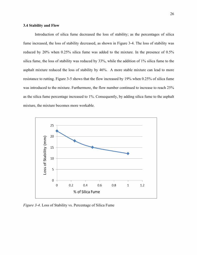
3.4 Stability and Flow
Introduction of silica fume decreased the loss of stability; as the percentages of silica
fume increased, the loss of stability decreased, as shown in Figure 3-4. The loss of stability was
reduced by 20% when 0.25% silica fume was added to the mixture. In the presence of 0.5%
silica fume, the loss of stability was reduced by 33%, while the addition of 1% silica fume to the
asphalt mixture reduced the loss of stability by 46%. A more stable mixture can lead to more
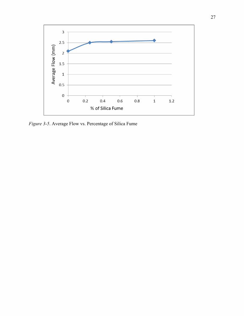
resistance to rutting. Figure 3-5 shows that the flow increased by 19% when 0.25% of silica fume
was introduced to the mixture. Furthermore, the flow number continued to increase to reach 25%
as the silica fume percentage increased to 1%. Consequently, by adding silica fume to the asphalt
mixture, the mixture becomes more workable.
Figure 3-4. Loss of Stability vs. Percentage of Silica Fume
27
Figure 3-5. Average Flow vs. Percentage of Silica Fume
28
CHAPTER 4
Methodology
In this chapter, asphalt binder PG 64-22 and silica fume are characterized.
4.1 Materials and Methods
The test materials used in this study were asphalt binder penetration grade PG 64-22 and
industrial waste silica fume. The silica fume concentrations in asphalt binder PG 64-22 were
selected to be 2%, 4%, and 8%, for both aged and non-aged samples.
4.1.1 Asphalt binders
The base binders for this study were penetration grade PG 64-22. Asphalt binder PG 64-
22 is commonly used in North Carolina.
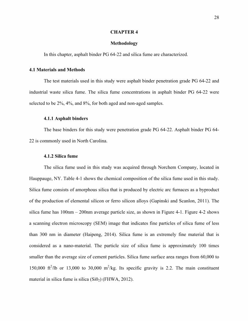
4.1.2 Silica fume
The silica fume used in this study was acquired through Norchem Company, located in
Hauppauge, NY. Table 4-1 shows the chemical composition of the silica fume used in this study.
Silica fume consists of amorphous silica that is produced by electric arc furnaces as a byproduct
of the production of elemental silicon or ferro silicon alloys (Gapinski and Scanlon, 2011). The
silica fume has 100nm – 200nm average particle size, as shown in Figure 4-1. Figure 4-2 shows
a scanning electron microscopy (SEM) image that indicates fine particles of silica fume of less
than 300 nm in diameter (Haipeng, 2014). Silica fume is an extremely fine material that is
considered as a nano-material. The particle size of silica fume is approximately 100 times
smaller than the average size of cement particles. Silica fume surface area ranges from 60,000 to
150,000 ft2/lb or 13,000 to 30,000 m2/kg. Its specific gravity is 2.2. The main constituent
material in silica fume is silica (Si02) (FHWA, 2012).
29
Table 4-1
Chemical Composition of Silica Fume
Chemical Composition % Chemical Composition %
Silicon Dioxide (SiO2) 90.26 Sodium Oxide (Na2O) 0.60
Aluminum Oxide (Al2O3) 0.13 Potassium Oxide (K2O) 1.34
Iron Oxide (Fe2O3) 2.46 Sulfur trioxide (SO3) 0.29
Calcium Oxide (CaO) 0.29 Others 0.26
Magnesium Oxide (MgO) 1.57 Loss on ignition 2.80
Figure 4-1. Silica Fume Particle Size Distribution
30
Figure 4-2. Silica Fume Particle Shape (Haipeng, 2014)
4.2 Viscosity Measurement
The rotational viscometer (RV) tests were conducted utilizing a Brookfield DV-III Ultra
viscometer equipped with thermosel to control temperature. The basic RV test measures torque
required to maintain a constant rotational speed of a specified spindle (in this study, spindle
SC27 was used) submerged in liquid asphalt at a constant temperature. The data is then used to
calculate viscosity from a measured torque. The viscosity of non-aged samples in the presence of
various amounts of silica fume (2%, 4%, and 8%) was measured by viscometer, following the
ASTM D4402 specification. Viscosity was measured at four different temperatures (105˚C,
120˚C, 135˚C, 150˚C), and six different speeds (5, 10, 20, 25, 50, and 75 RPM). At each
temperature, the reading was recorded after every 30 minutes.
31
4.3 Fourier Transform Infrared Spectroscopy (FTIR)
FTIR analysis was used to characterize silica-fume-modified asphalts. An FTIR
spectrometer, Shimadzu 1.30(2005) single reflection zinc selenide prism, was used in
transmission mode. In wave-numbers ranging from 4000/cm to 500/cm, the test was conducted
to get the spectra of asphalt samples. The prism was cleaned with methylene chloride. The
frequencies of IR radiation ("peaks" or "signals") could be linked directly to the bond type. Each
bond vibrates in different motions (stretching or bending); individual bonds may absorb different
IR frequencies. Stretching absorptions usually produce stronger peaks than bending, however,
the weak absorptions can be useful in differentiating similar types of bonds (e.g. aromatic
substitution). Table 4-2 is an example of some of the bonds and related absorption.
32
Table 4-2
Description of IR Absorptions (TutorVista, 2013)
Bond Compound Type Frequency Range, cm-1
C-H
Alkanes 2960-2850 (s) stretch
CH; Umbrella Deformation 1470-1350 (v) scissoring and bending
1380 (m-w) - Doublet - isopropyl, t-butyl
C-H Alkanes 3080-3020 (m) stretch 1000-675 (s) bend
C-H
Aromatic Rings 3100-3000 (m) stretch Phenyl Ring Substitution Bands
870-675 (s) bend
Phenyl Ring Substitution Overtones
2000-1600 (w) - fingerprint region
C-H Alkanes 3333-3267 (s) stretch 700-610 (b) bend
C=C Alkenes 1680-1640 (m,w) stretch C°C Alkynes 2260-2100 (w,sh) stretch C=C Aromatic Rings 1600, 1500 (w) stretch
C-O Alcohols, Ethers, Caroxylic acids, Esters
1260-1000 (s) stretch
C=O Aldehydes, Ketones, Carboxylic acids, Esters
1760-1670 (s) stretch
O-H
Monomeric -- Alcohols, Phenol
3640-3160 (s,br) stretch
Hydrogen-bonded -- Alcohols, Phenols
3600-3200 (b) stretch
Carboxylic acids 3000-2500 (b) stretch
N-H Amines 3500-3300 (m) stretch 1650-1580 (m) bend
C-N Amines 1340-1020 (m) bend C°N Nitriles 2260-2220 (v) stretch
NO2 Nitro Compounds 1660-1500 (s) asymmetrical stretch 1390-1260 (s) symmetrical stretch
33
4.4 Aging Procedure
Short-term laboratory aging of the binders was performed using a Rolling Thin Film
Oven (RTFO) procedure. The RTFO procedure was executed in accordance with ASTM D2872-
13.
4.5 X-Ray Diffraction Test
XRD is a significant technique to examine the exfoliation of nano-particles in asphalt
binders. This test is used to demonstrate a material’s polycrystalline structure. It identifies
components in a sample by search/match procedure. This tool is used to identify the atoms and
molecular structure in the crystal. From the density of the electron produced by the
crystallographer, the position of the atoms can be calculated, as well as the chemical bonds.
(Barbara and Clark, 2013). All samples were placed in an oven at 150ºC until a homogeneous
liquid phase was attained. A small portion was then placed in a silver sample holder (eight mm
each in diameter). Each specimen was carefully examined to identify any bulge or irregularity on
the surface. The sample-A glass plate was used to trim any excess sample off the top of the
specimen. The sample holder was then placed on a flat surface, and the samples were loaded
onto the tray. The specimens were left to cure at room temperature before running the test. After
curing, the samples were placed on an eight-shelf holster and set in the correct position for
testing to take place.
4.6 Mixture Design
PG 64-22 was placed in a typical oven at 200˚C until it reaches a homogeneous liquid
phase. There are twelve mixtures designed in this research, 250 grams of each mixture. Table 4-3
indicates the experiment mixture design of the binder level study. 8 Samples were conducted
using silica fume modified binder. ASFMA is an abbreviation for Aged Silica-Fume-Modified
34
Asphalt; NSFMA is an abbreviation for Non-aged Silica-Fume-Modified Asphalt. The numbers
appended to ASFMA or NSFMA indicate the percentage of asphalt binder followed by the
percentage of silica fume.
Table 4-3
Experiment Mixture Design
Aged (RTFO) Non-Aged Control
(PG 64-22) Silica Fume Control
(PG 64-22) Silica Fume
ASFMA100-0 100% 0%
ASFMA98-2 98% 2%
ASFMA96-4 96% 4%
ASFMA92-8 92% 8%
NSFMA100-0 100% 0%
NSFMA98-2 98% 2%
NSFMA96-4 96% 4%
NSFMA92-8 92% 8%
4.6.1 Silica fume
The mixture including 2% silica fume contains 245 grams of PG 64-22. These 245 grams
of PG 64-22 were placed on a heating plate. The heating plate was set to 200˚C, where the
blending took place. A drill with a mixing attachment was used to blend. Blending time was 30
minutes, where 5 grams of silica fume (2%) was poured into the PG 64-22 (245 grams) asphalt
binder momentarily. This procedure was then repeated for the remaining two mixture designs.
For 4% silica fume, 10 grams of silica fume was gradually added to 240 grams of PG 64-22
asphalt binder over a heating plate at 200˚C. For 8% silica fume, 20 grams of silica fume was
gradually added to 230 grams of PG 64-22 asphalt binder over a heating plate at 200˚C.
35
4.7 Sample Preparation
4.7.1 Rotational viscosity test
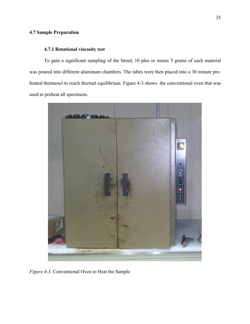
To gain a significant sampling of the blend, 10 plus or minus 5 grams of each material
was poured into different aluminum chambers. The tubes were then placed into a 30 minute pre-
heated thermosel to reach thermal equilibrium. Figure 4-3 shows the conventional oven that was
used to preheat all specimens.
Figure 4-3. Conventional Oven to Heat the Sample
36
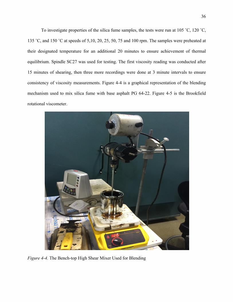
To investigate properties of the silica fume samples, the tests were run at 105 ˚C, 120 ˚C,
135 ˚C, and 150 ˚C at speeds of 5,10, 20, 25, 50, 75 and 100 rpm. The samples were preheated at
their designated temperature for an additional 20 minutes to ensure achievement of thermal
equilibrium. Spindle SC27 was used for testing. The first viscosity reading was conducted after
15 minutes of shearing, then three more recordings were done at 3 minute intervals to ensure
consistency of viscosity measurements. Figure 4-4 is a graphical representation of the blending
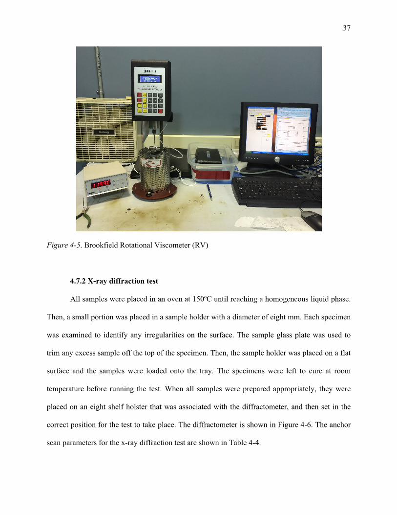
mechanism used to mix silica fume with base asphalt PG 64-22. Figure 4-5 is the Brookfield
rotational viscometer.
Figure 4-4. The Bench-top High Shear Mixer Used for Blending
37
Figure 4-5. Brookfield Rotational Viscometer (RV)
4.7.2 X-ray diffraction test
All samples were placed in an oven at 150ºC until reaching a homogeneous liquid phase.
Then, a small portion was placed in a sample holder with a diameter of eight mm. Each specimen
was examined to identify any irregularities on the surface. The sample glass plate was used to
trim any excess sample off the top of the specimen. Then, the sample holder was placed on a flat
surface and the samples were loaded onto the tray. The specimens were left to cure at room
temperature before running the test. When all samples were prepared appropriately, they were
placed on an eight shelf holster that was associated with the diffractometer, and then set in the
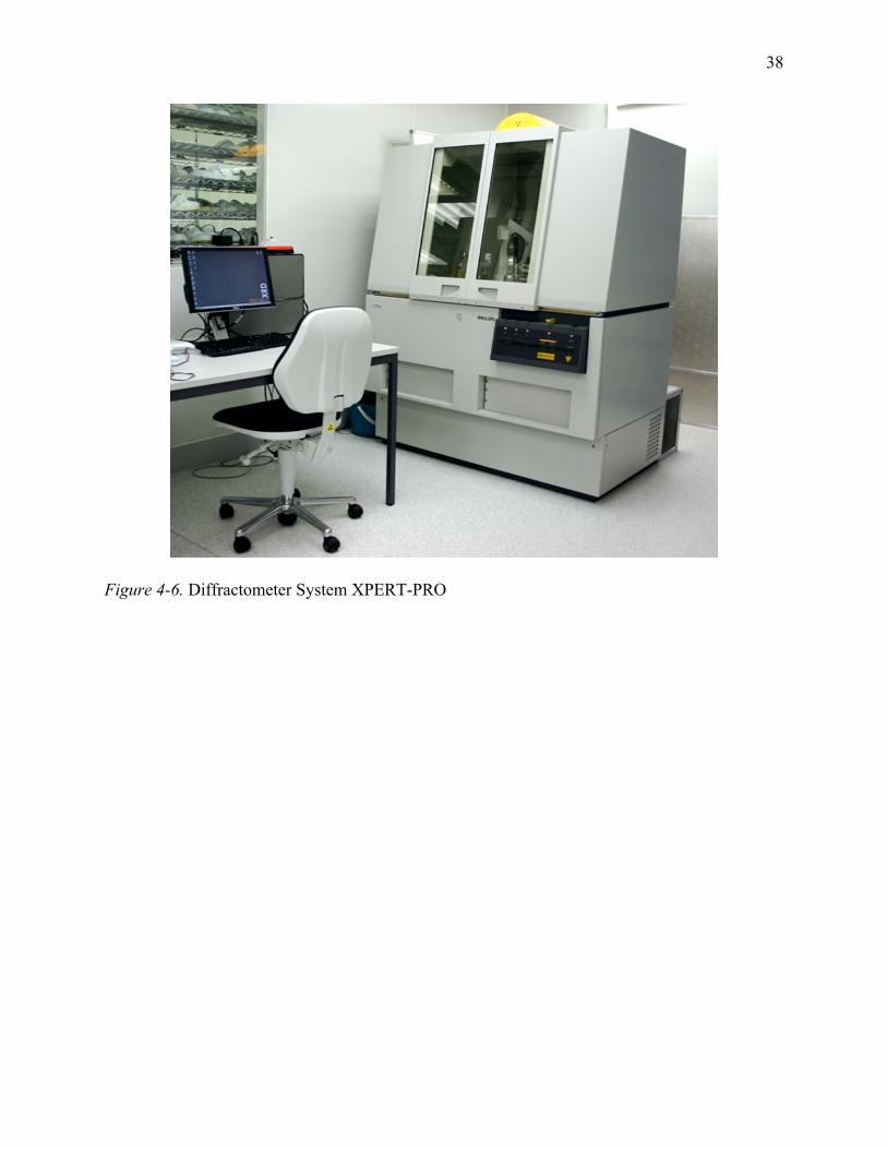
correct position for the test to take place. The diffractometer is shown in Figure 4-6. The anchor
scan parameters for the x-ray diffraction test are shown in Table 4-4.
38
Figure 4-6. Diffractometer System XPERT-PRO
39
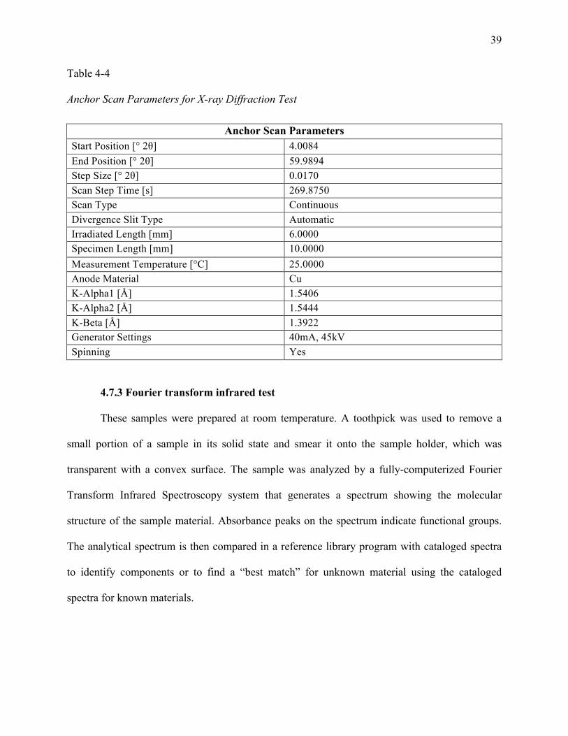
Table 4-4
Anchor Scan Parameters for X-ray Diffraction Test
Anchor Scan Parameters Start Position [° 2θ] 4.0084 End Position [° 2θ] 59.9894 Step Size [° 2θ] 0.0170 Scan Step Time [s] 269.8750 Scan Type Continuous Divergence Slit Type Automatic Irradiated Length [mm] 6.0000 Specimen Length [mm] 10.0000 Measurement Temperature [°C] 25.0000 Anode Material Cu K-Alpha1 [Å] 1.5406 K-Alpha2 [Å] 1.5444 K-Beta [Å] 1.3922 Generator Settings 40mA, 45kV Spinning Yes
4.7.3 Fourier transform infrared test
These samples were prepared at room temperature. A toothpick was used to remove a
small portion of a sample in its solid state and smear it onto the sample holder, which was
transparent with a convex surface. The sample was analyzed by a fully-computerized Fourier
Transform Infrared Spectroscopy system that generates a spectrum showing the molecular
structure of the sample material. Absorbance peaks on the spectrum indicate functional groups.
The analytical spectrum is then compared in a reference library program with cataloged spectra
to identify components or to find a “best match” for unknown material using the cataloged
spectra for known materials.
40
CHAPTER 5
Results
All analysis and results from this study are discussed in this chapter. Graphs and
procedures are used to help illustrate each specimen as it is compared with other specimens.
Tests were run at the North Carolina A&T State University Civil Engineering Lab and the
Laboratory for Atomistic and Molecular Mechanics (LAMM) as well as the Center for Materials
Science and Engineering at MIT (CMSE) lab.
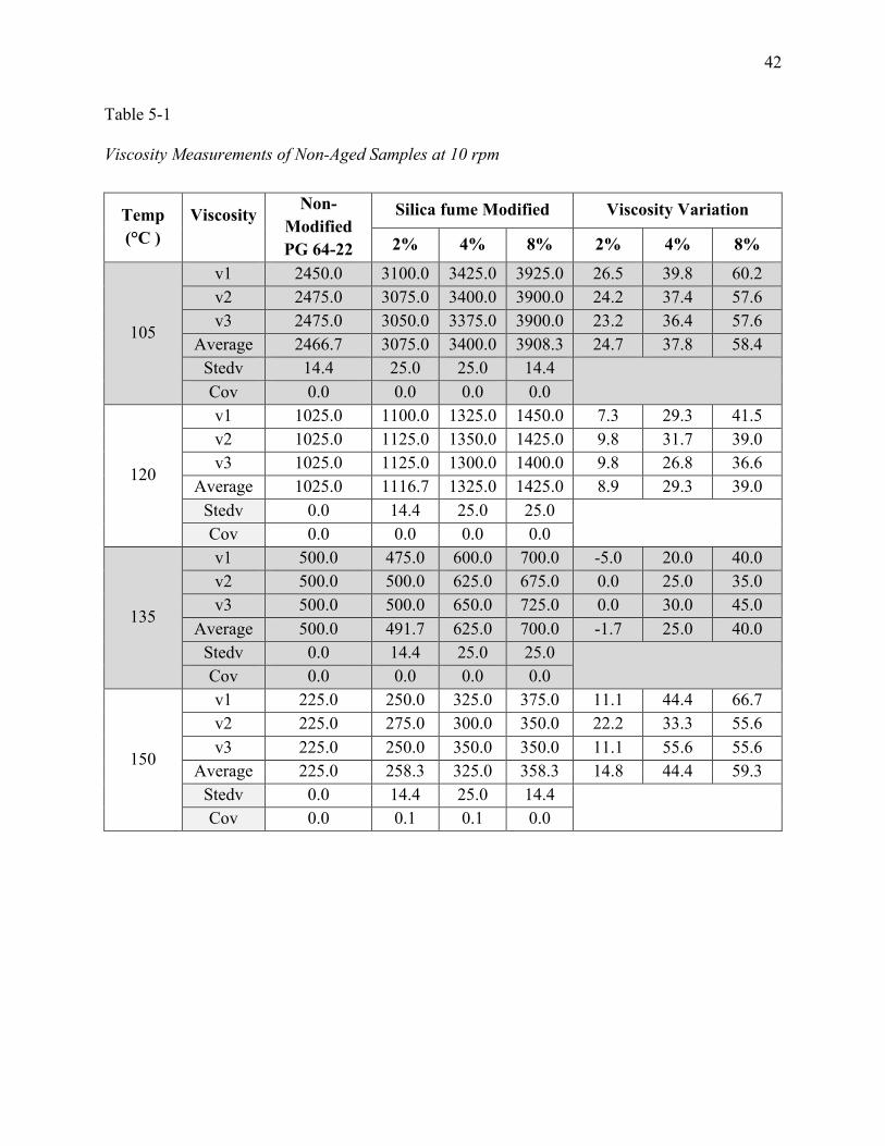
5.1 Viscosity Measurement Before Aging
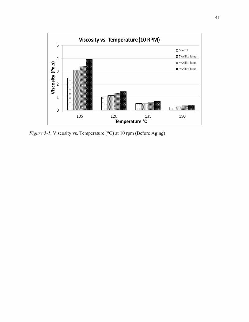
At a shear rate of 10 rpm, Figure 5-1 shows that at each temperature, the viscosity
measurement results indicate a significant increase of viscosity due to the addition of silica fume.
At 105°C, the viscosity increased by 25% when 2% silica fume was added to the control asphalt
binder PG 64-22. The viscosity increased by 38% and 58% when silica fume was increased 4%
and 8%, respectively. At 120°C, the presence of 8% silica fume in modified asphalt binder
resulted in a 40% increase in the viscosity. At 135°C, which is the standard temperature, a 2%
decrease in viscosity was found when 2% of silica fume was introduced to the control asphalt
binder. When 4% silica fume was added to the control binder, the viscosity increased by 25%,
while adding 8% silica fume increased the viscosity by 40%. At a high temperature of 150°C, the
viscosity increased by 15%, 40%, and 59% when 2%, 4% and 8% silica fume was added,
respectively. The data is shown in Table 5-1.
41
Figure 5-1. Viscosity vs. Temperature (°C) at 10 rpm (Before Aging)
42
Table 5-1
Viscosity Measurements of Non-Aged Samples at 10 rpm
Temp (°C )
Viscosity
Non-Modified PG 64-22
Silica fume Modified Viscosity Variation
2% 4% 8% 2% 4% 8%
105
v1 2450.0 3100.0 3425.0 3925.0 26.5 39.8 60.2 v2 2475.0 3075.0 3400.0 3900.0 24.2 37.4 57.6 v3 2475.0 3050.0 3375.0 3900.0 23.2 36.4 57.6
Average 2466.7 3075.0 3400.0 3908.3 24.7 37.8 58.4 Stedv 14.4 25.0 25.0 14.4
Cov 0.0 0.0 0.0 0.0
120
v1 1025.0 1100.0 1325.0 1450.0 7.3 29.3 41.5 v2 1025.0 1125.0 1350.0 1425.0 9.8 31.7 39.0 v3 1025.0 1125.0 1300.0 1400.0 9.8 26.8 36.6
Average 1025.0 1116.7 1325.0 1425.0 8.9 29.3 39.0 Stedv 0.0 14.4 25.0 25.0
Cov 0.0 0.0 0.0 0.0
135
v1 500.0 475.0 600.0 700.0 -5.0 20.0 40.0 v2 500.0 500.0 625.0 675.0 0.0 25.0 35.0 v3 500.0 500.0 650.0 725.0 0.0 30.0 45.0
Average 500.0 491.7 625.0 700.0 -1.7 25.0 40.0 Stedv 0.0 14.4 25.0 25.0
Cov 0.0 0.0 0.0 0.0
150
v1 225.0 250.0 325.0 375.0 11.1 44.4 66.7 v2 225.0 275.0 300.0 350.0 22.2 33.3 55.6 v3 225.0 250.0 350.0 350.0 11.1 55.6 55.6
Average 225.0 258.3 325.0 358.3 14.8 44.4 59.3 Stedv 0.0 14.4 25.0 14.4
Cov 0.0 0.1 0.1 0.0
43
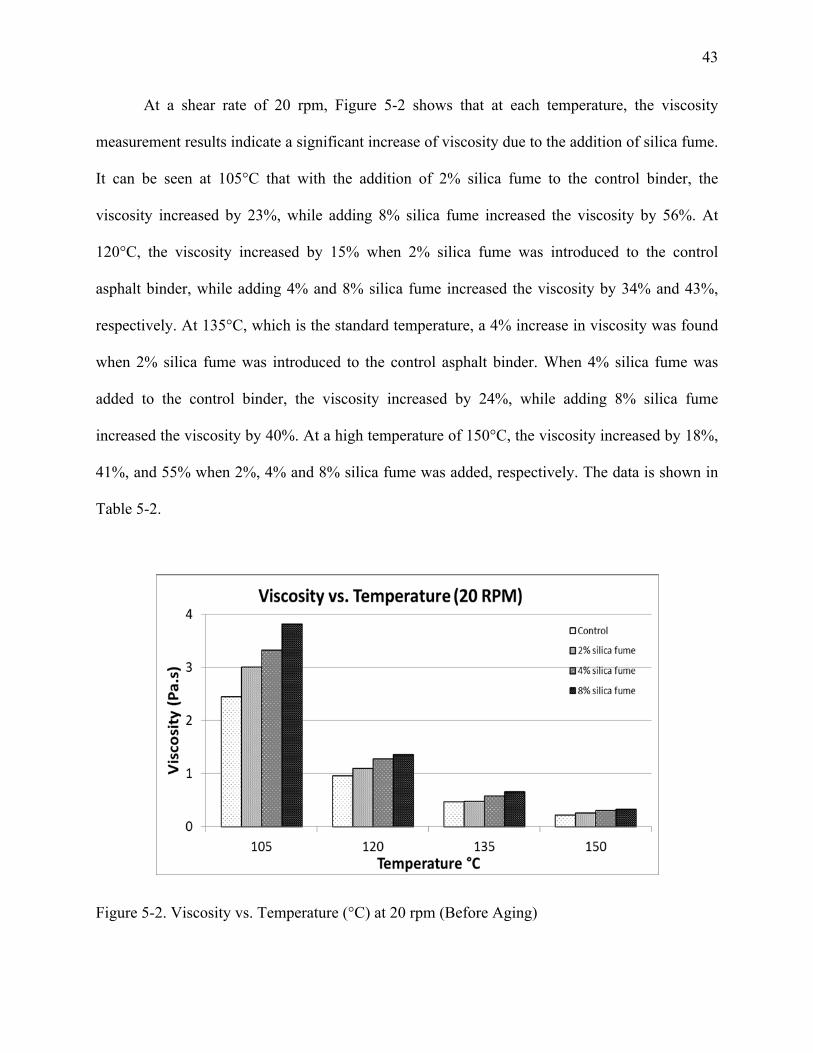
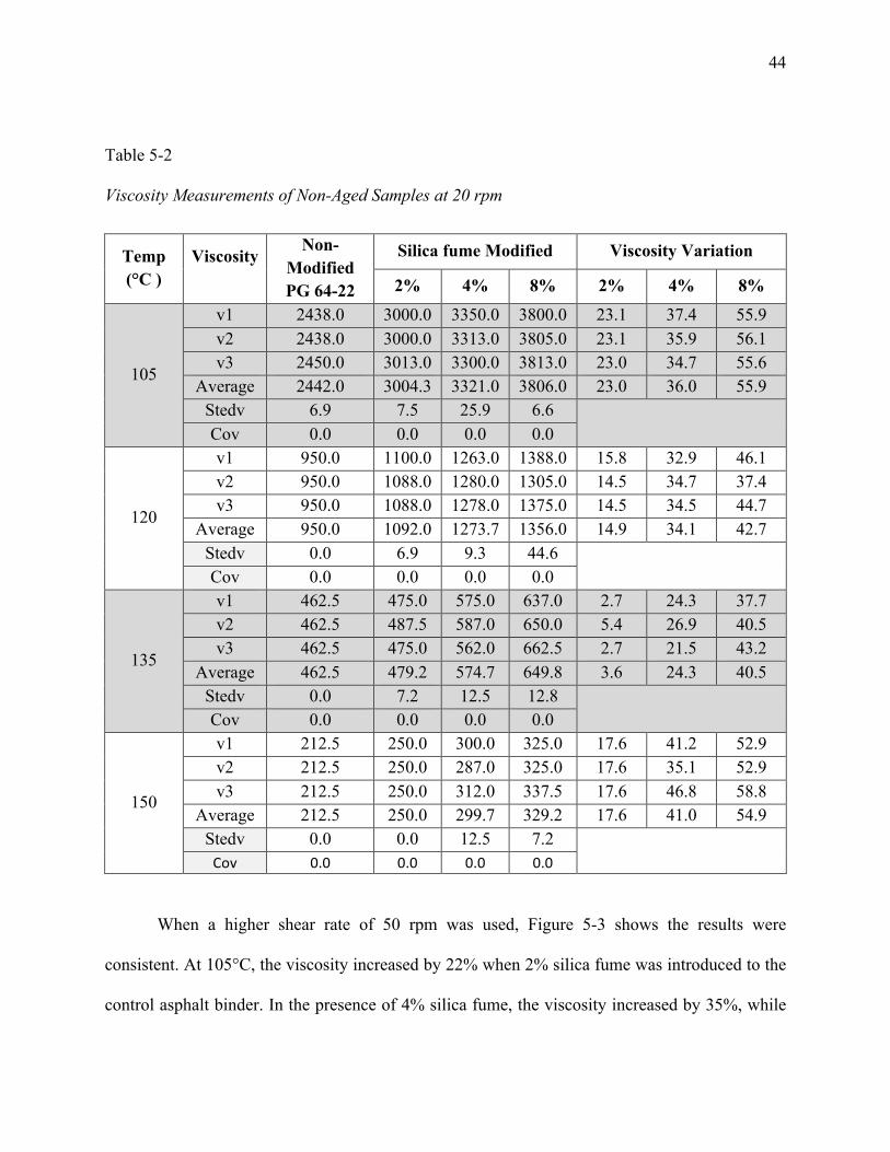
At a shear rate of 20 rpm, Figure 5-2 shows that at each temperature, the viscosity
measurement results indicate a significant increase of viscosity due to the addition of silica fume.
It can be seen at 105°C that with the addition of 2% silica fume to the control binder, the
viscosity increased by 23%, while adding 8% silica fume increased the viscosity by 56%. At
120°C, the viscosity increased by 15% when 2% silica fume was introduced to the control
asphalt binder, while adding 4% and 8% silica fume increased the viscosity by 34% and 43%,
respectively. At 135°C, which is the standard temperature, a 4% increase in viscosity was found
when 2% silica fume was introduced to the control asphalt binder. When 4% silica fume was
added to the control binder, the viscosity increased by 24%, while adding 8% silica fume
increased the viscosity by 40%. At a high temperature of 150°C, the viscosity increased by 18%,
41%, and 55% when 2%, 4% and 8% silica fume was added, respectively. The data is shown in
Table 5-2.
Figure 5-2. Viscosity vs. Temperature (°C) at 20 rpm (Before Aging)
44
Table 5-2
Viscosity Measurements of Non-Aged Samples at 20 rpm
Temp (°C )
Viscosity
Non-Modified PG 64-22
Silica fume Modified Viscosity Variation
2% 4% 8% 2% 4% 8%
105
v1 2438.0 3000.0 3350.0 3800.0 23.1 37.4 55.9 v2 2438.0 3000.0 3313.0 3805.0 23.1 35.9 56.1 v3 2450.0 3013.0 3300.0 3813.0 23.0 34.7 55.6
Average 2442.0 3004.3 3321.0 3806.0 23.0 36.0 55.9 Stedv 6.9 7.5 25.9 6.6
Cov 0.0 0.0 0.0 0.0
120
v1 950.0 1100.0 1263.0 1388.0 15.8 32.9 46.1 v2 950.0 1088.0 1280.0 1305.0 14.5 34.7 37.4 v3 950.0 1088.0 1278.0 1375.0 14.5 34.5 44.7
Average 950.0 1092.0 1273.7 1356.0 14.9 34.1 42.7 Stedv 0.0 6.9 9.3 44.6
Cov 0.0 0.0 0.0 0.0
135
v1 462.5 475.0 575.0 637.0 2.7 24.3 37.7 v2 462.5 487.5 587.0 650.0 5.4 26.9 40.5 v3 462.5 475.0 562.0 662.5 2.7 21.5 43.2
Average 462.5 479.2 574.7 649.8 3.6 24.3 40.5 Stedv 0.0 7.2 12.5 12.8
Cov 0.0 0.0 0.0 0.0
150
v1 212.5 250.0 300.0 325.0 17.6 41.2 52.9 v2 212.5 250.0 287.0 325.0 17.6 35.1 52.9 v3 212.5 250.0 312.0 337.5 17.6 46.8 58.8
Average 212.5 250.0 299.7 329.2 17.6 41.0 54.9 Stedv 0.0 0.0 12.5 7.2 Cov 0.0 0.0 0.0 0.0
When a higher shear rate of 50 rpm was used, Figure 5-3 shows the results were
consistent. At 105°C, the viscosity increased by 22% when 2% silica fume was introduced to the
control asphalt binder. In the presence of 4% silica fume, the viscosity increased by 35%, while
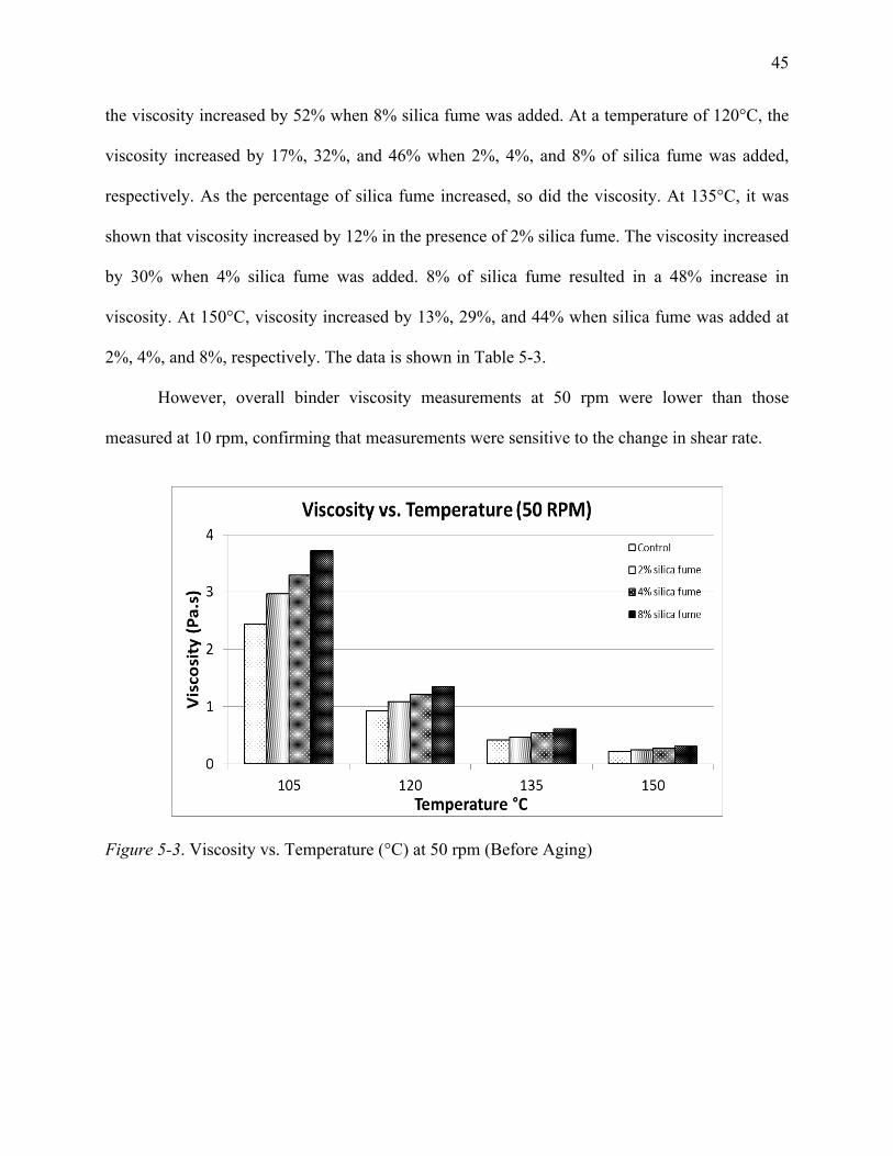
45
the viscosity increased by 52% when 8% silica fume was added. At a temperature of 120°C, the
viscosity increased by 17%, 32%, and 46% when 2%, 4%, and 8% of silica fume was added,
respectively. As the percentage of silica fume increased, so did the viscosity. At 135°C, it was
shown that viscosity increased by 12% in the presence of 2% silica fume. The viscosity increased
by 30% when 4% silica fume was added. 8% of silica fume resulted in a 48% increase in
viscosity. At 150°C, viscosity increased by 13%, 29%, and 44% when silica fume was added at
2%, 4%, and 8%, respectively. The data is shown in Table 5-3.
However, overall binder viscosity measurements at 50 rpm were lower than those
measured at 10 rpm, confirming that measurements were sensitive to the change in shear rate.
Figure 5-3. Viscosity vs. Temperature (°C) at 50 rpm (Before Aging)
46
Table 5-3
Viscosity Measurements of Non-Aged Samples at 50 rpm
Temp (°C )
Viscosity
Non-Modified PG 64-22
Silica fume Modified Viscosity Variation
2% 4% 8% 2% 4% 8%
105
v1 2435.0 2965.0 3290.0 3720.0 21.8 35.1 52.8 v2 2430.0 2960.0 3285.0 3700.0 21.8 35.2 52.3 v3 2440.0 2960.0 3290.0 3715.0 21.3 34.8 52.3
Average 2435.0 2961.7 3288.3 3711.7 21.6 35.0 52.4 Stedv 5.0 2.9 2.9 10.4
Cov 0.0 0.0 0.0 0.0
120
v1 920.0 1075.0 1215.0 1345.0 16.8 32.1 46.2 v2 920.0 1080.0 1220.0 1340.0 17.4 32.6 45.7 v3 920.0 1080.0 1210.0 1350.0 17.4 31.5 46.7
Average 920.0 1078.3 1215.0 1345.0 17.2 32.1 46.2 Stedv 0.0 2.9 5.0 5.0
Cov 0.0 0.0 0.0 0.0
135
v1 415.0 465.0 535.0 605.0 12.0 28.9 45.8 v2 415.0 470.0 540.0 612.0 13.3 30.1 47.5 v3 415.0 465.0 540.0 610.0 12.0 30.1 47.0
Average 415.0 466.7 538.3 609.0 12.4 29.7 46.7 Stedv 0.0 2.9 2.9 3.6
Cov 0.0 0.0 0.0 0.0
150
v1 210.0 235.0 270.0 300.0 11.9 28.6 42.9 v2 210.0 240.0 270.0 300.0 14.3 28.6 42.9 v3 210.0 240.0 275.0 305.0 14.3 31.0 45.2
Average 210.0 238.3 271.7 301.7 13.5 29.4 43.7 Stedv 0.0 2.9 2.9 2.9
Cov 0.0 0.0 0.0 0.0
5.2 Rolling Thin-Film Oven (RTFO)
The Rolling Thin-Film Oven (RTFO), shown in Figure 5-4, represents short-term
oxidation aging. It is used to simulate the aging process in the field in terms of air and
47
temperature. The RTFO procedure was executed in accordance with ASTM D2872-13. To start
the method of short-term aging using the RTFO, the following procedure was used. The samples
of control asphalt binder, 2%, 4%, and 8% silica-fume-modified binder were pre-heated for 4
hours. Then, 35.5g of each asphalt sample was poured into each glass bottle. After that, the
bottles were rotated and placed at room temperature to cool for 60 to 180 minutes. The bottles
were placed in a circular metal carriage in the RTFO oven carousel, shown in Figure 5-5. While
maintaining the oven temperature at 163°C and the airflow into the bottles at 4000 ml/min., the
carousel was rotated at 15 RPM for 85 minutes. As a result, the samples became aged in terms of
air and temperature.
Figure 5-4. Rolling Thin-Film Oven (RTFO)
48
Figure 5-5. Rotating Circular Metal Carriage
5.3 Viscosity Measurement after Aging
Figure 5-6 shows the rotational viscosity results of modified and non-modified specimens
after RTFO aging, when tested at 10 rpm. It can be seen at 105°C that with the addition of 2%
silica fume to the control binder, the viscosity decreased by 7%, while adding 8% silica fume
increased the viscosity by 21%. At 120°C, the viscosity decreased by 2% when 2% silica fume
was introduced to the control asphalt binder, while adding 4% and 8% silica fume increased the
viscosity by 7% and 21%, respectively. At 135°C, which is the standard temperature, a 7%
decrease in viscosity was found when 2% silica fume was introduced to the control asphalt
binder. When 4% silica fume was added to the control binder, the viscosity increased by 10%,
while adding 8% silica fume increased the viscosity by 27%. At a high temperature of 150°C, the
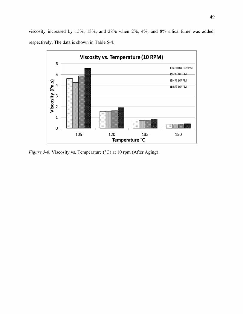
49
viscosity increased by 15%, 13%, and 28% when 2%, 4%, and 8% silica fume was added,
respectively. The data is shown in Table 5-4.
Figure 5-6. Viscosity vs. Temperature (°C) at 10 rpm (After Aging)
50
Table 5-4
Viscosity Measurements of Aged Samples at 10 rpm
Temp (°C )
Viscosity
Non-Modified PG 64-22
Silica fume Modified Viscosity Variation
2% 4% 8% 2% 4% 8%
105
v1 4650.0 4300.0 4875.0 5550.0 -7.5 4.8 19.4 v2 4600.0 4275.0 4900.0 5600.0 -7.1 6.5 21.7 v3 4600.0 4250.0 4875.0 5550.0 -7.6 6.0 20.7
Average 4616.7 4275.0 4883.3 5566.7 -7.4 5.8 20.6 Stedv 28.9 25.0 14.4 28.9
Cov 0.0 0.0 0.0 0.0
120
v1 1575.0 1550.0 1700.0 1950.0 -1.6 7.9 23.8 v2 1600.0 1550.0 1700.0 1900.0 -3.1 6.3 18.8 v3 1575.0 1550.0 1700.0 1900.0 -1.6 7.9 20.6
Average 1583.3 1550.0 1700.0 1916.7 -2.1 7.4 21.1 Stedv 14.4 0.0 0.0 28.9
Cov 0.0 0.0 0.0 0.0
135
v1 700.0 725.0 750.0 850.0 3.6 7.1 21.4 v2 675.0 750.0 750.0 875.0 11.1 11.1 29.6 v3 675.0 725.0 750.0 875.0 7.4 11.1 29.6
Average 683.3 733.3 750.0 866.7 7.3 9.8 26.8 Stedv 14.4 14.4 0.0 14.4
Cov 0.0 0.0 0.0 0.0
150
v1 325.0 375.0 375.0 425.0 15.4 15.4 30.8 v2 350.0 400.0 375.0 425.0 14.3 7.1 21.4 v3 325.0 375.0 375.0 425.0 15.4 15.4 30.8
Average 333.3 383.3 375.0 425.0 15.0 12.5 27.5 Stedv 14.4 14.4 0.0 0.0
Cov 0.0 0.0 0.0 0.0
Figure 5-7 shows the rotational viscosity results of modified and non-modified specimens
after RTFO aging, when tested at 20 rpm. At 105°C, viscosity decreased by 7% when 2% silica
fume was introduced to the control asphalt binder, PG 64-22. Viscosity increased by 6% and
20% when silica fume was added at 4% and 8%, respectively. At 120°C, the presence of 8%
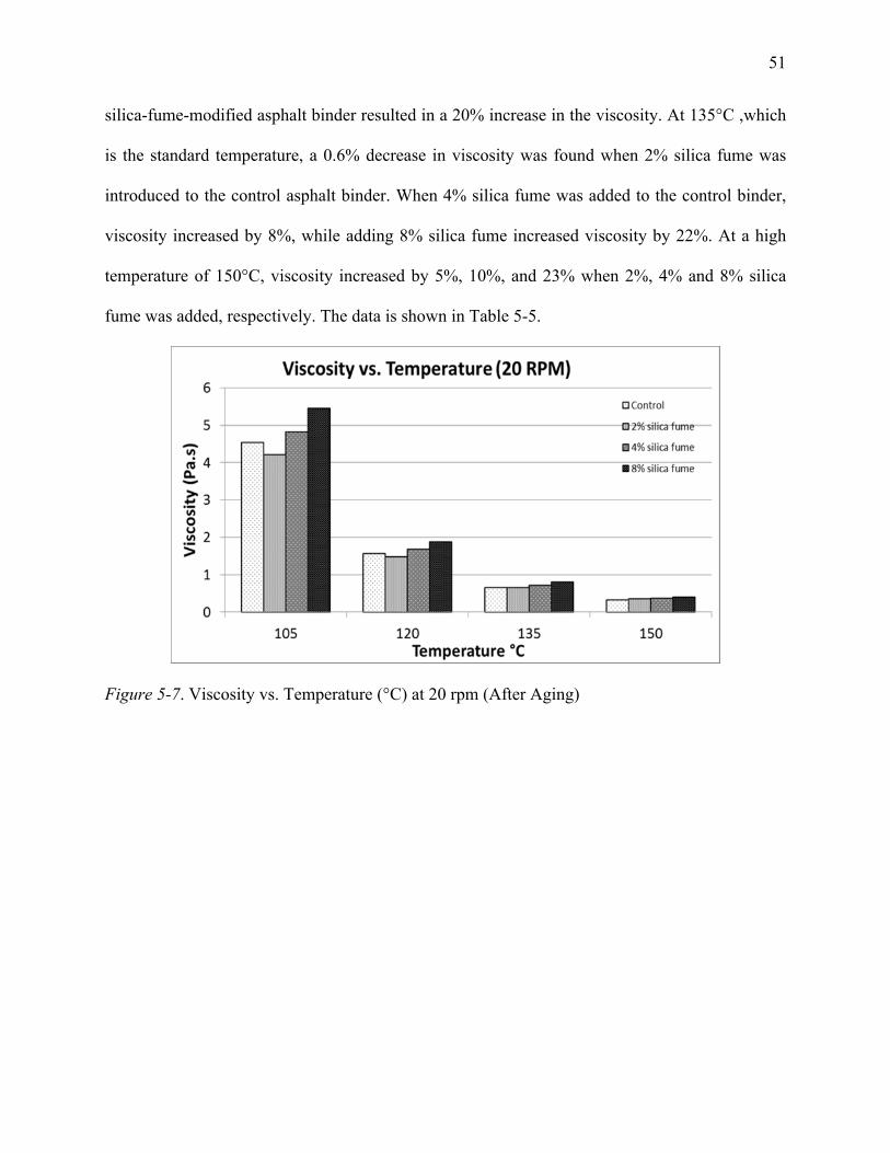
51
silica-fume-modified asphalt binder resulted in a 20% increase in the viscosity. At 135°C ,which
is the standard temperature, a 0.6% decrease in viscosity was found when 2% silica fume was
introduced to the control asphalt binder. When 4% silica fume was added to the control binder,
viscosity increased by 8%, while adding 8% silica fume increased viscosity by 22%. At a high
temperature of 150°C, viscosity increased by 5%, 10%, and 23% when 2%, 4% and 8% silica
fume was added, respectively. The data is shown in Table 5-5.
Figure 5-7. Viscosity vs. Temperature (°C) at 20 rpm (After Aging)
52
Table 5-5
Viscosity Measurements of Aged Samples at 20 rpm
Temp (°C )
Viscosity
Non-Modified PG 64-22
Silica fume Modified Viscosity Variation
2% 4% 8% 2% 4% 8%
105
v1 4550.0 4213.0 4838.0 5475.0 -7.4 6.3 20.3 v2 4550.0 4200.0 4825.0 5463.0 -7.7 6.0 20.1 v3 4550.0 4225.0 4825.0 5463.0 -7.1 6.0 20.1
Average 4550.0 4212.7 4829.3 5467.0 -7.4 6.1 20.2 Stedv 0.0 12.5 7.5 6.9
Cov 0.0 0.0 0.0 0.0
120
v1 1563.0 1475.0 1688.0 1880.0 -5.6 8.0 20.3 v2 1563.0 1488.0 1675.0 1875.0 -4.8 7.2 20.0 v3 1575.0 1463.0 1675.0 1875.0 -7.1 6.3 19.0
Average 1567.0 1475.3 1679.3 1876.7 -5.8 7.2 19.8 Stedv 6.9 12.5 7.5 2.9
Cov 0.0 0.0 0.0 0.0
135
v1 662.5 662.5 712.5 812.0 0.0 7.5 22.6 v2 650.0 650.0 712.5 800.0 0.0 9.6 23.1 v3 662.5 650.0 712.5 800.0 -1.9 7.5 20.8
Average 658.3 654.2 712.5 804.0 -0.6 8.2 22.1 Stedv 7.2 7.2 0.0 6.9
Cov 0.0 0.0 0.0 0.0
150
v1 325.0 350.0 362.0 400.0 7.7 11.4 23.1 v2 325.0 337.0 362.0 412.0 3.7 11.4 26.8 v3 337.5 350.0 362.0 400.0 3.7 7.3 18.5
Average 329.2 345.7 362.0 404.0 5.0 10.0 22.7 Stedv 7.2 7.5 0.0 6.9
Cov 0.0 0.0 0.0 0.0
Figure 5-8 shows the viscosity measurement after RTFO aging, when tested at 50 rpm. At
105°C, the viscosity decreased by 8% when 2% silica fume was introduced to the control asphalt
binder. In the presence of 4% silica fume, viscosity increased by 6%. At a temperature of 120°C,
viscosity decreased by 6% when 2% of silica fume was introduced to the control asphalt binder,
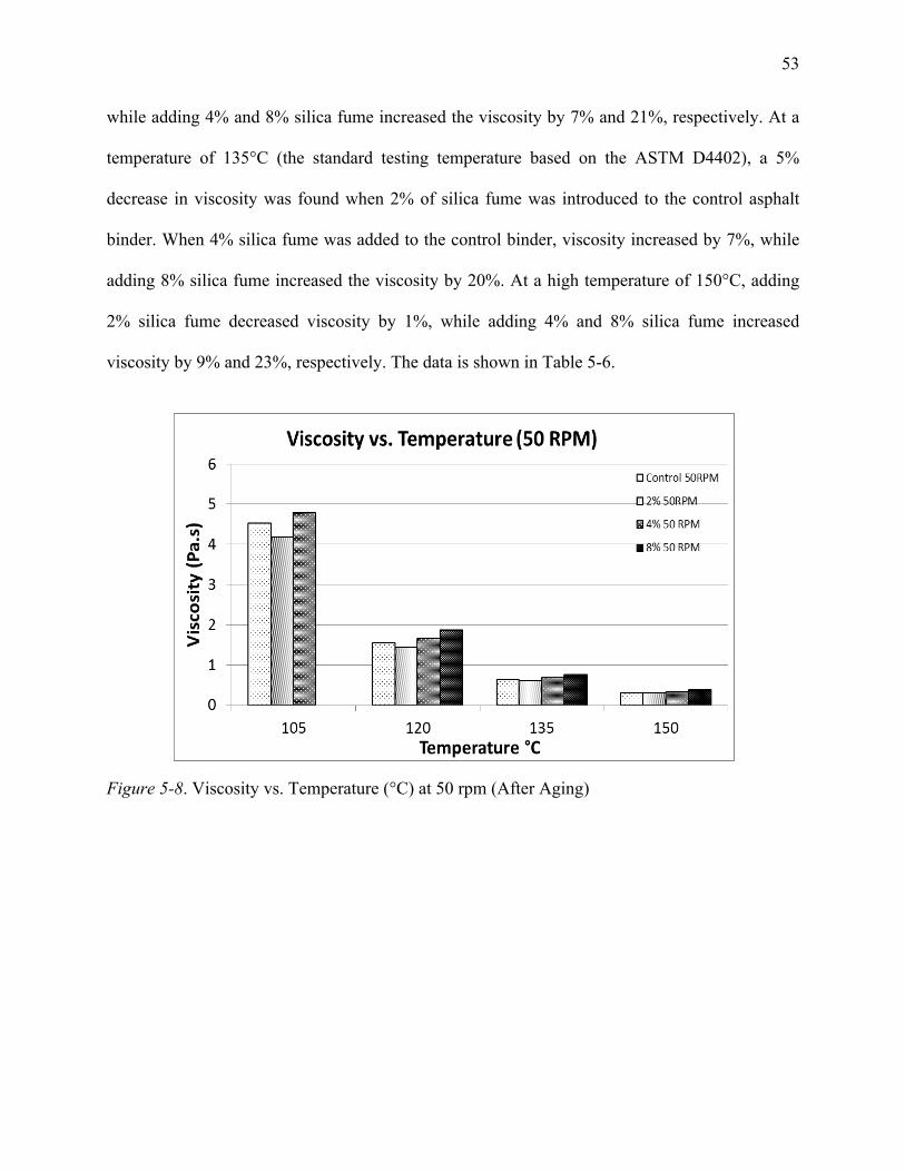
53
while adding 4% and 8% silica fume increased the viscosity by 7% and 21%, respectively. At a
temperature of 135°C (the standard testing temperature based on the ASTM D4402), a 5%
decrease in viscosity was found when 2% of silica fume was introduced to the control asphalt
binder. When 4% silica fume was added to the control binder, viscosity increased by 7%, while
adding 8% silica fume increased the viscosity by 20%. At a high temperature of 150°C, adding
2% silica fume decreased viscosity by 1%, while adding 4% and 8% silica fume increased
viscosity by 9% and 23%, respectively. The data is shown in Table 5-6.
Figure 5-8. Viscosity vs. Temperature (°C) at 50 rpm (After Aging)
54
Table 5-6
Viscosity Measurements of Aged Samples at 50 rpm
Temp (°C )
Viscosity
Non-Modified PG 64-22
Silica fume Modified Viscosity Variation
2% 4% 8% 2% 4% 8%
105
v1 4520.0 4175.0 4770.0 -- -7.6 5.5 -- v2 4520.0 4170.0 4785.0 -- -7.7 5.9 -- v3 4525.0 4175.0 4780.0 -- -7.7 5.6 --
Average 4521.7 4173.3 4778.3 -- -7.7 5.7 -- Stedv 2.9 2.9 7.6 --
Cov 0.0 0.0 0.0 --
120
v1 1550.0 1445.0 1655.0 1865.0 -6.8 6.8 20.3 v2 1540.0 1445.0 1655.0 1865.0 -6.2 7.5 21.1 v3 1540.0 1445.0 1650.0 1860.0 -6.2 7.1 20.8
Average 1543.3 1445.0 1653.3 1863.3 -6.4 7.1 20.7 Stedv 5.8 0.0 2.9 2.9
Cov 0.0 0.0 0.0 0.0
135
v1 640.0 610.0 685.0 765.0 -4.7 7.0 19.5 v2 635.0 605.0 685.0 770.0 -4.7 7.9 21.3 v3 640.0 605.0 685.0 760.0 -5.5 7.0 18.8
Average 638.3 606.7 685.0 765.0 -5.0 7.3 19.8 Stedv 2.9 2.9 0.0 5.0
Cov 0.0 0.0 0.0 0.0
150
v1 305.0 300.0 330.0 375.0 -1.6 8.2 23.0 v2 305.0 305.0 335.0 375.0 0.0 9.8 23.0 v3 305.0 300.0 330.0 375.0 -1.6 8.2 23.0
Average 305.0 301.7 331.7 375.0 -1.1 8.7 23.0 Stedv 0.0 2.9 2.9 0.0
Cov 0.0 0.0 0.0 0.0
5.4 Viscosity Aging Index
The viscosity aging index (VAI) is used to evaluate the extent of aging. It is calculated
from the viscosity of the samples before and after short-term (RTFO) aging, according to the
formula shown in Equation 5-1. The VAI indicates the extent of age hardening in terms of
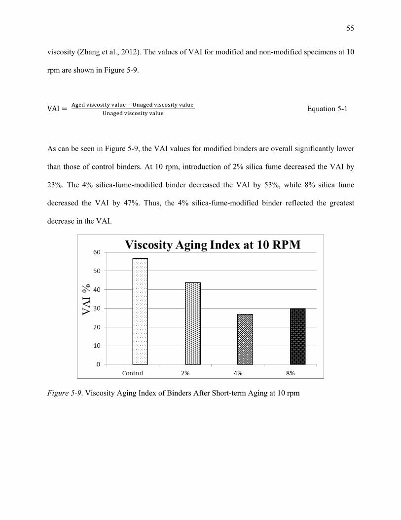
55
viscosity (Zhang et al., 2012). The values of VAI for modified and non-modified specimens at 10
rpm are shown in Figure 5-9.
VAI = !"#$ !"#$%#"&' !"#$% ! !"#$%& !"#$%#"&' !"#$% !"#$%& !"#$%#"&' !"#$%
Equation 5-1
As can be seen in Figure 5-9, the VAI values for modified binders are overall significantly lower
than those of control binders. At 10 rpm, introduction of 2% silica fume decreased the VAI by
23%. The 4% silica-fume-modified binder decreased the VAI by 53%, while 8% silica fume
decreased the VAI by 47%. Thus, the 4% silica-fume-modified binder reflected the greatest
decrease in the VAI.
Figure 5-9. Viscosity Aging Index of Binders After Short-term Aging at 10 rpm
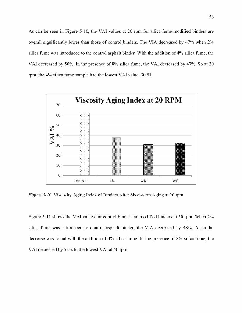
56
As can be seen in Figure 5-10, the VAI values at 20 rpm for silica-fume-modified binders are
overall significantly lower than those of control binders. The VIA decreased by 47% when 2%
silica fume was introduced to the control asphalt binder. With the addition of 4% silica fume, the
VAI decreased by 50%. In the presence of 8% silica fume, the VAI decreased by 47%. So at 20
rpm, the 4% silica fume sample had the lowest VAI value, 30.51.
Figure 5-10. Viscosity Aging Index of Binders After Short-term Aging at 20 rpm
Figure 5-11 shows the VAI values for control binder and modified binders at 50 rpm. When 2%
silica fume was introduced to control asphalt binder, the VIA decreased by 48%. A similar
decrease was found with the addition of 4% silica fume. In the presence of 8% silica fume, the
VAI decreased by 53% to the lowest VAI at 50 rpm.
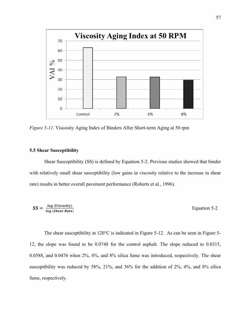
57
Figure 5-11. Viscosity Aging Index of Binders After Short-term Aging at 50 rpm
5.5 Shear Susceptibility
Shear Susceptibility (SS) is defined by Equation 5-2. Previous studies showed that binder
with relatively small shear susceptibility (low gains in viscosity relative to the increase in shear
rate) results in better overall pavement performance (Roberts et al., 1996).
𝑺𝑺 = 𝒍𝒐𝒈 (𝑽𝒊𝒔𝒄𝒐𝒔𝒊𝒕𝒚)𝒍𝒐𝒈 (𝑺𝒉𝒆𝒂𝒓 𝑹𝒂𝒕𝒆)
Equation 5-2
The shear susceptibility at 120°C is indicated in Figure 5-12. As can be seen in Figure 5-
12, the slope was found to be 0.0748 for the control asphalt. The slope reduced to 0.0315,
0.0588, and 0.0476 when 2%, 4%, and 8% silica fume was introduced, respectively. The shear
susceptibility was reduced by 58%, 21%, and 36% for the addition of 2%, 4%, and 8% silica
fume, respectively.
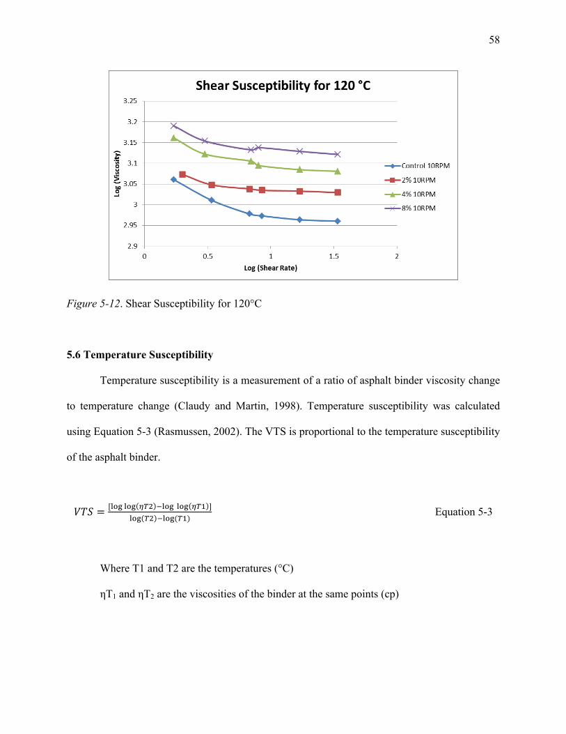
58
Figure 5-12. Shear Susceptibility for 120°C
5.6 Temperature Susceptibility
Temperature susceptibility is a measurement of a ratio of asphalt binder viscosity change
to temperature change (Claudy and Martin, 1998). Temperature susceptibility was calculated
using Equation 5-3 (Rasmussen, 2002). The VTS is proportional to the temperature susceptibility
of the asphalt binder.
𝑉𝑇𝑆 = [!"# !"# !"! !!"# !"# !"! ]!"# !! !!"#(!!)
Equation 5-3
Where T1 and T2 are the temperatures (°C)
ηT1 and ηT2 are the viscosities of the binder at the same points (cp)
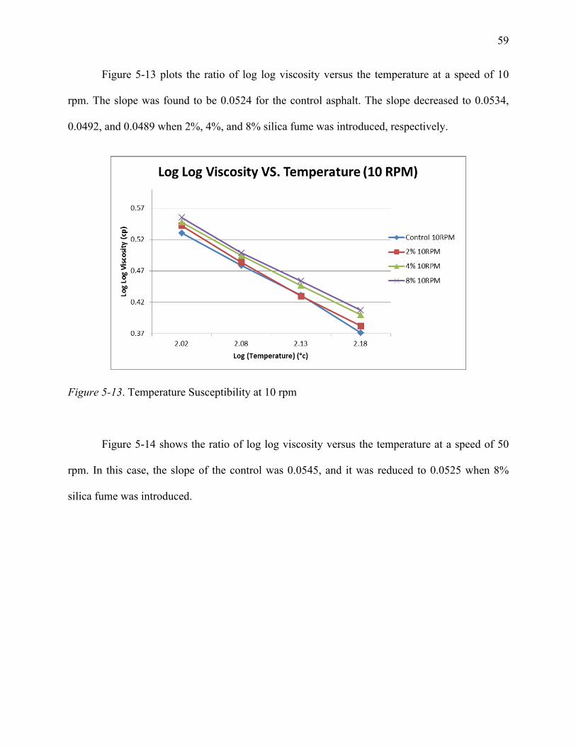
59
Figure 5-13 plots the ratio of log log viscosity versus the temperature at a speed of 10
rpm. The slope was found to be 0.0524 for the control asphalt. The slope decreased to 0.0534,
0.0492, and 0.0489 when 2%, 4%, and 8% silica fume was introduced, respectively.
Figure 5-13. Temperature Susceptibility at 10 rpm
Figure 5-14 shows the ratio of log log viscosity versus the temperature at a speed of 50
rpm. In this case, the slope of the control was 0.0545, and it was reduced to 0.0525 when 8%
silica fume was introduced.
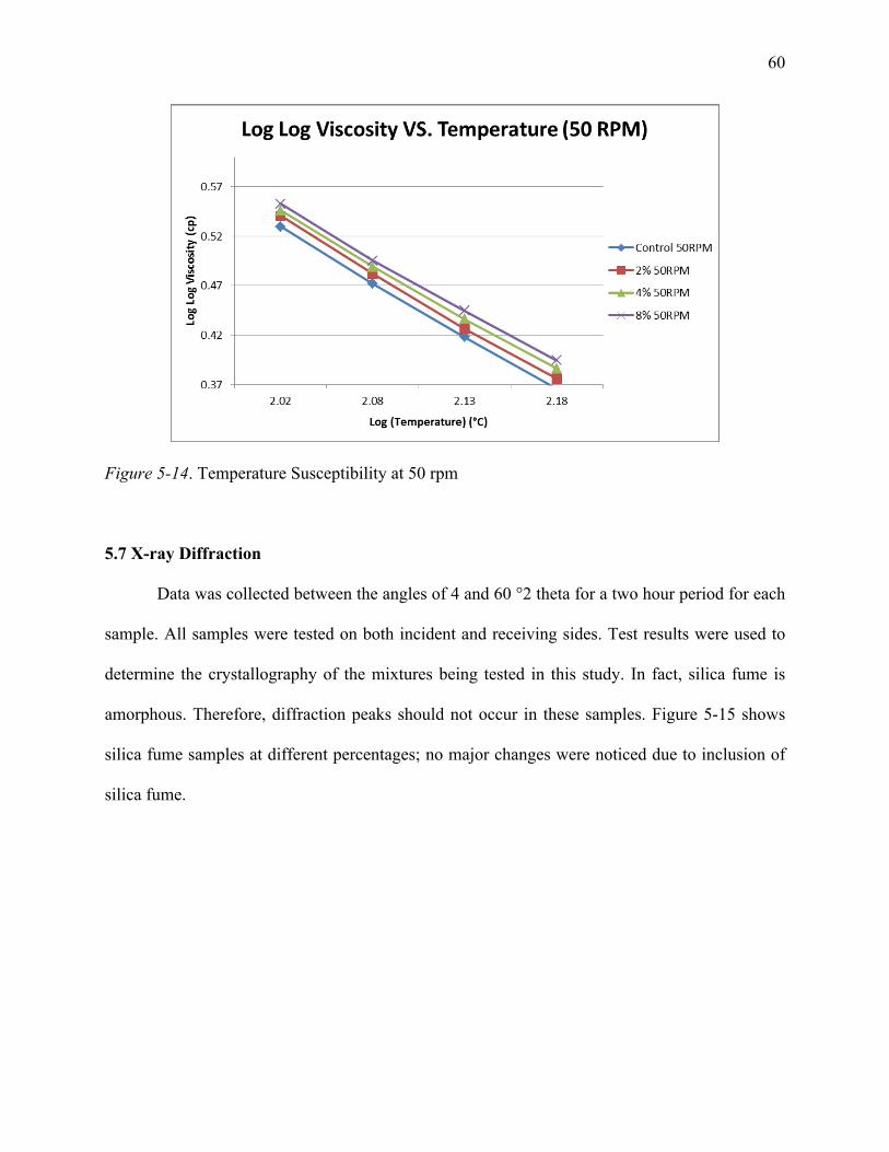
60
Figure 5-14. Temperature Susceptibility at 50 rpm
5.7 X-ray Diffraction
Data was collected between the angles of 4 and 60 °2 theta for a two hour period for each
sample. All samples were tested on both incident and receiving sides. Test results were used to
determine the crystallography of the mixtures being tested in this study. In fact, silica fume is
amorphous. Therefore, diffraction peaks should not occur in these samples. Figure 5-15 shows
silica fume samples at different percentages; no major changes were noticed due to inclusion of
silica fume.
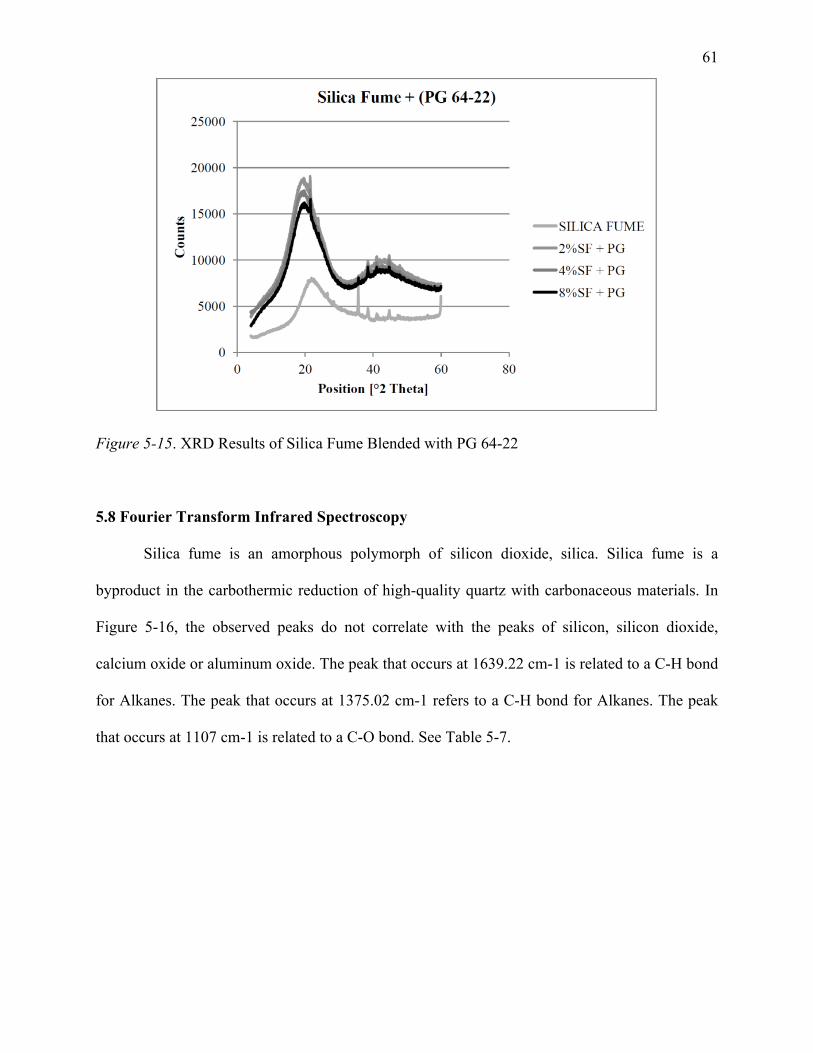
61
Figure 5-15. XRD Results of Silica Fume Blended with PG 64-22
5.8 Fourier Transform Infrared Spectroscopy
Silica fume is an amorphous polymorph of silicon dioxide, silica. Silica fume is a
byproduct in the carbothermic reduction of high-quality quartz with carbonaceous materials. In
Figure 5-16, the observed peaks do not correlate with the peaks of silicon, silicon dioxide,
calcium oxide or aluminum oxide. The peak that occurs at 1639.22 cm-1 is related to a C-H bond
for Alkanes. The peak that occurs at 1375.02 cm-1 refers to a C-H bond for Alkanes. The peak
that occurs at 1107 cm-1 is related to a C-O bond. See Table 5-7.
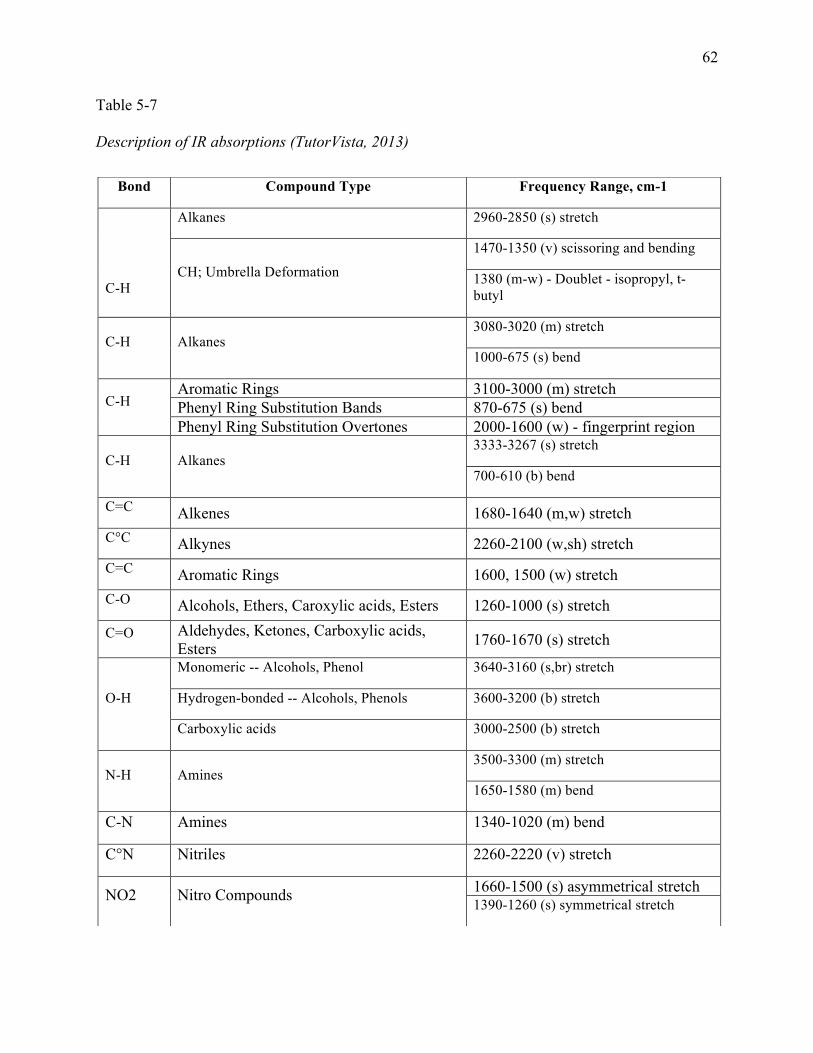
62
Table 5-7
Description of IR absorptions (TutorVista, 2013)
Bond Compound Type Frequency Range, cm-1
C-H
Alkanes 2960-2850 (s) stretch
CH; Umbrella Deformation 1470-1350 (v) scissoring and bending
1380 (m-w) - Doublet - isopropyl, t-butyl
C-H Alkanes 3080-3020 (m) stretch
1000-675 (s) bend
C-H Aromatic Rings 3100-3000 (m) stretch Phenyl Ring Substitution Bands 870-675 (s) bend Phenyl Ring Substitution Overtones 2000-1600 (w) - fingerprint region
C-H Alkanes 3333-3267 (s) stretch
700-610 (b) bend
C=C Alkenes 1680-1640 (m,w) stretch C°C Alkynes 2260-2100 (w,sh) stretch C=C Aromatic Rings 1600, 1500 (w) stretch C-O Alcohols, Ethers, Caroxylic acids, Esters 1260-1000 (s) stretch
C=O Aldehydes, Ketones, Carboxylic acids, Esters 1760-1670 (s) stretch
O-H
Monomeric -- Alcohols, Phenol 3640-3160 (s,br) stretch
Hydrogen-bonded -- Alcohols, Phenols 3600-3200 (b) stretch
Carboxylic acids 3000-2500 (b) stretch
N-H Amines 3500-3300 (m) stretch
1650-1580 (m) bend
C-N Amines 1340-1020 (m) bend
C°N Nitriles 2260-2220 (v) stretch
NO2 Nitro Compounds 1660-1500 (s) asymmetrical stretch 1390-1260 (s) symmetrical stretch
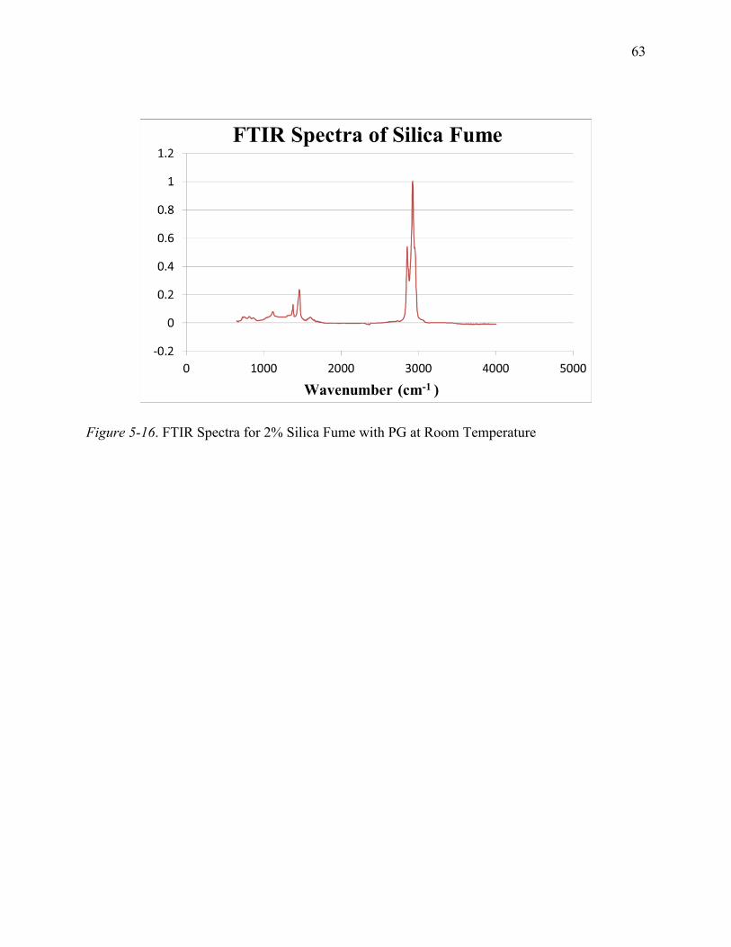
63
Figure 5-16. FTIR Spectra for 2% Silica Fume with PG at Room Temperature
64
CHAPTER 6
Discussion and Conclusions
6.1 Discussion
In this study, four laboratory tests were used: the Marshall test, the Rotational Viscosity
(RV) test, the X-ray Diffraction (XRD) test, and the Fourier Transform Infrared Spectroscopy
(FTIR) test. These tests were conducted at the Civil Engineering Laboratory at North Carolina
A&T State University and at the Centre for Material Science and Engineering at Massachusetts
Institute of Technology. Samples were prepared with different percentages of silica fume mixed
with asphalt binder to identify the effects of adding silica fume to the asphalt binder.
The Marshall test was conducted to determine the stability and flow. Three different
percentages of silica fume were added to a control asphalt binder AC 60-70. It was shown that
adding silica fume can reduce the loss of stability, indicating that the silica fume particles can
help improve the mixture stability while enhancing the workability.
The (RV) test was used to measure viscosity based on the rate of deformation due to an
applied shear stress. 2%, 4%, and 8% samples were each tested three times. Temperature was set
at the target temperature for different shear rates of 5, 10, 20, 25, 50, and 75 RPM. Data was
collected for all six shear rates at temperatures of 105°C, 120°C, 135°C, and 150°C. The average
of the three measurements was used to represent the viscosity of the sample at a specified
temperature and shear rate. The collected data were then used to calculate the temperature
susceptibility and shear susceptibility of each modified sample. It was shown that the viscosity
increased with the addition of silica fume to the control asphalt binder (PG 64-22). Moreover, it
was found that the 8% silica fume mixed with PG 64-22 has the lowest temperature
susceptibility, followed by the 4% silica fume mixture.
65
The XRD test was used to determine the crystalline structure of silica fume added to PG
64-22. The sample was tested for two hours. Crystalline structure causes the incident ray to
diffract in various directions. The angles and intensities of the diffracted rays were measured.
Consequently, the density of the electrons within the crystal was clearly shown. The incident ray
angle range was 4 – 60 degrees. Using a computer program, the peaks formed based on the
crystalline structure of each sample were then analyzed, and the layer spacing was calculated.
The results for the silica fume samples indicated that adding silica fume had little to no impact
on the layer spacing, due to the non-crystalline form of silica fume.
The FTIR test was used to determine the compatibility of the silica fume with the asphalt
binder. This test showed the formation of chemical bonds between silica fume and asphalt
binder. The results of this test were dependent upon the shear rate (rate at which a sample was
mixed) and compatibility of the asphalt binder used (PG 64-22). It showed the chemical
components of silica fume associated with the description of IR absorptions table.
6.2 Conclusions
To reduce the oxidation rate of asphalt binder, silica fume was added to the base asphalt
binder PG 64-22 at various percentages. The effectiveness of silica fume in reducing asphalt
oxidation aging was evaluated experimentally. Four laboratory tests were conducted: the
Marshall test, the X-ray Diffraction (XRD) test, the Fourier Transform Infrared Spectroscopy
(FTIR) test, and the Rotational Viscosity (RV) test. Marshall tests were conducted to determine
the stability and flow. It was shown that adding silica fume reduces loss of stability. The XRD
and FTIR tests were used to study the crystalline structure of specimens and their chemical
compositions. Study of viscosity results showed that significant increases in viscosity can be
obtained by addition of silica fume to the control asphalt binder. Analysis of the experiment
66
results further showed that introduction of silica fume in asphalt binder can significantly reduce
its oxidative aging in addition to enhancing stability and flow. The improvement was more
noticeable at higher percentages of silica fume, up to 4%. However, above 4%, silica fume
appeared to negatively affect the aging index, as measured by a higher aging index at 8% silica
fume. The results of this research are expected to promote pavement service life by reducing
oxidative aging while enhancing pavement sustainability and facilitating use of an industrial
waste, silica fume.
It was found that 4% silica-fume-modified binder reduced oxidative aging by 50%, with a
relatively low viscosity aging index (VAI) of 30.51. This is in line with the findings of prior
research, which showed that introduction of 4% nano-silica could reduce oxidative aging by 29%
(Onochie, 2013). It should be noted that silica fume was even more effective than nano-silica
when the same percentages were used, and silica fume is currently considered an industrial waste
and is frequently available at relatively low cost. Considering that the surface area of nano-silica
is much higher than that of silica fume, nano-silica could be expected to be more effective in
interacting with asphalt binder. However, the better aging performance of silica fume relative to
nano-silica that was observed in this study could be attributed to a reduction in the agglomeration
typically observed for nano-silica; agglomeration has been recognized as a problem in dealing
with nano-silica. Therefore, the reduced agglomeration in silica fume could be linked to its
improved oxidative aging performance.
6.3 Future Research
Further research is needed to specify the interaction mechanisms between silica fume and
asphalt molecules. In addition, the optimum percentages of each additive should be determined
in order to maximize the resulting improvement in asphalt binder aging resistance. Thus, it is

67
recommended that the molecular interactions between silica fume and asphalt binder be studied
to provide in-depth understanding of the underlying mechanisms controlling the rheological
properties of silica-fume-modified asphalt.
68
References
ASTM International. (2013). Products and Services, Standards and Publications. Accessed on
May 21, 2014, from: www.astm.org.
Association of Asphalt Paving Technologists Technical Sessions. (1985). Marshall Procedures
for Design and Quality Control of Asphalt Mixtures. Asphalt Paving Technology, 54,
265-284.
Amirkhanian, A., Xiao, F., & Amirkanian, S. (2011). Evaluation of High Temperature
Rheological Characteristics of Asphalt Binder with Carbon Nano Particles. Journal of
Testing and Evaluation, 39 (4), 583-591.
Claudy, P., & Martin, D. (1998). Thermal Behavior of Asphalt Cements. Thermochemical Act.,
324, 203-213.
Dutrow, B., & Clark, C. (2013). X-ray Powder Diffraction (XRD). The Science Education
Resource Center at Carleton College. Accessed on June 19, 2014, from:
http://serc.carleton.edu/research_education/geochemsheets/techniques/XRD.html
Federal Highway Administration (2012). Silica Fume. Washington, DC: United States
Department of Transportation. Accessed on August 19, 2013, from:
http://www.fhwa.dot.gov/infrastructure/materialsgrp/silica.htm
Gapinski, G., & Scanlon, J. (2011). Silica Fume. Norchem, Inc. Accessed on September 04,
2013, from: http://www.norchem.com/pdf/technical-papers-articles-gapinksi-scanlon.pdf.
Haipeng, J., Huang, Z., Chen, K., Li, W., Gao, Y., Fang, M., Liu, Y., & Wu, X. (2014).
Synthesis of Si3N4 powder with tunable α/β-Si3N4 content from waste silica fume using
carbothermal reduction nitridation. Powder Technology, 252, 51–55.
69
Hosseini, S., Madaeni, S., & Khodabakhshi, A. (2010). Preparation and Characterization of
ABS/HIPS Heterogeneous Anion Exchange Membrane Filled with Activated Carbon. J.
Appl. Polym. Sci., 118, 3371–3383.
Huang, S., Glaser, R., & Turner, F. (2012). Impact of Water on Asphalt Aging: Chemical Aging
Kinetic Study. Transportation Research Record, 2293, 63-72.
Khayat, K., Vachon, M., & Lanctot, M. (1997). Use of Blended Silica Fume Cement in
Commercial Concrete Mixtures. Materials Journal, 94 (3), 183-192.
Langan, B., Weng, K., & Ward, M.A. (2002). Effect of Silica Fume and Fly Ash on Heat of
Hydration of Portland Cement. Cement and Concrete Research, 32, 1045-1051.
Lavin, P. (2003). Asphalt Pavements: A Practical Guide to Design, Production and Maintenance
for Engineers and Architects. London: Spon Press.
Lee, L., Zeng, C., Cao, X., Han, X., Shen, J., & Xu, G. (2005). Polymer Nanocomposite.
Composites Science and Technology, 65, 2344-2363.
Lu, X., & Isacsson, U. (2002). Effect of ageing on bitumen chemistry and rheology.
Construction and Building Materials, 16 (1), 15-22.
Mikoc, M., & Markovic, D. (2010). Influence Of Slag, Fly Ash and Silica Fume on the
Mechanical and Physical Properties of Asphalt. Technical Gazette, 17(4), 505-514.
Onochie, A., Fini, E., Yang, X., Mills-Beale, J., & You, Z. (2013). Rheological Characterization
of Nano-particle based Bio-modified Binder. Transportation Research Board 92nd annual
Meeting. Washington, DC: Transportation Research Board. Available from:
http://pubsindex.trb.org/view/2013/C/1242863
Parviz, A. (2011). Nano Materials in Asphalt and Tar. Australian Journal of Basic and Applied
Sciences, 5(12), 3270-3273.
70
Rasmussen, R., Robert, L., & George, C. (2002). Method to Predict Temperature Susceptibility
of an Asphalt Binder. Journal of Materials in Civil Engineering, 14, 246-252.
Roberts F., Kandhal, P., Brown, E., Lee, D., & Kennedy, T. (1996). Hot Mix Asphalt Materials,
Mixture Design & Construction. Lanham, MD: National Asphalt Pavement Association.
Silica Fume Association. (2005). Silica Fume User's Manual. Accessed July 14, 2014 from:
http://www.silicafume.org/concrete-manual.html
Specialists in Business Information (SBI). (2009). Report on Asphalt Manufacturing in the U.S.
Accessed on April 30, 2014, from: http://www.sbireports.com/about/release.asp?id=1475
U.S. Oil & Refining Co. (n.d.). Paving Grade Asphalt, PG64-22. Accessed on May 27, 2014
from: http://www.usor.com/files/pdf/6/PG64-22.pdf.
Yildirim, Y. (2007). Polymer modified asphalt binders. Construction and Building Materials, 21,
66-72.
You, Z., Beale, J., Foley, J., Roy, S., Odegard, G., Dai, Q., & Wei Goh, S. (2011). Nanoclay-
modified asphalt materials: Preparation and characterization. Journal of Construction
and Building Materials, 25, 1072-1078.
Yu, J., Wang, X., Hu, L., & Tao, Y. (2010). Effect of Various Organomodified
Montmorillonite/Bitumen Nanocomposites. Journal of Materials in Civil Engineering,
22 (8), 788-793.
Zhang, H., Yu, J, & Wu, S. (2012). Effect of montmorillonite organic modification on
ultraviolet aging properties of SBS modified bitumen. Construction Building Materials,
27, 553-559.