Embed Size (px)
Citation preview
A Test Methodology for Copper Dissolution in Lead-Free Alloys
Christopher Hunt and Davide Di Maio
National Physical Laboratory
Teddington, UK
Abstract
Lead-free selective soldering can result in extended times at high temperatures, which in turn can result in excessive
dissolution of exposed copper, such as plated through holes. This phenomenon is more severe with lead-free, since the
alloys have higher melting points, hence requiring longer times for the PTH to reach the higher temperatures, and the alloys
typically have a greater capacity to dissolve copper.
This paper discusses a test method that characterises the dissolution rate of copper from PWBs. A PWB design was created
that allowed the time for the dissolution of a copper pad to be measured. With this quantitative method a soldering process
or an alloy can be characterised in terms of dissolution rates at specific conditions of temperature and flow rate. This
methodology provided repeatable measurements that allowed the various experimental parameters to be isolated. Particular
attention was paid at the flow rate of the molten solder. In fact, different alloys at the same temperature can have
considerably different flow rates, due to the different viscosity at that temperature. The performances of seven lead-free
alloys and a typical 60/40 Sn-Pb alloy were compared at three temperatures.
NPL worked with a number of partners using different alloys and copper types to measure the relative rate of copper
dissolution. This work shows that some of the current alloy developments now offer superior performance to SnPb at the
same temperature. Interestingly intermetallic formation between the alloy systems varies considerably. The copper type on
the PWB is also influential, with significant differences between electroplated, electrodeposited and reverse treated.
Introduction
The advent of lead-free soldering has resulted in the introduction of a number of high tin solder alloys, which for selective
soldering applications typically means solders with melting temperatures in excess of 220°C. The higher melting points of
the lead-free alloys also dictate higher processing temperatures, and usually higher contact times, as the components take
longer to heat up to the higher processing temperature. The copper dissolution process is temperature and solder alloy
dependent. The solubility of copper in the new lead free alloys with tin compositions of at least 95% tin is potentially higher
than that of tin-lead solder. Hence, the higher temperature and solubility effects can significantly increase the risk of
damaging copper dissolution. Exposed surface copper can be removed, disconnecting the land from the track.
The formation of a solder joint during soldering requires a reaction between the solder and the metallisation of the substrate.
This reaction involves a dissolution process, which occurs through an intermediate phase, an intermetallic that forms at the
interface. The intermetallic itself is soluble in molten solder, and hence the intermetallic substrate interface proceeds into the
substrate with time. The nature of this intermetallic and its thickness will be significant in controlling the overall copper
dissolution process. A number of alloys are now available where additions significantly below 1% affect a number of
material properties, of which the solubility of copper is an important parameter.
Factors Affecting Dissolution of Copper
When a copper substrate is in contact with molten solder, atoms of copper will tend to diffuse into the molten metal and a
diffusion zone is created on top of the copper surface [1]. The Nernst Brunner equation, often referred as Dybkov's analysis
was found to be valid to explain this part of the dissolution process:
)(= ccV
Sk
dt
dcs (1)
where cs is the solubility of copper in the molten solder at the specific temperature, c is the concentration of copper in the
solder, S is the surface area of the copper, V is the volume of the molten solder and k is a constant [2, 3, 4].
As originally published in the IPC APEX EXPO Proceedings.
The diffusion of copper atoms into the molten solder, favours the formation of intermetallic layers, such as the scalloped
Cu6Sn5 (η) and the planar Cu3Sn (ε) [5]. The microstructure of these two compounds plays a role in copper diffusion; a
coarsening of the η grains reduces the number of grain boundaries, decreasing possible diffusion paths for copper [2]. Grain
boundary diffusion is the predominant mechanism for intermetallic growth and has a great influence on the copper
dissolution rate [4]. The morphology of the intermetallic is important, and can fully or just partially cover the copper [6].
Furthermore, the η intermetallic phase has a higher melting point than that of tin or eutectic Sn/Cu, and hence has a lower
dissolution rate. This suggests that a uniform layer of this phase at the interface can reduce the formation rate of further
intermetallic, and hence reduce copper dissolution [7]. The balance between the intermetallic formation, its microstructure
and morphology is significant in controlling the whole dissolution process.
The type of solder used in the process has an important effect on the dissolution rate of copper. This is related to the
elements contained in lead-free alloys, both alloying and trace elements, such as Cu, Ag, Ni, Bi, In, Zn, Sb and small
amounts of Pb. All these can form intermetallics that can attach to the surface of the copper. For example Ag, used in SAC
alloys, forms the Ag3Sn intermetallic. This tends to precipitate near the interfacial intermetallic and be “absorbed'' by this
layer, hence reducing the interfacial energy. It was observed that in presence of Ag3Sn, the intermetallic layer becomes
thinner than that formed with just Sn/Cu [4]. Also, it is expected that a higher amount of Cu in the solder will reduce the
dissolution process [8].
Different solder compositions will have different melting temperatures; hence the optimal operating temperature for each
alloy will be different, and this temperature change will impact on copper dissolution. Typically the higher the temperature
the higher the copper dissolution rate, for two principal reasons: Firstly the saturated copper concentration increases with
temperature; secondly the dissolution rate follows Arrhenius behaviour:
RT
EAexpK a= (2)
Where K is the dissolution rate, A is a constant independent of temperature, Ea is the activation energy and R is the gas
constant [3, 9].
In a solder bath the solder is static and the concentration of copper in the solder near the interface can be expected to
increase with time and hence the dissolution rate decreases due to concentration and solubility effects. In flowing solder the
dissolved copper will be continuously swept away from the interface, leaving the cs –c difference of equation 1 unchanged.
The flow rate of solder is another important parameter, and it has been observed that copper dissolution rate is highly
dependent on flow conditions [10]. In fact, a high turbulent flow generates a mechanical erosion effect of the copper surface
(or actually of the intermetallic) [11]. The flow rate and flow type in the solder bath are dependent on many variables, such
as the machine geometry and type, the pump speed and solder viscosity. Different types of soldering machines, for example
the rework fountain and wave soldering present very different types of flow, depending on their construction and operating
conditions. For this reason dissolution rates can be very dissimilar, even when operating at the same temperature. Varying
the pump speed is the easiest way to change the flow rate and type of flow, however not all machines allow this to be
controlled. If the pump speed is fixed, then the flow rate can be varied by changing the operating temperature, and hence the
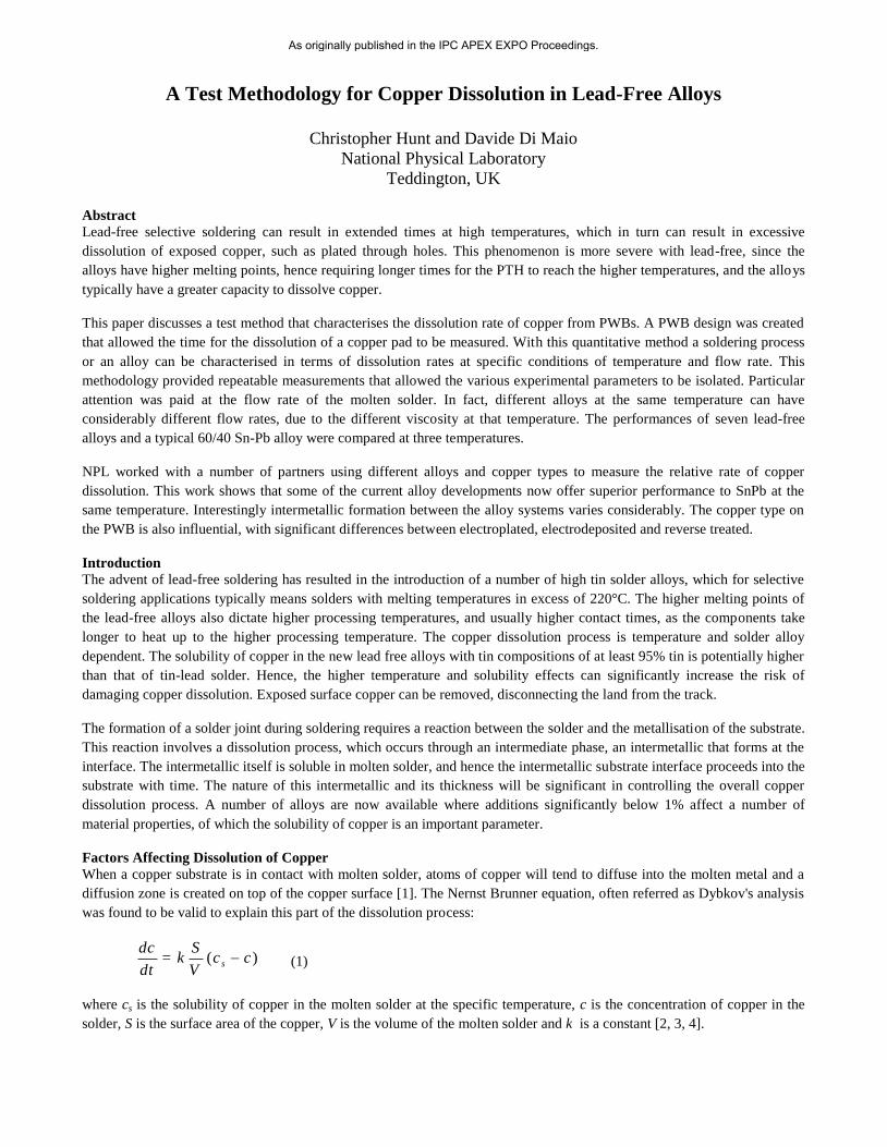
solder viscosity. Figure 1 shows how the viscosity dependence of tin with temperature [12].
Potentially the type of copper microstructure can affect its dissolution resistance. Large variations have been observed in the
performance of different copper types [13, 14], however this dependency has not been investigated fully. Work to
demonstrate a correlation between microstructure/mechanical properties with dissolution propensity was not
successful [15], and the effect of microstructure and factors within the copper, such as composition, need to be studied
further.
As originally published in the IPC APEX EXPO Proceedings.
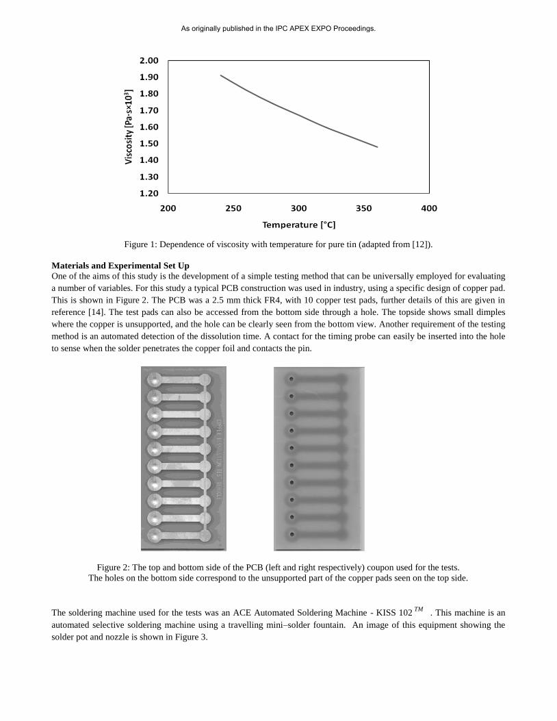
Figure 1: Dependence of viscosity with temperature for pure tin (adapted from [12]).
Materials and Experimental Set Up
One of the aims of this study is the development of a simple testing method that can be universally employed for evaluating
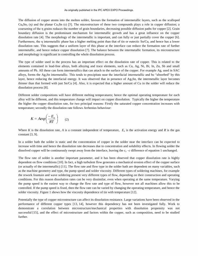
a number of variables. For this study a typical PCB construction was used in industry, using a specific design of copper pad.
This is shown in Figure 2. The PCB was a 2.5 mm thick FR4, with 10 copper test pads, further details of this are given in
reference [14]. The test pads can also be accessed from the bottom side through a hole. The topside shows small dimples
where the copper is unsupported, and the hole can be clearly seen from the bottom view. Another requirement of the testing
method is an automated detection of the dissolution time. A contact for the timing probe can easily be inserted into the hole
to sense when the solder penetrates the copper foil and contacts the pin.
Figure 2: The top and bottom side of the PCB (left and right respectively) coupon used for the tests.
The holes on the bottom side correspond to the unsupported part of the copper pads seen on the top side.
The soldering machine used for the tests was an ACE Automated Soldering Machine - KISS 102TM
. This machine is an
automated selective soldering machine using a travelling mini–solder fountain. An image of this equipment showing the
solder pot and nozzle is shown in Figure 3.
As originally published in the IPC APEX EXPO Proceedings.
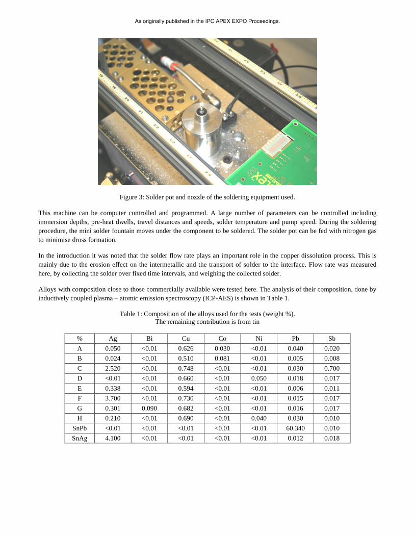
Figure 3: Solder pot and nozzle of the soldering equipment used.
This machine can be computer controlled and programmed. A large number of parameters can be controlled including
immersion depths, pre-heat dwells, travel distances and speeds, solder temperature and pump speed. During the soldering
procedure, the mini solder fountain moves under the component to be soldered. The solder pot can be fed with nitrogen gas
to minimise dross formation.
In the introduction it was noted that the solder flow rate plays an important role in the copper dissolution process. This is
mainly due to the erosion effect on the intermetallic and the transport of solder to the interface. Flow rate was measured
here, by collecting the solder over fixed time intervals, and weighing the collected solder.
Alloys with composition close to those commercially available were tested here. The analysis of their composition, done by
inductively coupled plasma – atomic emission spectroscopy (ICP-AES) is shown in Table 1.
Table 1: Composition of the alloys used for the tests (weight %).
The remaining contribution is from tin
% Ag Bi Cu Co Ni Pb Sb
A 0.050 <0.01 0.626 0.030 <0.01 0.040 0.020
B 0.024 <0.01 0.510 0.081 <0.01 0.005 0.008
C 2.520 <0.01 0.748 <0.01 <0.01 0.030 0.700
D <0.01 <0.01 0.660 <0.01 0.050 0.018 0.017
E 0.338 <0.01 0.594 <0.01 <0.01 0.006 0.011
F 3.700 <0.01 0.730 <0.01 <0.01 0.015 0.017
G 0.301 0.090 0.682 <0.01 <0.01 0.016 0.017
H 0.210 <0.01 0.690 <0.01 0.040 0.030 0.010
SnPb <0.01 <0.01 <0.01 <0.01 <0.01 60.340 0.010
SnAg 4.100 <0.01 <0.01 <0.01 <0.01 0.012 0.018
As originally published in the IPC APEX EXPO Proceedings.
Experimental Results
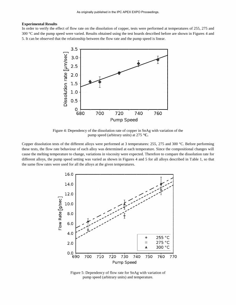
In order to verify the effect of flow rate on the dissolution of copper, tests were performed at temperatures of 255, 275 and
300 °C and the pump speed were varied. Results obtained using the test boards described before are shown in Figures 4 and
5. It can be observed that the relationship between the flow rate and the pump speed is linear.
Figure 4: Dependency of the dissolution rate of copper in SnAg with variation of the
pump speed (arbitrary units) at 275 °C.
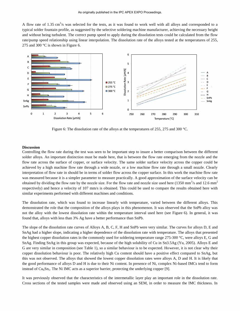
Copper dissolution tests of the different alloys were performed at 3 temperatures: 255, 275 and 300 °C. Before performing
these tests, the flow rate behaviour of each alloy was determined at each temperature. Since the compositional changes will
cause the melting temperature to change, variations in viscosity were expected. Therefore to compare the dissolution rate for
different alloys, the pump speed setting was varied as shown in Figures 4 and 5 for all alloys described in Table 1, so that
the same flow rates were used for all the alloys at the given temperatures.
Figure 5: Dependency of flow rate for SnAg with variation of
pump speed (arbitrary units) and temperature.
As originally published in the IPC APEX EXPO Proceedings.
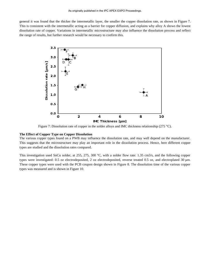
A flow rate of 1.35 cm3/s was selected for the tests, as it was found to work well with all alloys and corresponded to a
typical solder fountain profile, as suggested by the selective soldering machine manufacturer, achieving the necessary height
and without being turbulent. The correct pump speed to apply during the dissolution tests could be calculated from the flow
rate/pump speed relationship using linear interpolation. The dissolution rate of the alloys tested at the temperatures of 255,
275 and 300 °C is shown in Figure 6.
Figure 6: The dissolution rate of the alloys at the temperatures of 255, 275 and 300 °C.
Discussion
Controlling the flow rate during the test was seen to be important step to insure a better comparison between the different
solder alloys. An important distinction must be made here, that is between the flow rate emerging from the nozzle and the
flow rate across the surface of copper, or surface velocity. The same solder surface velocity across the copper could be
achieved by a high machine flow rate through a wide nozzle, or a low machine flow rate through a small nozzle. Clearly
interpretation of flow rate in should be in terms of solder flow across the copper surface. In this work the machine flow rate
was measured because it is a simpler parameter to measure practically. A good approximation of the surface velocity can be
obtained by dividing the flow rate by the nozzle size. For the flow rate and nozzle size used here (1350 mm3/s and 12.6 mm
2
respectively) and hence a velocity of 107 mm/s is obtained. This could be used to compare the results obtained here with
similar experiments performed with different machines and conditions.
The dissolution rate, which was found to increase linearly with temperature, varied between the different alloys. This
demonstrated the role that the composition of the alloys plays in this phenomenon. It was observed that the SnPb alloy was
not the alloy with the lowest dissolution rate within the temperature interval used here (see Figure 6). In general, it was
found that, alloys with less than 3% Ag have a better performance than SnPb.
The slope of the dissolution rate curves of Alloys A, B, C, F, H and SnPb were very similar. The curves for alloys D, E and
SnAg had a higher slope, indicating a higher dependence of the dissolution rate with temperature. The alloys that presented
the highest copper dissolution rates in the commonly used for soldering temperature range 275-300 °C, were alloys E, G and
SnAg. Finding SnAg in this group was expected, because of the high solubility of Cu in Sn3.5Ag (Yu, 2005). Alloys E and
G are very similar in composition (see Table 1), so a similar behaviour is to be expected. However, it is not clear why their
copper dissolution behaviour is poor. The relatively high Cu content should have a positive effect compared to SnAg, but
this was not observed. The alloys that showed the lowest copper dissolution rates were alloys A, D and H. It is likely that
the good performance of alloys D and H is due to their Ni content. In presence of Ni, complex Ni-based IMCs tend to form
instead of Cu6Sn5. The Ni IMC acts as a superior barrier, protecting the underlying copper [9].
It was previously observed that the characteristics of the intermetallic layer play an important role in the dissolution rate.
Cross sections of the tested samples were made and observed using an SEM, in order to measure the IMC thickness. In
As originally published in the IPC APEX EXPO Proceedings.
general it was found that the thicker the intermetallic layer, the smaller the copper dissolution rate, as shown in Figure 7.
This is consistent with the intermetallic acting as a barrier for copper diffusion, and explains why alloy A shows the lowest
dissolution rate of copper. Variations in intermetallic microstructure may also influence the dissolution process and reflect
the range of results, but further research would be necessary to confirm this.
Figure 7: Dissolution rate of copper in the solder alloys and IMC thickness relationship (275 °C).
The Effect of Copper Type on Copper Dissolution
The various copper types found on a PWB may influence the dissolution rate, and may well depend on the manufacturer.
This suggests that the microstructure may play an important role in the dissolution process. Hence, here different copper
types are studied and the dissolution rates compared.
This investigation used SnCu solder, at 255, 275, 300 °C, with a solder flow rate: 1.35 cm3/s, and the following copper
types were investigated: 0.5 oz electrodeposited, 2 oz electrodeposited, reverse treated 0.5 oz, and electroplated 30 μm.
These copper types were used with the PCB coupon design shown in Figure 8. The dissolution time of the various copper
types was measured and is shown in Figure 10.
As originally published in the IPC APEX EXPO Proceedings.
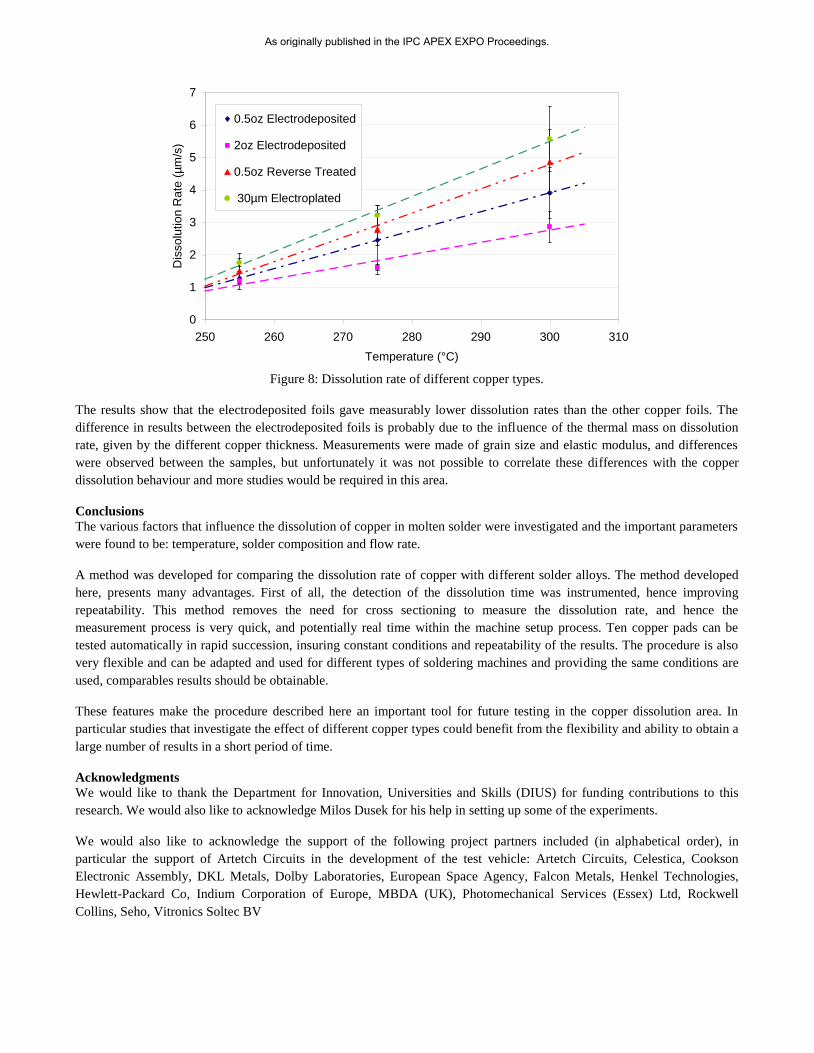
Figure 8: Dissolution rate of different copper types.
The results show that the electrodeposited foils gave measurably lower dissolution rates than the other copper foils. The
difference in results between the electrodeposited foils is probably due to the influence of the thermal mass on dissolution
rate, given by the different copper thickness. Measurements were made of grain size and elastic modulus, and differences
were observed between the samples, but unfortunately it was not possible to correlate these differences with the copper
dissolution behaviour and more studies would be required in this area.
Conclusions
The various factors that influence the dissolution of copper in molten solder were investigated and the important parameters
were found to be: temperature, solder composition and flow rate.
A method was developed for comparing the dissolution rate of copper with different solder alloys. The method developed
here, presents many advantages. First of all, the detection of the dissolution time was instrumented, hence improving
repeatability. This method removes the need for cross sectioning to measure the dissolution rate, and hence the
measurement process is very quick, and potentially real time within the machine setup process. Ten copper pads can be
tested automatically in rapid succession, insuring constant conditions and repeatability of the results. The procedure is also
very flexible and can be adapted and used for different types of soldering machines and providing the same conditions are
used, comparables results should be obtainable.
These features make the procedure described here an important tool for future testing in the copper dissolution area. In
particular studies that investigate the effect of different copper types could benefit from the flexibility and ability to obtain a
large number of results in a short period of time.
Acknowledgments
We would like to thank the Department for Innovation, Universities and Skills (DIUS) for funding contributions to this
research. We would also like to acknowledge Milos Dusek for his help in setting up some of the experiments.
We would also like to acknowledge the support of the following project partners included (in alphabetical order), in
particular the support of Artetch Circuits in the development of the test vehicle: Artetch Circuits, Celestica, Cookson
Electronic Assembly, DKL Metals, Dolby Laboratories, European Space Agency, Falcon Metals, Henkel Technologies,
Hewlett-Packard Co, Indium Corporation of Europe, MBDA (UK), Photomechanical Services (Essex) Ltd, Rockwell
Collins, Seho, Vitronics Soltec BV
0
1
2
3
4
5
6
7
250 260 270 280 290 300 310
Temperature (°C)
Dis
solu
tion
Rate
(µm
/s)
0.5oz Electrodeposited
2oz Electrodeposited
0.5oz Reverse Treated
30µm Electroplated
As originally published in the IPC APEX EXPO Proceedings.
References
1. Yu C.H., Lin, K.L., (2006), “The atomic-scale studies of the behaviour of the crystal dissolution in molten metal”,
Chemical Physics Letters, Vol. 418, pp. 433–436.
2. Huang, M.L., Loeher, T., Ostmann, A. and Reichl, H., (2005), “Role of copper in dissolution kinetics of copper
metallization in molten tin-based solders”, Applied Physics Letters, Vol. 86, No. 18 , pp. 181908.
3. Izuta, G., Tanabe, T., Suganuma, K., (2007), “Dissolution of Sn-Ag-Cu System Lead-Free Solder”, Soldering &
Surfac Mount Technology, Vol. 19 No. 2, pp. 4-11.
4. Yu, D.Q., Wu, C.M.L., Law, C.M.T., Wang, L. and Lai, J.K.L., (2005), “Intermetallic compounds growth between
Sn-3.5Ag lead-free solder and copper substrate by dipping method”, Journal of Alloys and Compounds Vol. 392.
5. Yen, Y.W., Chou, W.T., Tseng, Y. and Lee, C., (2008), “Investigation of Dissolution Behaviour of Metallic Substrates
and Intermetallic Compound in Molten Lead-free Solders”, Journal of Electronic Materials, Vol. 37, No. 1, pp. 73-83.
6. Mannan, S. and Clode, M.P., (2004) “Dissolution of Solids in Contact with Liquid Solder”, Soldering & Surface
Mount Technology, Vol. 16, No. 3, pp. 31-33.
7. Shih, R.L.H, Lau, D.Y.K. and Kwok, R.W.M., (2003), “Metallurgy and Stability of the Sn/copper Interface for Lead-
Free Flip Chip Application”, Int. Conference on Electronic Packaging Technology.
8. Alam, M.O., Chan, Y.C., Tu, K.N., (2003), “Effect of 0.5 wt% Cu addition in Sn–3.5%Ag solder on the dissolution
rate of Cu metallization”, Journal of Applied Physics, Vo. 94, No. 12, pp. 7904-7909
9. Hamilton, C., and Snugovsky, P., (2007), “A Study of Copper Dissolution During Lead Free PTH Rework Using a
Thermally Massive Vehicle”, SMTA International (2007).
10. Byle, F., Jean, D. and Lee, D., (2006), “A Study of Copper Dissolution in Pb-Free Solder Fountain Systems” , SMTAi,
PanPacific Microelectronics Symposium.
11. Hamilton, C. and P. Snugovsky, P. , (2007), “Have a High copper Dissolution Rates of SAC305/405 Alloys Forced a
Change in The Lead Free Alloy Used During PTH Process?”, SMTAi, PanPacific Microelectronics Symposium.
12. Lewis, A. L., (1936), “The Absolute Measurement of the Viscosity of Liquid Tin”, Proceedings of the Physical
Society, Vol. 48 pp. 102-110.
13. Shea, C., Kenny, J., Rasmussen, J., Wable, G., Chu, Q., Teng, S., Sweatman, K., Nogita, K., (October 2008), “Copper
erosion: the Influence of metallurgy on copper dissolution: the rate of copper dissolution in lead-free soldering may be
linked to the physical characteristics of the electroplated copper.” Printed Circuit Design & Fabrication.
14. Di Maio, D., Hunt, C.P., (2009), “Measurements of Copper Dissolution in Lead-Free Alloys”, NPL Report, MAT 26
ISSN: 1754-2979, National Physical Laboratory, Teddington, UK.
15. Shea C., and J Kenny, J., (2007) The Influence of the PWB Fabrication Electrodeposition Process on Copper Erosion
During Wave Soldering, IPC Midwest Conference, Pan Pacific Symposium.
As originally published in the IPC APEX EXPO Proceedings.