Embed Size (px)
Citation preview

Tim Hurley, GPT Industries, USA, explains the differences between a standard gasket and an isolation kit, and the importance of properly installing them.
A s one of the world’s largest manufacturers of isolation kits, GPT’s engineers have seen a significant number of isolation kit failures. The engineering team performs forensic analyses on
the kits to determine the root cause (or causes) of failure and document the information. An overwhelming number of failures occur due to improper installation.
Up until this point, no isolation kit installation classes have existed. This is of importance because there are a large number of differences between installing a standard gasket and an isolation kit. If a field crew was asked to install a standard 24 in./600# gasket, the task is relatively straightforward as it is simply a gasket that will be installed. However, if a field crew was asked to install a 24 in./600# isolation kit, they are being asked to handle 193 pieces of equipment just to install that one kit (Figure 1).
With every component touched, there is a chance that something could go wrong. The sleeves could be too short or too long, or the washers could be put in backwards. This is a huge problem with isolation kits as when using GRE and metal-based washers, it can ruin the isolation properties of the entire kit if just one set of washers is reversed. The nut could be put on backwards – the flat side of the nut should face the washers, while the printed side of the nut should be visible. As a result, the raised, printed surface of the nut creates friction and can give incorrect lb/ft readings and rob the isolation gasket of the load that is needed to properly seal. The installation team could also damage
World Pipelines / REPRINTED FROM APRIL 2020
Figure 1. 24 in./600# flange = 193 individual components.
the sleeves while inserting through the bolt holes. They are being asked not only to seal that flanged connection, but also to ensure that the isolation properties of the flange are optimised so that either the cathodic protection (CP) system can do its job well and prevent corrosion throughout the structure, or that the dissimilar metals in the flange have no metallic path for galvanic corrosion to occur. A mistake with any of the 193 components can put not only the flanged connection at risk, but possibly the pipeline. This is particularly concerning with installers that are inexperienced in installing isolation kits. With reduced workforces, it is not unusual to have installation personnel that are not familiar with the unique requirements for installing isolation kits.
The specificationsThe design of a typical isolation gasket is usually quite different than a standard gasket. The profile of an isolation gasket seal usually is higher than the retainer itself. Coupled with the fact that many isolation gaskets range in thickness from 0.25 in. to 0.308 in., it can quickly be seen that an installer can run into trouble in short order trying to fit the gasket into the flange gap. The reason for this is because most pipelines are designed using software algorithms that account for a gasket thickness of 0.125 in. thick. Since an isolation gasket is being installed that is between two to
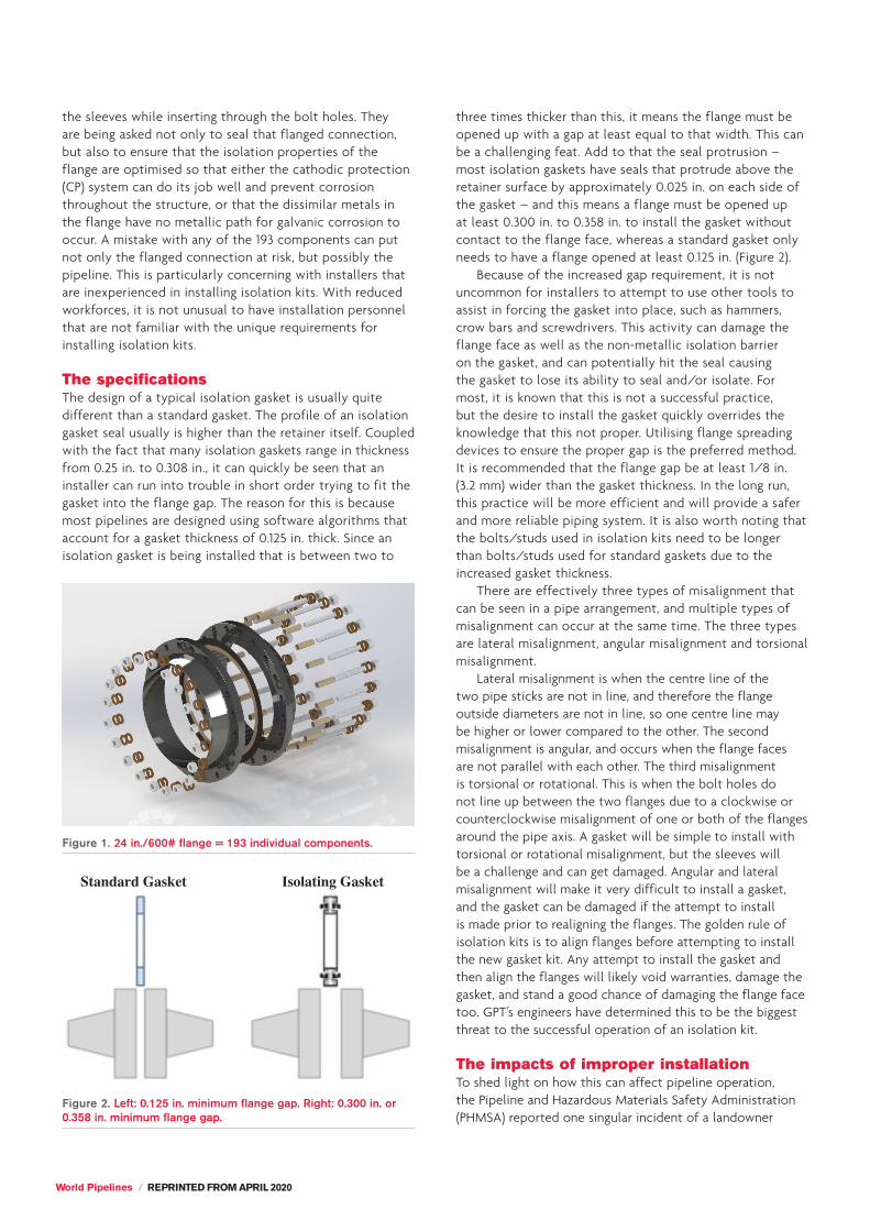
three times thicker than this, it means the flange must be opened up with a gap at least equal to that width. This can be a challenging feat. Add to that the seal protrusion – most isolation gaskets have seals that protrude above the retainer surface by approximately 0.025 in. on each side of the gasket – and this means a flange must be opened up at least 0.300 in. to 0.358 in. to install the gasket without contact to the flange face, whereas a standard gasket only needs to have a flange opened at least 0.125 in. (Figure 2).
Because of the increased gap requirement, it is not uncommon for installers to attempt to use other tools to assist in forcing the gasket into place, such as hammers, crow bars and screwdrivers. This activity can damage the flange face as well as the non-metallic isolation barrier on the gasket, and can potentially hit the seal causing the gasket to lose its ability to seal and/or isolate. For most, it is known that this is not a successful practice, but the desire to install the gasket quickly overrides the knowledge that this not proper. Utilising flange spreading devices to ensure the proper gap is the preferred method. It is recommended that the flange gap be at least 1/8 in. (3.2 mm) wider than the gasket thickness. In the long run, this practice will be more efficient and will provide a safer and more reliable piping system. It is also worth noting that the bolts/studs used in isolation kits need to be longer than bolts/studs used for standard gaskets due to the increased gasket thickness.
There are effectively three types of misalignment that can be seen in a pipe arrangement, and multiple types of misalignment can occur at the same time. The three types are lateral misalignment, angular misalignment and torsional misalignment.
Lateral misalignment is when the centre line of the two pipe sticks are not in line, and therefore the flange outside diameters are not in line, so one centre line may be higher or lower compared to the other. The second misalignment is angular, and occurs when the flange faces are not parallel with each other. The third misalignment is torsional or rotational. This is when the bolt holes do not line up between the two flanges due to a clockwise or counterclockwise misalignment of one or both of the flanges around the pipe axis. A gasket will be simple to install with torsional or rotational misalignment, but the sleeves will be a challenge and can get damaged. Angular and lateral misalignment will make it very difficult to install a gasket, and the gasket can be damaged if the attempt to install is made prior to realigning the flanges. The golden rule of isolation kits is to align flanges before attempting to install the new gasket kit. Any attempt to install the gasket and then align the flanges will likely void warranties, damage the gasket, and stand a good chance of damaging the flange face too. GPT’s engineers have determined this to be the biggest threat to the successful operation of an isolation kit.
The impacts of improper installationTo shed light on how this can affect pipeline operation, the Pipeline and Hazardous Materials Safety Administration (PHMSA) reported one singular incident of a landowner
Figure 2. Left: 0.125 in. minimum flange gap. Right: 0.300 in. or 0.358 in. minimum flange gap.
Standard Gasket Isolating Gasket
REPRINTED FROM APRIL 2020 / World Pipelines
contacting the organisation concerning odours and sheen which were found in a bauer drain. An oil and gas exploration and production (E&P) company initially responded, later notifying another oil and gas E&P company. It was determined that the release was from an oil and gas E&P company tank line, operated by the secondary E&P company. A gasket failure on the tank line was initially identified as the leak source. After completion of the investigation it was determined that the gasket failed due to misalignment during construction. The amount released was calculated based on field investigation data. A boom was initially placed in the bauer drain and recovery wells installed to collect free product. The pipeline company has removed 4500 t of non-hazardous impacted soils from this site. This is an ongoing remediation effort and the PHMSA report includes the estimated final remediation costs – approximately US$40 million. Simply aligning the flanges prior to installation of the gasket would have likely avoided this significant cost.
Once flanges have been aligned and opened up sufficiently to easily install the gasket, the flange face should be cleaned with a wire brush if possible. If there is not enough room for a wire brush (preferably with brass wires), gasket/flange cleaning spray should be sprayed on the flange face and wiped off with a rag. The intent is to remove all potential contaminants from the face of the flange. There have been several installations where the same bolts/studs used for standard gaskets are used for isolation kits, but the bolts/studs do not have enough thread engagement to properly load and seal the gasket. Post installation, there should be at least two threads visible above the nut.
It is also important to note that studs manufactured from threaded rod are preferred over bolts with a smooth shank. The isolation sleeve can be a tight fit over some bolts, and bolts with a smooth shank can cause interference during the installation of the isolation sleeve, causing it to split. Once the isolation sleeve splits, it is a natural place for electrolytes (water – be it rainwater, melting snow or ground water) to
accumulate and negatively affect not only the isolation properties, but also the corrosion rate of the bolts, causing faster corrosion.
Controlling corrosionTo help reduce corrosion around the bolts and to improve compression on the isolation gasket, installers often (correctly) lubricate the nuts/bolts prior to installation. Unfortunately, many installers apply metal-based lubricants to the nuts/bolts for isolation kits. This issue seems readily apparent, but customers often complain that an isolation kit is not isolating, only to find that the user has installed a copper or nickel based anti-stick liberally around the nuts and bolts. This creates an alternate metallic path and therefore does not isolate the flange. It is worth checking for alternate metallic paths if an isolating unit is not isolating – before calling for assistance, make sure you have undertaken a review of alternate metallic paths.
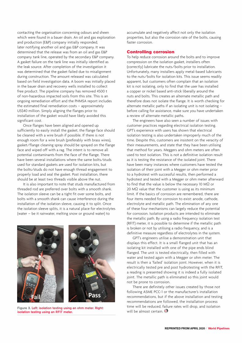
The engineers have also seen a number of issues with customer practices regarding electrical isolation testing. GPT’s experience with users has shown that electrical isolation testing is also undertaken improperly much of the time. Despite this, customers are insistent on the veracity of their measurements, and state that they have been utilising that method for years. Meggers and ohm meters are often used to test isolation. This is not a definitive isolation result as it is testing the resistance of the isolated joint. There have been many instances where customers have tested the isolation of their joint with a Megger or ohm meter prior to a hydrotest with successful results, then performed a hydrotest and tested with a Megger or ohm meter afterward to find that the value is below the necessary 10 MΩ or 20 MΩ value that the customer is using as its minimum limit. If the basics of corrosion are remembered, there are four items needed for corrosion to exist: anode, cathode, electrolyte and metallic path. The elimination of any one of these four mechanisms can largely reduce the potential for corrosion. Isolation products are intended to eliminate the metallic path. By using a radio frequency isolation test (RFIT) meter, it is possible to determine if the metallic path is broken or not by utilising a radio frequency, and is a definitive measure regardless of electrolytes in the system.
GPT’s engineers utilise a demonstration unit that displays this effect. It is a small flanged unit that has an isolating kit installed with one of the pipe ends blind flanged. The unit is tested electrically, then filled with water and tested again with a Megger or ohm meter. The result is then a ‘failed’ isolation joint. However, when it is electrically tested pre and post hydrotesting with the RFIT, a reading is presented showing it is indeed a fully isolated joint. The metallic path is eliminated so this joint would not be prone to corrosion.
There are definitely other issues created by those not following ASME PCC-1 or the manufacturer’s installation recommendations, but if the above installation and testing recommendations are followed, the installation process time will be reduced, failure rates will drop, and isolation will be almost certain.
Figure 3. Left: isolation testing using an ohm meter. Right: isolation testing using an RFIT meter.


![INSTRUCTION MANUAL NON-PRISM TOTAL … SERIES GPT-3102N GPT-3103N GPT-3105N GPT-3107N NON-PRISM TOTAL STATION INSTRUCTION MANUAL 64555 90031 [ROAD]1 FOREWORD Thank you for purchasing](https://img.pdfslide.net/doc/110x75/5bc568dc09d3f264788d04f0/instruction-manual-non-prism-total-series-gpt-3102n-gpt-3103n-gpt-3105n-gpt-3107n.jpg)