Embed Size (px)
Citation preview

822 IEEE TRANSACTIONS ON PLASMA SCIENCE, VOL. 31, NO. 5, OCTOBER 2003
A Two-Dimensional Nonstationary Model of theInitiation of an Explosive Center Beneath the
Plasma of a Vacuum Arc Cathode SpotIgor Vladimirovich Uimanov
Abstract—A numerical two-dimensional nonstationary modelis developed to study initiation of the new explosive center beneaththe plasma of a vacuum arc cathode spot. The process of heatinga cathode surface microprotrusion was simulated numerically.The obtained results show that taking into account the ion impactheating and electric field of the space charge zone near the cathodesurface ensured the “triggering” heat flux power necessary fordeveloping the Joule heating of the microprotrusion followed byan explosion at reasonable values of the ion current and geometricparameters of the microprotrusion.
Index Terms—Cathode spot, explosive electron emission,vacuum arc.
I. INTRODUCTION
NOTWITHSTANDING the fact that both the spark and arcstage of vacuum discharges have been in wide practical
use for many years, interest is increasing in developing theo-retical ideas of physical phenomena responsible for operatingthis type of discharge. As commonly thought, the most impor-tant and active region in a vacuum discharge is the cathode re-gion. It is our belief that the most consistent and comprehen-sive model of a cathode spot is the ecton model [1]. It is basedon recognizing the fundamental role of the microexplosions ofcathode regions that give rise to explosive electron emission ona short time scale. The birth of such an explosive center—anecton—is accompanied by destruction of a cathode surface re-gion (where a crater is then formed), the appearance of plasmain the electrode gap, and the formation of liquid-metal jets anddroplets. An ecton (being an individual cell of a cathode spot)has a comparatively short lifetime (several tens of nanoseconds)[1]. Therefore, an important issue in this theory is the appear-ance of new (secondary) explosive centers to provide self-sus-taining of a vacuum discharge. According to [1], the most prob-able reason for the appearance of a new explosive center imme-diately in the zone of operation or in the vicinity of the previousone is the interaction of a dense plasma with the microprotru-sions present on the cathode surface or with the liquid-metal jetsejected from the crater. These surface microprotrusions can becharacterized by a parameter, equal to the ratio of the micro-protrusion surface area to its base area and defines the current
Manuscript received September 9, 2002; revised May 16, 2003. This workwas supported by the Russian Fundamental Research Foundation under Award02-02-17509.
The author is with the Institute of Electrophysics, 620016 Ekaterinburg,Russia (e-mail: [email protected]).
Digital Object Identifier 10.1109/TPS.2003.818435
density-enhancement factor. An investigation [1] of developingthe explosion of such microprotrusions (in terms of the effect ofenhancement of the current density of the ions moving from theplasma to the cathode and in view of the Joule mechanism of en-ergy absorption) has resulted in concluding that for an explosionto occur within 10 s, it is necessary to have microprotrusionswith 10 at the ion current density 10 A cm . Thiswork is an extension of the previously mentioned model and de-scribes formation of secondary ectons upon the interaction of adense plasma with cathode surface microprotrusions.
In general, the charge particle flow that closes onto a micro-protrusion consists of three components: an ion flow, an electronflow from the plasma, and a flow of emission electrons [2]–[4].Each of these flows carries both an electric charge and an en-ergy flux, forming a space charge zone at short distances fromthe cathode surface and giving rise to an electric fieldat thecathode. In [5], initiation of a cathode spot was investigated forthe ion current , and the electric field at the cathode wasspecified arbitrarily from a “black box” and with an artificiallycreated spatially homogeneous “plasma focus” of radius 10mon a plane cathode. It was shown that the cathode heating by in-cident ions and the enhancement of the electric fieldby theion space charge reduced the critical field at which the processof thermal run-away and overheating below the surface starteddeveloping. It should, however, be noted that the least timesof cathode spot initiation obtained in [5] are longer than 1s.On the other hand, according to the ecton model of a cathodespot [1] and to the experimental data (for example, [6]), thecathode spot phenomena have an essentially nonstationary andcyclic character with the characteristic time scale ranging be-tween 10 and 10 s.
Thus, the goal of this work is to investigate the formation ofsecondary explosive centers upon the plasma interaction of avacuum arc cathode spot with cathode surface microprotrusions.
II. DESCRIPTION OF THEMODEL
A. Problem Statement and Task Geometry
Fig. 1 presents the model geometry of the problem. The shapeof the microprotrusion surface is specified by the Gauss function
, where is the height of the micropro-trusion and specifies the base radius determined for
. We shall further characterize the geometry of a micropro-trusion by a current density-enhancement factor ,where is the surface area of the microprotrusion. For this
0093-3813/03$17.00 © 2003 IEEE

UIMANOV: TWO-DIMENSIONAL NONSTATIONARY MODEL OF THE INITIATION OF AN EXPLOSIVE CENTER 823
Fig. 1. Task geometry and a schematic description of the two-dimensional(2-D) model in a cylindrical symmetry.
model, we assumed that over the cathode surface there was acathode spot plasma with an ion densityand an electron tem-perature at the sheath edge. The quantitiesand werethe problem parameters, and, according to [7], they depend ondistance from the active explosive center. In view of the factthat the width of the space charge layer was much smaller thanthe characteristic dimensions of the microprotrusion, the layerparameters were considered in a one-dimensional (1-D) (local)approximation.
B. Temperature Field
The temperature field in the cathode is calculated with theheat conduction equation
(1)
where is the specific heat at constant pressure,is the thermalconductivity, is the mass density, is the electric conductivity,and is the current density in the cathode. The parameters,and are considered as function of temperature [8].The boundary condition for (1) is given by the resulting heatflux at the cathode surface
(2)
where is the sum of the Nottingham effect , and ion im-pact heating (evaporation cooling does not noticeably affectthe final results). The other boundary conditions are
for
for (3)
where K is the initial homogeneous temperature fieldfor .
C. Joule Heating
The Ohm’s electric potential and current densityin the cathode is determined through the continuity
equation
(4)
with boundary condition at the cathode surface
(5)
Here, is the total current density at the cathodesurface, is the electron emission current density, andisthe current density of the ions moving from the plasma to thecathode. The other boundary conditions are
for
for (6)
D. Plasma-Surface Interaction
To calculate , it is assumed that the ions are treated as mono-energetic particles, entering the sheath edge with Bohm’s ve-locity, and all ions recombine at the cathode surface. Then, theexpression for can be written in the form
(7)
where is the mean ion charge and is the ion mass. Thepower density input into the cathode surface from ion impactheating [3] is , where .Here, is the cathode fall potential, is the averaged ioniza-tion potential, and is the averaged energy per emitted elec-tron. The electron emission characteristics (, ) were cal-culated numerically in the Wentzel–Kramers–Brillouin (WKB)approximation. Because of high temperatures, the temperaturedrift of the chemical potential of the electron system inside thecathode was taken into account (for example, [9]). To calculatethe electric field at the cathode, the Mackeown-like equationwas used, taking into account the electron flow from the spotplasma to the cathode [3], [4], [10]
(8)
where is the cathode surface temperature.In concluding this section, we explain in more detail
how the proposed model takes into account the contribu-tion of the electron flow from the plasma to the cathode.If we assume the velocity distribution of the plasma elec-trons at the sheath edge is a Maxwellian one, we arriveat the statement that only electrons whose velocities are

824 IEEE TRANSACTIONS ON PLASMA SCIENCE, VOL. 31, NO. 5, OCTOBER 2003
TABLE IA SET OF GEOMETRICAL PARAMETERS OF THEMICROPROTRUSIONS AND
THE OBTAINED EXPLOSION DELAY TIME
higher than make a contribution to the currentof the electrons “counterdiffusing” from the quasi-neu-tral plasma to the cathode, . According to [3], we have
. Then, in view of(7), the ratio of this contribution to the ion current density takesthe form . For theparameters used in this work ,we have . Therefore, in (5), we mayneglect the contribution to the total current at the surfaceof the microprotrusion. The small ratio of the electron currentto the current of ions arriving at the cathode from the spotplasma permitted us to ignore as well the energy flux densityof these electrons, , in the general balance of surface heatsources in the boundary condition eqn (2). With the parametersused, we have 10 . Thus, in the caseunder consideration, contributions of and to the currentand energy balance at the cathode surface can be neglected.At the same time, it should be stressed that the effect of theelectron flow from the plasma to the cathode was essential incalculating characteristics of the space charge sheath, (8). If wetake account of the effect of the space charge of this flow, wesee that noticeably decreases. This resulted in a substantialchange in the development rate of thermal instability becauseof the strong dependence of the emission characteristics on.
III. RESULTS
Computations were performed for a copper cathode with thefollowing arc parameters: V, eV, .For the initial conditions of the problem, plasma characteris-tics at the sheath edge and microprotrusion geometry( ) were specified. Computations were performed for a set ofgeometrical parameters of the microprotrusions, shown in theTable I.
The computation was performed until the maximum temper-ature in the protrusion reached a critical temperature
K. As this happened, the model became inoperative, andthe process went to the explosive phase of development of anecton.
Fig. 2 shows results of computation for the temperature fieldand the spatial distribution of the current density modulus. The
Fig. 2. Space distribution of temperature and current density modulus: a)�t = 0:23 � ns; b)�t = 1:9 ns; and c)�t = 6:2 � ns. Calculated parameters:n = 10 m T = 2 eV (j = 5:6 � 10 A/m ); � = 4.
simulation showed that the heating of a microprotrusion canbe subdivided by convention into two stages. At the first stage[Fig. 2(a)], where the cathode was still comparatively cold, thesurface heating due to ion impact prevailed. In this case, the mi-croprotrusion behaved as if it were a collecting thermal lens.The Joule heating at this stage was inessential. As the tempera-ture reached 3500 K K, the emission current densityincreased substantially, and intense surface cooling began andwas associated with the onset of the second stage of heating,see Fig. 2(b). At this point, the current density maximum was inthe bulk of the microprotrusion. and, hence, this was the region
UIMANOV: TWO-DIMENSIONAL NONSTATIONARY MODEL OF THE INITIATION OF AN EXPLOSIVE CENTER 825
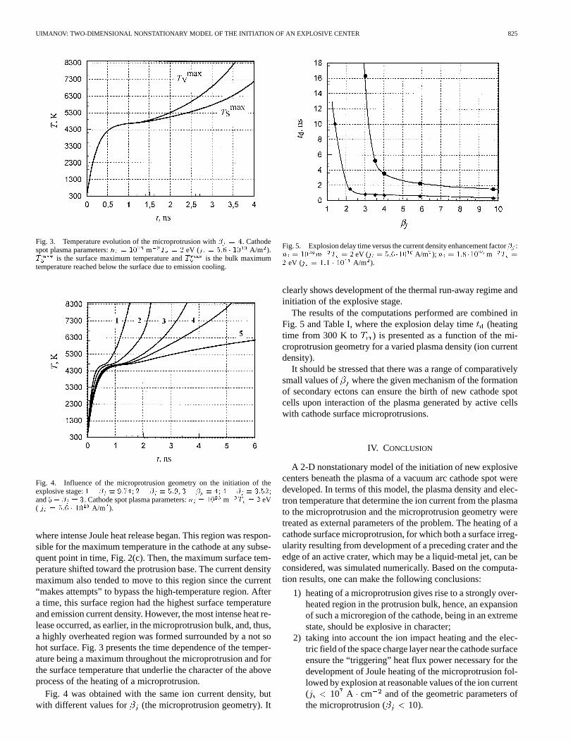
Fig. 3. Temperature evolution of the microprotrusion with� = 4. Cathodespot plasma parameters:n = 10 m T = 2 eV (j = 5:6 � 10 A/m ).T is the surface maximum temperature andT is the bulk maximumtemperature reached below the surface due to emission cooling.
Fig. 4. Influence of the microprotrusion geometry on the initiation of theexplosive stage:1� � = 9:74; 2� � = 5:9, 3� � = 4; 4� � = 3:52;and5� � = 3. Cathode spot plasma parameters:n = 10 m T = 2 eV( j = 5:6 � 10 A/m ).
where intense Joule heat release began. This region was respon-sible for the maximum temperature in the cathode at any subse-quent point in time, Fig. 2(c). Then, the maximum surface tem-perature shifted toward the protrusion base. The current densitymaximum also tended to move to this region since the current“makes attempts” to bypass the high-temperature region. Aftera time, this surface region had the highest surface temperatureand emission current density. However, the most intense heat re-lease occurred, as earlier, in the microprotrusion bulk, and, thus,a highly overheated region was formed surrounded by a not sohot surface. Fig. 3 presents the time dependence of the temper-ature being a maximum throughout the microprotrusion and forthe surface temperature that underlie the character of the aboveprocess of the heating of a microprotrusion.
Fig. 4 was obtained with the same ion current density, butwith different values for (the microprotrusion geometry). It
Fig. 5. Explosion delay time versus the current density enhancement factor� :n = 10 m T = 2 eV (j = 5:6�10 A/m ); n = 1:8 �10 m T =
2 eV (j = 1:1 � 10 A/m ).
clearly shows development of the thermal run-away regime andinitiation of the explosive stage.
The results of the computations performed are combined inFig. 5 and Table I, where the explosion delay time(heatingtime from 300 K to ) is presented as a function of the mi-croprotrusion geometry for a varied plasma density (ion currentdensity).
It should be stressed that there was a range of comparativelysmall values of where the given mechanism of the formationof secondary ectons can ensure the birth of new cathode spotcells upon interaction of the plasma generated by active cellswith cathode surface microprotrusions.
IV. CONCLUSION
A 2-D nonstationary model of the initiation of new explosivecenters beneath the plasma of a vacuum arc cathode spot weredeveloped. In terms of this model, the plasma density and elec-tron temperature that determine the ion current from the plasmato the microprotrusion and the microprotrusion geometry weretreated as external parameters of the problem. The heating of acathode surface microprotrusion, for which both a surface irreg-ularity resulting from development of a preceding crater and theedge of an active crater, which may be a liquid-metal jet, can beconsidered, was simulated numerically. Based on the computa-tion results, one can make the following conclusions:
1) heating of a microprotrusion gives rise to a strongly over-heated region in the protrusion bulk, hence, an expansionof such a microregion of the cathode, being in an extremestate, should be explosive in character;
2) taking into account the ion impact heating and the elec-tric field of the space charge layer near the cathode surfaceensure the “triggering” heat flux power necessary for thedevelopment of Joule heating of the microprotrusion fol-lowed by explosion at reasonable values of the ion current( 10 A cm and of the geometric parameters ofthe microprotrusion ( 10).

826 IEEE TRANSACTIONS ON PLASMA SCIENCE, VOL. 31, NO. 5, OCTOBER 2003
ACKNOWLEDGMENT
The author would like to thank G. A. Mesyats for providingencouragement and stimulating discussions.
REFERENCES
[1] G. A. Mesyats,Cathode Phenomena in Vacuum Discharge: The Break-down, the Spark and the Arc. Moscow, Russia: Nauka, 2000.
[2] G. Ecker, “Theoretical aspects of the vacuum arc,” inVacuum Arc,Theory and Aplication, J. M. Lafferty, Ed. New York: Wiley, 1980,pp. 228–320.
[3] E. Hantzscheet al., “Theories of cathode spots,” inHandbook of VacuumArc Science and Technology, R. L. Boxmanet al., Eds. Park Ridge, NJ:Noyes, 1995, pp. 151–208.
[4] I. I. Beilis et al., “Theoretical modeling of cathode spot phenomena,” inHandbook of Vacuum Arc Science and Technology, R. L. Boxmanet al.,Eds. Park Ridge, NJ: Noyes, 1995, pp. 208–256.
[5] Z. J. He and R. Haug, “Cathode spot initiation in different external con-ditions,” J. Phys. D, Appl. Phys., vol. 30, no. 4, pp. 603–613, Feb. 1997.
[6] B. Juttner, “Cathode spots of electric arcs,”J. Phys. D, Appl. Phys., vol.34, no. 17, pp. R103–R123, Sept. 2001.
[7] D. L. Shmelev and E. A. Litvinov, “Computer simulation of ecton invacuum arc,” inProc. 18th Int. Symp. Discharges and Electrical Insu-lation in Vacuum, vol. 1, Eindhoven, The Netherlands, Aug. 1998, pp.73–75.
[8] V. E. Zinoviev,Thermal properties of metals at high temperatures. Ref-erence Book(in Russian). Moscow, Russia: Metallurgia, 1989.
[9] T. Klein, J. Paulini, and G. Simon, “Time-resolved description ofcathode spot development in vacuum arcs,”J. Phys. D, Appl. Phys., vol.27, no. 9, pp. 1914–1921, Sept. 1994.
[10] S. S. Mackeown, “The cathode drop in an electric arc,”Phys. Rev., vol.34, no. 4, pp. 611–614, Aug. 1929.
Igor Vladimirovich Uimanov was born in Novocuz-nesk, U.S.S.R. (now Russia), on January 23, 1967.He received the M.S. degree in physics from the UralState University, Ural, Russia, in 1992 and the Ph.D.degree from the Institute of Electrophysics, RussianAcademy of Sciences (RAS), Ekaterinburg, in 2001.
He has been with the Institute of Electrophysics,RAS, since 1992. He is currently the Deputy Headof the Laboratory IEP. His research interests includefield emission and vacuum discharges.