Embed Size (px)
Citation preview
DUNEDIN NEW ZEALAND
A Viewpoint-Based Framework for Discussing the Use of Multiple Modelling Representations
Nigel Stanger
The Information Science Discussion Paper Series
Number 2000/09
April 2000 ISSN 1177-455X

University of Otago
Department of Information Science
The Department of Information Science is one of six departments that make up the Division of Com-merce at the University of Otago. The department offers courses of study leading to a major in Information Science within the BCom, BA and BSc degrees. In addition to undergraduate teaching, the department is also strongly involved in postgraduate research programmes leading to MCom, MA, MSc and PhD degrees. Research projects in spatial information processing, connectionist-based infor-mation systems, software engineering and software development, information engineering and database, software metrics, distributed information systems, multimedia information systems and in-formation systems security are particularly well supported. The views expressed in this paper are not necessarily those of the department as a whole. The accuracy of the information presented in this paper is the sole responsibility of the authors.
Copyright Copyright remains with the authors. Permission to copy for research or teaching purposes is granted on the condition that the authors and the Series are given due acknowledgment. Reproduction in any form for purposes other than research or teaching is forbidden unless prior written permission has been ob-tained from the authors.
Correspondence This paper represents work to date and may not necessarily form the basis for the authors’ final conclu-sions relating to this topic. It is likely, however, that the paper will appear in some form in a journal or in conference proceedings in the near future. The authors would be pleased to receive correspondence in connection with any of the issues raised in this paper, or for subsequent publication details. Please write directly to the authors at the address provided below. (Details of final journal/conference publica-tion venues for these papers are also provided on the Department’s publications web pages: http://www.otago.ac.nz/informationscience/pubs/publications.html). Any other correspondence con-cerning the Series should be sent to the DPS Coordinator.
Department of Information Science University of Otago P O Box 56 Dunedin NEW ZEALAND Fax: +64 3 479 8311 email: [email protected] www: http://www.otago.ac.nz/informationscience/

A Viewpoint-Based Framework for Discussing theUse of Multiple Modelling Representations
Nigel Stanger
University of Otago, Dunedin, New [email protected]
AbstractWhen modelling a real-world phenomenon, it can often be useful to have multi-
ple descriptions of the phenomenon, each expressed using a different modelling ap-proach or representation. Different representations such as entity-relationship mod-elling, data flow modelling and use case modelling allow analysts to describe differ-ent aspects of real-world phenomena, thus providing a more thorough understand-ing than if a single representation were used. Researchers working with multiplerepresentations have approached the problem from many different fields, resultingin a diverse and potentially confusing set of terminologies. In this paper is describeda viewpoint-based framework for discussing the use of multiple modelling repre-sentations to describe real-world phenomena. This framework provides a consistentand integrated terminology for researchers working with multiple representations.An abstract notation is also defined for expressing concepts within the framework.
1 Introduction
In this paper is described a framework for discussing the use of multiple modellingapproaches or representations to describe a real-world phenomenon. This frameworkis derived from work on viewpoint-oriented design, and provides a consistent and inte-grated terminology for researchers working with multiple modelling representations.An abstract notation for expressing various concepts within the framework is also de-fined.
Why is it useful to describe the same phenomenon using multiple modelling rep-resentations? There are several reasons, such the ability to provide a more completedescription of the phenomenon in question, and because some representations are bet-ter suited to particular problems than others. The use of multiple representations andassociated issues are discussed in Section 2.
The framework described in this paper is primarily derived from earlier work in thearea of viewpoint-oriented design methods. The basic concepts of viewpoint-orienteddesign methods are introduced in Section 3, and a lack of clarity is identified with re-spect to the definitions of some fundamental concepts (in particular, the meaning of theterm ‘representation’).
The author’s framework arose out of the need to clarify the definitions of variousterms and also to integrate and simplify the potentially confusing range of terminolo-gies developed by other authors. The framework is discussed in Section 4. In particular,
1
the terms ‘representation’, ‘technique’ and ‘scheme’ are clarified, and the new terms‘description’, ‘construct’ and ‘element’ are defined.
The author has also developed an abstract notation for expressing various frame-work concepts in a concise manner. This notation is defined in Section 5.
The paper is concluded in Section 6.
2 Using multiple representations to describe a phenome-non
There are many different types of information to be considered when designing an in-formation system, and a wide variety of modelling approaches and notations have beendeveloped to capture these different types of information: entity-relationship diagrams(ERDs), data flow diagrams (DFDs), use case diagrams, the relational model, formalmethods and so on. Problems can arise when useful information is omitted from a de-sign. Consider an information system whose data structures are designed using entity-relationship diagrams and are implemented in a relational database. Data entry formsderived from these models are built using a rapid application development tool. Gooddesign practices are followed throughout, yet the finished application is difficult to use.Some of the commonly used data entry forms have multiple states, but the transitionsbetween these states are unclear to users because state information was not included inthe system design.
While this is a purely theoretical example, it serves to illustrate an important point.Information systems are typically built to handle the data processing requirements ofsome real-world phenomenon. Such real-world phenomena may often be too complexto describe using a single modelling approach, or representation. This is supported bythe plethora of different representations that currently exist [26, 42], including thosethat model the structure of data (such as entity-relationship modelling), and those thatmodel how data move around a system (such as data flow diagrams). This implies thatin order to completely model a phenomenon, multiple descriptions of the phenomenonare required, expressed using different representations.
Using multiple representations to describe a phenomenon is also important in otherways:
• If multiple developers are working on a project, each may prefer or be requiredto use a different representation to describe their particular part of the project [2].Meyers [30] also notes that it can be very useful to simultaneously view a systemin several different ways when multiple people are working on the system.
• Particular subproblems may be better described using some representations thanothers [15].
• Multiple representations are important when integrating heterogeneous data sour-ces to form a federated or distributed system [2], as each data source may poten-tially use a different logical data model.
The idea of using multiple representations to model a phenomenon is not new.Grundy et al. have been examining the issues associated with building multi-viewediting systems and integrated software development environments for many years
2

[20, 21, 23], with emphasis on the issue of maintaining consistency between differ-ent views or descriptions of the same phenomenon [22, 24]. Grundy’s work was de-rived from earlier work on multi-view editing systems for software engineering, suchas FIELD [35] and Zeus [5].
Atzeni and Torlone [3] suggested the idea of translating between different represen-tations as a means of facilitating the use of multiple representations. They proposed aformal model based on lattice theory [1] that allowed them to express many differentdata modelling approaches using primitive constructs of a single underlying represen-tation.
Su et al. [40, 41] approached the use of multiple representations from the point ofview of integrating heterogeneous data sources in order to build federated and dis-tributed databases. Their approach is similar in many respects to that taken by Atzeniand Torlone, except that the underlying representation is object-oriented rather thanmathematically based.
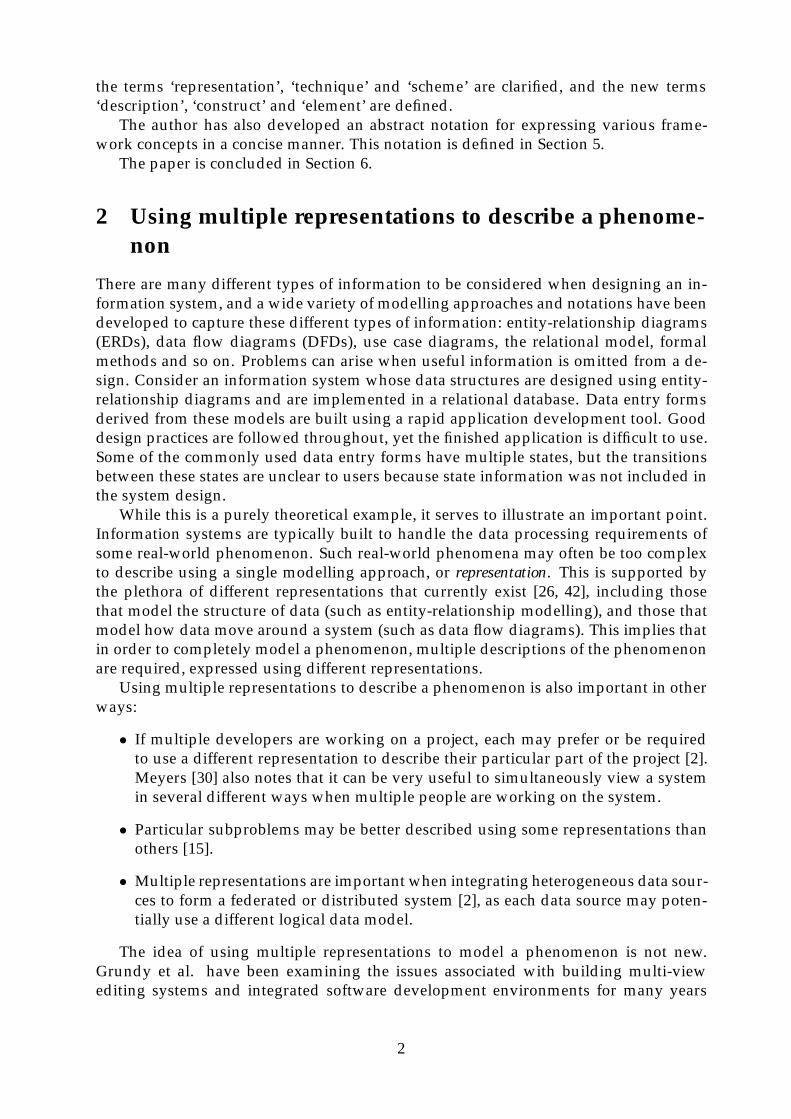
All three groups developed their work independently of each other over a similartime period (1991–94), and each approached the use of multiple modelling represen-tations from a different starting point. This has resulted in a diverse and potentiallyconfusing set of terminologies (see Table 1). A single integrated terminology wouldreduce this potential for confusion.
In addition to the three groups outlined above, viewpoint researchers first suggestedusing multiple representations to describe viewpoints over a decade ago [17]. A view-point is effectively a formalisation of the perceptions of stakeholders with respect tosome real-world phenomenon. Since we are dealing with the use of multiple represen-tations to describe real-world phenomena, viewpoints should provide a useful frame-work within which to discuss such use [39]. The author’s framework will be describedin Section 4, but first the basic concepts of viewpoint-oriented methods must be defined.
3 Viewpoint concepts
A viewpoint can be thought of as a formalisation of the perceptions of a stakeholdergroup with respect to some real-world phenomenon that is being modelled. The firstviewpoint-oriented approach (Mullery’s CORE method) was introduced in 1979 [32],but the concept of a viewpoint was not formalised until ten years later [17].
Viewpoint-oriented methods were originally developed to assist with requirementsdefinition in a software engineering environment [32], and subsequent research has fol-lowed a similar direction [15, 16, 28, 33]. The focus of the author’s research has beenon how to facilitate the use of multiple representations to describe a single viewpoint[38, 39].
In Fig. 1 are shown the relationships between the concepts of viewpoint-orientedmethods. This initial framework was derived by the author [39] from the work of Finkel-stein et al. [17], Easterbrook [15] and Darke and Shanks [11]. Their terminologies arealso summarised in Table 1.
3.1 Perspectives and viewpoints
Easterbrook [15] defines a perspective as “a description of an area of knowledge whichhas internal consistency and an identifiable focus of attention”. During the require-ments definition phase of systems analysis, developers may encounter many different
3
Tabl
e1:
Com
pari
son
ofvi
ewpo
int/
repr
esen
tati
onte
rmin
olog
ies
Cor
resp
ond
ing
term
use
db
y:Te
rmu
sed
Fin
kel
stei
nE
aste
rbro
okD
ark
e&
Gru
nd
yA
tzen
i&S
uet
al.
by
the
auth
orM
ean
ing
Exa
mp
le[1
7][1
5]S
han
ks
[11]
etal
.[21
]To
rlon
e[3
][4
1]
pers
pect
ive
Ad
escr
ipti
onof
are
al-w
orld
phen
omen
onth
atha
sin
ter-
nalc
onsi
sten
cyan
dan
iden
ti-
fiabl
efo
cus.
––
pers
pect
ive
pers
pect
ive
––
–
view
poin
tT
hefo
rmat
ted
des
crip
tion
ofa
pers
pect
ive.
–V
iew
Poin
tvi
ewpo
int
view
poin
t–
––
tech
niqu
eA
colle
ctio
nof
abst
ract
con-
stru
cts
that
form
am
odel
ling
‘met
hod
’.
rela
tion
alm
odel
styl
e
styl
e
tech
niqu
e–
mod
el
dat
am
odel
sche
me
Aco
llect
ion
ofco
ncre
teco
n-st
ruct
sth
atfo
rma
mod
ellin
g‘n
otat
ion’
.
SQL
/92
sche
me
–
repr
esen
tati
onT
heco
mbi
nati
onof
apa
rtic
u-la
rte
chni
que
and
sche
me.
rela
tion
alm
odel
+SQ
L/
92re
pres
enta
tion
repr
esen
tati
on
des
crip
tion
An
inst
anti
atio
nof
are
pre-
sent
atio
n.SQ
L/
92sc
hem
asp
ecifi
cati
ond
escr
ipti
on–
view
sche
me
sche
ma
cons
truc
tT
heba
sic
unit
ofa
repr
esen
ta-
tion
.a
rela
tion
––
––
cons
truc
tcl
assa
elem
ent
An
inst
anti
atio
nof
aco
nstr
uct
wit
hin
apa
rtic
ular
des
crip
-ti
on.
Sta
ffta
ble
––
–co
mpo
nent
vari
esb
obje
ct
Not
eson
Tab
le1:
aA
lso
‘con
stru
ct’.
bTe
rms
used
incl
ude
‘com
pone
nt’,
‘ele
men
t’an
d‘c
once
pt’.
‘–’i
ndic
ates
that
ate
rmis
notu
sed
byth
atau
thor
.
4

Rep’n Rep’n
Technique
Scheme
Technique
Scheme
Technique
Scheme
Representation Representation Representation
Information system design environment using multiple modelling representations
Real-world phenomenon
formalised as a
using one or moreViewpoint integration
viewed from several
Perspective Perspective Perspective
Viewpoint Viewpoint Viewpoint
Scheme Scheme
Technique
Figure 1: Relationship between perspectives, viewpoints and representations
perspectives on the problem being modelled. Perspectives may overlap and/or conflictwith each other in various ways.
Finkelstein et al. [17] describe a viewpoint as comprising the following parts:
• “a style, the representation scheme in which the ViewPoint [sic] expresses whatit can see (examples of styles are data flow analysis, entity-relationship-attributemodelling, Petri nets, equational logic, and so on);
• a domain defines which part of the ‘world’ delineated in the style (given that thestyle defines a structured representation) can be seen by the ViewPoint (for exam-ple, a lift-control system would include domains such as user, lift and controller);
• a specification, the statements expressed in the ViewPoint’s style describing partic-ular domains;
• a work plan, how and in what circumstances the contents of the specification canbe changed; [and]
• a work record, an account of the current state of the development.”
Easterbrook [15] simplifies this description by defining a viewpoint as “the format-ted representation of a perspective”, and notes that a perspective is a “more abstractversion of a viewpoint”. In effect, a viewpoint is the formalisation of a particular per-spective, so there is a one-to-one correspondence between a viewpoint and the perspec-tive it formalises, as illustrated in Fig. 1.
5

The term ‘viewpoint’ is very similar to the term ‘view’ as used in multi-view editingsystems [5, 20, 27, 30]. These terms refer to different concepts, however: a ‘view’ is moreakin to the concept of a description, which will be introduced in Section 4. The similarityof the two terms has led to some confusion: the terms ‘viewpoint’ and ‘view’ have beenused interchangeably in the past [27].
Darke and Shanks [11] define two main types of viewpoint:
1. user viewpoints that capture “the perceptions and domain knowledge of a particu-lar user group, reflecting the particular portion of the application domain relevantto that group”; and
2. developer viewpoints that capture “the perceptions, domain knowledge and mod-elling perspective relevant to a systems analyst or other developer responsible forproducing some component of the requirements specification”.
Since a viewpoint is the formalisation of a perspective, some form of model is re-quired to provide the formalised structure. The concept of a representation provides this.
3.2 Representations
Darke and Shanks [10] note that viewpoints may be described using different repre-sentation techniques, within each of which there may be available a number of repre-sentation schemes. Neither Darke and Shanks nor Finkelstein et al. [17] clearly definethe terms ‘representation’, ‘technique’ or ‘scheme’; rather, they introduce each term bymeans of examples. This has led to some confusion in the use of this terminology. Darkeand Shanks use the terms ‘representation’ and ‘representation technique’ interchange-ably, while Finkelstein et al., as can be seen in their definition of a ‘style’, use the term‘representation scheme’ in a similar way.
The intent appears to be that a representation should be thought of as a structuredmodelling approach that can be used to describe the content of a viewpoint. In orderto clarify the confusion in terminology, the author has refined this informal definitionand defined a representation as the combination of a particular technique and schemeto describe a viewpoint. This will be discussed further in Section 4.
Darke and Shanks [11] group representations into three general categories:
1. informal representations that form unstructured descriptions, often expressed us-ing natural language or simple diagrams;
2. semi-formal representations that form structured descriptions, such as entity-rela-tionship modelling or data flow diagrams; and
3. formal representations that form structured descriptions and include a set of oper-ators for processing these descriptions, such as the relational model or logic-basedmodels.
Unlike informal representations, which are often ill-defined, inconsistent and am-biguous, semi-formal and formal representations are well-defined, consistent and gen-erally unambiguous. A key feature of formal representations that is lacking in semi-formal representations is the inclusion of operators that allow assertions to be madeabout the viewpoints being described; Greenspan et al. [19] describe this as the abilityto ‘reason’ about representations. User viewpoints are typically defined using informal
6

representations, whereas developer viewpoints are typically defined using semi-formalor formal representations.
Finkelstein et al. [17] first mooted the idea of using multiple representations to de-scribe a viewpoint in 1989, but there has been surprisingly little work in this area sincethen. Darke and Shanks [12] found in a review of twelve different viewpoint develop-ment approaches that only two supported multiple representations to describe a singleviewpoint: the Soft Systems methodology [7] and Scenario Analysis [25], both of whichare user viewpoint approaches rather than developer viewpoint approaches.
The author’s own research [38, 39] has followed the approach of using multiple rep-resentations to describe a single developer viewpoint, and uses an integrated terminol-ogy framework derived from viewpoint-oriented methods. This framework will nowbe described.
4 The viewpoint framework for discussing the use of mul-tiple modelling representations
Looking at Table 1, there is an obvious dichotomy between the three viewpoint termi-nologies on the left and the three multiple-view terminologies on the right. The view-point terminologies deal primarily with ‘high level’ concepts and ignore how repre-sentations are internally structured; conversely, the multiple-view terminologies dealprimarily with constructs within representations and ignore higher-level structure. Thetwo sets of terminology are clearly related, yet the only real overlap between them is atthe representation level.
There are also many synonyms in the terminologies presented in Table 1, for exam-ple, the terms ‘style’, ‘representation’, ‘model’ and ‘data model’ are all used to referto similar concepts. Conversely, the term ‘scheme’ is used to refer to two completelydifferent concepts. Such variation can lead to confusion, so there is a definite need todevelop a consistent and integrated terminology framework.
The initial framework shown in Fig. 1 provides a good basis for extension, but theauthor has identified some confusion over the exact definitions of the terms ‘represen-tation’, ‘technique’ and ‘scheme’. The author has addressed this confusion by clearlydefining these terms, and has extended the original framework with the concepts ofdescriptions, constructs of representations and elements of descriptions (see Fig. 2).
4.1 Representations
Informally, a data modelling representation can be thought of as comprising two mainparts:
1. a generic part that specifies the generic constructs that may be used to describe aviewpoint, such as entities, relations, and so on; which then determines
2. a specialised part that specifies the constructs peculiar to the representation, alongwith their visual appearance or notation, such as boxes for entities, SQL CREATETABLE statements for relations, and so on.
Finkelstein et al.’s [17] use of the term ‘style’ does not clearly distinguish betweenthese two parts; conversely, the ‘techniques’ and ‘schemes’ of Darke and Shanks [10]
7

Description Description Description
Information system design environment using multiple modelling representations
Real-world phenomenon
formalised as a
viewed from several
Perspective Perspective Perspective
Viewpoint Viewpoint
technique
scheme
Representation Representation Representation
Process
Data store
Data flowWeak entity
Attribute
Relationship
Attribute
Dependency
Attribute set
emp_noEMP_NO
A+Bcreate table staff ...
emp_no char(7)
primary key (emp_no)
Process modelling
G&S DFD Smith FDD
Functional Dep.
Martin ERD
ERM
SQL QUEL
{{
Rep’n Rep’n
TableAttribute
Primary key
Relational
Description
Viewpoint
described by one or more
expressed using expressed usingexpressed usingexpressed using“s
peci
alis
ed”
cons
truc
ts“g
ener
ic”
cons
truc
ts
elem
ents
...create table result( result_id integer, element_id integer not null, student_id char(7) not null, staff_id char(8) not null, date_submitted date, date_marked date, raw_mark smallint, comments char(500), primary key (result_id), foreign key (element_id) references element, foreign key (student_id) references student, foreign key (staff_id) references staff); ...
Viewpoint integration
a
Student
P1
Markassignment
D1 Staff
Receivedassignments
P2
Returnresults
D3 Element
D4 Assignment
D2 Student
assignment
staff IDstudent ID
marking details
results
resultsresults
Student
Assignment AssessmentElementStaff
marks
CRITERION_NAME
ADJUSTMENT_NO
ASSIGN_ID
DATE_SUBMITTED
DATE_MARKEDRAW_MARK
COMMENTS
MARK + COMMENTS
PARENT_ANSWER
REASON +AMOUNT
2
ANSWER_IDMARK +
COMMENTS
NAME +TOTAL_MARK +
PERCENT + DUE_DATE +LATE_PENALTY
ELEMENT_ID
2
NUMBER + MARKS +GUIDELINES
PARENT_QUESTION 1
QUESTION_ID 1
STAFF_ID
STUDENT_ID
NAME +PASSWORD
NAME +PASSWORD
Figure 2: The extended terminology framework
8

match these two parts well. It is therefore proposed to use the term technique to refer tothe generic part of a representation, and the term scheme to refer to the specialised partof a representation. In practical terms, a technique can be thought of as a modelling ‘ap-proach’, such as the entity-relationship approach or the relational model, and a schemecan be thought of as a particular ‘notation’ within that approach, such as a particularentity-relationship notation or relational calculus. Another way to think of this is that ascheme is an ‘instantiation’ of a particular technique.
A representation can thus be defined as the combination of a particular techniquewith a particular scheme, as illustrated in Fig. 2. In general, a technique may haveone or more associated schemes, but each combination of a technique and a schemeforms a distinct representation. For example, the relational model is a technique, withSQL and QUEL as two possible schemes, but the combinations (Relational , SQL)1 and(Relational ,QUEL) form two distinct representations, as shown in Fig. 3. Similarly, theentity-relationship approach (E -R) is a technique, with ERDMartin and ERDChen as twopossible schemes. The combinations (E -R,ERDMartin) and (E -R,ERDChen) again formtwo distinct representations.
Martin Chen
Entity-relationship
SQL QUEL
Relational
Representation Representation
Figure 3: Multiple schemes within a technique
It is expected that a technique will not attempt to specify all possible concepts for allpossible schemes within that technique. Rather, a technique defines the ‘base’ model,which is then specialised and extended by schemes to form a representation. This im-plies that a scheme may provide new constructs to a representation that have no directanalogue in the technique. For example, the relational technique [9] does not includegeneral constraints, but they are an important feature of the relational scheme SQL/92[14]. Similarly, type hierarchies are not part of the base E-R technique [8], but they doappear in some E-R schemes.
4.2 Descriptions
Representations are an abstract concept, so they must be instantiated in some way inorder to describe the content of a viewpoint. One way to view the instantiation of a rep-resentation is as a set of ‘statements’ that describe a viewpoint or some subset thereof.Finkelstein et al. [17] refer to this as a ‘specification’ or ‘description’; Easterbrook [15]also refers to this concept as a description. The author has adopted the term ‘descrip-tion’ as it emphasises the idea that they are used to describe a viewpoint.
A viewpoint is thus specified by a set of descriptions, each expressed using somerepresentation, as shown in Fig. 2. Each description may describe either the wholeviewpoint or some subset of the viewpoint; this is analogous to the concept of a ‘view’as used in multi-view editing systems [5, 20, 27, 30]. For example, a developer viewpointmight be specified by union of the following four descriptions:
1In practice, the many dialects of SQL will form many different representations. This has been ignoredhere in the interests of clarity.
9

1. an object class description expressed using Unified Modelling Language (UML)class diagram notation [31];
2. a functional dependency description expressed using Smith functional depen-dency diagram notation [36, 37];
3. a relational description expressed using SQL/92; and
4. a data flow description expressed using Gane & Sarson data flow diagram nota-tion [18].
Similarly, a user viewpoint might be specified by the union of a natural languagedescription and a collection of diagrammatic descriptions. Descriptions may be dis-tinct from each other, or they may overlap in a manner similar to viewpoints. Suchredundancy can be useful in exposing conflicts both between descriptions and betweenviewpoints [15].
4.3 Constructs and elements
Every representation comprises a collection of constructs. These may be divided intogeneric constructs associated with the technique (technique-level constructs) and spe-cialised constructs associated with the scheme (scheme-level constructs), as shown inFig. 2. The nature of a construct is defined by its properties, which include both its rela-tionships with other constructs, and its attributes, such as name, domain or cardinality2.For instance, as illustrated in Fig. 4, a data store in a data flow diagram might have theattributes name (the name of the data store), label and fields (a list of data fields in the datastore). The flows relationship specifies an association between the data store constructand a list of data flow constructs.
purchase_idpurchase_datepurchase_pricecustomer_nosalesrep_idregistration
D1 Purchase
fields
flowsname
label
Figure 4: Properties of a construct
In the same way that a description is an instantiation of a representation, an element isan instantiation of a construct; elements are combined to build descriptions. Examplesof constructs include object classes, processes and attributes; elements corresponding tothese constructs could be Order, Generate invoice and address.
2The terms ‘property’, ‘attribute’ and ‘relationship’ come from the Object Data Management Group’sobject model [6].
10

5 A notation to express representations, descriptions, con-structs and elements
It can be cumbersome to discuss aspects of representations and descriptions using nat-ural language, for example, ‘the Staff regular entity element of the description D1 (ex-pressed using Martin entity-relationship notation) of the managers’ viewpoint’. The au-thor has therefore developed a concise abstract notation for expressing representations,descriptions, constructs of representations and elements of descriptions. This notationis modelled in part on the data transfer notation of Pascoe and Penny [34]. Using thenotation, the statement above could be expressed as:
D1(Vmgrs,E -R,ERDMartin) [staff : REGULARENTITY] .
The notation is summarised in Table 2. The author has defined additional notationsfor expressing translations of descriptions from one representation to another [38]. Forexample, the expression:
D1(V,FuncDep,FDDSmith)→ D2(V,E -R,ERDMartin)
denotes the translation within viewpoint V of a functional dependency description D1
into an entity-relationship description D2. Such additions are beyond the scope of thispaper, however; only the base notation is discussed here.
5.1 Description and representation notation
The notation D(V, T, S) denotes that description D of viewpoint V is expressed usingconstructs of technique T and scheme S (this may be abbreviated to D when V , T andS are clear). Thus, D1(Vp,E -R,ERDMartin) denotes a description D1 of the viewpointVp that is expressed using constructs of the entity-relationship technique (E -R) and theMartin ERD scheme (ERDMartin) [29].
The notation R(T, S) denotes a representation R that comprises a collection of con-structs defined by the combination of technique T and scheme S (this may be abbrevi-ated toRwhen T and S are clear). Thus,Re(E -R,ERDMartin) denotes the representationRe formed by combining the constructs of the entity-relationship technique (E -R) withthe Martin ERD scheme (ERDMartin). This notation is similar to that used by Finkelsteinet al. to describe viewpoint styles [17], but focuses on the technique and scheme usedrather than individual constructs within a representation.
The combination of technique T and scheme S forms the representationR(T, S), so itis also possible to denote the descriptionD(V, T, S) byD(V,R(T, S)), or simplyD(V,R).Thus, the notations D1(Vp,E -R, ERDMartin), D1(Vp,Re(E -R,ERDMartin)) and D1(Vp,Re)are equivalent. The first form is preferred by the author as it clearly distinguishes be-tween the technique and scheme.
Representations may differ in both the technique and scheme used, or they mayshare the same technique and differ only in the scheme. Thus, two descriptions D1 andD2 of viewpoint V that are expressed using representations having different schemesSi and Sj are denoted by D1(V, T, Si) and D2(V, T, Sj) respectively. Similarly, two de-scriptions D3 and D4 of viewpoint V that are expressed using representations havingdifferent techniques (Tk, Tl) and schemes (Sm, Sn) are denoted by D3(V, Tk, Sm) andD4(V, Tl, Sn) respectively.
11

Table 2: Summary of the abstract notationNotation Associated term Definition
V Viewpoint A formatted expression of a perspec-tive on a real-world phenomenon.
T Technique A collection of generic constructsthat form a modelling ‘method’, forexample, the relational model or ob-ject modelling.
S Scheme A collection of specialised constructsthat form a modelling ‘notation’, forexample, SQL/92 or UML class dia-gram notation.
R(T, S) orR Representation Representation R comprises con-structs defined by the combination oftechnique T and scheme S.
D(V, T, S) or D Description Description D of viewpoint V isexpressed using constructs of tech-nique T & scheme S.
R(T, S) [CON],R [CON], or CON
Construct of arepresentation
CON specifies a construct of repre-sentationR(T, S).
D(V, T, S) [e : CON],D [e : CON], or D [e]
Element of adescription
e specifies an element (instantiatedfrom construct CON) of descriptionD(V, T, S).
Consider a viewpoint Vq that has three descriptions D1, D2 and D3. D1 is expressedusing the entity-relationship technique and the Martin ERD scheme, and is denotedby D1(Vq,E -R,ERDMartin). D2 is expressed using the functional dependency techniqueand the Smith functional dependency diagram (FDD) scheme, and is denoted by D2(Vq,FuncDep, FDDSmith). D1 and D2 differ in both the technique and the scheme used. D3 isexpressed using the entity-relationship technique and the Chen scheme, and is denotedby D3(Vq,E -R,ERDChen). D3 differs from D1 only in the scheme used.
If the viewpoint, technique or scheme are unspecified, they may be omitted from thenotation. Thus, the notation Rr(Relational , ) denotes any relational representation, andD1(, Object, CDUML) denotes a UML class diagram in an unspecified viewpoint.
5.2 Construct and element notation
Constructs are the fundamental components of a representation, whereas elements arethe fundamental components of a description. Given a representation R(T, S), a con-struct CON of R is denoted by R(T, S) [CON], or, if T and S are clear, simply R [CON].OftenRmay also be clear from the context, allowing theR [] notation to also be omitted,leaving just CON. The name of the construct itself is denoted by SMALL CAPS.
12
The construct CON can be thought of as analogous to the concept of a relationaldomain in that it specifies a pool of possible ‘values’ from which an element e may bedrawn. The notation e : CON is used here to denote that e is a member of the set ofall possible elements corresponding to the construct CON. This use of the ‘:’ notation issimilar to both domain calculus [13] and Z [4], where it is interpreted as meaning ‘e is amember of the set CON’.
Now consider a description D(V, T, S) (alternatively, D(V,R(T, S))). An element eof D (instantiated from construct R [CON]) is denoted by D(V, T, S) [e : CON], or, if V ,T and S are clear, simply D [e : CON]. The construct may also be omitted if it is clearfrom the context, that is, D [e]. The representation R is omitted from the construct CON
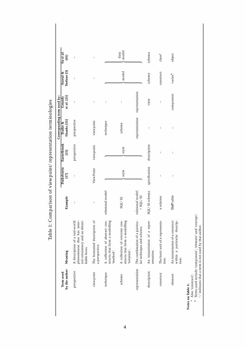
because R is implied by T and S in the description and would therefore be redundant.Some examples of construct and element expressions are given in Table 3. Both types
of expression may specify a list, as illustrated by the last two examples.
Table 3: Examples of construct and element expressions
Re(E -R,ERDMartin) [ENTITYTYPE]denotes the generic entity construct of the E-R/Martin representationR e
D1(V,FuncDep,FDDSmith) [s : SINGLEVALUED ]denotes a single-valued dependency element in the Smith notationfunctional dependency description D1
D2(V,Relational ,SQL/92 ) [c1, . . . , cn : COLUMN]denotes a collection of column elements in the SQL/92 description D2
Rd(DataFlow ,DFDG&S )[DATASTORE,DATAFLOW]denotes the data store and data flow constructs of the data flowmodelling/Gane & Sarson representationRd
6 Conclusion
In this paper has been described a framework for discussing the use of multiple mod-elling representations to describe a viewpoint. Earlier work on the use of multiple repre-sentations has produced a diverse and potentially confusing set of terminologies, noneof which provides a complete set of terms covering all concepts in the area. Viewpointconcepts provide a useful framework within which to discuss the use of multiple repre-sentations, but there is a lack of clarity over the definitions of the terms ‘representation’,‘technique’ and ‘scheme’.
To remedy these issues, the author has clarified the definitions of ‘representation’,‘technique’ and ‘scheme’, and extended the viewpoint framework with the concepts ofdescription, construct of a representation and element of a description. Also describedwas an abstract notation for writing representation, description, construct and elementexpressions.
The framework described in this paper provides a consistent, integrated terminol-ogy and notation for researchers working on the use of multiple representations to de-scribe a viewpoint.
13

References[1] Paolo Atzeni and Riccardo Torlone. Schema translation between heterogeneous data mod-
els in a lattice framework. In Robert Meersman and Leo Mark, editors, Database ApplicationsSemantics, Sixth IFIP TC-2 Working Conference on Data Semantics (DS-6), pages 345–361, StoneMountain, Atlanta, Georgia, USA, May 30–June 2 1995. IFIP, Chapman & Hall, London.
[2] Paolo Atzeni and Riccardo Torlone. Management of multiple models in an extensibledatabase design tool. In P. Apers, M. Bouzeghoub, and G. Gardarin, editors, Fifth Interna-tional Conference on Extending Database Technology (EDBT’96), volume 1057 of Lecture Notesin Computer Science, pages 79–95, Avignon, France, March 25–29 1996. Springer-Verlag.
[3] Paolo Atzeni and Riccardo Torlone. MDM: A multiple-data-model tool for the manage-ment of heterogeneous database schemes. In Joan M. Peckman, editor, SIGMOD 1997 Inter-national Conference on the Management of Data, pages 528–531, Tucson, Arizona, May 13–151997. ACM, ACM Press.
[4] S. M. Brien and J. E. Nicholls. Z base standard. Technical Monograph PRG-107, OxfordUniversity Computing Laboratory, Oxford, UK, nov 1992.
[5] Marc H. Brown. Zeus: A system for algorithm animation and multi-view editing. ResearchReport 75, Digital Equipment Corporation, Systems Research Center, Palo Alto, California,28 February 1992.
[6] R.G.G. Cattell, Douglas K. Barry, Mark Berler, Jeff Eastman, David Jordan, Craig Russell,Olaf Schadow, Torsten Stanienda, and Fernando Velez. The Object Data Standard: ODMG3.0. Morgan Kaufmann, San Francisco, California, 2000.
[7] P.B. Checkland. Systems Thinking, Systems Practice. John Wiley & Sons, Chichester, England,1981.
[8] Peter Pin-Shan Chen. The entity-relationship model — Toward a unified view of data.ACM Transactions on Database Systems, 1(1), 1976.
[9] E.F. Codd. A relational model of data for large shared data banks. Communications of theACM, 13(6), 1970.
[10] Peta Darke and Graeme Shanks. Viewpoint developments for requirements definition: Ananalysis of concepts, issues and approaches. Working Paper 21/94, Department of Infor-mation Systems, Monash University, Melbourne, Australia, December 1994.
[11] Peta Darke and Graeme Shanks. Viewpoint development for requirements definition: To-wards a conceptual framework. In Sixth Australasian Conference on Information Systems(ACIS’95), pages 277–288, Perth, Australia, September 26–29 1995.
[12] Peta Darke and Graeme Shanks. Stakeholder viewpoints in requirements definition: Aframework for understanding viewpoint development approaches. Requirements Engineer-ing, 1:88–105, 1996.
[13] C.J. Date. An Introduction to Database Systems. Addison-Wesley, Reading, Massachusetts,seventh edition, 2000.
[14] C.J. Date and Hugh Darwen. A Guide to the SQL Standard. Addison-Wesley, Reading, Mas-sachusetts, fourth edition, 1997.
[15] Steve M. Easterbrook. Elicitation of Requirements from Multiple Perspectives. PhD thesis,Imperial College of Science Technology and Medicine, University of London, London, 1991.
14

[16] Steve M. Easterbrook and Bashar A. Nuseibeh. Using ViewPoints for inconsistency man-agement. Software Engineering Journal, 11(1):31–43, 1996.
[17] A.C.W. Finkelstein, M. Goedicke, J. Kramer, and C. Niskier. ViewPoint oriented softwaredevelopment: Methods and viewpoints in requirements engineering. In J.A. Bergstra andL.M.G. Feijs, editors, Second Meteor Workshop on Methods for Formal Specification, volume 490of Lecture Notes in Computer Science, pages 29–54, Mierlo, The Netherlands, September 1989.Springer-Verlag.
[18] C. Gane and T. Sarson. Structured Systems Analysis: Tools and Techniques. Prentice-HallSoftware Series. Prentice-Hall, Englewood Cliffs, New Jersey, 1979.
[19] S. Greenspan, J. Mylopoulos, and A. Borgida. On formal requirements modeling languages:RML revisited. In Bruno Fadini, editor, Sixteenth International Conference on Software Engi-neering, pages 135–148, Sorrento, Italy, May 1994. IEEE Computer Society Press.
[20] John C. Grundy. Multiple Textual and Graphical Views for Interactive Software Development En-vironments. PhD thesis, Department of Computer Science, University of Auckland, Auck-land, New Zealand, June 1993.
[21] John C. Grundy and John G. Hosking. Constructing integrated software development envi-ronments with MViews. International Journal of Applied Software Technology, 2(3/4):133–160,1997.
[22] John C. Grundy, John G. Hosking, and Warwick B. Mugridge. Supporting flexible consis-tency management via discrete change description propagation. Software — Practice andExperience, 26(9):1053–1083, September 1996.
[23] John C. Grundy and John R. Venable. Providing integrated support for multiple de-velopment notations. In Seventh Conference on Advanced Information Systems Engineering(CAiSE’95), volume 932 of Lecture Notes in Computer Science, pages 255–268, Finland, June1995. Springer-Verlag.
[24] John G. Hosking, Warwick Mugridge, Robert Amor, and John Grundy. Keeping thingsconsistent. New Zealand Journal of Computing, 6(1):353–362, August 1995.
[25] P. Hsia, J. Samuel, J. Gao, D. Kung, Y. Toyoshima, and C. Chen. Formal approach to scenarioanalysis. IEEE Software, 11(2):33–41, March 1994.
[26] Richard Hull and Roger King. Semantic database modeling: Survey, applications, andresearch issues. ACM Computing Surveys, 19(3):201–260, 1987.
[27] D.A. Jacobs and C.D. Marlin. Software process representation to support multiple views.International Journal of Software Engineering and Knowledge Engineering, 5(4), December 1995.
[28] Gerald Kotonya and Ian Sommerville. Requirements engineering with viewpoints. SoftwareEngineering Journal, 11(1):5–18, 1996.
[29] James Martin. Information Engineering, Book II: Planning and Analysis. Prentice-Hall, Engle-wood Cliffs, New Jersey, revised edition, 1990.
[30] S. Meyers. Difficulties in integrating multiview environments. IEEE Software, 8(1):49–57,January 1991.
[31] Pierre-Alain Muller. Instant UML. Wrox Press, Birmingham, 1997.
15

[32] G. Mullery. CORE — A method for controlled requirements specification. In Fourth Interna-tional Conference on Software Engineering, pages 126–135, Munich, Germany, September 17–19 1979. IEEE Computer Society Press.
[33] B. Nuseibeh, J. Kramer, and A.C.W. Finkelstein. A framework for expressing the relation-ships between multiple views in requirements specification. IEEE Transactions on SoftwareEngineering, 20(10):760–773, 1994.
[34] Richard T. Pascoe and John P. Penny. Constructing interfaces between (and within) ge-ographical information systems. International Journal of Geographical Information Systems,9(3):275–291, 1995.
[35] Steven P. Reiss. Connecting tools using message passing in the Field environment. IEEESoftware, 7(7):57–66, July 1990.
[36] Henry C. Smith. Database design: Composing fully normalized tables from a rigorousdependency diagram. Communications of the ACM, 28(8):826–838, 1985.
[37] Nigel Stanger. Modifications to Smith’s method for deriving normalised relations froma functional dependency diagram. Discussion paper 99/23, Department of InformationScience, University of Otago, Dunedin, New Zealand, December 1999.
[38] Nigel Stanger. Using Multiple Representations Within a Viewpoint. PhD thesis, Department ofInformation Science, University of Otago, Dunedin, New Zealand, December 1999.
[39] Nigel Stanger and Richard Pascoe. Environments for viewpoint representations. In RobertGalliers, Sven Carlsson, Claudia Loebbecke, Ciaran Murphy, Hans Hansen, and RamonO’Callaghan, editors, Fifth European Conference on Information Systems (ECIS’97), volume I,pages 367–382, Cork, Ireland, June 19–21 1997. Cork Publishing.
[40] S.Y.W. Su and S.C. Fang. A neutral semantic representation for data model and schematranslation. Technical report TR-93-023, University of Florida, Gainesville, Florida, July1993.
[41] S.Y.W. Su, S.C. Fang, and H. Lam. An object-oriented rule-based approach to data modeland schema translation. Technical report TR-92-015, University of Florida, Gainesville,Florida, 1992.
[42] D. Tsichritzis and F. Lochovsky. Data Models. Prentice-Hall, 1982.
16


![1 Lesson 1. 2 Topic Outline Introduction Objectives Assumptions Framework (A Jesus-centered Viewpoint ) Resurrected [1] Application to Us](https://img.pdfslide.net/doc/110x75/56649d385503460f94a11615/1-lesson-1-2-topic-outline-introduction-objectives-assumptions.jpg)