Embed Size (px)
Citation preview
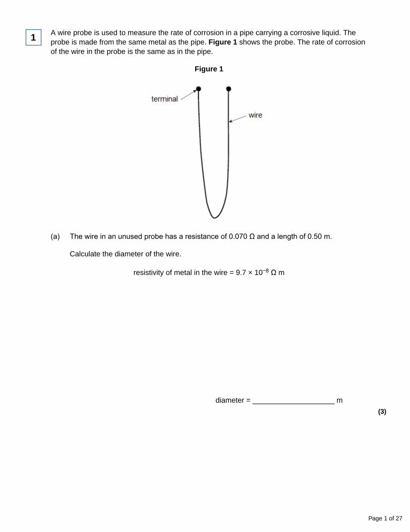
A wire probe is used to measure the rate of corrosion in a pipe carrying a corrosive liquid. Theprobe is made from the same metal as the pipe. Figure 1 shows the probe. The rate of corrosionof the wire in the probe is the same as in the pipe.
Figure 1
(a) The wire in an unused probe has a resistance of 0.070 Ω and a length of 0.50 m.
Calculate the diameter of the wire.
resistivity of metal in the wire = 9.7 × 10⁻⁸ Ω m
diameter = ____________________ m
(3)
1
Page 1 of 27
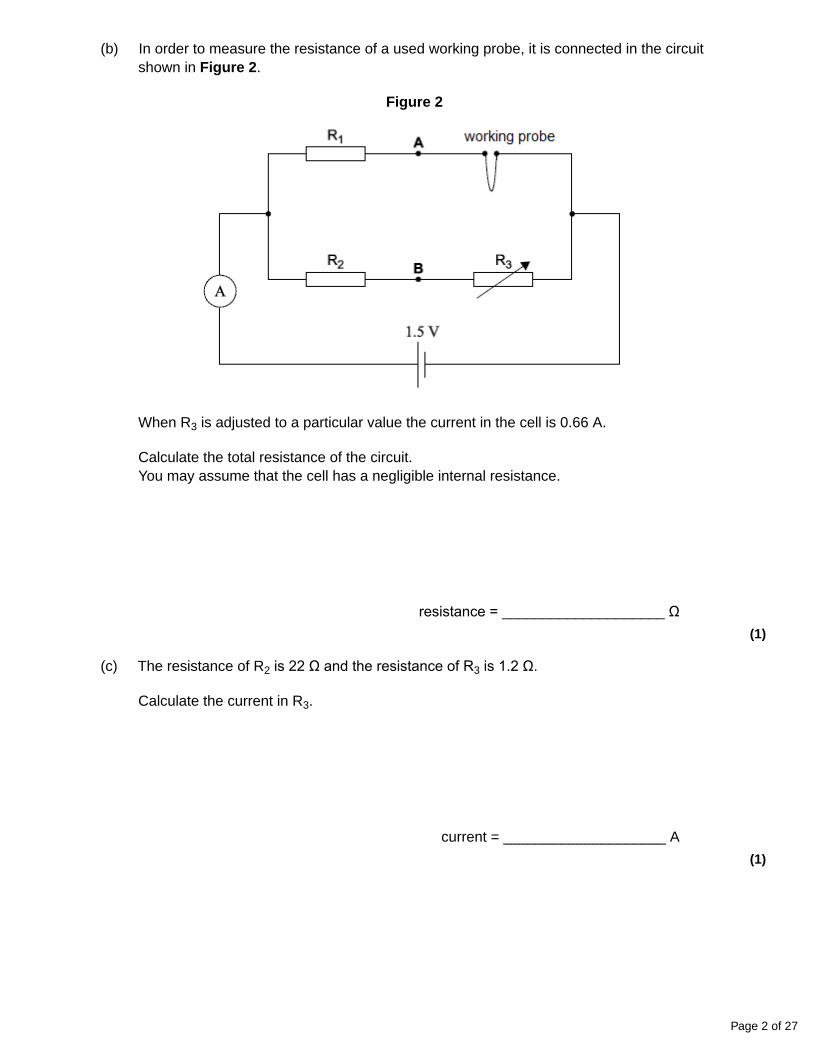
(b) In order to measure the resistance of a used working probe, it is connected in the circuitshown in Figure 2.
Figure 2
When R3 is adjusted to a particular value the current in the cell is 0.66 A.
Calculate the total resistance of the circuit.You may assume that the cell has a negligible internal resistance.
resistance = ____________________ Ω(1)
(c) The resistance of R2 is 22 Ω and the resistance of R3 is 1.2 Ω.
Calculate the current in R3.
current = ____________________ A
(1)
Page 2 of 27
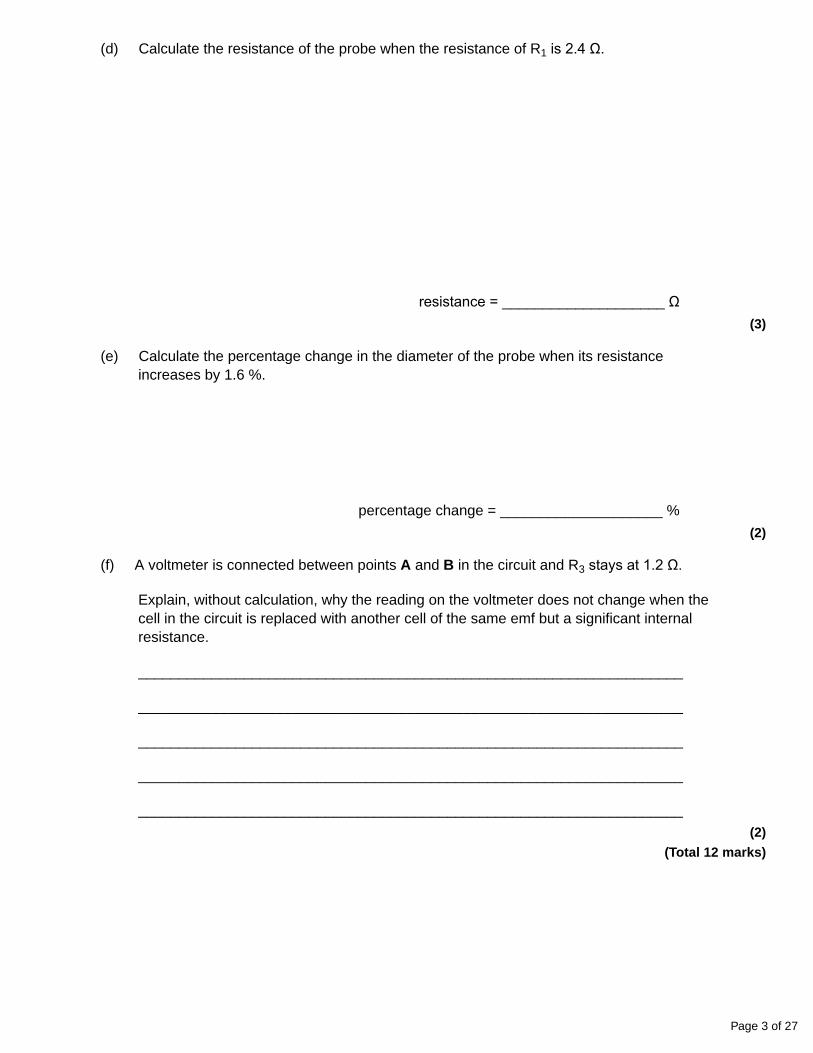
(d) Calculate the resistance of the probe when the resistance of R1 is 2.4 Ω.
resistance = ____________________ Ω(3)
(e) Calculate the percentage change in the diameter of the probe when its resistanceincreases by 1.6 %.
percentage change = ____________________ %
(2)
(f) A voltmeter is connected between points A and B in the circuit and R3 stays at 1.2 Ω.
Explain, without calculation, why the reading on the voltmeter does not change when thecell in the circuit is replaced with another cell of the same emf but a significant internalresistance.
___________________________________________________________________
___________________________________________________________________
___________________________________________________________________
___________________________________________________________________
___________________________________________________________________
(2)
(Total 12 marks)
Page 3 of 27
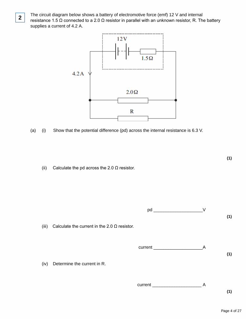
The circuit diagram below shows a battery of electromotive force (emf) 12 V and internalresistance 1.5 Ω connected to a 2.0 Ω resistor in parallel with an unknown resistor, R. The batterysupplies a current of 4.2 A.
(a) (i) Show that the potential difference (pd) across the internal resistance is 6.3 V.
(1)
2
(ii) Calculate the pd across the 2.0 Ω resistor.
pd ____________________V
(1)
(iii) Calculate the current in the 2.0 Ω resistor.
current ____________________A
(1)
(iv) Determine the current in R.
current ____________________ A
(1)
Page 4 of 27
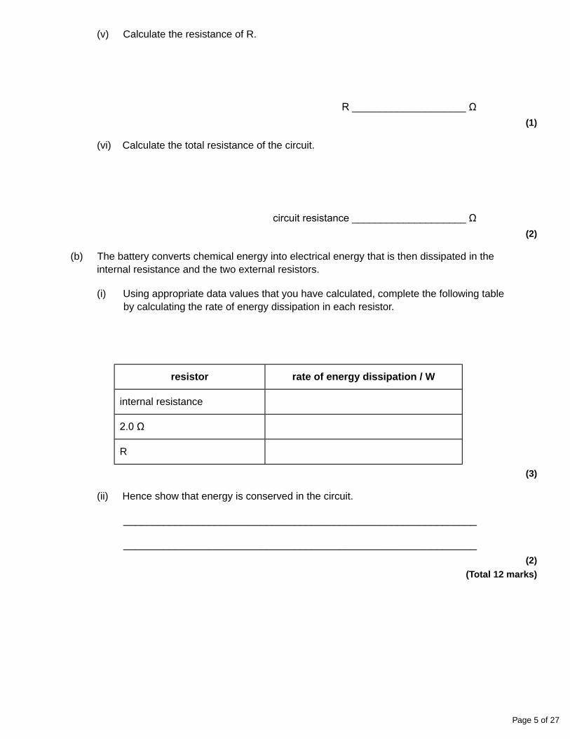
(v) Calculate the resistance of R.
R ____________________ Ω(1)
(vi) Calculate the total resistance of the circuit.
circuit resistance ____________________ Ω(2)
(b) The battery converts chemical energy into electrical energy that is then dissipated in theinternal resistance and the two external resistors.
(i) Using appropriate data values that you have calculated, complete the following tableby calculating the rate of energy dissipation in each resistor.
resistor rate of energy dissipation / W
internal resistance
2.0 Ω
R
(3)
(ii) Hence show that energy is conserved in the circuit.
______________________________________________________________
______________________________________________________________
(2)
(Total 12 marks)
Page 5 of 27
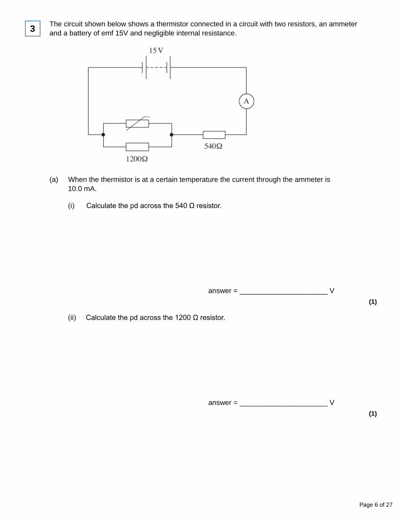
The circuit shown below shows a thermistor connected in a circuit with two resistors, an ammeterand a battery of emf 15V and negligible internal resistance.
(a) When the thermistor is at a certain temperature the current through the ammeter is10.0 mA.
(i) Calculate the pd across the 540 Ω resistor.
answer = ______________________ V
(1)
3
(ii) Calculate the pd across the 1200 Ω resistor.
answer = ______________________ V
(1)
Page 6 of 27
(iii) Calculate the resistance of the parallel combination of the resistor and the thermistor.
answer = ______________________ Ω(2)
(iv) Calculate the resistance of the thermistor.
answer = ______________________ Ω(2)
(b) The temperature of the thermistor is increased so that its resistance decreases.State and explain what happens to the pd across the 1200 Ω resistor.
___________________________________________________________________
___________________________________________________________________
___________________________________________________________________
___________________________________________________________________
(3)
(Total 9 marks)
State what is meant by a superconductor.
_______________________________________________________________________
_______________________________________________________________________
(Total 1 mark)
4
Page 7 of 27
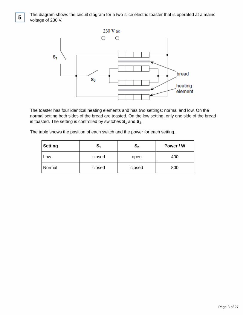
The diagram shows the circuit diagram for a two-slice electric toaster that is operated at a mainsvoltage of 230 V.
5
The toaster has four identical heating elements and has two settings: normal and low. On thenormal setting both sides of the bread are toasted. On the low setting, only one side of the breadis toasted. The setting is controlled by switches S1 and S2.
The table shows the position of each switch and the power for each setting.
Setting S1 S2 Power / W
Low closed open 400
Normal closed closed 800
Page 8 of 27
(a) Calculate the current in S2 when the normal setting is selected.
current ____________________ A
(2)
(b) (i) Show that the resistance of one heating element is approximately 260 Ω when thetoaster is operating at its working temperature.
(2)
(ii) Calculate the total resistance when the normal setting is selected.
resistance ____________________ Ω(2)
(iii) Each heating element is made of nichrome wire of diameter 0.15 mm.The nichrome wire is wrapped around an insulating board.
Determine the length of nichrome wire needed to provide a resistance of 260 Ω.
resistivity of nichrome at the working temperature = 1.1 × 10⁻⁶ Ω m
length of wire ____________________ m
(3)
(c) Explain why the resistivity of the nichrome wire changes with temperature.
___________________________________________________________________
___________________________________________________________________
___________________________________________________________________
___________________________________________________________________
___________________________________________________________________
(3)
Page 9 of 27
(d) The nichrome wire has an equilibrium temperature of 174°C when the toaster is operating.
Calculate the peak wavelength of the electromagnetic radiation emitted by the wire.
Give your answer to an appropriate number of significant figures.
peak wavelength ____________________ m
(3)
(Total 15 marks)
A cordless phone handset contains two rechargeable cells connected in series. Each cell has anemf of 2.0 V and, when fully charged, the combination stores energy sufficient to provide 850 mAfor 1 hour.
(a) Calculate the total energy stored by the two cells when fully charged.
energy stored ____________________ J
(3)
6
(b) The internal resistance of each cell is 0.60 Ω.Calculate the potential difference across the two cells when they are connected in seriesacross a 20.0 Ω load.
potential difference ____________________ V
(3)
(Total 6 marks)
Page 10 of 27
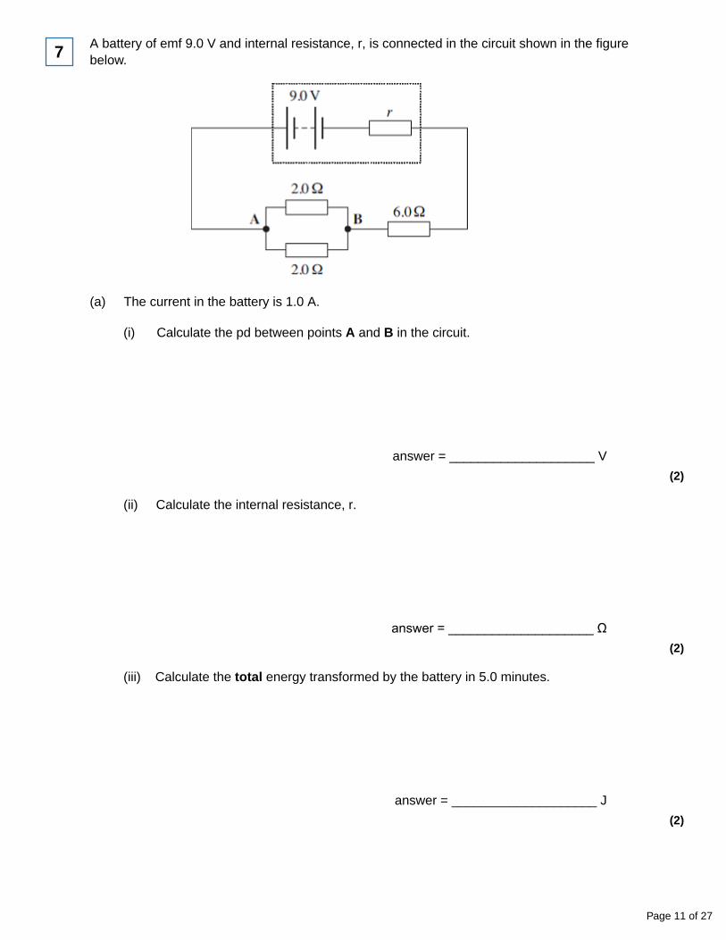
A battery of emf 9.0 V and internal resistance, r, is connected in the circuit shown in the figurebelow.
(a) The current in the battery is 1.0 A.
(i) Calculate the pd between points A and B in the circuit.
answer = ____________________ V
(2)
7
(ii) Calculate the internal resistance, r.
answer = ____________________ Ω(2)
(iii) Calculate the total energy transformed by the battery in 5.0 minutes.
answer = ____________________ J
(2)
Page 11 of 27
(iv) Calculate the percentage of the energy calculated in part (iii) that is dissipated in thebattery in 5.0 minutes.
answer = ____________________ %
(2)
(b) State and explain one reason why it is an advantage for a rechargeable battery to have alow internal resistance.
___________________________________________________________________
___________________________________________________________________
___________________________________________________________________
___________________________________________________________________
(2)
(Total 10 marks)
A car battery has an emf of 12 V and an internal resistance of 9.5 × 10⁻³ Ω. When the battery isused to start a car the current through the battery is 420 A.
(a) Calculate the voltage across the terminals of the battery, when the current through thebattery is 420 A.
___________________________________________________________________
___________________________________________________________________
___________________________________________________________________
___________________________________________________________________
answer ____________________ V
(2)
8
Page 12 of 27
(b) The copper cable connecting the starter motor to the battery has a length of 0.75 m andcross-sectional area of 7.9 × 10⁻⁵ m2. The resistance of the cable is 1.6 × 10⁻³ Ω.
Calculate the resistivity of the copper giving an appropriate unit.
___________________________________________________________________
___________________________________________________________________
___________________________________________________________________
___________________________________________________________________
___________________________________________________________________
___________________________________________________________________
answer ____________________
(3)
(Total 5 marks)
Page 13 of 27
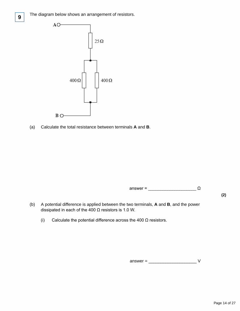
The diagram below shows an arrangement of resistors.
(a) Calculate the total resistance between terminals A and B.
answer = ____________________ Ω(2)
9
(b) A potential difference is applied between the two terminals, A and B, and the powerdissipated in each of the 400 Ω resistors is 1.0 W.
(i) Calculate the potential difference across the 400 Ω resistors.
answer = ____________________ V
Page 14 of 27
(ii) Calculate the current through the 25 Ω resistor.
answer = ____________________ A
(iii) Calculate the potential difference applied to terminals A and B.
answer = ____________________ V
(6)
(Total 8 marks)
When transmitting electricity, energy is lost owing to the resistance of the cables.
Calculate the resistance of 200 km of copper cable with cross-sectional area 1.5 × 10⁻⁵ m2.
resistivity of copper = 1.7 × 10⁻⁸ Ω m
resistance ____________________
(Total 3 marks)
10
The units of physical quantities can be expressed in terms of the fundamental (base) units of theSI system. In which line in the table are the fundamental units correctly matched to the physicalquantity?
Physical quantity Fundamental units
A charge A s−1
B power kg m2 s−3
C potential difference kg m2 s A−1
D energy kg m2 s−1
(Total 1 mark)
11
Page 15 of 27
When the temperature of a copper wire increases, its ability to conduct electricity
A remains the same.
B increases.
C decreases.
D remains the same at first and then increases.
(Total 1 mark)
12
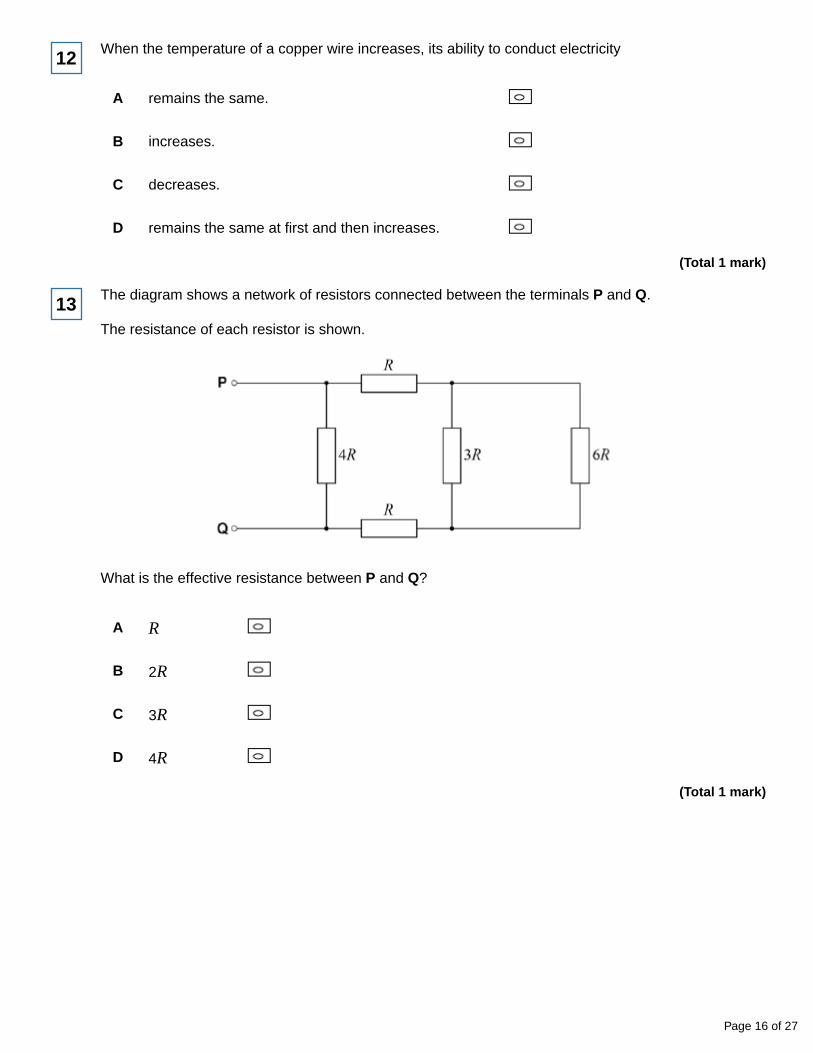
The diagram shows a network of resistors connected between the terminals P and Q.
The resistance of each resistor is shown.
13
What is the effective resistance between P and Q?
A R
B 2R
C 3R
D 4R
(Total 1 mark)
Page 16 of 27
A metal wire has a length l and a cross-sectional area A. When a potential difference V is
applied to the wire, there is a current I in the wire.
What is the resistivity of the wire?
A
B
C
D
(Total 1 mark)
14
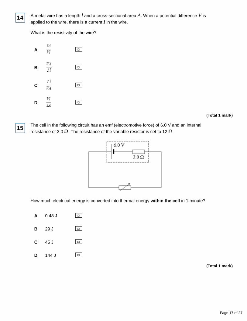
The cell in the following circuit has an emf (electromotive force) of 6.0 V and an internal
resistance of 3.0 Ω. The resistance of the variable resistor is set to 12 Ω.
15
How much electrical energy is converted into thermal energy within the cell in 1 minute?
A 0.48 J
B 29 J
C 45 J
D 144 J
(Total 1 mark)
Page 17 of 27
Three identical cells, each of internal resistance R, are connected in series with an externalresistor of resistance R. The current in the external resistor is I. If one of the cells is reversed inthe circuit, what is the new current in the external resistor?
A
B
C
D
(Total 1 mark)
16
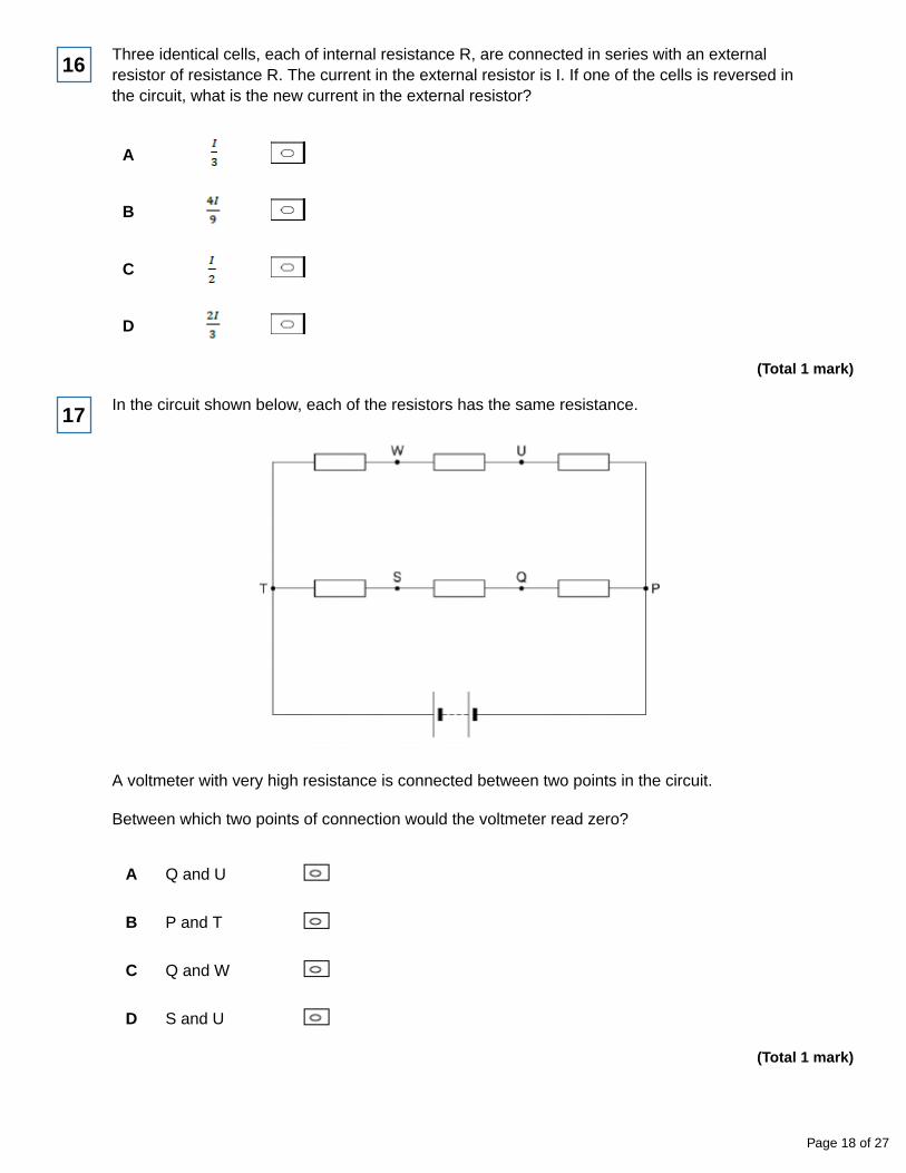
In the circuit shown below, each of the resistors has the same resistance.
17
A voltmeter with very high resistance is connected between two points in the circuit.
Between which two points of connection would the voltmeter read zero?
A Q and U
B P and T
C Q and W
D S and U
(Total 1 mark)
Page 18 of 27
Mark schemes
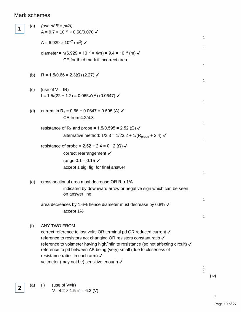
(a) (use of R = ρl/A)A = 9.7 × 10−8 × 0.50/0.070
1
A = 6.929 × 10⁻⁷ (m2) 1
diameter = √(6.929 × 10−7 × 4/π) = 9.4 × 10⁻⁴ (m) CE for third mark if incorrect area
1
1
(b) R = 1.5/0.66 = 2.3(Ω) (2.27) 1
(c) (use of V = IR)I = 1.5/(22 + 1.2) = 0.065(A) (0.0647)
1
(d) current in R1 = 0.66 − 0.0647 = 0.595 (A) CE from 4.2/4.3
1
resistance of R1 and probe = 1.5/0.595 = 2.52 (Ω)
alternative method: 1/2.3 = 1/23.2 + 1/(Rprobe + 2.4) 1
resistance of probe = 2.52 − 2.4 = 0.12 (Ω) correct rearrangement range 0.1 – 0.15 accept 1 sig. fig. for final answer
1
(e) cross-sectional area must decrease OR R α 1/Aindicated by downward arrow or negative sign which can be seenon answer line
1
area decreases by 1.6% hence diameter must decrease by 0.8% accept 1%
1
(f) ANY TWO FROMcorrect reference to lost volts OR terminal pd OR reduced current reference to resistors not changing OR resistors constant ratio reference to voltmeter having high/infinite resistance (so not affecting circuit) reference to pd between AB being (very) small (due to closeness ofresistance ratios in each arm) voltmeter (may not be) sensitive enough
11
[12]
(a) (i) (use of V=Ir)V= 4.2 × 1.5 = 6.3 (V)
1
2
Page 19 of 27
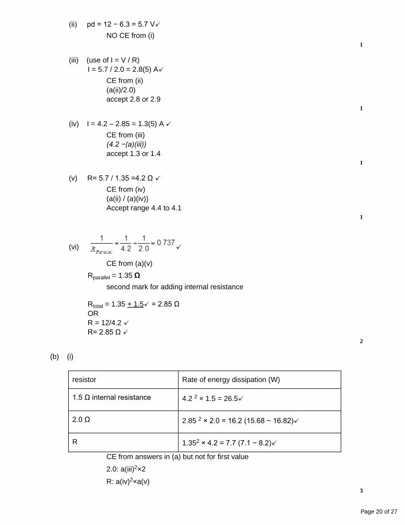
(ii) pd = 12 − 6.3 = 5.7 V
NO CE from (i)1
(iii) (use of I = V / R)I = 5.7 / 2.0 = 2.8(5) A
CE from (ii)(a(ii)/2.0)accept 2.8 or 2.9
1
(iv) I = 4.2 – 2.85 = 1.3(5) A
CE from (iii)(4.2 −(a)(iii))accept 1.3 or 1.4
1
(v) R= 5.7 / 1.35 =4.2 Ω
CE from (iv)(a(ii) / (a)(iv))Accept range 4.4 to 4.1
1
(vi)
Rparallel = 1.35 Ωsecond mark for adding internal resistance
Rtotal = 1.35 + 1.5 = 2.85 ΩORR = 12/4.2 R= 2.85 Ω
2
CE from (a)(v)
resistor Rate of energy dissipation (W)
1.5 Ω internal resistance 4.2 2 × 1.5 = 26.5
2.0 Ω 2.85 2 × 2.0 = 16.2 (15.68 − 16.82)
R 1.352 × 4.2 = 7.7 (7.1 − 8.2)
(b) (i)
CE from answers in (a) but not for first value
2.0: a(iii)2×2
R: a(iv)2×a(v)3
Page 20 of 27
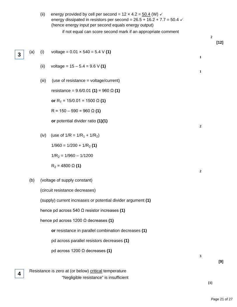
(ii) energy provided by cell per second = 12 × 4.2 = 50.4 (W) energy dissipated in resistors per second = 26.5 + 16.2 + 7.7 = 50.4 (hence energy input per second equals energy output)
if not equal can score second mark if an appropriate comment2
[12]
(a) (i) voltage = 0.01 × 540 = 5.4 V (1)1
(ii) voltage = 15 – 5.4 = 9.6 V (1)1
3
(iii) (use of resistance = voltage/current)
resistance = 9.6/0.01 (1) = 960 Ω (1)
or RT = 15/0.01 = 1500 Ω (1)
R = 150 – 590 = 960 Ω (1)
or potential divider ratio (1)(1)2
(iv) (use of 1/R = 1/R1 + 1/R2)
1/960 = 1/200 + 1/R2 (1)
1/R2 = 1/960 – 1/1200
R2 = 4800 Ω (1)2
(b) (voltage of supply constant)
(circuit resistance decreases)
(supply) current increases or potential divider argument (1)
hence pd across 540 Ω resistor increases (1)
hence pd across 1200 Ω decreases (1)
or resistance in parallel combination decreases (1)
pd across parallel resistors decreases (1)
pd across 1200 Ω decreases (1)3
[9]
Resistance is zero at (or below) critical temperature
“Negligible resistance” is insufficient[1]
4
Page 21 of 27
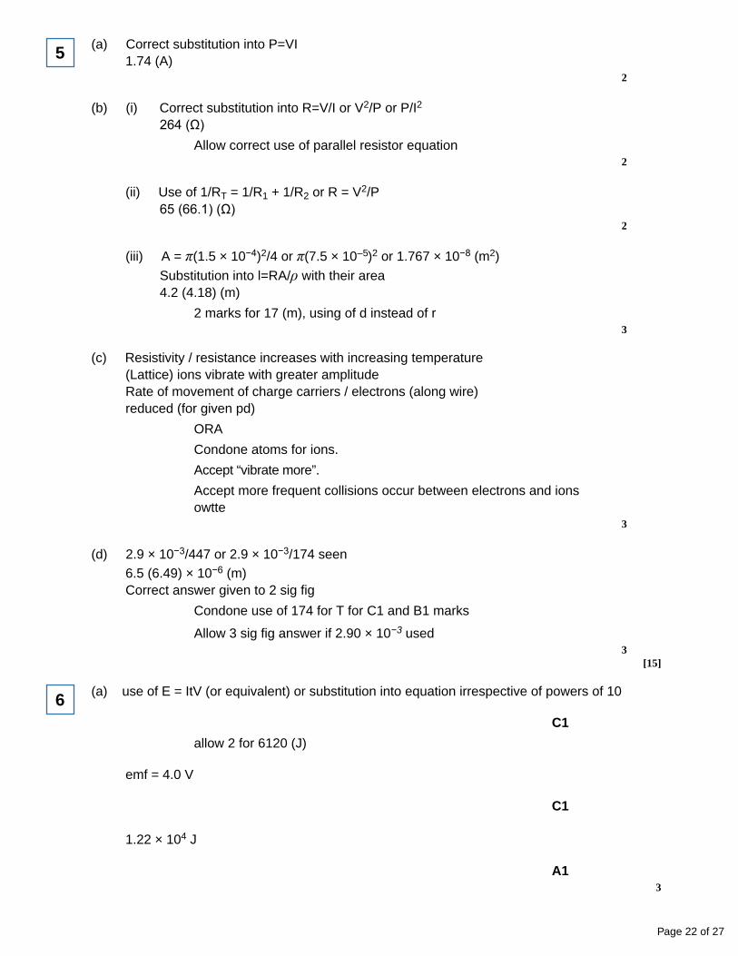
(a) Correct substitution into P=VI1.74 (A)
2
5
(b) (i) Correct substitution into R=V/I or V2/P or P/I2
264 (Ω)Allow correct use of parallel resistor equation
2
(ii) Use of 1/RT = 1/R1 + 1/R2 or R = V2/P65 (66.1) (Ω)
2
(iii) A = π(1.5 × 10⁻⁴)2/4 or π(7.5 × 10⁻⁵)2 or 1.767 × 10⁻⁸ (m2)
Substitution into l=RA/ρ with their area4.2 (4.18) (m)
2 marks for 17 (m), using of d instead of r3
(c) Resistivity / resistance increases with increasing temperature(Lattice) ions vibrate with greater amplitudeRate of movement of charge carriers / electrons (along wire)reduced (for given pd)
ORA
Condone atoms for ions.
Accept “vibrate more”.
Accept more frequent collisions occur between electrons and ionsowtte
3
(d) 2.9 × 10⁻³/447 or 2.9 × 10⁻³/174 seen6.5 (6.49) × 10−6 (m)Correct answer given to 2 sig fig
Condone use of 174 for T for C1 and B1 marks
Allow 3 sig fig answer if 2.90 × 10⁻³ used3
[15]
(a) use of E = ItV (or equivalent) or substitution into equation irrespective of powers of 10
C1
allow 2 for 6120 (J)
emf = 4.0 V
C1
1.22 × 10⁴ J
A13
6
Page 22 of 27
(b) Internal resistance = 1.2 (Ω)
C1
allow 2 for 0.22(6) V
Current calculated (0.19 A) or potential divider formula used 3.7(7) V
C1
A13
[6]
(a) (i) (use of V = IR)
Rtotal = 1 (ohm)
V = 1 × 1 = 1.0 V 2
7
(ii) (use of V = IR)
R = 9.0/1.0 = 9.0 Ω
r = 9.0 − 1.0 − 6.0 = 2.0 Ω
or use of (E = I(R + r))
9.0 = 1(7 + r)
r = 9.0 − 7.0 = 2.0 Ω 2
(iii) (use of W = Vlt)
W = 9.0 × 1.0 × 5 × 60
W = 2700 J 2
(iv) energy dissipated in internal resistance = 12 × 2.0 × 5 × 60 = 600 (J)
percentage = 100 × 600/2700 = 22% CE from part aii2
Page 23 of 27
(b) internal resistance limits current
hence can provide higher current
or energy wasted in internal resistance/battery
less energy wasted (with lower internal resistance)
or charges quicker
as current higher or less energy wasted
or (lower internal resistance) means higher terminal pd/voltage
as less pd across internal resistance or mention of lost volts 2
[10]
(a) (use of E = V + Ir)
12 = V + 420 × 0.0095 (1)
V = 8.0(1)V (1)2
8
(b) ρ = RA/I = 1.6 × 10–3 × 7.9 × 10–5/0.75 (1)
R = 1.7 × 10⁻⁷ (1) Ωm (1)3
[5]
(a) (use of 1/Rtotal = 1/R1 + 1/R2)
1/Rtotal = 1/400 + 1/400 = 2/400
Rtotal = 200 Ω (1) (working does not need to be shown)
hence total resistance = 25 + 200 = 225Ω (1)2
9
(b) (i) (use of P = V2/R)
1 = V2/400 (1)
V2 = 400 (working does not need to be shown)
V = 20V (1)
(ii) (use of I = V/R)
I = 20/400 = 0.05A (1) (working does not need to be shown)
hence current = 2 × 0.05 = 0.10A (1)
Page 24 of 27
(iii) (use of V = IR)
pd across 25Ω resistor = 25 × 0.10 = 2.5V (1)(working does not need to be shown)
hence maximum applied pd = 20 + 2.5 = 22.5V (1)6
[8]
use of R = (1)
227 (1)
Ω (1)
[3]
10
B
[1]11
C
[1]12
B
[1]13
B
[1]14
B
[1]15
A
[1]16
A
[1]17
Page 25 of 27
Examiner reports
Experience from past physics exams at this level indicates that students are better at answeringquantitative questions involving electric circuits and this is supported by evidence from thisquestion where the calculations were frequently done well. Part (a) required students to calculatethe diameter of the wire and a high proportion of students were able to do this successfully. Fullmarks were obtained by over 70% of students. There was more variation in parts (b), (c) and (d).While the majority of students were able to calculate the resistance of the circuit, analysing theparallel arrangement was more discriminating. In particular, calculating the resistance of theprobe proved challenging. A common mistake was the assumption that the current dividedequally in the two branches and therefore the current in the probe was the same as thatcalculated for R3. Many students found (e) difficult and tried to determine the percentage changein diameter using extended calculations which frequently led to arithmetic errors. The first markwas for recognition that the diameter must decreases and any indication of this such as adownward arrow or negative sign was accepted. The marks obtained for part (f) weredisappointing in spite of the mark scheme being expanded to accept a greater range of answers.Very few students picked up that the question referred to the voltmeter reading rather than the pdbetween A and B. The first marking point was for explaining the effect the internal resistancewould have on the circuit by for example reducing the current or terminal pd. The second markwas for a sensible suggestion explaining why the voltmeter reading did not change such asrealizing that the closeness of the resistance ratios would make the pd being measured verysmall. Having the bridge circuit slightly off balance did mean that a comment on the highresistance of the voltmeter was relevant and some did identify this point.
1
Part (a) was highly structured and led candidates through a full circuit calculation in stages. Thisapproach appeared to have helped them and more successful solutions were seen than hasbeen the case in the past with this type of circuit.
The part that caused the most problems was (a) (ii) with a significant proportion of candidates notappreciating that the pd across the 2.0 Ω resistor was the same as that across resistor R.Candidates were however, not penalized when they carried their incorrect answer to subsequentparts and consequently the remaining calculations were often carried out successfully.
Part (b) proved to be much more demanding and only about half the candidates managed tocomplete the table for the rate of energy dissipation successfully.
The demonstration of energy conservation in part (b) (ii) provided an even greater challenge andonly about a third of candidates provided a convincing analysis of energy conservation in thecircuit. A fifth of candidates made no attempt at this part of the question.
2
This question proved to be very discriminating with only the more able candidates able to scorehigh marks. The calculations involved in part (a) proved too challenging for many candidates.Part (a) (i) and (ii) generated the most correct responses, but the remainder of the analysis wasonly accessible to the more able candidates.
Part (b) required analysis without calculation and the majority of explanations seen wereconfused and not self consistent. Many candidates stated that more current goes through thethermistor and therefore the pd across it falls, resulting in the pd across the parallel 1200 Ωresistor increasing. Another common misunderstanding was the effect that the decreasingthermistor resistance had on the current through the battery. Many thought that the currentremained constant and, although this still led them to deduce that the pd fell, their argumentsfrequently contained contradictions.
3
Page 26 of 27
Students needed to use the term “critical temperature” in their definition.4(a) Most students obtained the total current but failed to appreciate the need to halve this
value.
(b) A variety of routes were possible for part (i) but clear evidence of the method was expectedto be seen. The ‘parallel resistor’ equation was often invoked but rarely written explicitly.Parts (ii) and (iii) were answered well.
(c) This was poorly answered. Explanations often lacked the required precision. Manystudents clearly thought that nichrome is a semi-conductor.
(d) Most students recognised the need to use Wien’s Law and to convert the temperature tokelvin.
5
It was common for candidates to use an emf of 2.0 V in (a) but most correctly used therelationship of energy = emf × current × time. A minority of candidates used a time of 60 s ratherthan the correct 3600 s and a few misinterpreted 850 mA.
In (b) it was common for candidates to use the 850 mA given in (a) as the current; few calculatedthe correct current (or to correctly use the potential divider formula) and of those that did abouthalf went on to find the ‘lost volts’ rather than the terminal pd.
6
Students fared better in the circuit analysis involved in this question than they did in question 6.Parts (a) (i), (ii) and (iii) were answered well with a significant proportion of students able tocorrectly find the total circuit resistance. The calculation of the parallel network was donecorrectly by the majority of students, although the working shown by many was sometimes notset out properly with the reciprocal of total resistance being equated to the total resistance. Thiswas in part due to the combined resistance being equal to 1 Ω.
Part (a) (iv), in which students had to calculate the energy transformed by the battery in5.0minutes, was not answered as well. A significant proportion of students did not appreciate thatthis was found by multiplying the emf of the battery by the appropriate time. Part (a) (v) causedstudents even more problems and only a minority of the more able students were able tocorrectly calculate the energy dissipated in the internal resistance of the battery.
The final part of this question was well answered with most students giving sensible suggestions.However, one out of two marks was quite common due to students mixing up an explanation witha reason; an example being ‘has a higher terminal pd’ and ‘provides large current’.
7
Part (a) caused similar problems to the question on emf and internal resistance in the Januaryexamination. A common, incorrect approach was to calculate the potential difference across theinternal resistance and quote this as the value of terminal pd.
Part (b) proved to be much more accessible and the calculation only caused a few candidatesproblems. The unit for resistivity does confuse a significant proportion of candidates and this isoften quoted as Ω m–1 or Ω/m.
8
Part (a) was answered well, with many candidates obtaining full marks.
Part (b) caused more problems and the use of the power formula that involves potentialdifference and resistance was quite rare. In part (b) (ii) there was some confusion over potentialdifference and candidates frequently used their answer from part (b) (i). Part (b) (iii) wasanswered much better, with candidates frequently benefiting from consequential error.
9
Page 27 of 27