Embed Size (px)
Citation preview
MS1000Corrosion Meter
Owner’s Manual
Metal SamplesA Division of Alabama Specialty Products, Inc.
152 Metal Samples Rd., Munford, AL 36268Phone: (256) 358-4202 Fax: (256) 358-4515
E-mail: [email protected] Internet: www.metalsamples.com

Table of Contents
I. Introduction ..................................................................... 1A. Background ................................................................... 1B. Instrument Capabilities ................................................... 2C. Applications for the MS1000 ......................................... 6
II. MS1000 Specifications and Features .............................. 7
III. MS1000 Operation ........................................................... 9A. Test Readings ................................................................ 9B. Data Acquisition ............................................................. 9
1. Instantaneous Corrosion Rate Measurements ............ 92. ZRA and EPR Measurements ................................. 10
C. Electrode Installation, Replacement and Care ............... 10D. Correcting for Low Solution Conductivity Effects .......... 11
IV. UNS Constant Table ....................................................... 14
V. Maintenance ................................................................... 16
VI. Troubleshooting .............................................................. 16
VII. Replacement Parts ......................................................... 18
VIII. Warranty ........................................................................ 20
IX. References ...................................................................... 21
MS1000 manual - rev. 15.12

I. Introduction
A. Background
The MS1000 is a portable, hand-held, battery-powered corrosionmeter. This versatile instrument measures the instantaneous corrosionrate with the Linear Polarization Resistance (LPR) technique. It alsomeasures the current flowing between electrodes in the short-circuitedcondition with a high precision zero resistance ammeter (ZRA). TheMS1000 can analyze two-electrode linear polarization resistance orgalvanic type probes.
The principle use of this instrument is to measure corrosion rates undervarious conditions in the plant, field, or lab. In addition to using thisinstrument to monitor corrosion rates, corrosion engineers can also usethe MS1000 to monitor inhibitor effectiveness, identity process upsets,identify localized corrosion events, and evaluate corrective actions inreal time. These measurements are very important since a change in theprocess conditions can lead to dramatic changes in the observedcorrosion rate.
1
B. Instrument Capabilities
Instantaneous Corrosion Rate MeasurementsInstantaneous corrosion rate measurements are made with the linearpolarization resistance (LPR) technique. This technique is a reliableelectrochemical procedure based on principles outlined in ASTM G59Standard Practice for Conducting Potentiodynamic Polarization Resis-tance Measurements.1 An excellent technical review of this technique isgiven elsewhere by Mansfeld.2,3
The determination of a corrosion rate from the parameters measuredwith corrosion probes depends on Faraday’s law. The mass loss,current, potential, and changes in these variables are converted into acorrosion rate. ASTM G102 Standard Practice for Calculation ofCorrosion Rates and Related Information from Electrochemical Mea-surements provides all necessary information for the direct calculation ofthe corrosion rate.4
The method used by the MS1000 for calculating the corrosion rate is asfollows. A low amplitude dc voltage is applied across the electrodesand then the resulting current, normalized to current density, is mea-sured. The voltage is held constant for thirty seconds before measuringthe current so that any capacitance in the oxide layer will be fullycharged. The polarity of the applied voltage is then changed and themeasurement cycle is repeated. Polarity is reversed to minimize poten-tial errors due to possible electrode dissimilarities or changes in theopen circuit potential of the electrodes during the measurement.
The polarization resistance, Rp, of the corroding electrodes is calcu-lated from the slope of the potential-current density plot. Rp is definedas:
Rp = E
i
2
where E is the polarization from the open circuit potential of theelectrodes and i is the measured current density at E. Stern andGeary showed that there is a linear relationship between potential andapplied current at potentials only slightly removed from the corrosionpotential.1 Based on the kinetics of electrochemical reactions andconcepts of mixed potential theory, as discussed by Wagner and Traud,an equation was derived which related the polarization resistance to thecorrosion current density, i
corr.6 The corrosion current density is calcu-
lated as:
where ßa and ß
c are the anodic and cathodic Tafel constants (ie., the
slopes of the anodic and cathodic polarization curves in the Tafelregion).
The instantaneous corrosion rate in mils per year (mpy) is determinedfrom i
corr with the following equation:
icorr =
2.303Rp(ß
a + ß
c)
ßa ß
c
where EW is the equivalent weight, K is a constant for units conversion,and is the density. The equivalent weight depends upon the composi-tion of the alloy. Guidelines for determining the equivalent weight aregiven in ASTM G102.4
Note that this instrument has been designed to calculate the corrosionrate of carbon steel and common grades of stainless steel in mils peryear. In other words, the programmed values of the Tafel slopes,equivalent weight, and density are typical for carbon steel and commongrades of stainless steel. Multiplication factors for copper, admiraltybrass, and lead are included on the front panel of the instrument.
COR(mpy) =icorr
• EW • K
3
The instrument is programmed for electrodes with surface areas of fivecm2. Multiplication factors are also included for flush mount electrodeswith surface areas of 0.5 cm2.
Zero Resistance Ammeter (ZRA) and Equivalent Pitting RateA high precision zero resistance ammeter is used for monitoring theshort-circuit current between electrodes. This total current flowingbetween the electrodes in the short-circuited condition is monitored.The current is displayed in microamps. The zero resistance ammeter(ZRA) function may also be used to monitor the galvanic currentbetween electrodes of different alloys or the area effect of galvaniccorrosion.
Generally, if the magnitude of the ZRA reading divided by 2 is less thanthe corrosion rate, then pitting may be occurring but the pits will prob-ably be shallow and wide; however, pitting may be a serious concern ifthe ZRA/2 is greater than the corrosion rate.
Faraday’s law may be used to calculate the mass of material lost as aresult of the localized corrosion as follows:
W =[( ZRA)/n] • t • EW
F
where W is the mass of the corroded metal in grams, ( ZRA)/n is thetime-integrated ZRA divided by n, the number of days of exposure, t isthe time the current is flowing in seconds, EW is the equivalent weightas previously defined, and F is the Faraday constant, 96480 Coulombs/mol. The mass of the corroded material may be used to calculate a
4
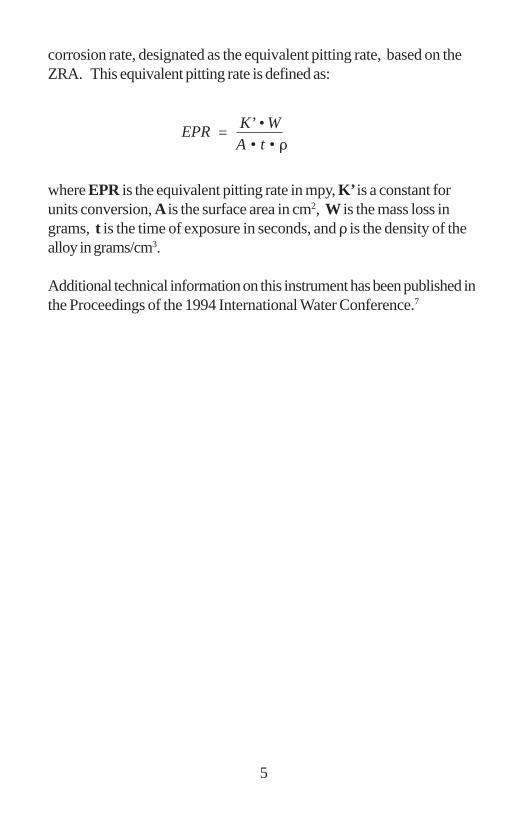
corrosion rate, designated as the equivalent pitting rate, based on theZRA. This equivalent pitting rate is defined as:
where EPR is the equivalent pitting rate in mpy, K’ is a constant forunits conversion, A is the surface area in cm2, W is the mass loss ingrams, t is the time of exposure in seconds, and is the density of thealloy in grams/cm3.
Additional technical information on this instrument has been published inthe Proceedings of the 1994 International Water Conference.7
EPR =K’ • WA • t •
5
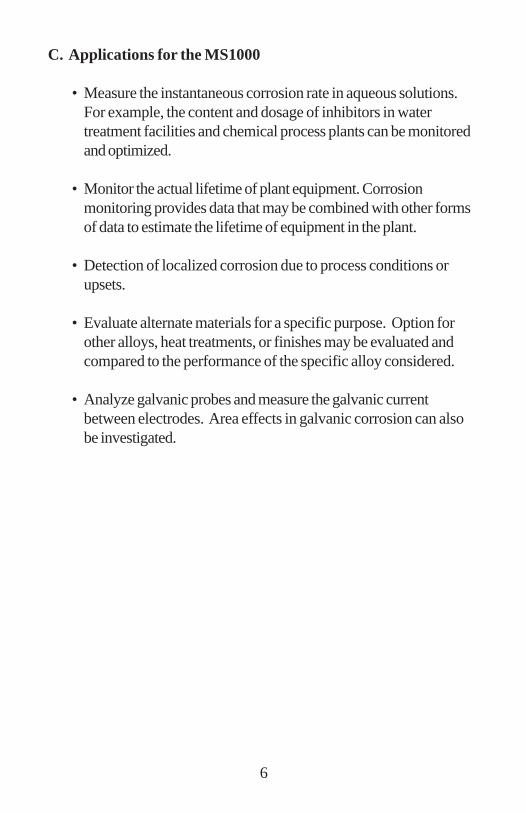
C. Applications for the MS1000
• Measure the instantaneous corrosion rate in aqueous solutions.For example, the content and dosage of inhibitors in watertreatment facilities and chemical process plants can be monitoredand optimized.
• Monitor the actual lifetime of plant equipment. Corrosionmonitoring provides data that may be combined with other formsof data to estimate the lifetime of equipment in the plant.
• Detection of localized corrosion due to process conditions orupsets.
• Evaluate alternate materials for a specific purpose. Option forother alloys, heat treatments, or finishes may be evaluated andcompared to the performance of the specific alloy considered.
• Analyze galvanic probes and measure the galvanic currentbetween electrodes. Area effects in galvanic corrosion can alsobe investigated.
6
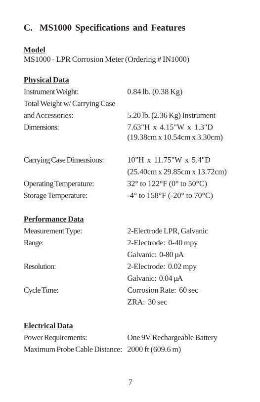
ModelMS1000 - LPR Corrosion Meter (Ordering # IN1000)
Physical Data
Instrument Weight: 0.84 lb. (0.38 Kg)
Total Weight w/ Carrying Case
and Accessories: 5.20 lb. (2.36 Kg) Instrument
Dimensions: 7.63"H x 4.15"W x 1.3"D(19.38cm x 10.54cm x 3.30cm)
Carrying Case Dimensions: 10"H x 11.75"W x 5.4"D
(25.40cm x 29.85cm x 13.72cm)
Operating Temperature: 32° to 122°F (0° to 50°C)
Storage Temperature: -4° to 158°F (-20° to 70°C)
Performance Data
Measurement Type: 2-Electrode LPR, Galvanic
Range: 2-Electrode: 0-40 mpy
Galvanic: 0-80 µA
Resolution: 2-Electrode: 0.02 mpy
Galvanic: 0.04 µA
Cycle Time: Corrosion Rate: 60 sec
ZRA: 30 sec
Electrical Data
Power Requirements: One 9V Rechargeable Battery
Maximum Probe Cable Distance: 2000 ft (609.6 m)
C. MS1000 Specifications and Features
7
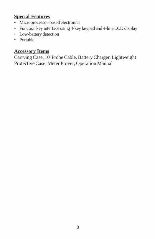
Special Features• Microprocessor-based electronics• Function key interface using 4-key keypad and 4-line LCD display• Low-battery detection• Portable
Accessory ItemsCarrying Case, 10' Probe Cable, Battery Charger, LightweightProtective Case, Meter Prover, Operation Manual
8
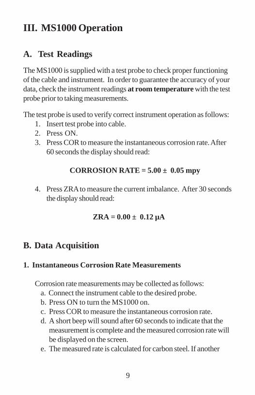
III. MS1000 Operation
A. Test Readings
The MS1000 is supplied with a test probe to check proper functioningof the cable and instrument. In order to guarantee the accuracy of yourdata, check the instrument readings at room temperature with the testprobe prior to taking measurements.
The test probe is used to verify correct instrument operation as follows:1. Insert test probe into cable.2. Press ON.3. Press COR to measure the instantaneous corrosion rate. After
60 seconds the display should read:
CORROSION RATE = 5.00 ± 0.05 mpy
4. Press ZRA to measure the current imbalance. After 30 secondsthe display should read:
ZRA = 0.00 ± 0.12 µA
B. Data Acquisition
1. Instantaneous Corrosion Rate Measurements
Corrosion rate measurements may be collected as follows:a. Connect the instrument cable to the desired probe.b. Press ON to turn the MS1000 on.c. Press COR to measure the instantaneous corrosion rate.d. A short beep will sound after 60 seconds to indicate that the
measurement is complete and the measured corrosion rate willbe displayed on the screen.
e. The measured rate is calculated for carbon steel. If another
9
electrode material was used, the result should be multiplied bythe appropriate alloy multiplier. Four common alloys are listedon the MS1000 keypad. A more comprehensive list isprovided on page 14.
2. ZRA and EPR Measurements
Electrochemical current noise and equivalent pitting rate measurementsmay be collected as follows:
a. Connect the instrument cable to the desired probe.b. Press ON to turn the MS1000 on.c. Press ZRA to measure the current imbalance between the
electrodes.d. A short beep will sound after 30 seconds to indicate that the
measurement is complete and the measured ZRA and EPR willbe displayed on the screen.
C. Electrode Installation, Replacement, and Care
The electrodes supplied from Metal Samples have a 600 grit (ground)surface finish. The electrodes are also degreased and shipped in volatilecorrosion inhibitor (vci) bags for protection. Additional cleaning of theelements prior to use is not required. However, it is recommended thatthe electrodes be pretreated in the test solution of interest in order tobring the electrode surfaces to equilibrium. Pretreatment may beconducted in a full strength mixture of the solution in the system. Typicalpretreatment times are at least 24 hours.
The resulting data generated from the pretreated electrodes will indicatethe corrosion trends of the system much more rapidly, usually within aday, as opposed to as much as a week for untreated electrodes.
10
New electrodes are 1.250" (31.75 mm) in length and 0.188" (4.76 mm)in diameter. As corrosion occurs, the electrode diameter decreases. Asa result, the electrode surface area decreases and the distance betweenthe electrodes increases. These two factors are sources of error andmay diminish the accuracy of the measured corrosion rate. Therefore, itis recommended that the electrodes be replaced when their diameterhas decreased by 17%. In other words, the electrodes should bereplaced when their diameter has decreased to 0.156" (3.97 mm).
If the probe and electrodes are to be moved, or if the electrodesbecome fouled with corrosion products or system contaminants,remove the electrodes from the probe and polish them to a dull shinewith wet 600 grit abrasive paper. After polishing, rinse and degreasethe electrodes prior to reinstallation.
Note: When handling electrodes, use clean latex gloves and papertowels. This will keep the electrodes clean and free from contaminatingoily deposits.
D. Correcting for Low Solution Conductivity Effects
Low solution conductivity effects increase the apparent polarizationresistance, thus yielding an underestimation of the corrosion rate. Theeffect of solution resistance is a function of the cell geometry. Since thecell geometry (in this case, the electrode configuration of the corrosionprobe) remains constant, analytical correction may be performed tocompensate for this apparent increase in the polarization resistance.The following equation may be used to approximate the magnitude ofthis effect.
Rp = R
a -
where Rp is the true polarization resistance, Ra is the apparent polariza-tion resistance as measured by the instrument, l is the distance between
l
11
the two electrodes in cm, and is the solution conductivity in ohms-1/cm. Specific guidelines for this correction technique are detailed inASTM G102.4
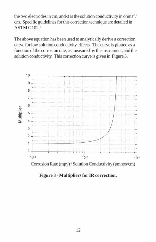
The above equation has been used to analytically derive a correctioncurve for low solution conductivity effects. The curve is plotted as afunction of the corrosion rate, as measured by the instrument, and thesolution conductivity. This correction curve is given in Figure 3.
Corrosion Rate (mpy) / Solution Conductivity (µmhos/cm)
Figure 3 - Multipliers for IR correction.
12
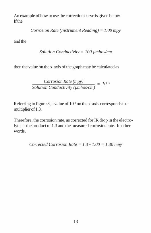
An example of how to use the correction curve is given below.If the
Corrosion Rate (Instrument Reading) = 1.00 mpy
Solution Conductivity = 100 µmhos/cm
and the
then the value on the x-axis of the graph may be calculated as
10 -2=Corrosion Rate (mpy)
Solution Conductivity (µmhos/cm)
Referring to figure 3, a value of 10-2 on the x-axis corresponds to amultiplier of 1.3.
Therefore, the corrosion rate, as corrected for IR drop in the electro-lyte, is the product of 1.3 and the measured corrosion rate. In otherwords,
Corrected Corrosion Rate = 1.3 • 1.00 = 1.30 mpy
13
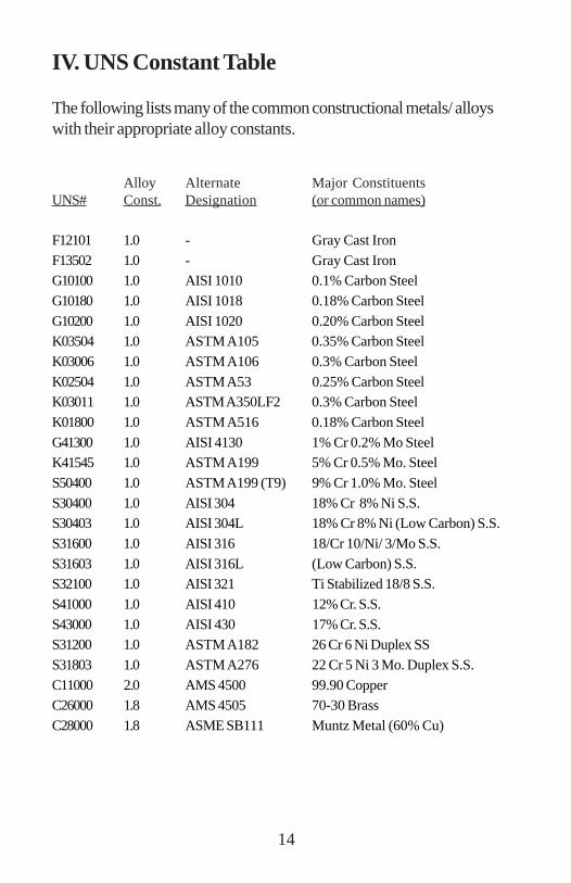
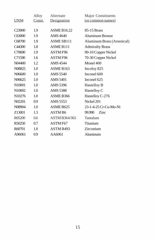
IV. UNS Constant Table
The following lists many of the common constructional metals/ alloyswith their appropriate alloy constants.
Alloy Alternate Major ConstituentsUNS# Const. Designation (or common names)
F12101 1.0 - Gray Cast Iron
F13502 1.0 - Gray Cast IronG10100 1.0 AISI 1010 0.1% Carbon Steel
G10180 1.0 AISI 1018 0.18% Carbon Steel
G10200 1.0 AISI 1020 0.20% Carbon SteelK03504 1.0 ASTM A105 0.35% Carbon Steel
K03006 1.0 ASTM A106 0.3% Carbon Steel
K02504 1.0 ASTM A53 0.25% Carbon SteelK03011 1.0 ASTM A350LF2 0.3% Carbon Steel
K01800 1.0 ASTM A516 0.18% Carbon Steel
G41300 1.0 AISI 4130 1% Cr 0.2% Mo SteelK41545 1.0 ASTM A199 5% Cr 0.5% Mo. Steel
S50400 1.0 ASTM A199 (T9) 9% Cr 1.0% Mo. Steel
S30400 1.0 AISI 304 18% Cr 8% Ni S.S.S30403 1.0 AISI 304L 18% Cr 8% Ni (Low Carbon) S.S.
S31600 1.0 AISI 316 18/Cr 10/Ni/ 3/Mo S.S.
S31603 1.0 AISI 316L (Low Carbon) S.S.S32100 1.0 AISI 321 Ti Stabilized 18/8 S.S.
S41000 1.0 AISI 410 12% Cr. S.S.
S43000 1.0 AISI 430 17% Cr. S.S.S31200 1.0 ASTM A182 26 Cr 6 Ni Duplex SS
S31803 1.0 ASTM A276 22 Cr 5 Ni 3 Mo. Duplex S.S.
C11000 2.0 AMS 4500 99.90 CopperC26000 1.8 AMS 4505 70-30 Brass
C28000 1.8 ASME SB111 Muntz Metal (60% Cu)
14
Alloy Alternate Major ConstituentsUNS# Const. Designation (or common names)
C23000 1.9 ASME B16.22 85-15 Brass
C63000 1.9 AMS 4640 Aluminum BronzeC68700 1.9 ASME SB111 Aluminum Brass (Arsenical)
C44300 1.8 ASME B111 Admiralty Brass
C70690 1.9 ASTM F96 90-10 Copper NickelC71590 1.6 ASTM F96 70-30 Copper Nickel
N04400 1.2 AMS 4544 Monel 400
N08825 1.0 ASME B163 Incoloy 825N06600 1.0 AMS 5540 Inconel 600
N06625 1.0 AMS 5401 Inconel 625
N10001 1.0 AMS 5396 Hastelloy BN10002 1.0 AMS 5388 Hastelloy C
N10276 1.0 ASME B366 Hastelloy C-276
N02201 0.9 AMS 5553 Nickel 201N08904 1.0 ASME B625 23-1-4-25 Cr-Cu-Mo-Ni
Z13001 1.3 ASTM B6 99.990 Zinc
R05200 0.6 ASTM B364/365 TantalumR50250 0.7 ASTM F67 Titanium
R60701 1.0 ASTM B493 Zirconium
A96061 0.9 AA6061 Aluminum
15
V. Maintenance
The only maintenance item in the MS1000 is the 9 volt rechargeablebattery. A battery charger is included with the instrument to facilitaterecharging. The battery will recharge to full capacity in a few hours.The LED indicator on the battery charger will turn red while the batteryis charging, and will turn green when the battery is fully charged. Overtime the rechargeable battery may require replacement. It should bereplaced with a rechargeable battery of the same type. Alternately, astandard alkaline battery can be installed, but you should NOT attemptto recharge it. Attempting to recharge an alkaline battery may cause it toleak and cause damage to the instrument.
VI. Troubleshooting
If the corrosion rate 5.00 ± 0.05 mpy when the calibration probeis connectedCheck the following items:
1. Is the calibration probe completely plugged into thecable assembly?
2. Is the cable assembly plugged into the “Probe” porton the instrument?
If the above methods do not cause the corrosion rate to be 5.00 ± 0.05mpy, it is possible that the cable assembly has been damaged. You maycheck the cable assembly for proper operation as follows:
1. Unplug the instrument from the power outlet and turn the powerswitch on the inside front panel to the “off” position.
2. Unplug the cable assembly from the “probe” connection on theinstrument.
3. Place a 1000 Ohm resistor across the bottom two pins of theprobe connector on the instrument OR use jumper wires and
16
connect pins A and D on the calibration probe directly to thelower two pins of the probe connector on the instrument.
You may plug the instrument into a power outlet, turn the instrument on,and then the measured corrosion rate should be 5.00 ± 0.05 mpy. Ifthe instrument does not calibrate properly, please contact MetalSamples.
17
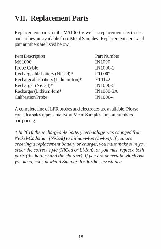
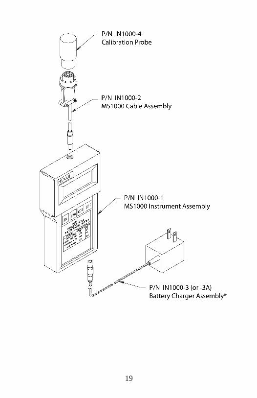
VII. Replacement Parts
Replacement parts for the MS1000 as well as replacement electrodesand probes are available from Metal Samples. Replacement items andpart numbers are listed below:
Item Description Part NumberMS1000 IN1000Probe Cable IN1000-2Rechargeable battery (NiCad)* ET0007Rechargeable battery (Lithium-Ion)* ET1142Recharger (NiCad)* IN1000-3Recharger (Lithium-Ion)* IN1000-3ACalibration Probe IN1000-4
A complete line of LPR probes and electrodes are available. Pleaseconsult a sales representative at Metal Samples for part numbersand pricing.
* In 2010 the rechargeable battery technology was changed fromNickel-Cadmium (NiCad) to Lithium-Ion (Li-Ion). If you areordering a replacement battery or charger, you must make sure youorder the correct style (NiCad or Li-Ion), or you must replace bothparts (the battery and the charger). If you are uncertain which oneyou need, consult Metal Samples for further assistance.
18
19
VIII. Warranty
Metal Samples will correct, either by repair or replacement, any defectof material or workmanship which develops within ninety (90) daysafter startup, or six (6) months from the date of shipment to the originalpurchaser, whichever comes first, provided that an inspection by MetalSamples discloses that such a defect developed under normal andproper use.
20
IX. References
1 “G-59: Standard Practice for Conducting Potentio-dynamic Polariza-tion Resistance Measurements”, 1993 Annual Book of ASTM Stan-dards, Vol. 3.02, Wear and Erosion: Metal Corrosion, ASTM, p. 219,(1993).
2 F. Mansfeld, Electrochemical Techniques for Corrosion Engineers,NACE, Houston, TX, p. 67-73 (1986).
3 F. Mansfeld, ASTM STP 727: Electrochemical Corrosion Testing, F.Mansfeld and U. Bertocci, Editors, ASTM, Philadelphia, PA, p. 163-262 (1981).
4 ASTM G102 Standard Practice for Calculation of Corrosion Rates &Related Information from Electrochemical Measurements, Annual Bookof ASTM Standards, Vol. 3.02, Wear and Erosion; Metal Corrosion,ASTM, Philadelphia, PA, p. 406-412, (1993).
5 M. Stern and A.L. Geary, J. Electrochem. Soc., 104, p. 57 (1957).
6 C.W. Wagner and W. Trand, Z. Electrochem., 44, p. 391 (1938).
7 J. Orth, Presented at the 1994 International Water Conference,Paper #IWC-94-10, (1994).
21