Embed Size (px)
Citation preview
Aalborg Universitet
A generic inertia emulation controller for multi-terminal VSC-HVDC systems
Zhu, Jiebei; Guerrero, Josep M.; Booth, Campbell; Zhang, Haotian; Adam, Grain
Published in:Proceedings of the 2nd IET Renewable Power Generation Conference (RPG 2013)
DOI (link to publication from Publisher):10.1049/cp.2013.1751
Publication date:2013
Document VersionEarly version, also known as pre-print
Link to publication from Aalborg University
Citation for published version (APA):Zhu, J., Guerrero, J. M., Booth, C., Zhang, H., & Adam, G. (2013). A generic inertia emulation controller formulti-terminal VSC-HVDC systems. In Proceedings of the 2nd IET Renewable Power Generation Conference(RPG 2013) Institution of Engineering and Technology. DOI: 10.1049/cp.2013.1751
General rightsCopyright and moral rights for the publications made accessible in the public portal are retained by the authors and/or other copyright ownersand it is a condition of accessing publications that users recognise and abide by the legal requirements associated with these rights.
? Users may download and print one copy of any publication from the public portal for the purpose of private study or research. ? You may not further distribute the material or use it for any profit-making activity or commercial gain ? You may freely distribute the URL identifying the publication in the public portal ?
Take down policyIf you believe that this document breaches copyright please contact us at [email protected] providing details, and we will remove access tothe work immediately and investigate your claim.
Downloaded from vbn.aau.dk on: august 17, 2018

A GENERIC INERTIA EMULATION CONTROLLER FOR MULTI-TERMINAL VSC-HVDC SYSTEMS
Jiebei Zhu*, Josep M. Guerrero†, Campbell D. Booth^, Haotian Zhang-, Grain P. Adam^
* National Grid,UK. Email:[email protected] †Aalborg University, Denmark. Email: [email protected]
^Unviersity of Strathclyde, UK..Email: [email protected]; [email protected] -City University London, UK. Email: [email protected]
Keywords: Frequency response, HVDC converters, HVDC transmission control.
Abstract A generic Inertia Emulation Controller (INEC) for Multi-
Terminal Voltage-source-converter based HVDC (VSC-MTDC) is proposed in this paper. The proposed INEC can be incorporated in any grid-side-voltage-source-converter (GVSC) station, allowing the MTDC terminal to contribute an inertial response during system disturbances, in a similar fashion with a synchronous generator. The DC link capacitors of MTDC are utilized by INEC to exchange the stored energy with the AC grid by varying the overall DC voltage level of the MTDC network. The derivation process of the INEC algorithm and its implementation to the conventional VSC control system are presented, and the impact of total DC capacitance of the MTDC network on DC voltage variations is discussed. The proposed INEC for MTDC systems are validated by Matlab/Simulink under demand changes in a simulated multi-machine power system with a MTDC transmission system, and the effectiveness of damping post-fault oscillations is also investigated.
1 Introduction The fast pace of renewable power generation development
raises many technical issues. The major concern associated with renewable power generation is their limited capability to participate system frequency management. Power system frequency is a global indicator of the active power generation and demand. Any short-term active power imbalance results an instantaneous rate of change of frequency, where system inertia plays an important role in determining the sensitivity of frequency deviation under these power imbalances. Higher
aggregated system inertia leads to higher frequency stability and security.
An increasing penetration of wind power generations together with conventional generation will degrade the frequency control performance. This is because of two reasons:
i) Typical wind turbine generators have lower inertia than classical power plants [1]. The “natural” inertial response is minimal;
ii) Most of wind turbine generators and other distributed generation (e.g. fuel cells, tidal and wave power) use power electronic interfaces and HVDC links, decoupling the kinetic energy available with prime movers [2].
To mitigate such a negative impact, many authors have investigated the possibility of using wind turbine generators to provide inertial and primary frequency response to the interfaced grids [1]-[4], and the possibility of HVDC transmission systems to dictate connected offshore wind farms to contribute inertia responses by means of communications [5] or without communications using physical DC cables as information channels [6]. However, these methods were all proposed to either operate wind power in reserved or de-loaded mode, which reduces the generation efficiency, or bother to drop wind turbine rotor speeds at frequency disturbances, which bring difficulties in restoring normal rotor speeds [4].
VSC-MTDC systems, as a topological expansion of point-to-point VSC-HVDC systems, are under development to address many technical and ecumenical problems [7], particularly for offshore wind farm integrations [9],[10]. A novel INEC strategy for VSC-HVDC transmission system was proposed using DC capacitor temporary storage capability in [8]. However, it did not cover the INEC implementation to a MTDC system and further work needs to be done as already stated in [8]. As a continuity of the initial
Fig. 1 Test scenario for the INEC implementation in the MTDC system
work in [8], this paper will extend the INEC application for point-to-point HVDC system to MTDC systems and study the system effect of the MTDC system with the INEC in a multi-machine power system as presented in Fig.1.
2 Modelling and control a MTDC system
2.1 Configuration
Fig. 1 presents a candidate MTDC configuration. In this case, there independent wind farms inject power into a ring DC network via converters WVSC1 and WVSC2. The converters GVSC1 and GVSC2 deliver power to AC power system on the right hand side. While the DC system is of a ring configuration, other DC network configurations type such as radial would be possible.
2.2 Control of grid side voltage source converter (GVSC)
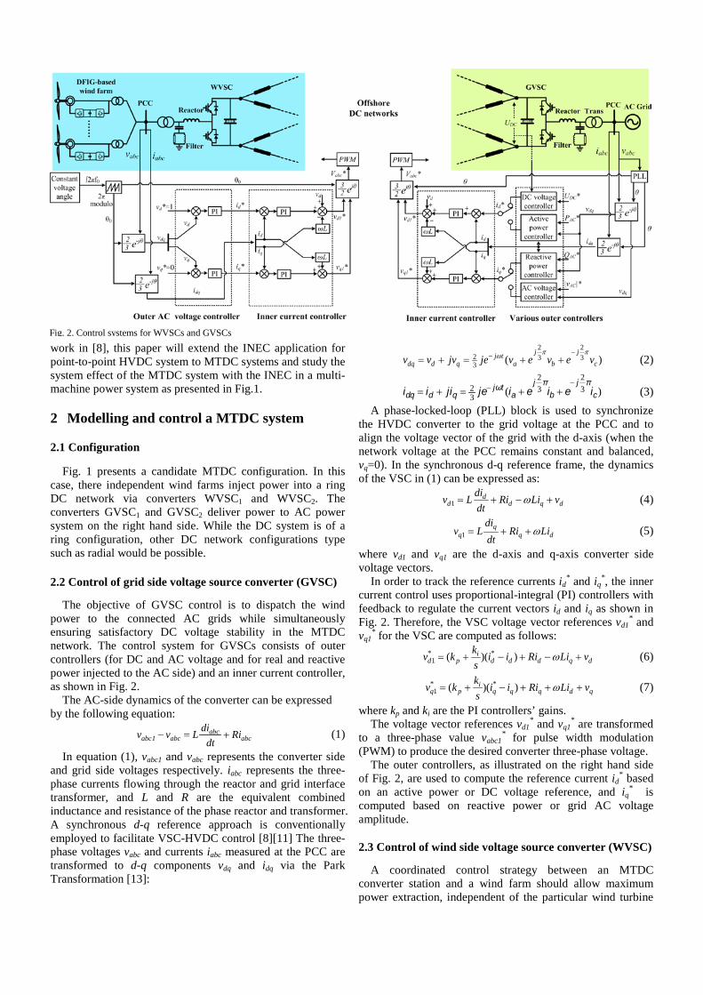
The objective of GVSC control is to dispatch the wind power to the connected AC grids while simultaneously ensuring satisfactory DC voltage stability in the MTDC network. The control system for GVSCs consists of outer controllers (for DC and AC voltage and for real and reactive power injected to the AC side) and an inner current controller, as shown in Fig. 2.
The AC-side dynamics of the converter can be expressed by the following equation:
abcabc1 abc abc
div v L Ridt
− = + (1)
In equation (1), vabc1 and vabc represents the converter side and grid side voltages respectively. iabc represents the three-phase currents flowing through the reactor and grid interface transformer, and L and R are the equivalent combined inductance and resistance of the phase reactor and transformer. A synchronous d-q reference approach is conventionally employed to facilitate VSC-HVDC control [8][11] The three-phase voltages vabc and currents iabc measured at the PCC are transformed to d-q components vdq and idq via the Park Transformation [13]:
2 22 3 33 ( )
−−= + = + +j jj t
dq d q a b cv v jv je v e v e vπ πω
(2)
)( 32
32
32
cj
bj
atj
qddq ieieijejiiiππω −− ++=+= (3)
A phase-locked-loop (PLL) block is used to synchronize the HVDC converter to the grid voltage at the PCC and to align the voltage vector of the grid with the d-axis (when the network voltage at the PCC remains constant and balanced, vq=0). In the synchronous d-q reference frame, the dynamics of the VSC in (1) can be expressed as:
1d
d d q ddiv L Ri Li vdt
ω= + − + (4)
1q
q q ddi
v L Ri Lidt
ω= + + (5)
where vd1 and vq1 are the d-axis and q-axis converter side voltage vectors.
In order to track the reference currents id* and iq
*, the inner current control uses proportional-integral (PI) controllers with feedback to regulate the current vectors id and iq as shown in Fig. 2. Therefore, the VSC voltage vector references vd1
* and vq1
* for the VSC are computed as follows: * *
1 ( )( )id p d d d q d
kv k i i Ri Li vs
ω= + − + − + (6)
* *1 ( )( )i
q p q q q d qkv k i i Ri Li vs
ω= + − + + + (7)
where kp and ki are the PI controllers’ gains. The voltage vector references vd1
* and vq1* are transformed
to a three-phase value vabc1* for pulse width modulation
(PWM) to produce the desired converter three-phase voltage. The outer controllers, as illustrated on the right hand side
of Fig. 2, are used to compute the reference current id* based
on an active power or DC voltage reference, and iq* is
computed based on reactive power or grid AC voltage amplitude.
2.3 Control of wind side voltage source converter (WVSC)
A coordinated control strategy between an MTDC converter station and a wind farm should allow maximum power extraction, independent of the particular wind turbine
Fig. 2. Control systems for WVSCs and GVSCs
generators employed. In [11], grid integration of a doubly-fed-induction-generator-based (DFIG) wind farm using a VSC-HVDC system is studied. The control of the wind farm is based on maximum power point tracking (MPPT), which formulates wind power-versus-turbine speed characteristics at different wind speeds [8]-[11]. A WVSC of the HVDC transmission system provides constant frequency and voltage amplitude for the wind farm network. As long as the frequency and AC voltage amplitude are maintained constant, the power generated by the wind farm is automatically absorbed by the WVSC and transferred to the DC link [11].
The WVSC should act as an AC voltage source with a constant frequency for wind farm integration. The control systems for WVSC proposed in [8]-[12] regulate frequency via a modulation index without use of inner current control. However, the disadvantage for this type of control is that the current through the WVSC is not effectively controlled due to the absence of the inner current control, which may stress the converter.
In this paper, the inner current control, as is the case with the GVSC controllers described in Section II B, is employed in order to provide a secure means of current control for WVSC operation. By regulating the AC voltage amplitude component vd with a target value of 1 pu and the phase angle voltage component vq with a target of 0, the the WVSC can act as a “stiff” voltage source and idq* for the inner current control is generated. A constant phase angle θ0 is provided for the Park and inverse Park transformations by a fixed PLL which uses grid frequency f0 (e.g. 50 Hz) as a constant input, as illustrated in Fig. 2.
3 Inertia emulation controller for MTDC VSCs
3.1 Derivation process of the INEC algorithm [8]
In order to emulate a specific inertia time constant HVSC, the DC voltage level in VSC-HVDC link must vary according to the AC network frequency, although the variation will be non-linear. A large value of HVSC will require a correspondingly large variation in DC voltage and this must be considered in the design of the VSC-HVDC system. The relationship between the emulated VSC inertia time constants and DC voltage variations is derived in [8] as follows:
0
2
0
20
2
1121
ff
VV
SVNC
HDC
DC
VSC
DC
VSC ∆⋅
−
+
∆⋅⋅
= (8)
where HVSC is the emulated VSC inertia time constant, N is the total number of capacitors in MTDC network, C is the individual capacitance for the capacitors, VDC0 is the nominal DC voltage level for the MTDC system, ∆VDC is the DC voltage change, SVSC is the VSC rated MVA power, f0 is the nominal grid frequency, and ∆f is the grid frequency change at disturbances.
3.2 INEC implementation to MTDC systems
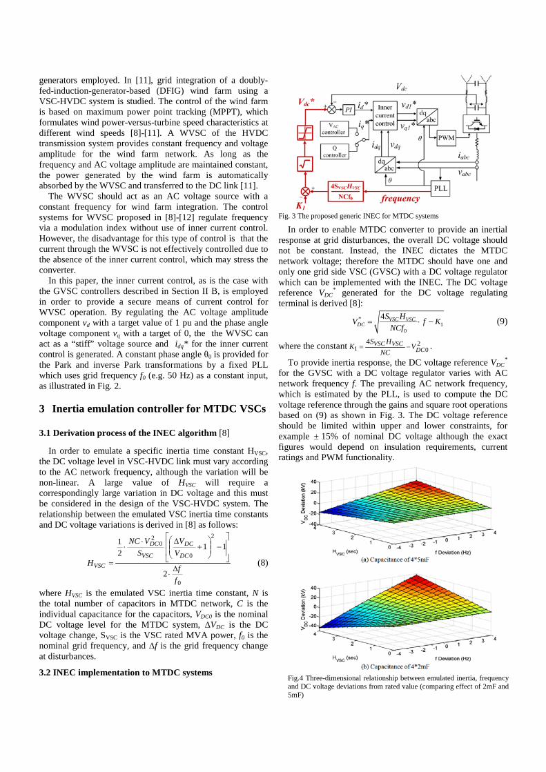
In order to enable MTDC converter to provide an inertial
response at grid disturbances, the overall DC voltage should not be constant. Instead, the INEC dictates the MTDC network voltage; therefore the MTDC should have one and only one grid side VSC (GVSC) with a DC voltage regulator which can be implemented with the INEC. The DC voltage reference VDC
* generated for the DC voltage regulating terminal is derived [8]:
*1
0
4 VSC VSCDC
S HV f KNCf
= ⋅ −
(9)
where the constant 201
4DC
VSCVSC VNC
HSK −= .
To provide inertia response, the DC voltage reference VDC*
for the GVSC with a DC voltage regulator varies with AC network frequency f. The prevailing AC network frequency, which is estimated by the PLL, is used to compute the DC voltage reference through the gains and square root operations based on (9) as shown in Fig. 3. The DC voltage reference should be limited within upper and lower constraints, for example ± 15% of nominal DC voltage although the exact figures would depend on insulation requirements, current ratings and PWM functionality.
Fig.4 Three-dimensional relationship between emulated inertia, frequency and DC voltage deviations from rated value (comparing effect of 2mF and 5mF)
Fig. 3 The proposed generic INEC for MTDC systems
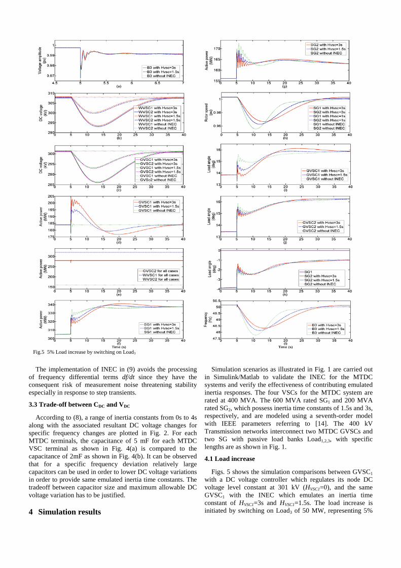
Fig.5 5% Load increase by switching on Load3
The implementation of INEC in (9) avoids the processing of frequency differential terms df/dt since they have the consequent risk of measurement noise threatening stability especially in response to step transients.
3.3 Trade-off between CDC and VDC
According to (8), a range of inertia constants from 0s to 4s along with the associated resultant DC voltage changes for specific frequency changes are plotted in Fig. 2. For each MTDC terminals, the capacitance of 5 mF for each MTDC VSC terminal as shown in Fig. 4(a) is compared to the capacitance of 2mF as shown in Fig. 4(b). It can be observed that for a specific frequency deviation relatively large capacitors can be used in order to lower DC voltage variations in order to provide same emulated inertia time constants. The tradeoff between capacitor size and maximum allowable DC voltage variation has to be justified.
4 Simulation results
Simulation scenarios as illustrated in Fig. 1 are carried out in Simulink/Matlab to validate the INEC for the MTDC systems and verify the effectiveness of contributing emulated inertia responses. The four VSCs for the MTDC system are rated at 400 MVA. The 600 MVA rated SG1 and 200 MVA rated SG2, which possess inertia time constants of 1.5s and 3s, respectively, and are modeled using a seventh-order model with IEEE parameters referring to [14]. The 400 kV Transmission networks interconnect two MTDC GVSCs and two SG with passive load banks Load1,2,3, with specific lengths are as shown in Fig. 1.
4.1 Load increase
Figs. 5 shows the simulation comparisons between GVSC1 with a DC voltage controller which regulates its node DC voltage level constant at 301 kV (HVSC1=0), and the same GVSC1 with the INEC which emulates an inertia time constant of HVSC1=3s and HVSC1=1.5s. The load increase is initiated by switching on Load3 of 50 MW, representing 5%
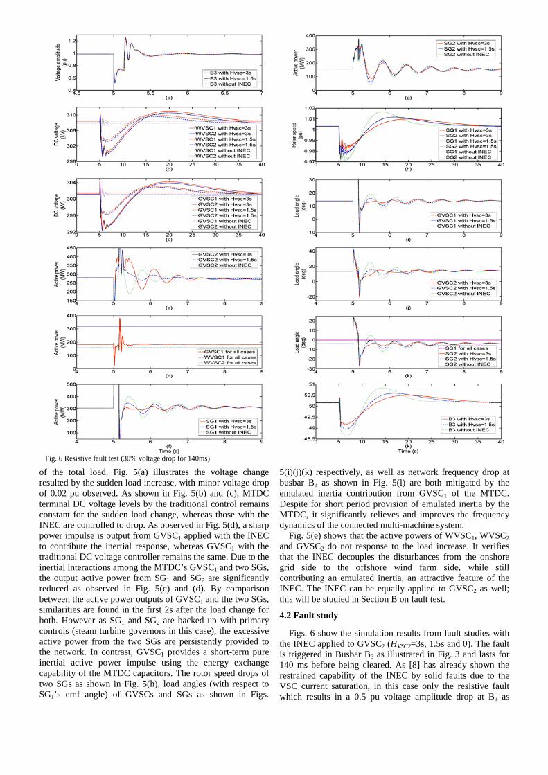
Fig. 6 Resistive fault test (30% voltage drop for 140ms)
of the total load. Fig. 5(a) illustrates the voltage change resulted by the sudden load increase, with minor voltage drop of 0.02 pu observed. As shown in Fig. 5(b) and (c), MTDC terminal DC voltage levels by the traditional control remains constant for the sudden load change, whereas those with the INEC are controlled to drop. As observed in Fig. 5(d), a sharp power impulse is output from GVSC1 applied with the INEC to contribute the inertial response, whereas GVSC1 with the traditional DC voltage controller remains the same. Due to the inertial interactions among the MTDC’s GVSC1 and two SGs, the output active power from SG1 and SG2 are significantly reduced as observed in Fig. 5(c) and (d). By comparison between the active power outputs of GVSC1 and the two SGs, similarities are found in the first 2s after the load change for both. However as SG1 and SG2 are backed up with primary controls (steam turbine governors in this case), the excessive active power from the two SGs are persistently provided to the network. In contrast, GVSC1 provides a short-term pure inertial active power impulse using the energy exchange capability of the MTDC capacitors. The rotor speed drops of two SGs as shown in Fig. 5(h), load angles (with respect to SG1’s emf angle) of GVSCs and SGs as shown in Figs.
5(i)(j)(k) respectively, as well as network frequency drop at busbar B3 as shown in Fig. 5(l) are both mitigated by the emulated inertia contribution from GVSC1 of the MTDC. Despite for short period provision of emulated inertia by the MTDC, it significantly relieves and improves the frequency dynamics of the connected multi-machine system.
Fig. 5(e) shows that the active powers of WVSC1, WVSC2 and GVSC2 do not response to the load increase. It verifies that the INEC decouples the disturbances from the onshore grid side to the offshore wind farm side, while still contributing an emulated inertia, an attractive feature of the INEC. The INEC can be equally applied to GVSC2 as well; this will be studied in Section B on fault test.
4.2 Fault study
Figs. 6 show the simulation results from fault studies with the INEC applied to GVSC2 (HVSC2=3s, 1.5s and 0). The fault is triggered in Busbar B3 as illustrated in Fig. 3 and lasts for 140 ms before being cleared. As [8] has already shown the restrained capability of the INEC by solid faults due to the VSC current saturation, in this case only the resistive fault which results in a 0.5 pu voltage amplitude drop at B3 as
shown in Fig. 6(a), is studied. It is clearly shown in Fig. 6(b) and (c) that DC voltage
levels for four VSC nodes are not affected by the fault by the traditional control, whereas those with GVSC2 dedicated with HVSC2=3s and HVSC=1.5s as shown in Fig. 6 are both varied. Through the active power interactions between GVSC2 and two SGs as shown in Figs. 6(d)(f)(g) respectively, the rotor speed variations and frequency variations at busbar B3, as illustrated in Fig. 6(h) and (k) respectively, are significantly damped and postponed by larger emulated inertia provided by GVSC2. The lower degree in load angle variations for the case with HVSC2=3s than those with HVSC2=1.5s and 0, observed in Figs. 6(i)(j)(h) verify the stabilizing effect of the INEC for the fault test. This is believed that the GVSCs with the INEC manage to interact and count-balance the transient and dynamic changes resulted by the fault. The active power of WVSC1, WVSC2 and GVSC1 remain the same for three cases, as shown in Fig. 6(e).
5 Simulation results This paper proposes a generic inertia emulation controller
(INEC) for multi-terminal HVDC (MTDC) transmission system, as a follow-up work of the INEC for point-to-point HVDC systems presented in [8]. The INEC allows a random MTDC grid side converter to contribute an inertial response, by varying DC voltage levels to exchange the electro-static energy stored in DC link capacitors with an AC grid, without modification on MTDC hardware. By validating, verifying and comparing in the simulations, it has the following features:
-Interconnected synchronous generators’ rotor speed variations during system disturbances (e.g. demand changes, temporary faults) are effectively damped by the INEC;
-Power network frequency deviations as well as busbar load angle deviations during system disturbances are effectively stabilized by the INEC;
-The INEC still keeps the decoupling feature of VSCs, which isolate the grid disturbances from offshore weak power systems.
Appendix
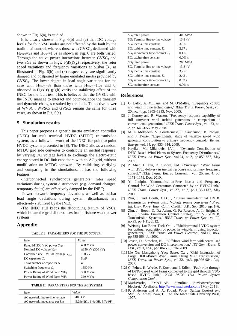
TABLE I PARAMETERS FOR THE DC SYSTEM
Item Value Rated MTDC VSC power SVSC 400 MVA Nominal DC voltage VDC0 ±150 kV (300 kV) Converter side RMS AC voltage VAC0 150 kV DC capacitor Cdc 5mF Total number of capacitor N 4 Switching frequency fsw 1350 Hz Power Rating of Wind Farm WF1 380 MVA Power Rating of Wind Farm WF2 360 MVA
TABLE II PARAMETERS FOR THE AC SYSTEM
Item Value AC network line-to-line voltage 400 kV AC network impedance per km 5.29e-2Ω , 1.4e-3H, 8.7e-9F
SG1 rated power 400 MVA SG1 Terminal line-to-line voltage 13.8 kV SG1 inertia time constant 3.3 s SG1 turbine time constant Tw 2.67 s SG1 servomotor time constant Ta 0.1 s SG1 exciter time constant 0.001 s SG2 rated power 200 MVA SG2 Terminal line-to-line voltage 13.8 kV SG2 inertia time constant 3.2 s SG2 turbine time constant Tw 2.43 s SG2 servomotor time constant Ta 0.07 s SG2 exciter time constant 0.001 s
References [1] G. Lalor, A. Mullane, and M. O’Malley, “Frequency control
and wind turbine technologies,” IEEE Trans. Power. Syst., vol. 20, no. 4, pp. 1905–1913, Nov. 2005.
[2] J. Conroy and R. Watson, “Frequency response capability of full converter wind turbine generators in comparison to conventional generation,” IEEE Trans. Power Syst., vol. 23, no. 2, pp. 649–656, May 2008.
[3] M. E. Mokadem, V. Courtecuisse, C. Saudemont, B. Robyns, and J. Deuse, “Experimental study of variable speed wind generator contribution to primary frequency control,” Renew. Energy, vol. 34, pp. 833–844, 2009.
[4] Kayikci, M.; Milanovic, J.V.; , "Dynamic Contribution of DFIG-Based Wind Plants to System Frequency Disturbances," IEEE Trans. on Power Syst., vol.24, no.2, pp.859-867, May 2009.
[5] Z. Miao, L. Fan, D. Osborn, and S.Yuvarajan, “Wind farms with HVdc delivery in inertial response and primary frequency control,” IEEE Trans. Energy Convers. , vol. 25, no. 4, pp. 1171–1178, Dec. 2010.
[6] Y. Phulpin, "Communication-Free Inertia and Frequency Control for Wind Generators Connected by an HVDC-Link," IEEE Trans. Power Syst., vol.27, no.2, pp.1136-1137, May 2012.
[7] Zhu, J. and Booth, C.D.; , "Future multi-terminal HVDC transmission systems using Voltage source converters," Proc. Int. Univ. Power Eng., Conf., Cardiff, U.K., Sep. 2010, pp. 1–6.
[8] Zhu, J.; Booth, C. D.; Adam, G. P.; Roscoe, A. J.; Bright, C. G.; , "Inertia Emulation Control Strategy for VSC-HVDC Transmission Systems," IEEE Trans. on Power Syst., vol.PP, no.99, pp.1-11, 2012.
[9] Weixing Lu; Boon Teck Ooi; , "Multiterminal LVDC system for optimal acquisition of power in wind-farm using induction generators," IEEE Trans. on Power Electron., vol.17, no.4, pp.558-563, Jul 2002.
[10] Jovcic, D.; Strachan, N.; , "Offshore wind farm with centralised power conversion and DC interconnection," IET Gen., Trans. & Dist., vol.3, no.6, pp.586-595, June 2009.
[11] Lie Xu; Liangzhong Yao; Sasse, C.; , "Grid Integration of Large DFIG-Based Wind Farms Using VSC Transmission," IEEE Trans. on Power Syst., vol.22, no.3, pp.976-984, Aug. 2007.
[12] C. Feltes, H. Wrede, F. Koch, and I. Erlich, “Fault ride-through of DFIG-based wind farms connected to the grid through VSC-based HVDC link,” 2008 PSCC 16th Power System Computation Conf..
[13] MathWorks, "MATLAB Simulink SimPowerSystems blockset," Available: http://www.mathworks.com/ [May 2011].
[14] P. Anderson and A. A. Fouad, Power System Control and Stability. Ames, Iowa, U.S.A: The Iowa State Univerity Press, 1977.