Embed Size (px)
Citation preview
Aalborg Universitet
Benchmarking of Voltage Sag Generators
Yang, Yongheng; Blaabjerg, Frede; Zou, Zhixiang
Published in:the 38th Annual Conference of the IEEE Industrial Electronics Society
DOI (link to publication from Publisher):10.1109/IECON.2012.6389164
Publication date:2012
Document VersionEarly version, also known as pre-print
Link to publication from Aalborg University
Citation for published version (APA):Yang, Y., Blaabjerg, F., & Zou, Z. (2012). Benchmarking of Voltage Sag Generators. In the 38th AnnualConference of the IEEE Industrial Electronics Society (pp. 943-948). Montreal: IEEE Press. I E E E IndustrialElectronics Society. Annual Conference. Proceedings, DOI: 10.1109/IECON.2012.6389164
General rightsCopyright and moral rights for the publications made accessible in the public portal are retained by the authors and/or other copyright ownersand it is a condition of accessing publications that users recognise and abide by the legal requirements associated with these rights.
? Users may download and print one copy of any publication from the public portal for the purpose of private study or research. ? You may not further distribute the material or use it for any profit-making activity or commercial gain ? You may freely distribute the URL identifying the publication in the public portal ?
Take down policyIf you believe that this document breaches copyright please contact us at [email protected] providing details, and we will remove access tothe work immediately and investigate your claim.
Downloaded from vbn.aau.dk on: juli 03, 2018
Benchmarking of Voltage Sag GeneratorsYongheng Yang, Frede BlaabjergDepartment of Energy Technology
Aalborg UniversityPontoppidanstraede 101, Aalborg DK-9220, Denmark
[email protected], [email protected]
Zhixiang ZouSchool of Electrical Engineering
Southeast UniversityNo. 2 Sipailou, Nanjing 210096, China
Abstract—The increased penetration of renewable energy sys-tems, like photovoltaic and wind power systems, rises the concernabout the power quality and stability of the utility grid. Someregulations for Low Voltage Ride-Through (LVRT) for mediumvoltage or high voltage applications, are coming into force toguide these grid-connected distributed power generation systems.In order to verify the response of such systems for voltagedisturbance, mainly for evaluation of voltage sags/dips, a VoltageSag Generator (VSG) is needed. This paper evaluates such sagtest devices according to IEC 61000 in order to provide cheapersolutions to test against voltage sags. Simulation and experimentalresults demonstrate that the shunt impedance based VSG solutionis the easiest and cheapest one for laboratory test applications.The back-to-back fully controlled converter based VSG is themost flexible solution for the system test under grid faults butalso the most expensive one.
I. INTRODUCTION
The highly increased penetration of renewable energy sys-tems, especially photovoltaic (PV) systems and wind turbine(WT) power systems, stirs up research on the integrationand control of such environmentally-friendly power generationunits. However, it may also cause some negative impact onthe power quality, stability and availability of public grids.Some national grid codes, mainly fault ride-through and gridsupport capabilities, have been issued by the TransmissionSystem Operator (TSO) to regulate the distributed generationsconnected to medium-voltage or high-voltage networks [1].These requirements are also expected to be updated for low-voltage level applications, because the impact of the fastgrowth of distributed generation systems, especially PV sys-tems, connected to low-voltage grids can not be neglected atthis level either.
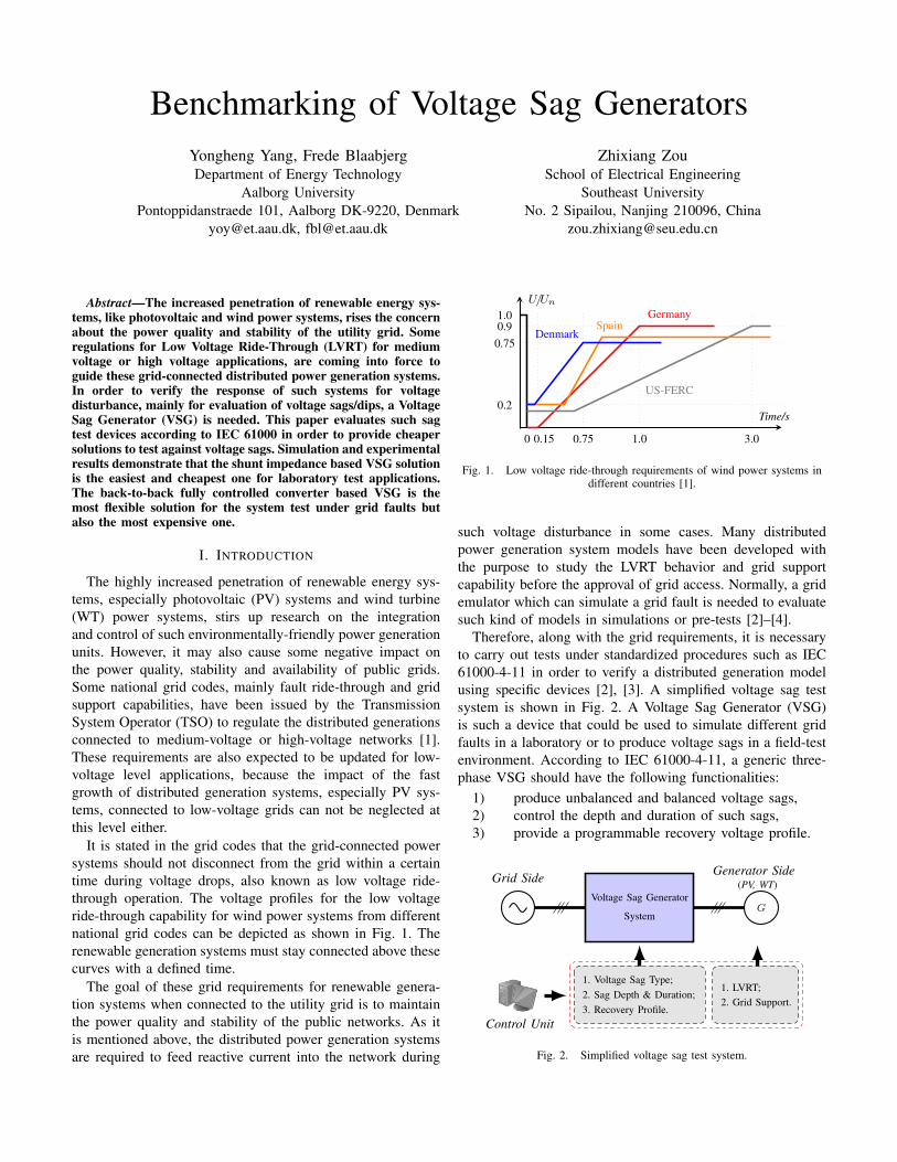
It is stated in the grid codes that the grid-connected powersystems should not disconnect from the grid within a certaintime during voltage drops, also known as low voltage ride-through operation. The voltage profiles for the low voltageride-through capability for wind power systems from differentnational grid codes can be depicted as shown in Fig. 1. Therenewable generation systems must stay connected above thesecurves with a defined time.
The goal of these grid requirements for renewable genera-tion systems when connected to the utility grid is to maintainthe power quality and stability of the public networks. As itis mentioned above, the distributed power generation systemsare required to feed reactive current into the network during
Time/s
0 0.15 0.75 1.0 3.0
U/Un
1.00.9
0.75
0.2
Germany
US-FERC
SpainDenmark
Fig. 1. Low voltage ride-through requirements of wind power systems indifferent countries [1].
such voltage disturbance in some cases. Many distributedpower generation system models have been developed withthe purpose to study the LVRT behavior and grid supportcapability before the approval of grid access. Normally, a gridemulator which can simulate a grid fault is needed to evaluatesuch kind of models in simulations or pre-tests [2]–[4].
Therefore, along with the grid requirements, it is necessaryto carry out tests under standardized procedures such as IEC61000-4-11 in order to verify a distributed generation modelusing specific devices [2], [3]. A simplified voltage sag testsystem is shown in Fig. 2. A Voltage Sag Generator (VSG)is such a device that could be used to simulate different gridfaults in a laboratory or to produce voltage sags in a field-testenvironment. According to IEC 61000-4-11, a generic three-phase VSG should have the following functionalities:
1) produce unbalanced and balanced voltage sags,2) control the depth and duration of such sags,3) provide a programmable recovery voltage profile.
GVoltage Sag Generator
System
Grid Side Generator Side(PV, WT)
1. Voltage Sag Type;1. LVRT;
2. Sag Depth & Duration;2. Grid Support.
3. Recovery Profile.Control Unit
Fig. 2. Simplified voltage sag test system.
The scope of this paper is first to give a thorough descriptionof the existing VSG topologies, followed by a discussion ofbidirectional switches which are commonly used in a VSGsystem. With the purpose to provide cheaper solutions to testagainst voltage sags, the focus will be put on a comparisonof these voltage sag generators based on the simulation andexperimental results in terms of performance and cost. Finally,a single-phase system is demonstrated in grid faulty modeoperation.
II. VOLTAGE SAG GENERATOR SOLUTIONS
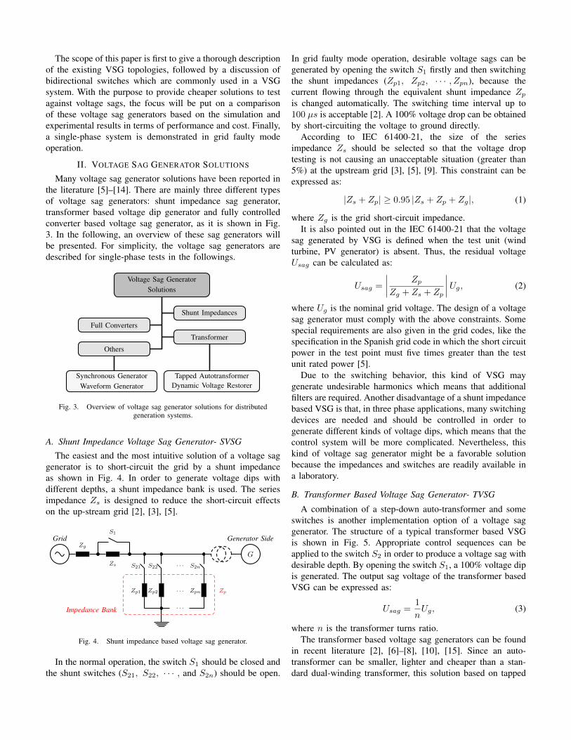
Many voltage sag generator solutions have been reported inthe literature [5]–[14]. There are mainly three different typesof voltage sag generators: shunt impedance sag generator,transformer based voltage dip generator and fully controlledconverter based voltage sag generator, as it is shown in Fig.3. In the following, an overview of these sag generators willbe presented. For simplicity, the voltage sag generators aredescribed for single-phase tests in the followings.
Voltage Sag GeneratorSolutions
Shunt Impedances
Full Converters
Transformer
Others
Dynamic Voltage RestorerTapped Autotransformer
Waveform GeneratorSynchronous Generator
Fig. 3. Overview of voltage sag generator solutions for distributedgeneration systems.
A. Shunt Impedance Voltage Sag Generator- SVSG
The easiest and the most intuitive solution of a voltage saggenerator is to short-circuit the grid by a shunt impedanceas shown in Fig. 4. In order to generate voltage dips withdifferent depths, a shunt impedance bank is used. The seriesimpedance Zs is designed to reduce the short-circuit effectson the up-stream grid [2], [3], [5].
Zg
G
· · ·
Grid Generator SideS1
Zs S21
Zp1
S22
Zp2
S2n
Zpn
· · ·
· · ·
Impedance Bank
Zp
Fig. 4. Shunt impedance based voltage sag generator.
In the normal operation, the switch S1 should be closed andthe shunt switches (S21, S22, · · · , and S2n) should be open.
In grid faulty mode operation, desirable voltage sags can begenerated by opening the switch S1 firstly and then switchingthe shunt impedances (Zp1, Zp2, · · · , Zpn), because thecurrent flowing through the equivalent shunt impedance Zp
is changed automatically. The switching time interval up to100 µs is acceptable [2]. A 100% voltage drop can be obtainedby short-circuiting the voltage to ground directly.
According to IEC 61400-21, the size of the seriesimpedance Zs should be selected so that the voltage droptesting is not causing an unacceptable situation (greater than5%) at the upstream grid [3], [5], [9]. This constraint can beexpressed as:
|Zs + Zp| ≥ 0.95 |Zs + Zp + Zg|, (1)
where Zg is the grid short-circuit impedance.It is also pointed out in the IEC 61400-21 that the voltage
sag generated by VSG is defined when the test unit (windturbine, PV generator) is absent. Thus, the residual voltageUsag can be calculated as:
Usag =
∣∣∣∣ Zp
Zg + Zs + Zp
∣∣∣∣Ug, (2)
where Ug is the nominal grid voltage. The design of a voltagesag generator must comply with the above constraints. Somespecial requirements are also given in the grid codes, like thespecification in the Spanish grid code in which the short circuitpower in the test point must five times greater than the testunit rated power [5].
Due to the switching behavior, this kind of VSG maygenerate undesirable harmonics which means that additionalfilters are required. Another disadvantage of a shunt impedancebased VSG is that, in three phase applications, many switchingdevices are needed and should be controlled in order togenerate different kinds of voltage dips, which means that thecontrol system will be more complicated. Nevertheless, thiskind of voltage sag generator might be a favorable solutionbecause the impedances and switches are readily available ina laboratory.
B. Transformer Based Voltage Sag Generator- TVSG
A combination of a step-down auto-transformer and someswitches is another implementation option of a voltage saggenerator. The structure of a typical transformer based VSGis shown in Fig. 5. Appropriate control sequences can beapplied to the switch S2 in order to produce a voltage sag withdesirable depth. By opening the switch S1, a 100% voltage dipis generated. The output sag voltage of the transformer basedVSG can be expressed as:
Usag =1
nUg, (3)
where n is the transformer turns ratio.The transformer based voltage sag generators can be found
in recent literature [2], [6]–[8], [10], [15]. Since an auto-transformer can be smaller, lighter and cheaper than a stan-dard dual-winding transformer, this solution based on tapped
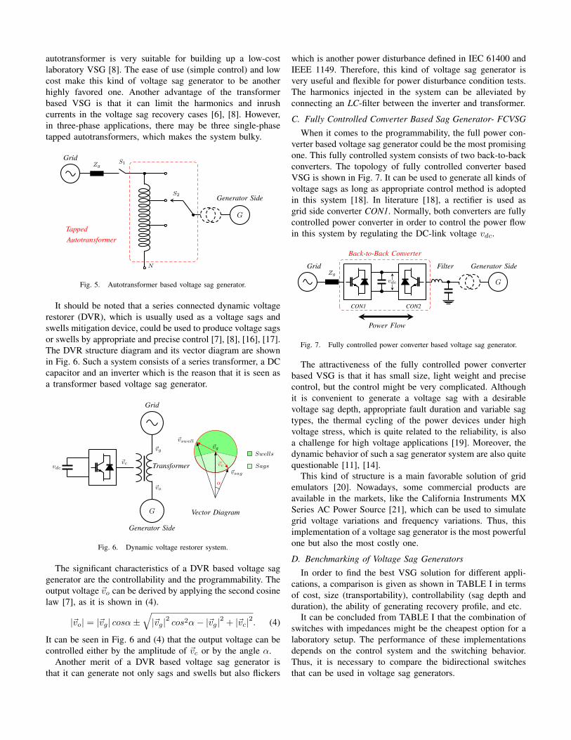
autotransformer is very suitable for building up a low-costlaboratory VSG [8]. The ease of use (simple control) and lowcost make this kind of voltage sag generator to be anotherhighly favored one. Another advantage of the transformerbased VSG is that it can limit the harmonics and inrushcurrents in the voltage sag recovery cases [6], [8]. However,in three-phase applications, there may be three single-phasetapped autotransformers, which makes the system bulky.
Zg
G
GridS1
Generator SideS2
N
TappedAutotransformer
Fig. 5. Autotransformer based voltage sag generator.
It should be noted that a series connected dynamic voltagerestorer (DVR), which is usually used as a voltage sags andswells mitigation device, could be used to produce voltage sagsor swells by appropriate and precise control [7], [8], [16], [17].The DVR structure diagram and its vector diagram are shownin Fig. 6. Such a system consists of a series transformer, a DCcapacitor and an inverter which is the reason that it is seen asa transformer based voltage sag generator.
vdc
G
Grid
Generator Side
~vg
~vc Transformer
~vo
Vector Diagram
α
~vg
~vc
~vswell
~vsag
Swells
Sags
Fig. 6. Dynamic voltage restorer system.
The significant characteristics of a DVR based voltage saggenerator are the controllability and the programmability. Theoutput voltage ~vo can be derived by applying the second cosinelaw [7], as it is shown in (4).
|~vo| = |~vg| cosα±√|~vg|2 cos2α− |~vg|2 + |~vc|2. (4)
It can be seen in Fig. 6 and (4) that the output voltage can becontrolled either by the amplitude of ~vc or by the angle α.
Another merit of a DVR based voltage sag generator isthat it can generate not only sags and swells but also flickers
which is another power disturbance defined in IEC 61400 andIEEE 1149. Therefore, this kind of voltage sag generator isvery useful and flexible for power disturbance condition tests.The harmonics injected in the system can be alleviated byconnecting an LC-filter between the inverter and transformer.
C. Fully Controlled Converter Based Sag Generator- FCVSGWhen it comes to the programmability, the full power con-
verter based voltage sag generator could be the most promisingone. This fully controlled system consists of two back-to-backconverters. The topology of fully controlled converter basedVSG is shown in Fig. 7. It can be used to generate all kinds ofvoltage sags as long as appropriate control method is adoptedin this system [18]. In literature [18], a rectifier is used asgrid side converter CON1. Normally, both converters are fullycontrolled power converter in order to control the power flowin this system by regulating the DC-link voltage vdc.
Zg
Gvdc
Grid Generator SideFilter
CON1 CON2
Back-to-Back Converter
Power Flow
Fig. 7. Fully controlled power converter based voltage sag generator.
The attractiveness of the fully controlled power converterbased VSG is that it has small size, light weight and precisecontrol, but the control might be very complicated. Althoughit is convenient to generate a voltage sag with a desirablevoltage sag depth, appropriate fault duration and variable sagtypes, the thermal cycling of the power devices under highvoltage stress, which is quite related to the reliability, is alsoa challenge for high voltage applications [19]. Moreover, thedynamic behavior of such a sag generator system are also quitequestionable [11], [14].
This kind of structure is a main favorable solution of gridemulators [20]. Nowadays, some commercial products areavailable in the markets, like the California Instruments MXSeries AC Power Source [21], which can be used to simulategrid voltage variations and frequency variations. Thus, thisimplementation of a voltage sag generator is the most powerfulone but also the most costly one.
D. Benchmarking of Voltage Sag GeneratorsIn order to find the best VSG solution for different appli-
cations, a comparison is given as shown in TABLE I in termsof cost, size (transportability), controllability (sag depth andduration), the ability of generating recovery profile, and etc.
It can be concluded from TABLE I that the combination ofswitches with impedances might be the cheapest option for alaboratory setup. The performance of these implementationsdepends on the control system and the switching behavior.Thus, it is necessary to compare the bidirectional switchesthat can be used in voltage sag generators.
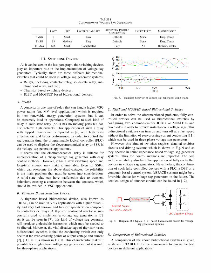
TABLE ICOMPARISON OF VOLTAGE SAG GENERATORS
COST SIZE CONTROLLABILITY RECOVERY PROFILEGENERATION
FAULT TYPES MAINTENANCE
SVSG $ Small Easy Difficult Some Easy, Cheap
TVSG $$ Medium Easy Difficult Some Easy, Cheap
FCVSG $$$ Small Complicated Easy All Difficult, Costly
III. SWITCHING DEVICES
As it can be seen in the last paragraph, the switching devicesplay an important role in the implementation of voltage saggenerators. Typically, there are three different bidirectionalswitches that could be used in voltage sag generator systems:
• Relays, including contactor relay, solid-state relay, ma-chine tool relay, and etc.;
• Thyristor based switching devices;• IGBT and MOSFET based bidirectional devices.
A. Relays
A contactor is one type of relay that can handle higher VSGpower rating (eg. MV level applications) which is requiredin most renewable energy generation systems, but it canbe extremely loud in operations. Compared to such kind ofrelay, a solid-state relay (SSR) has no moving parts but canalso achieve high currents. This application of such a relaywith tapped transformer is reported in [6] with high cost-effectiveness and better performance. In order to control thesag duration time, the programmable logical controller (PLC)can be used to displace the electromechanical relay or SSR inthe voltage sag generator applications.
It seems that the electromechanical relay is suitable forimplementation of a cheap voltage sag generator with easycontrol methods. However, it has a slow switching speed andlong-term erosion may make it unreliable. Even for SSRs,which can overcome the above disadvantages, the reliabilityis the main problem that must be taken into consideration.A solid-state relay can have malfunction due to transientbehaviors, causing a connection between the contacts, whichshould be avoided in VSG applications.
B. Thyristor Based Switching Devices
A thyristor based bidirectional device, also known asTRIAC, can be used in VSG applications with higher reliabil-ity and very fast turn-on and turn-off speeds when comparedto contactors or relays. A thyristor controlled reactor is suc-cessfully used to implement a voltage sag generator in [7].As it can be seen in [7], this kind of voltage sag generatorwill produce undesirable harmonics which may be needed tobe filtered. Moreover, the vital disadvantage of thyristor basedbidirectional switches is that the conducting switch can onlyoccur at the zero-crossing points of output voltage and current[2], [11], as it is shown in Fig. 8. This characteristic makes itpossible for single-phase voltage sag generators, but it is unfitfor three-phase applications.
Fig. 8. Transient behavior of voltage sag generators using triacs.
C. IGBT and MOSFET Based Bidirectional Switches
In order to solve the aforementioned problems, fully con-trolled devices can be used as bidirectional switches byconfiguring two common-emitter IGBTs or MOSFETs andtwo diodes in order to provide instantaneous voltage sags. Thisbidirectional switches can turn on and turn off at a fast speedwithout the limitation of zero-crossing current conducting [11],which can be used in three-phase voltage sag generators.
However, this kind of switches requires detailed snubbercircuits and driving systems which is shown in Fig. 9 and asthey operate in shunt impedance based voltage sag generatorsystems. Thus the control methods are impacted. The costand the reliability also limit the application of fully controlleddevices in voltage sag generators. Nevertheless, the combina-tion of such fully controlled devices with a PLC, a DSP or acomputer based control system (dSPACE system) might be afavorable choice for voltage sag generators in the future. Thedetailed design of snubber circuits can be found in [12].
Rs
Cs
RC Snubber Circuit
Driving Circuit
Control Signal(PLC, DSP or dSPACE)
Fig. 9. Diagram of a typical IGBT based bidirectional switch for voltagesag generation systems.
D. Comparison of Bidirectional Switches
A comparison of the above bidirectional switches is givenas shown in TABLE II for the convenience to choose the bestdevices in different applications.
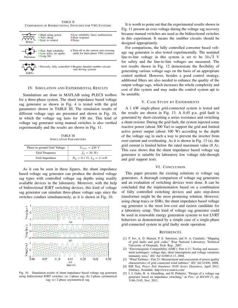
TABLE IICOMPARISON OF BIDIRECTIONAL SWITCHES FOR VSG SYSTEMS
High rating powerVery cheapEasy to control
Low reliability (have malfunction)Slow responseNoisyRelays
Fast, high reliabilityLow noise, no sparksLong life
Turn-off at the current zero-crossing(unfit for three-phase VSG systems)
Thyristors
IGBTs
Precisely, fully controlled Require detailed snubber circuitsand driving systems
IV. SIMULATION AND EXPERIMENTAL RESULTS
Simulations are done in MATLAB using PLECS toolboxfor a three-phase system. The shunt impedance based voltagesag generator as shown in Fig. 4 is tested with the gridparameters shown in TABLE III. The simulation results ofdifferent voltage sags are presented and shown in Fig. 10,in which the voltage sag lasts for 100 ms. This kind ofvoltage sag generator using manual switches is also verifiedexperimentally and the results are shown in Fig. 11.
TABLE IIISIMULATION PARAMETERS
Phase-to-ground Grid Voltage Vrms = 230 V
Grid Frequency fg = 50 Hz
Grid Impedance Rg = 0.1 Ω, Lg = 2 mH
As it can be seen in these figures, the shunt impedancebased voltage sag generator can produce the desired voltagesag types with controlled voltage sag depths using readilyavailable devices in the laboratory. Moreover, with the helpof bidirectional IGBT switching devices, this kind of voltagesag generator can simulate three-phase voltage sags since theswitches conduct simultaneously, as it is shown in Fig. 10.
Fig. 10. Simulation results of shunt impedance based voltage sag generatorusing bidirectional IGBT switches: (a) 1-phase sag; (b) 2-phase symmetrical
sag; (c) 2-phase asymmetrical sag.
It is worth to point out that the experimental results shown inFig. 11 present an over-voltage during the voltage sag recoverybecause manual switches are used as the bidirectional switchesin this experiment. It means the snubber circuits should bedesigned appropriately.
For comparisons, the fully controlled converter based volt-age sag generator is also tested experimentally. The nominalline-to-line voltage in this system is set to be 50
√3 V
for safety and the line-to-line voltages are measured. Thetest results shown in Fig. 12 demonstrate the flexibility ofgenerating various voltage sags on the basis of an appropriatecontrol method. However, besides a good control strategy,additional filters are also needed to enhance the quality of theoutput voltage sags, which increases the whole complexity andcost of this system and may make the control system apt tobe unstable.
V. CASE STUDY BY EXPERIMENTS
A 1 kW single-phase grid-connected system is tested andthe results are shown in Fig. 13. A 0.45 p.u. grid fault isgenerated by short-circuiting a series resistance and switchinga shunt resistor. During the grid fault, the system injected somereactive power (about 300 Var) to support the grid and limitedactive power output (about 100 W) according to the depthof the voltage sag in such a way to prevent the inverter fromover-current and overheating. As it is shown in Fig. 13 (a), thegrid current is limited below the rated maximum value (8 A).This case shows that the shunt impedance based voltage saggenerator is suitable for laboratory low voltage ride-throughand grid support tests.
VI. CONCLUSION
This paper presents the existing solutions to voltage saggenerators. A thorough comparison of voltage sag generatorsand an evaluation of switching devices were done. It can beconcluded that the implementation based on a combinationof fully controlled switching devices and auto step-downtransformer might be the most promising solution. However,using cheap traics or SSRs, the shunt impedance based voltagesag generator is the most low-cost and easiest candidate fora laboratory setup. This kind of voltage sag generator couldbe used in renewable energy generation systems to test LVRTbehaviors as demonstrated by a simple case of a single-phasegrid-connected system in grid faulty mode operation.
REFERENCES
[1] F. Iov, A. D. Hansen, P. E. Sørensen, and N. A. Cutululis, “Mappingof grid faults and grid codes,” Risø National Laboratory, TechnicalUniversity of Denmark, Tech. Rep., 2007.
[2] “Electomegnetic Compatibility (EMC)- Part 4-11: Testing and measure-ment techniques- voltage dips, short interruptions and voltage variationsimmunity tests,” IEC Std 61000-4-11, 2004.
[3] “Wind Turbines - Part 21: Measurement and assessment of power qualitycharacteristics of grid connected wind turbines,” IEC Std 61400, 2008.
[4] EM Test, Power Fail Simulator 503N Series Datasheet, April 2012.[Online]. Available: http://www.emtest.com/
[5] I. J. Gabe, H. A. Grundling, and H. Pinheiro, “Design of a voltage saggenerator based on impedance switching,” in Proc. of IECON’11, pp.3140–3145, Nov. 2011.
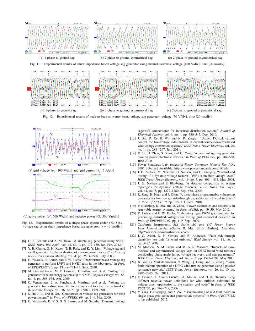
(a) 1-phase to ground sag (b) 2-phase to ground symmetrical sag (c) 2-phase to ground asymmetrical sag
Fig. 11. Experimental results of shunt impedance based voltage sag generator using manual switches: voltage [100 V/div], time [20 ms/div].
(a) 1-phase to ground sag (b) 2-phase to ground symmetrical sag (c) 2-phase to ground asymmetrical sag
Fig. 12. Experimental results of back-to-back converter based voltage sag generator: voltage [50 V/div], time [20 ms/div].
(a) grid voltage [vg : 100 V/div] and grid current [ig : 5 A/div]
(b) active power [P : 500 W/div] and reactive power [Q: 500 Var/div]
Fig. 13. Experimental results of a single-phase system under a 0.45 p.u.voltage sag using shunt impedance based sag generator, [t = 40 ms/div].
[6] O. S. Senturk and A. M. Hava, “A simple sag generator using SSRs,”IEEE Trans. Ind. Appl., vol. 48, no. 1, pp. 172–180, Jan.-Feb. 2012.
[7] Y. H. Chung, G. H. Kwon, T. B. Park, and K. Y. Lim, “Voltage sag andswell generator for the evaluation of custom power devices,” in Proc. ofIEEE-PES General Meeting, vol. 4, pp. 2503–2507, July 2003.
[8] C. Wessels, R. Lohde, and F. W. Fuchs, “Transformer based voltage saggenerator to perform LVRT and HVRT tests in the laboratory,” in Proc.of EPE/PEMC’10, pp. T11–8–T11–13, Sept. 2010.
[9] M. Garcia-Gracia, M. P. Comech, J. Sallan, and et al, “Voltage dipgenerator for wind energy systems up to 5 MV,” Applied Energy, vol. 86,no. 4, pp. 565–574, Apr. 2009.
[10] C. Veganzones, J. A. Sanchez, S. Martinez, and et al, “Voltage dipgenerator for testing wind turbines connected to electrical networks,”Renewable Energy, vol. 36, no. 5, pp. 1588 – 1594, 2011.
[11] S. Hu, J. Li, and H. Xu, “Comparison of voltage sag generators for windpower system,” in Proc. of APPEEC’09, pp. 1–4, Mar. 2009.
[12] C. Venkatesh, D. V. S. S. S. Sarma, and M. Sydulu, “Dynamic voltage
sag/swell compensator for industrial distribution system,” Journal ofElectrical Systems, vol. 6, no. 4, pp. 530–547, Dec. 2010.
[13] J. Dai, D. Xu, B. Wu, and N. R. Zargari, “Unified DC-link currentcontrol for low-voltage ride-through in current-source-converter-basedwind energy conversion systems,” IEEE Trans. Power Electron., vol. 26,no. 1, pp. 288 –297, Jan. 2011.
[14] D. Li, H. Zhou, S. Xiao, and G. Yang, “A new voltage sag generatorbase on power electronic devices,” in Proc. of PEDG’10, pp. 584–588,June 2010.
[15] Power Standards Lab, Industrial Power Corruptor Manual Rev 1.00,2005. [Online]. Available: http://www.powerstandards.com/IPC.php
[16] J. G. Nielsen, M. Newman, H. Nielsen, and F. Blaabjerg, “Control andtesting of a dynamic voltage restorer (DVR) at medium voltage level,”IEEE Trans. Power Electron., vol. 19, no. 3, pp. 806 – 813, May 2004.
[17] J. G. Nielsen and F. Blaabjerg, “A detailed comparison of systemtopologies for dynamic voltage restorers,” IEEE Trans. Ind. Appl.,vol. 41, no. 5, pp. 1272–1280, Sept.-Oct. 2005.
[18] R. Zeng, H. Nian, and P. Zhou, “A three-phase programmable voltage saggenerator for low voltage ride-through capability test of wind turbines,”in Proc. of ECCE’10, pp. 305–311, Sept. 2010.
[19] F. Blaabjerg, K. Ma, and D. Zhou, “Power electronics and reliability inrenewable energy systems,” in Proc. of ISIE, pp. 19–30, May 2012.
[20] R. Lohde and F. W. Fuchs, “Laboratory type PWM grid emulator forgenerating disturbed voltages for testing grid connected devices,” inProc. of EPE/PEMC’09, pp. 1–9, Sept. 2009.
[21] California Instruments, MX Series AC and DC Power SourceUser Manual Series I/Series II, Mar. 2010. [Online]. Available:http://www.californiainstruments.com/
[22] J. C. Ausin, D. N. Gevers, and B. Andresen, “Fault ride-throughcapability test unit for wind turbines,” Wind Energy, vol. 11, no. 1,pp. 3–12, 2008.
[23] M. Mohseni, S. M. Islam, and M. A. S. Masoum, “Impacts of sym-metrical and asymmetrical voltage sags on DFIG-based wind turbinesconsidering phase-angle jump, voltage recovery, and sag parameters,”IEEE Trans. Power Electron., vol. 26, no. 5, pp. 1587–1598, May 2011.
[24] X. Yan, G. Venkataramanan, Y. Wang, Q. Dong, and B. Zhang, “Grid-fault tolerant operation of a DFIG wind turbine generator using a passiveresistance network,” IEEE Trans. Power Electron., vol. 26, no. 10, pp.2896–2905, Oct. 2011.
[25] E. Gomez, J. Alvaro Fuentes, A. Molina, and et al, “Results usingdifferent reactive power definitions for wind turbines submitted tovoltage dips: Application to the spanish grid code,” in Proc. of IEEEPSCE’06, pp. 768–775, 2006.
[26] Y. Yang, F. Blaabjerg, and Z. Zou, “Benchmarking of grid fault modes insingle-phase grid-connected photovoltaic systems,” in Proc. of ECCE’12,to be published, 2012.