Embed Size (px)
Citation preview
Aalborg Universitet
Comparison of Post Weld Treatment of High Strength Steel Welded Joints in MediumCycle FatiguePedersen, Mikkel Melters; Mouritsen, Ole Østergaard; Hansen, Michael Rygaard; Andersen,Jes G.; Wenderby, JimmiPublished in:Welding in the World - Soudage dans le Monde
DOI (link to publication from Publisher):10.1007/BF03263506
Publication date:2010
Document VersionEarly version, also known as pre-print
Link to publication from Aalborg University
Citation for published version (APA):Pedersen, M. M., Mouritsen, O. Ø., Hansen, M. R., Andersen, J. G., & Wenderby, J. (2010). Comparison of PostWeld Treatment of High Strength Steel Welded Joints in Medium Cycle Fatigue. Welding in the World - Soudagedans le Monde, 54(7/8), 208. DOI: 10.1007/BF03263506
General rightsCopyright and moral rights for the publications made accessible in the public portal are retained by the authors and/or other copyright ownersand it is a condition of accessing publications that users recognise and abide by the legal requirements associated with these rights.
? Users may download and print one copy of any publication from the public portal for the purpose of private study or research. ? You may not further distribute the material or use it for any profit-making activity or commercial gain ? You may freely distribute the URL identifying the publication in the public portal ?
Take down policyIf you believe that this document breaches copyright please contact us at [email protected] providing details, and we will remove access tothe work immediately and investigate your claim.
Downloaded from vbn.aau.dk on: september 01, 2018
1/13
Danish delegation
XIII-2272-09
Comparison of Post Weld Treatment of High Strength Steel Welded Joints in Medium Cycle Fatigue
M.M. Pedersen1,3, O.Ø. Mouritsen1, M.R. Hansen2, J.G. Andersen3, J. Wenderby3
1 Aalborg University, Dept. of Mechanical Engineering, DK-9220, Denmark. 2 University of Agder, Dept. of Engineering, NO-4876, Norway.
3 HMF A/S, DK-8270, Denmark. Contact: [email protected]
Abstract. This paper presents a comparison of three post weld treatments for fatigue life improvement of welded joints. The objective is to determine the most suitable post weld treatment for implementation in mass production of certain crane components manufactured from very high strength steel. The processes investigated are; burr grinding, TIG dressing and ultrasonic impact treatment. The focus of this investigation is on the so-called medium cycle area, i.e. 10,000-500,000 cycles and very high stress ranges. In this area of fatigue design, the use of very high strength steel becomes necessary, since the stress range can exceed the yield strength of ordinary structural steel, especially when considering positive stress ratios (R>0). Fatigue experiments and qualitative evaluation of the different post weld treatments leads to the selection of TIG dressing. The process of implementing TIG dressing in mass production and some inherent initial problems are discussed. The treatment of a few critical welds leads to a significant increase in fatigue performance of the entire structure and the possibility for better utilization of very high strength steel. Keywords: experimental investigation, high strength steel, medium cycle fatigue, post-weld treatment, fatigue testing, practical implementation, mass production.
1. Introduction It is a well known fact that welded joints have a low fatigue strength compared to the base material. This is mainly caused by local stress concentrations due to the presence of notches and high tensile residual stresses. Notches occur both because of the geometry of the joint, but also because of weld imperfections such as undercuts and slag inclusions. Tensile residual stresses arise from the contraction of the weld metal during cooling and solidification. The fatigue strength of as-welded joints proves to be practically independent of the base material strength. Thus, when applying higher strength steels, the gap between the static and fatigue strength increases. However, in many applications, e.g. mobile machinery, there is a tendency to pursue an increase in the performance to weight ratio by applying higher strength steels. In such cases, the fatigue strength of the welded joints becomes the dominating factor and limits the benefit of the application of the high strength steel. Improvement of the fatigue strength of welded joints by application of different post-weld treatments has therefore received much attention lately e.g. [1-5], especially treatments based on high frequency peening, e.g. UIT. These relatively new treatments consistently provide very significant improvements in fatigue strength, particularly in the high cycle regime.
2/13
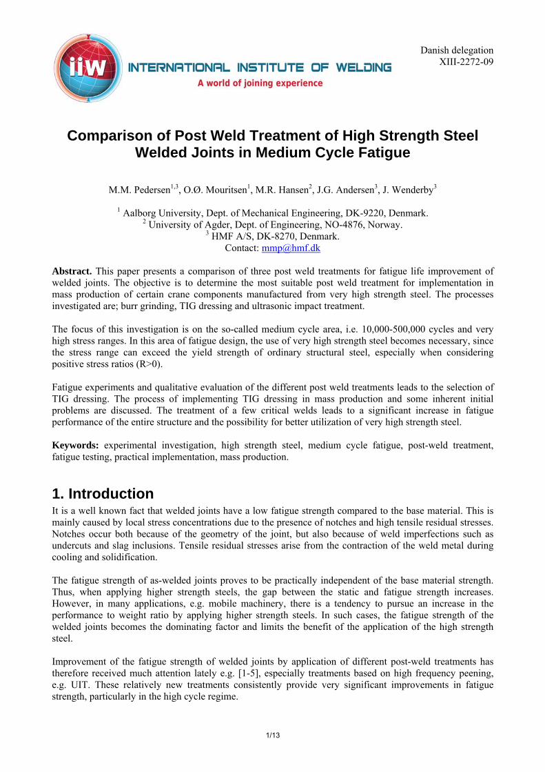
Unfortunately, only little effort has been put into investigation of the medium cycle area, i.e. the upper area marked in Fig. 1. In this area of fatigue design, there is an obvious reason for using high strength steels, since the stress range exceeds the yield strength of ordinary structural steel, assuming R≥0. Ordinarily this area would be classified as low cycle fatigue, and plasticity should be taken into account. When applying high strength steel, on the other hand, the elastic region extends upwards in the Wöhler diagram, and plasticity is not an issue. Even though the fatigue strength of as-welded joints is independent of the base material strength at lower stress ranges, this is not the case for the high stress / medium cycle area. There is a need for special fatigue design guidelines in this area considering the use of high strength steel. An example is the IIW parent material curve FAT160, see Hobbacher [6], which is too conservative for high strength steel. The new crane code EN13001 [7] for instance suggests FAT315 for high strength steel parent material.
Fig. 1: Net of S-N curves according to the IIW [6].
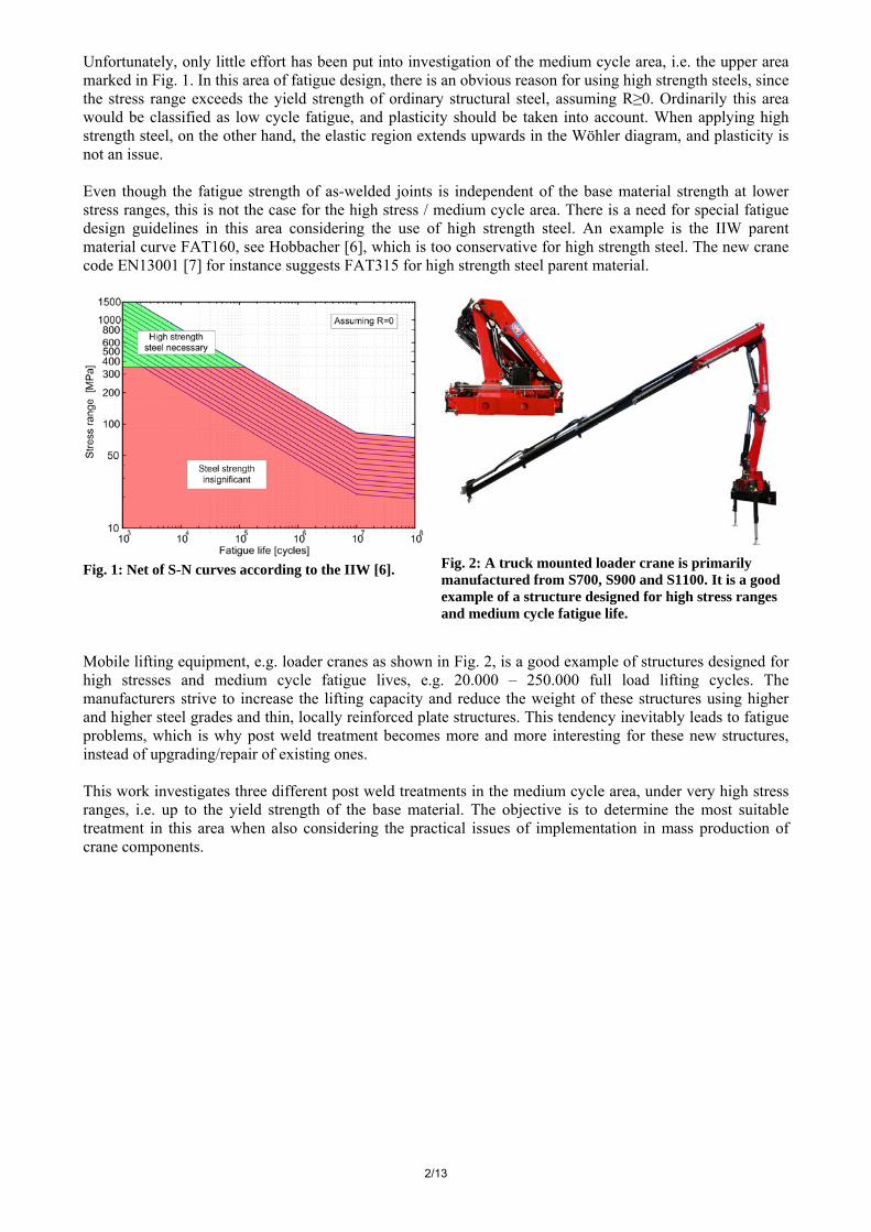
Fig. 2: A truck mounted loader crane is primarily manufactured from S700, S900 and S1100. It is a good example of a structure designed for high stress ranges and medium cycle fatigue life.
Mobile lifting equipment, e.g. loader cranes as shown in Fig. 2, is a good example of structures designed for high stresses and medium cycle fatigue lives, e.g. 20.000 – 250.000 full load lifting cycles. The manufacturers strive to increase the lifting capacity and reduce the weight of these structures using higher and higher steel grades and thin, locally reinforced plate structures. This tendency inevitably leads to fatigue problems, which is why post weld treatment becomes more and more interesting for these new structures, instead of upgrading/repair of existing ones. This work investigates three different post weld treatments in the medium cycle area, under very high stress ranges, i.e. up to the yield strength of the base material. The objective is to determine the most suitable treatment in this area when also considering the practical issues of implementation in mass production of crane components.
3/13
2. Experimental 2.1. General The fatigue investigation was carried out on simple T-joint specimens in four point bending. The high stress ranges and the required accuracy are more easily achieved in bending tests as compared to tests in tension. Furthermore, by testing in bending loading, misalignment-induced secondary bending stresses are avoided. This is essential, since the different post weld treatments cause different levels of distortion in the specimens.
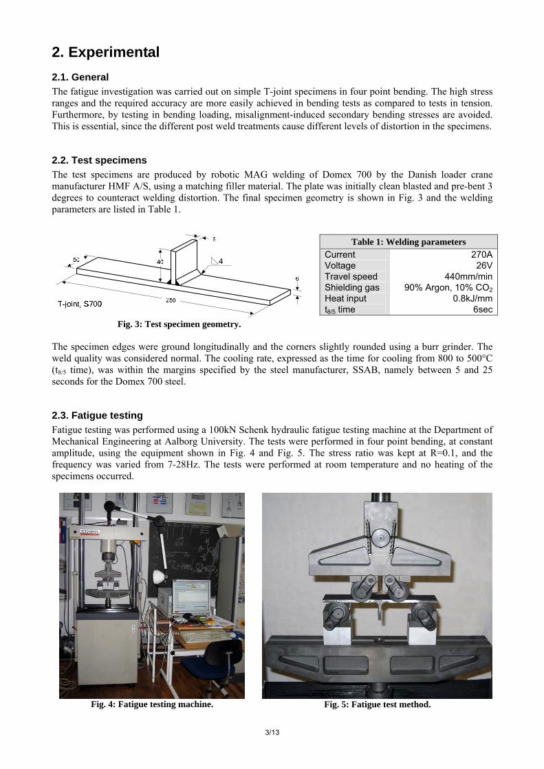
2.2. Test specimens The test specimens are produced by robotic MAG welding of Domex 700 by the Danish loader crane manufacturer HMF A/S, using a matching filler material. The plate was initially clean blasted and pre-bent 3 degrees to counteract welding distortion. The final specimen geometry is shown in Fig. 3 and the welding parameters are listed in Table 1.
Fig. 3: Test specimen geometry.
The specimen edges were ground longitudinally and the corners slightly rounded using a burr grinder. The weld quality was considered normal. The cooling rate, expressed as the time for cooling from 800 to 500°C (t8/5 time), was within the margins specified by the steel manufacturer, SSAB, namely between 5 and 25 seconds for the Domex 700 steel.
2.3. Fatigue testing Fatigue testing was performed using a 100kN Schenk hydraulic fatigue testing machine at the Department of Mechanical Engineering at Aalborg University. The tests were performed in four point bending, at constant amplitude, using the equipment shown in Fig. 4 and Fig. 5. The stress ratio was kept at R=0.1, and the frequency was varied from 7-28Hz. The tests were performed at room temperature and no heating of the specimens occurred.
Fig. 4: Fatigue testing machine.
Fig. 5: Fatigue test method.
Table 1: Welding parameters Current 270AVoltage 26VTravel speed 440mm/minShielding gas 90% Argon, 10% CO2Heat input 0.8kJ/mmt8/5 time 6sec
4/13
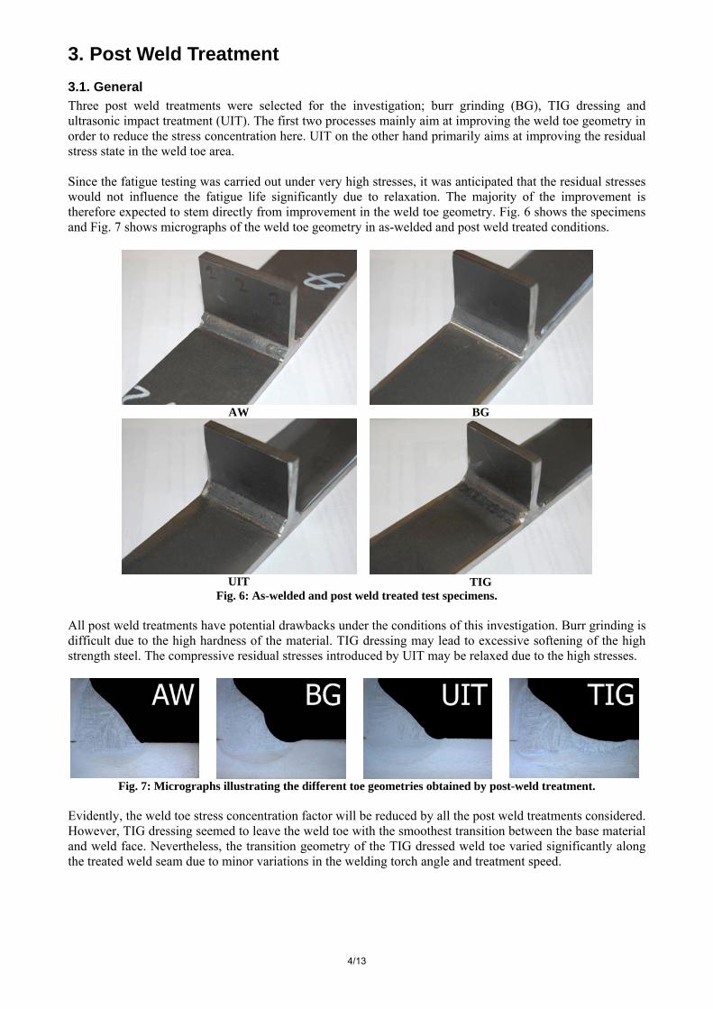
3. Post Weld Treatment 3.1. General Three post weld treatments were selected for the investigation; burr grinding (BG), TIG dressing and ultrasonic impact treatment (UIT). The first two processes mainly aim at improving the weld toe geometry in order to reduce the stress concentration here. UIT on the other hand primarily aims at improving the residual stress state in the weld toe area. Since the fatigue testing was carried out under very high stresses, it was anticipated that the residual stresses would not influence the fatigue life significantly due to relaxation. The majority of the improvement is therefore expected to stem directly from improvement in the weld toe geometry. Fig. 6 shows the specimens and Fig. 7 shows micrographs of the weld toe geometry in as-welded and post weld treated conditions.
AW
BG
UIT
TIG
Fig. 6: As-welded and post weld treated test specimens. All post weld treatments have potential drawbacks under the conditions of this investigation. Burr grinding is difficult due to the high hardness of the material. TIG dressing may lead to excessive softening of the high strength steel. The compressive residual stresses introduced by UIT may be relaxed due to the high stresses.
Fig. 7: Micrographs illustrating the different toe geometries obtained by post-weld treatment.
Evidently, the weld toe stress concentration factor will be reduced by all the post weld treatments considered. However, TIG dressing seemed to leave the weld toe with the smoothest transition between the base material and weld face. Nevertheless, the transition geometry of the TIG dressed weld toe varied significantly along the treated weld seam due to minor variations in the welding torch angle and treatment speed.
5/13
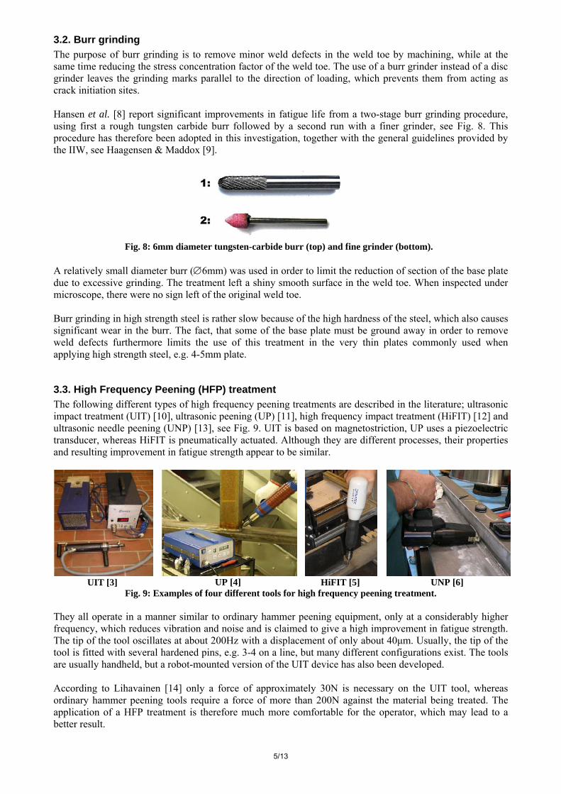
3.2. Burr grinding The purpose of burr grinding is to remove minor weld defects in the weld toe by machining, while at the same time reducing the stress concentration factor of the weld toe. The use of a burr grinder instead of a disc grinder leaves the grinding marks parallel to the direction of loading, which prevents them from acting as crack initiation sites. Hansen et al. [8] report significant improvements in fatigue life from a two-stage burr grinding procedure, using first a rough tungsten carbide burr followed by a second run with a finer grinder, see Fig. 8. This procedure has therefore been adopted in this investigation, together with the general guidelines provided by the IIW, see Haagensen & Maddox [9].
Fig. 8: 6mm diameter tungsten-carbide burr (top) and fine grinder (bottom).
A relatively small diameter burr (∅6mm) was used in order to limit the reduction of section of the base plate due to excessive grinding. The treatment left a shiny smooth surface in the weld toe. When inspected under microscope, there were no sign left of the original weld toe. Burr grinding in high strength steel is rather slow because of the high hardness of the steel, which also causes significant wear in the burr. The fact, that some of the base plate must be ground away in order to remove weld defects furthermore limits the use of this treatment in the very thin plates commonly used when applying high strength steel, e.g. 4-5mm plate.
3.3. High Frequency Peening (HFP) treatment The following different types of high frequency peening treatments are described in the literature; ultrasonic impact treatment (UIT) [10], ultrasonic peening (UP) [11], high frequency impact treatment (HiFIT) [12] and ultrasonic needle peening (UNP) [13], see Fig. 9. UIT is based on magnetostriction, UP uses a piezoelectric transducer, whereas HiFIT is pneumatically actuated. Although they are different processes, their properties and resulting improvement in fatigue strength appear to be similar.
UIT [3] UP [4] HiFIT [5] UNP [6]
Fig. 9: Examples of four different tools for high frequency peening treatment. They all operate in a manner similar to ordinary hammer peening equipment, only at a considerably higher frequency, which reduces vibration and noise and is claimed to give a high improvement in fatigue strength. The tip of the tool oscillates at about 200Hz with a displacement of only about 40μm. Usually, the tip of the tool is fitted with several hardened pins, e.g. 3-4 on a line, but many different configurations exist. The tools are usually handheld, but a robot-mounted version of the UIT device has also been developed. According to Lihavainen [14] only a force of approximately 30N is necessary on the UIT tool, whereas ordinary hammer peening tools require a force of more than 200N against the material being treated. The application of a HFP treatment is therefore much more comfortable for the operator, which may lead to a better result.
6/13
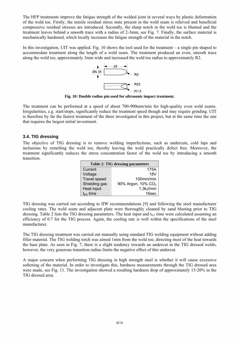
The HFP treatments improve the fatigue strength of the welded joint in several ways by plastic deformation of the weld toe. Firstly, the tensile residual stress state present in the weld seam is relieved and beneficial compressive residual stresses are introduced. Secondly, the sharp notch in the weld toe is blunted and the treatment leaves behind a smooth trace with a radius of 2-3mm, see Fig. 7. Finally, the surface material is mechanically hardened, which locally increases the fatigue strength of the material in the notch. In this investigation, UIT was applied. Fig. 10 shows the tool used for the treatment – a single pin shaped to accommodate treatment along the length of a weld seam. The treatment produced an even, smooth trace along the weld toe, approximately 3mm wide and increased the weld toe radius to approximately R2.
Fig. 10: Double radius pin used for ultrasonic impact treatment.
The treatment can be performed at a speed of about 700-900mm/min for high-quality even weld seams. Irregularities, e.g. start/stops, significantly reduce the treatment speed though and may require grinding. UIT is therefore by far the fastest treatment of the three investigated in this project, but at the same time the one that requires the largest initial investment.
3.4. TIG dressing The objective of TIG dressing is to remove welding imperfections, such as undercuts, cold laps and inclusions by remelting the weld toe, thereby leaving the weld practically defect free. Moreover, the treatment significantly reduces the stress concentration factor of the weld toe by introducing a smooth transition.
Table 2: TIG dressing parameters Current 175AVoltage 18VTravel speed 100mm/minShielding gas 90% Argon, 10% CO2Heat input 1.3kJ/mmt8/5 time 16sec
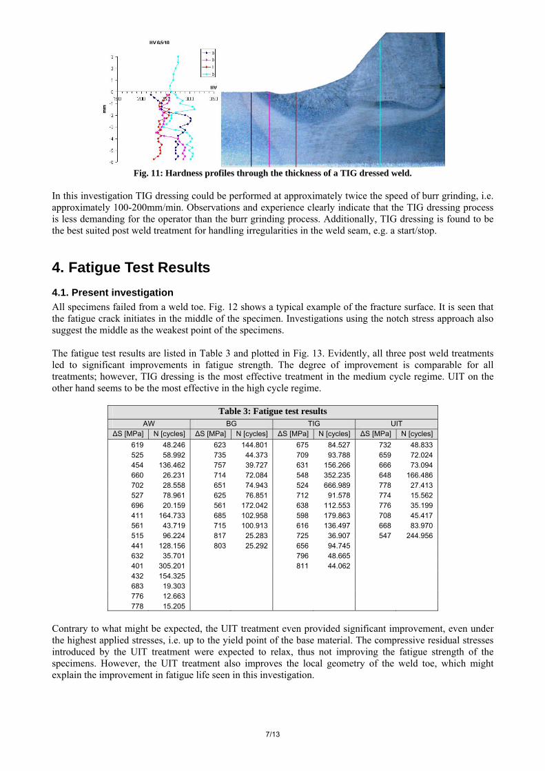
TIG dressing was carried out according to IIW recommendations [9] and following the steel manufacturer cooling rates. The weld seam and adjacent plate were thoroughly cleaned by sand blasting prior to TIG dressing. Table 2 lists the TIG dressing parameters. The heat input and t8/5 time were calculated assuming an efficiency of 0.7 for the TIG process. Again, the cooling rate is well within the specifications of the steel manufacturer. The TIG dressing treatment was carried out manually using standard TIG welding equipment without adding filler material. The TIG welding torch was aimed 1mm from the weld toe, directing most of the heat towards the base plate. As seen in Fig. 7, there is a slight tendency towards an undercut in the TIG dressed welds; however, the very generous transition radius limits the negative effect of this undercut. A major concern when performing TIG dressing in high strength steel is whether it will cause excessive softening of the material. In order to investigate this, hardness measurements through the TIG dressed area were made, see Fig. 11. The investigation showed a resulting hardness drop of approximately 15-20% in the TIG dressed area.
7/13
Fig. 11: Hardness profiles through the thickness of a TIG dressed weld.
In this investigation TIG dressing could be performed at approximately twice the speed of burr grinding, i.e. approximately 100-200mm/min. Observations and experience clearly indicate that the TIG dressing process is less demanding for the operator than the burr grinding process. Additionally, TIG dressing is found to be the best suited post weld treatment for handling irregularities in the weld seam, e.g. a start/stop.
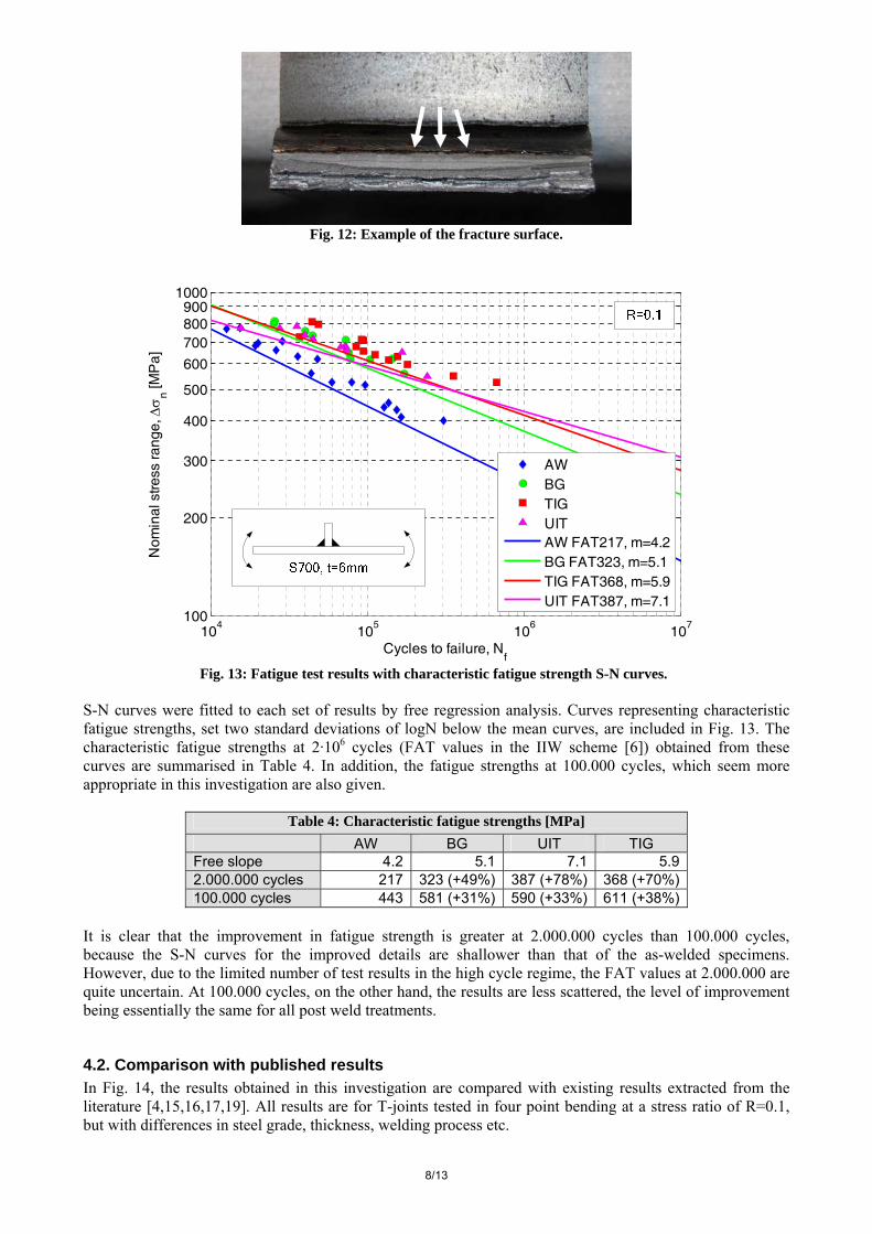
4. Fatigue Test Results 4.1. Present investigation All specimens failed from a weld toe. Fig. 12 shows a typical example of the fracture surface. It is seen that the fatigue crack initiates in the middle of the specimen. Investigations using the notch stress approach also suggest the middle as the weakest point of the specimens. The fatigue test results are listed in Table 3 and plotted in Fig. 13. Evidently, all three post weld treatments led to significant improvements in fatigue strength. The degree of improvement is comparable for all treatments; however, TIG dressing is the most effective treatment in the medium cycle regime. UIT on the other hand seems to be the most effective in the high cycle regime.
Table 3: Fatigue test results AW BG TIG UIT
ΔS [MPa] N [cycles] ΔS [MPa] N [cycles] ΔS [MPa] N [cycles] ΔS [MPa] N [cycles] 619 48.246 623 144.801 675 84.527 732 48.833 525 58.992 735 44.373 709 93.788 659 72.024 454 136.462 757 39.727 631 156.266 666 73.094 660 26.231 714 72.084 548 352.235 648 166.486 702 28.558 651 74.943 524 666.989 778 27.413 527 78.961 625 76.851 712 91.578 774 15.562 696 20.159 561 172.042 638 112.553 776 35.199 411 164.733 685 102.958 598 179.863 708 45.417 561 43.719 715 100.913 616 136.497 668 83.970 515 96.224 817 25.283 725 36.907 547 244.956 441 128.156 803 25.292 656 94.745 632 35.701 796 48.665 401 305.201 811 44.062 432 154.325 683 19.303 776 12.663 778 15.205
Contrary to what might be expected, the UIT treatment even provided significant improvement, even under the highest applied stresses, i.e. up to the yield point of the base material. The compressive residual stresses introduced by the UIT treatment were expected to relax, thus not improving the fatigue strength of the specimens. However, the UIT treatment also improves the local geometry of the weld toe, which might explain the improvement in fatigue life seen in this investigation.
8/13
Fig. 12: Example of the fracture surface.
104
105
106
107
100
200
300
400
500
600
700800900
1000
Cycles to failure, Nf
Nom
inal
stre
ss ra
nge,
Δσ
n [M
Pa]
AWBGTIGUITAW FAT217, m=4.2BG FAT323, m=5.1TIG FAT368, m=5.9UIT FAT387, m=7.1
Fig. 13: Fatigue test results with characteristic fatigue strength S-N curves.
S-N curves were fitted to each set of results by free regression analysis. Curves representing characteristic fatigue strengths, set two standard deviations of logN below the mean curves, are included in Fig. 13. The characteristic fatigue strengths at 2·106 cycles (FAT values in the IIW scheme [6]) obtained from these curves are summarised in Table 4. In addition, the fatigue strengths at 100.000 cycles, which seem more appropriate in this investigation are also given.
Table 4: Characteristic fatigue strengths [MPa] AW BG UIT TIG Free slope 4.2 5.1 7.1 5.9 2.000.000 cycles 217 323 (+49%) 387 (+78%) 368 (+70%) 100.000 cycles 443 581 (+31%) 590 (+33%) 611 (+38%)
It is clear that the improvement in fatigue strength is greater at 2.000.000 cycles than 100.000 cycles, because the S-N curves for the improved details are shallower than that of the as-welded specimens. However, due to the limited number of test results in the high cycle regime, the FAT values at 2.000.000 are quite uncertain. At 100.000 cycles, on the other hand, the results are less scattered, the level of improvement being essentially the same for all post weld treatments.
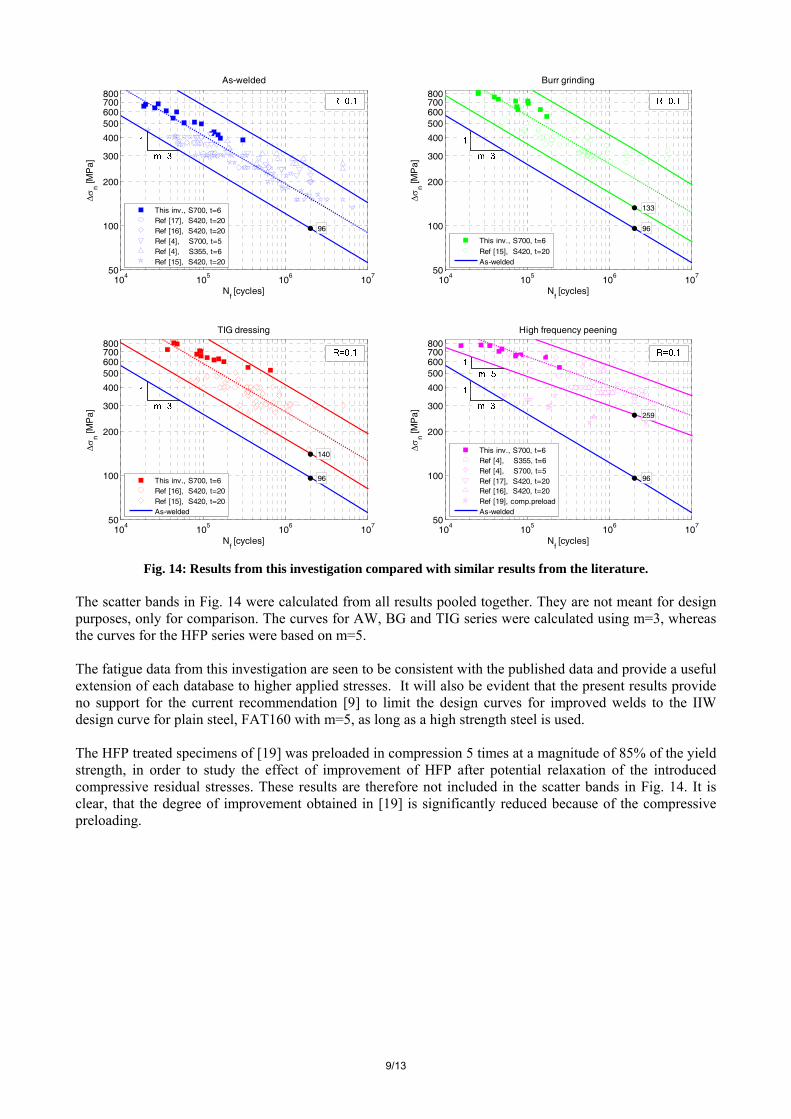
4.2. Comparison with published results In Fig. 14, the results obtained in this investigation are compared with existing results extracted from the literature [4,15,16,17,19]. All results are for T-joints tested in four point bending at a stress ratio of R=0.1, but with differences in steel grade, thickness, welding process etc.
9/13
104
105
106
107
50
100
200
300
400
500600700800
96
Nf [cycles]
Δσ
n [M
Pa]
As-welded
This inv., S700, t=6Ref [17], S420, t=20Ref [16], S420, t=20Ref [4], S700, t=5Ref [4], S355, t=6Ref [15], S420, t=20
104
105
106
107
50
100
200
300
400
500600700800
96
133
Nf [cycles]
Δσ
n [M
Pa]
Burr grinding
This inv., S700, t=6
Ref [15], S420, t=20As-welded
104
105
106
107
50
100
200
300
400
500600700800
96
140
Nf [cycles]
Δσ
n [M
Pa]
TIG dressing
This inv., S700, t=6Ref [16], S420, t=20Ref [15], S420, t=20As-welded
104
105
106
107
50
100
200
300
400
500600700800
96
259
Nf [cycles]
Δσ
n [M
Pa]
High frequency peening
This inv., S700, t=6Ref [4], S355, t=6Ref [4], S700, t=5Ref [17], S420, t=20Ref [16], S420, t=20Ref [19], comp.preloadAs-welded
Fig. 14: Results from this investigation compared with similar results from the literature.
The scatter bands in Fig. 14 were calculated from all results pooled together. They are not meant for design purposes, only for comparison. The curves for AW, BG and TIG series were calculated using m=3, whereas the curves for the HFP series were based on m=5. The fatigue data from this investigation are seen to be consistent with the published data and provide a useful extension of each database to higher applied stresses. It will also be evident that the present results provide no support for the current recommendation [9] to limit the design curves for improved welds to the IIW design curve for plain steel, FAT160 with m=5, as long as a high strength steel is used. The HFP treated specimens of [19] was preloaded in compression 5 times at a magnitude of 85% of the yield strength, in order to study the effect of improvement of HFP after potential relaxation of the introduced compressive residual stresses. These results are therefore not included in the scatter bands in Fig. 14. It is clear, that the degree of improvement obtained in [19] is significantly reduced because of the compressive preloading.
10/13
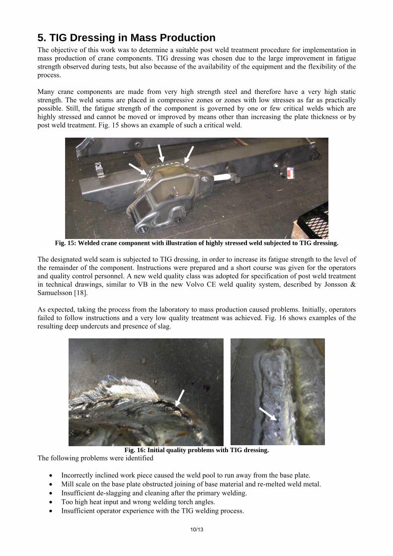
5. TIG Dressing in Mass Production The objective of this work was to determine a suitable post weld treatment procedure for implementation in mass production of crane components. TIG dressing was chosen due to the large improvement in fatigue strength observed during tests, but also because of the availability of the equipment and the flexibility of the process. Many crane components are made from very high strength steel and therefore have a very high static strength. The weld seams are placed in compressive zones or zones with low stresses as far as practically possible. Still, the fatigue strength of the component is governed by one or few critical welds which are highly stressed and cannot be moved or improved by means other than increasing the plate thickness or by post weld treatment. Fig. 15 shows an example of such a critical weld.
Fig. 15: Welded crane component with illustration of highly stressed weld subjected to TIG dressing.
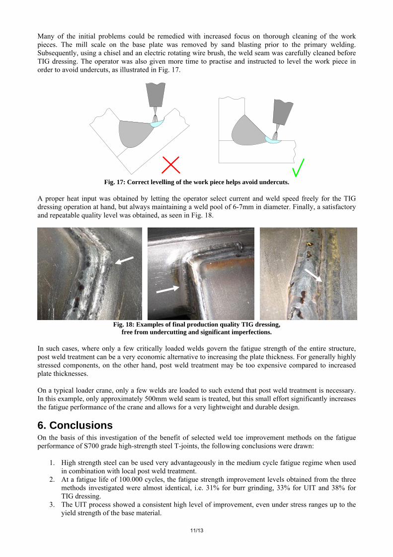
The designated weld seam is subjected to TIG dressing, in order to increase its fatigue strength to the level of the remainder of the component. Instructions were prepared and a short course was given for the operators and quality control personnel. A new weld quality class was adopted for specification of post weld treatment in technical drawings, similar to VB in the new Volvo CE weld quality system, described by Jonsson & Samuelsson [18]. As expected, taking the process from the laboratory to mass production caused problems. Initially, operators failed to follow instructions and a very low quality treatment was achieved. Fig. 16 shows examples of the resulting deep undercuts and presence of slag.
Fig. 16: Initial quality problems with TIG dressing.
The following problems were identified
• Incorrectly inclined work piece caused the weld pool to run away from the base plate. • Mill scale on the base plate obstructed joining of base material and re-melted weld metal. • Insufficient de-slagging and cleaning after the primary welding. • Too high heat input and wrong welding torch angles. • Insufficient operator experience with the TIG welding process.
11/13
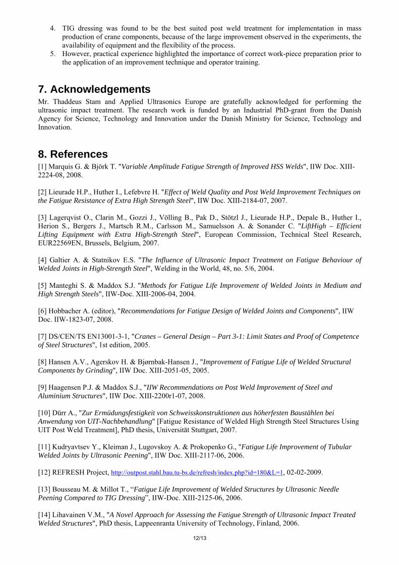
Many of the initial problems could be remedied with increased focus on thorough cleaning of the work pieces. The mill scale on the base plate was removed by sand blasting prior to the primary welding. Subsequently, using a chisel and an electric rotating wire brush, the weld seam was carefully cleaned before TIG dressing. The operator was also given more time to practise and instructed to level the work piece in order to avoid undercuts, as illustrated in Fig. 17.
Fig. 17: Correct levelling of the work piece helps avoid undercuts.
A proper heat input was obtained by letting the operator select current and weld speed freely for the TIG dressing operation at hand, but always maintaining a weld pool of 6-7mm in diameter. Finally, a satisfactory and repeatable quality level was obtained, as seen in Fig. 18.
Fig. 18: Examples of final production quality TIG dressing,
free from undercutting and significant imperfections. In such cases, where only a few critically loaded welds govern the fatigue strength of the entire structure, post weld treatment can be a very economic alternative to increasing the plate thickness. For generally highly stressed components, on the other hand, post weld treatment may be too expensive compared to increased plate thicknesses. On a typical loader crane, only a few welds are loaded to such extend that post weld treatment is necessary. In this example, only approximately 500mm weld seam is treated, but this small effort significantly increases the fatigue performance of the crane and allows for a very lightweight and durable design.
6. Conclusions On the basis of this investigation of the benefit of selected weld toe improvement methods on the fatigue performance of S700 grade high-strength steel T-joints, the following conclusions were drawn:
1. High strength steel can be used very advantageously in the medium cycle fatigue regime when used in combination with local post weld treatment.
2. At a fatigue life of 100.000 cycles, the fatigue strength improvement levels obtained from the three methods investigated were almost identical, i.e. 31% for burr grinding, 33% for UIT and 38% for TIG dressing.
3. The UIT process showed a consistent high level of improvement, even under stress ranges up to the yield strength of the base material.
12/13
4. TIG dressing was found to be the best suited post weld treatment for implementation in mass production of crane components, because of the large improvement observed in the experiments, the availability of equipment and the flexibility of the process.
5. However, practical experience highlighted the importance of correct work-piece preparation prior to the application of an improvement technique and operator training.
7. Acknowledgements Mr. Thaddeus Stam and Applied Ultrasonics Europe are gratefully acknowledged for performing the ultrasonic impact treatment. The research work is funded by an Industrial PhD-grant from the Danish Agency for Science, Technology and Innovation under the Danish Ministry for Science, Technology and Innovation.
8. References [1] Marquis G. & Björk T. "Variable Amplitude Fatigue Strength of Improved HSS Welds", IIW Doc. XIII-2224-08, 2008. [2] Lieurade H.P., Huther I., Lefebvre H. "Effect of Weld Quality and Post Weld Improvement Techniques on the Fatigue Resistance of Extra High Strength Steel", IIW Doc. XIII-2184-07, 2007. [3] Lagerqvist O., Clarin M., Gozzi J., Völling B., Pak D., Stötzl J., Lieurade H.P., Depale B., Huther I., Herion S., Bergers J., Martsch R.M., Carlsson M., Samuelsson A. & Sonander C. "LiftHigh – Efficient Lifting Equipment with Extra High-Strength Steel", European Commission, Technical Steel Research, EUR22569EN, Brussels, Belgium, 2007. [4] Galtier A. & Statnikov E.S. "The Influence of Ultrasonic Impact Treatment on Fatigue Behaviour of Welded Joints in High-Strength Steel", Welding in the World, 48, no. 5/6, 2004. [5] Manteghi S. & Maddox S.J. "Methods for Fatigue Life Improvement of Welded Joints in Medium and High Strength Steels", IIW-Doc. XIII-2006-04, 2004. [6] Hobbacher A. (editor), "Recommendations for Fatigue Design of Welded Joints and Components", IIW Doc. IIW-1823-07, 2008. [7] DS/CEN/TS EN13001-3-1, "Cranes – General Design – Part 3-1: Limit States and Proof of Competence of Steel Structures", 1st edition, 2005. [8] Hansen A.V., Agerskov H. & Bjørnbak-Hansen J., "Improvement of Fatigue Life of Welded Structural Components by Grinding", IIW Doc. XIII-2051-05, 2005. [9] Haagensen P.J. & Maddox S.J., "IIW Recommendations on Post Weld Improvement of Steel and Aluminium Structures", IIW Doc. XIII-2200r1-07, 2008. [10] Dürr A., "Zur Ermüdungsfestigkeit von Schweisskonstruktionen aus höherfesten Baustählen bei Anwendung von UIT-Nachbehandlung" [Fatigue Resistance of Welded High Strength Steel Structures Using UIT Post Weld Treatment], PhD thesis, Universität Stuttgart, 2007. [11] Kudryavtsev Y., Kleiman J., Lugovskoy A. & Prokopenko G., "Fatigue Life Improvement of Tubular Welded Joints by Ultrasonic Peening", IIW Doc. XIII-2117-06, 2006. [12] REFRESH Project, http://outpost.stahl.bau.tu-bs.de/refresh/index.php?id=180&L=1, 02-02-2009. [13] Bousseau M. & Millot T., “Fatigue Life Improvement of Welded Structures by Ultrasonic Needle Peening Compared to TIG Dressing”, IIW-Doc. XIII-2125-06, 2006. [14] Lihavainen V.M., "A Novel Approach for Assessing the Fatigue Strength of Ultrasonic Impact Treated Welded Structures", PhD thesis, Lappeenranta University of Technology, Finland, 2006.

13/13
[15] Haagensen P.J. "IIW’s Round Robin and Design Recommendations for Improvement Methods", Proceedings of the IIW 50th Annual Assembly Conference, San Francisco, Welding Research Council Inc., New York, USA, 1997. [16] Statnikov E.S., Muktepavel V.O. & Blomqvist A. "Comparison of Ultrasonic Impact Treatment (UIT) and Other Fatigue Life Improvement Methods", Welding in the World 46, pp. 28- 39, 2002. [17] Trufiakov V.I., Statnikov E.S., Mikheev P.P. & Kuzmenko A.Z. "The Efficiency of Ultrasonic Impact Treatment for Improving the Fatigue Strength", IIW Doc. XIII-1745-98, 1998. [18] Jonsson B. & Samuelsson J., "A New Weld Quality System", IIW Doc. XIII-2235-08, 2008. [19] Lopez-Martinez L. & Haagensen P.J. "Life Extenion of Class F and Class F2 Details Using Ultrasonic Peening", IIW Doc. XIII-2143-07, 2007.