Embed Size (px)
Citation preview

1
OVERVIEW OF THE MISSION DESIGN REFERENCE TRAJECTORY FOR NASA’S ASTEROID
REDIRECT ROBOTIC MISSION
Melissa L. McGuire,* Nathan J. Strange,† Laura M. Burke,‡ Steven L. McCarty,§ Gregory B. Lantoine,** Min Qu,†† Haijun Shen,‡‡
David A. Smith,§§ and Matthew A. Vavrina***
The National Aeronautics and Space Administration’s (NASA’s) recently can-celled Asteroid Redirect Mission was proposed to rendezvous with and character-ize a 100 m plus class near-Earth asteroid and provide the capability to capture and retrieve a boulder off of the surface of the asteroid and bring the asteroidal materi-al back to cislunar space.1 Leveraging the best of NASA’s science, technology, and human exploration efforts, this mission was originally conceived to support observation campaigns, advanced solar electric propulsion, and NASA’s Space Launch System heavy-lift rocket and Orion crew vehicle. The asteroid characteri-zation and capture portion of ARM was referred to as the Asteroid Redirect Ro-botic Mission (ARRM) and was focused on the robotic capture and then redirec-tion of an asteroidal boulder mass from the reference target, asteroid 2008 EV5, in-to an orbit near the Moon, referred to as a Near Rectilinear Halo Orbit where as-tronauts would visit and study it. The purpose of this paper is to document the fi-nal reference trajectory of ARRM and the challenges and unique methods em-ployed in the trajectory design of the mission.
*Lead Mission Design Engineer, ARRM Mission Design Deputy, Mission Architecture and Analysis Branch, NASA Glenn Research Center, 21000 Brookpark Road, Cleveland, Ohio 44135. [email protected]. †ARRM Mission Design Manager, Mission Design and Navigation Section, Jet Propulsion Laboratory, 4800 Oak Grove Dr. Pasadena, California 91109. [email protected]. ‡Aerospace Engineer, Mission Architecture and Analysis Branch, NASA Glenn Research Center, 21000 Brookpark Road, Cleveland, Ohio 44135. [email protected]. §Aerospace Engineer, Mission Architecture and Analysis Branch, NASA Glenn Research Center, 21000 Brookpark Road, Cleveland, Ohio 44135. [email protected]. **Mission Design Engineer, Mission Design and Navigation Section, Jet Propulsion Laboratory, 4800 Oak Grove Dr. Pasadena, California 91109, [email protected]. ††Staff Scientist, Analytical Mechanics Associates, Inc., 21 Enterprise Parkway, Suite 300, Hampton, Virginia 23666. [email protected]. ‡‡Supervising Engineer, Analytical Mechanics Associates, Inc., 21 Enterprise Parkway, Suite 300, Hampton, Virginia 23666. [email protected]. §§Aerospace Engineer, Mission Architecture and Analysis Branch (LSM), NASA Glenn Research Center, 21000 Brookpark Road, Cleveland, Ohio 44135, [email protected]. ***Senior Systems Engineer, a.i. solutions, 4500 Forbes Boulevard Suite 300, Lanham, Maryland 20706. [email protected].
AAS 17-585
https://ntrs.nasa.gov/search.jsp?R=20170010282 2019-06-12T09:00:44+00:00Z

2
INTRODUCTION
The National Aeronautics and Space Administration’s (NASA’s) proposed Asteroid Redirect Mission concept would robotically capture and then redirect an asteroidal boulder mass into a stable lunar orbit where astronauts would visit and study it. After the initial crew visit, this aster-oidal mass would be moved into a long term stable Lunar orbit where it would remain in place for over 100 years, allowing potential follow-up visits.
This document captures an example reference trajectory for the Asteroid Redirection Robotic Mission (ARRM). It provides a consistent set of data from mission design to be used in the de-sign of the Asteroid Redirect Vehicle (ARV) capable of flying the trajectory described. However, this is not the final ARRM trajectory design and it does not fully encompass the performance en-velope required if a different target asteroid is chosen. This document contains a description of this reference trajectory and the associated ground rules and assumptions.
TRAJECTORY MODELING ASSUMPTIONS
The trajectory modeling for the round trip asteroid mission assumed the use of a high power, mass efficient 40 kW Solar Electric Propulsion (SEP) system. Assumptions of thruster string per-formance and power available to the SEP system were inputs given to the mission design team from the ARRM spacecraft subsystem teams. All of the mission design assumptions are captured in this section.
In the reference trajectory, no restrictions are placed on the net thrust direction or the rate of change of the net thrust direction. Trajectory optimization is free to point the thrust in any direc-tion to meet the constraints while maximizing returned boulder mass. This translates to a time varying thrust direction over the set of thrusting segments. This is specifically mentioned to raise awareness that the thrust direction is not primarily pointed in the same direction as the space-craft’s velocity.
Ion Propulsion System Assumptions
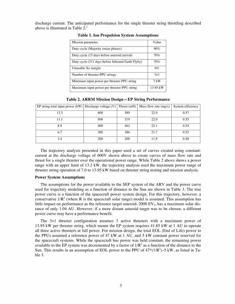
The ion propulsion subsystem (IPS) includes electric thrusters, power processor units (PPUs), xenon (Xe) storage, Xe flow control hardware, and mechanical thruster-gimbals to control the direction of the thrust vector from each individual electric thruster. Table 1 lists the assumptions for the ion propulsion system as applied to the trajectory design.
The nominal thruster configuration of the ARV for the reference trajectory of 3+1 assumed three active and 1 spare PPU/thruster string. A duty cycle of 90% is assumed on the trajectory modeling to allow for missed thrust and other non-thrusting operations. The duty cycle is reduced to 70% on the last 15 days prior to asteroid arrival to allow for observation and characterization of the asteroid on approach. The duty cycle is again reduced from 90% to 70% for 211 days on approach to the coast before the Earth flyby on the return leg of the trajectory. A Xe margin of 6% of the useable Xe is carried as an additional inert mass in the trajectory modeling to account for mission ΔV margin and trapped residuals.
The mission design of the interplanetary trajectory assumed the thruster performance generat-ed by the use of a constant discharge current (20.8 A) with power throttling between 300 to 600 V discharge voltages and a constant discharge voltage (300 V) with power throttling between 10.4 to 20.8 A discharge currents. Trajectory design for the Planetary Defense Demonstration (PDD) portion of the asteroid operations, which occur at the asteroid after the boulder is collected, as-sumed thruster performance set by a single operating point at 300 V discharge voltage and 10.4 A
3
discharge current. The anticipated performance for the single thruster string throttling described above is illustrated in Table 2.2
Table 1. Ion Propulsion System Assumptions Mission parameter Value
Duty cycle (Majority cruise phases) 90%
Duty cycle (15 days before asteroid arrival) 70%
Duty cycle (211 days before Inbound Earth Flyby) 70%
Unusable Xe margin 6%
Number of thruster-PPU strings 3+1
Minimum input power per thruster-PPU string 7 kW
Maximum input power per thruster-PPU string 13.95 kW
Table 2. ARRM Mission Design—EP String Performance
EP string total input power (kW) Discharge voltage (V) Thrust (mN) Mass flow rate (mg/s) System efficiency
13.3 600 589 22.9 0.57
11.1 500 519 22.0 0.55
8.9 400 462 22.1 0.54
6.7 300 386 21.7 0.52
3.4 200 200 11.9 0.49
The trajectory analysis presented in this paper used a set of curves created using constant-
current at the discharge voltage of 600V shown above to create curves of mass flow rate and thrust for a single thruster over the operational power range. While Table 2 above shows a power range with an upper limit of 13.3 kW, the trajectory analysis used the maximum power range of thruster string operation of 7.0 to 13.95 kW based on thruster string testing and mission analysis.
Power System Assumptions
The assumptions for the power available to the SEP system of the ARV and the power curve used for trajectory modeling as a function of distance to the Sun are shown in Table 3. The true power curve is a function of the spacecraft power system design. For this trajectory, however, a conservative 1/R2 (where R is the spacecraft solar range) model is assumed. This assumption has little impact on performance as the reference target asteroid, 2008 EV5, has a maximum solar dis-tance of only 1.04 AU. However, if a more distant asteroid target was to be chosen, a different power curve may have a performance benefit.
The 3+1 thruster configuration assumes 3 active thrusters with a maximum power of 13.95 kW per thruster string, which means the EP system requires 41.85 kW at 1 AU to operate all three active thrusters at full power. For mission design, the total EOL (End of Life) power to the PPUs assumed a reference power of 47 kW at 1 AU, and 5 kW constant power reserved for the spacecraft systems. While the spacecraft bus power was held constant, the remaining power available to the EP system was decremented by a factor of 1/R2 as a function of the distance to the Sun. This results in an assumption of EOL power to the PPU of 47*(1/R2)–5 kW, as listed in Ta-ble 3.

4
Table 3. Power System Assumptions Mission parameter Value
Spacecraft bus power while thrusting 5 kW
Solar array power curve 1/R2
EOL power to the PPU at 1 AU (3+1) 47*(1/R2)-5 kW
Table 4. Hydrazine and Xe Assumptions Propellant parameter Value
Additional hydrazine usage assumptions
Hydrazine propellant BOM 400 kg
Hydrazine used at launch 69.4 kg
Hydrazine used on outbound cruise 8.64 kg
Hydrazine used at target 271.65 kg
Hydrazine used on inbound cruise 10.84 kg
Hydrazine used for NRHO orbit maintenance 26.38 kg
Hydrazine retained through end of mission 13.09 kg
Additional Xe usage assumptions
Xe used at launch Calculated from 100 m/s ΔV (estimated at ~40 kg for Delta IV H)
Xe used at IPS checkout and calibration 64.6 kg
Xe used at target for PDD 303.3 kg
Xe used at Earth return Calculated from 130 m/s ΔV
Additional Xe and Hydrazine Assumptions
The ARV carried both hydrazine and Xe propellant for the RCS (Reaction Control System) and IPS, respectively. An allocation of 400 kg hydrazine is assumed to be the usable propellant to perform all RCS maneuvers throughout the mission and does not include residual or other non-usable propellant. This propellant is modeled as dropped masses at the end of phases along the reference trajectory. For example, propellant used to target the outbound lunar gravity assist (LGA) maneuvers is dropped before Earth escape, and hydrazine used in outbound cruise is mod-eled as a dropped mass at the end of the outbound cruise trajectory leg. An additional Xe mass is carried throughout the interplanetary phase as an inert mass to perform the ΔV on Earth return to insert the ARV and boulder into the Near Rectilinear Halo Orbit (NRHO). This propellant is cal-culated from the total mass of the ARV and Boulder combination and the assumed ΔV to perform the return orbit maneuvers. The propellant allocations and assumptions are captured in Table 4.
Spacecraft Mass Assumptions
The ARV dry mass in Table 5 has been fixed at a set value for the design of this reference tra-jectory in order to maximize the returned boulder mass. Also referred to as neutral mass, it is as-sumed that this spacecraft dry mass would include the capture mechanism, all subsystem contin-gency, trapped hydrazine residuals and system margin. For the reference trajectory documented here, the ARV dry mass was assumed to be 5500 kg.
5
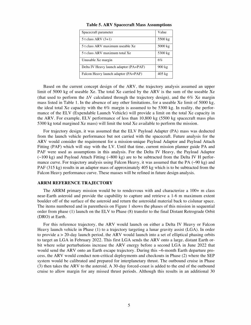
Table 5. ARV Spacecraft Mass Assumptions Spacecraft parameter Value
5 t class ARV (3+1) 5500 kg
5 t class ARV maximum useable Xe 5000 kg
5 t class ARV maximum total Xe 5300 kg
Unusable Xe margin 6%
Delta IV Heavy launch adaptor (PA+PAF) 900 kg
Falcon Heavy launch adaptor (PA+PAF) 405 kg
Based on the current concept design of the ARV, the trajectory analysis assumed an upper
limit of 5000 kg of useable Xe. The total Xe carried by the ARV is the sum of the useable Xe (that used to perform the DV calculated through the trajectory design), and the 6% Xe margin mass listed in Table 1. In the absence of any other limitations, for a useable Xe limit of 5000 kg, the ideal total Xe capacity with the 6% margin is assumed to be 5300 kg. In reality, the perfor-mance of the ELV (Expendable Launch Vehicle) will provide a limit on the total Xe capacity in the ARV. For example, ELV performance of less than 10,800 kg (5500 kg spacecraft mass plus 5300 kg total margined Xe mass) will limit the total Xe available to perform the mission.
For trajectory design, it was assumed that the ELV Payload Adapter (PA) mass was deducted from the launch vehicle performance but not carried with the spacecraft. Future analysis for the ARV would consider the requirement for a mission-unique Payload Adaptor and Payload Attach Fitting (PAF) which will stay with the LV. Until that time, current mission planner guide PA and PAF were used as assumptions in this analysis. For the Delta IV Heavy, the Payload Adaptor (~100 kg) and Payload Attach Fitting (~800 kg) are to be subtracted from the Delta IV H perfor-mance curve. For trajectory analysis using Falcon Heavy, it was assumed that the PA (~90 kg) and PAF (315 kg) results in an adaptor mass of approximately 405 kg which is to be subtracted from the Falcon Heavy performance curve. These masses will be refined in future design analysis.
ARRM REFERENCE TRAJECTORY
The ARRM primary mission would be to rendezvous with and characterize a 100+ m class near-Earth asteroid and provide the capability to capture and retrieve a 1-6 m maximum extent boulder off of the surface of the asteroid and return the asteroidal material back to cislunar space. The items numbered and in parenthesis on Figure 1 shows the phases of this mission in sequential order from phase (1) launch on the ELV to Phase (8) transfer to the final Distant Retrograde Orbit (DRO) at Earth.
For this reference trajectory, the ARV would launch on either a Delta IV Heavy or Falcon Heavy launch vehicle in Phase (1) to a trajectory targeting a lunar gravity assist (LGA). In order to provide a > 20-day launch period, the ARV would launch into a set of elliptical phasing orbits to target an LGA in February 2022. This first LGA sends the ARV onto a large, distant Earth or-bit where solar perturbations increase the ARV energy before a second LGA in June 2022 that would send the ARV onto an Earth escape trajectory. During this ~6-month Earth departure pro-cess, the ARV would conduct non-critical deployments and checkouts in Phase (2) where the SEP system would be calibrated and prepared for interplanetary thrust. The outbound cruise in Phase (3) then takes the ARV to the asteroid. A 30-day forced-coast is added to the end of the outbound cruise to allow margin for any missed thrust periods. Although this results in an additional 30

6
days at the asteroid in this reference trajectory, that time period is margin on the outbound cruise and is not available to the asteroid operations phase.
Figure 1. ARRM Mission Overview
For the purpose of the trajectory modeling, there are 385 days allocated for asteroid operations in Phase (4). Of this, 15 days are modeled as the asteroid approach under SEP thrust and is de-ducted from the asteroid stay time for the purposes of trajectory modeling, leaving 370 days at the asteroid. When this resulting 370-day stay time is added to the 30-day forced coast for missed thrust in the outbound cruise that results in a 400-day stay time for trajectory modeling.
Inbound cruise in Phase (5) then takes the combined ARV and boulder back to Earth. There is an Earth flyby one year before an LGA that captures the ARV-boulder combination into the Earth-Moon system. After capture, solar and lunar perturbations are used in the endgame phase in Phase (6) to transfer to a crew-accessible orbit in Phase (7). In this example trajectory, the ARV would target a crew-accessible, Lunar Near-Rectilinear Halo Orbit for the Asteroid Redirect Crew Mission (ARCM) which would send astronauts in an Orion spacecraft to rendezvous and dock with the ARV. After the ARCM, the ARV would transfer to a Lunar Distant Retrograde Orbit (DRO) in Phase (8) with an orbit lifetime in excess of 100 years for storage of the returned boulder. The final orbits for both the human phase of the ARM and the final storage orbit for the asteroid being considered in the reference trajectory are NRHO and DRO orbits.3
Earth Departure
Two lunar flybys, together with solar perturbations, are used to boost the spacecraft hyperbolic escape C3 to 1.7 km2/s2, for a modest increase in flight time. The main advantage of this approach is that it tolerates a negative launch C3 of –2 km2/s2 (an energy sufficient to reach the Moon),
7
which increases the maximum mass of the spacecraft at Earth escape compared to a direct escape strategy. The first LGA would send the ARV onto a large, distant Earth orbit where solar pertur-bations would increase the ARV energy before a second LGA in June 2022 that would send the ARV onto an Earth escape trajectory. No deterministic maneuvers are required between the two LGAs. Different approaches for designing the two LGAs are presented in Ref. 4. The trajectory is mostly independent of the LV; for the final reference trajectory documented in this paper, it was assumed that the SEP Asteroid Redirect Vehicle (ARV) would launch on either a Delta IV Heavy or Falcon Heavy launch vehicle.
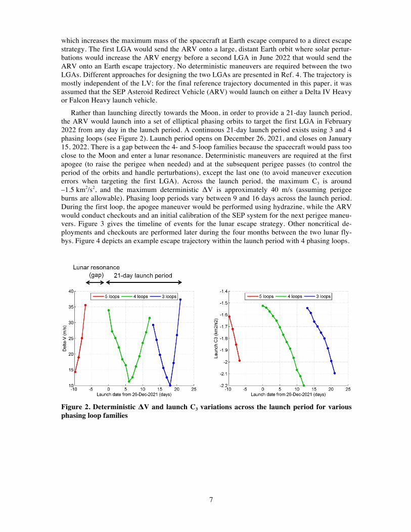
Rather than launching directly towards the Moon, in order to provide a 21-day launch period, the ARV would launch into a set of elliptical phasing orbits to target the first LGA in February 2022 from any day in the launch period. A continuous 21-day launch period exists using 3 and 4 phasing loops (see Figure 2). Launch period opens on December 26, 2021, and closes on January 15, 2022. There is a gap between the 4- and 5-loop families because the spacecraft would pass too close to the Moon and enter a lunar resonance. Deterministic maneuvers are required at the first apogee (to raise the perigee when needed) and at the subsequent perigee passes (to control the period of the orbits and handle perturbations), except the last one (to avoid maneuver execution errors when targeting the first LGA). Across the launch period, the maximum C3 is around –1.5 km2/s2, and the maximum deterministic ΔV is approximately 40 m/s (assuming perigee burns are allowable). Phasing loop periods vary between 9 and 16 days across the launch period. During the first loop, the apogee maneuver would be performed using hydrazine, while the ARV would conduct checkouts and an initial calibration of the SEP system for the next perigee maneu-vers. Figure 3 gives the timeline of events for the lunar escape strategy. Other noncritical de-ployments and checkouts are performed later during the four months between the two lunar fly-bys. Figure 4 depicts an example escape trajectory within the launch period with 4 phasing loops.
Figure 2. Deterministic ΔV and launch C3 variations across the launch period for various phasing loop families

8
Figure 3. Timeline of lunar flyby events during Earth departure phase
Figure 4. Example of escape trajectory in Sun-Earth rotating frame
Outbound Cruise Leg The outbound cruise leg of the trajectory starts at the post LGA Earth escape condition of
C3 = +2 km2/s2, and continues until the ARV is in the vicinity of the asteroid. The ARV reaches Earth escape approximately 167 days after a December 26, 2021 launch. Operating at 90% duty cycle, the ARV uses the SEP system to perform the 425-day outbound cruise leg to the asteroid. The duty cycle is chosen as a time margin during the cruise in order to allow for missed thrust recovery. During the outbound cruise leg, the SEP thrusting is largely out of plane in order to move from the ecliptic up to the inclined plane (~7.4°) of 2008 EV5. On the final 15 days before reaching the asteroid, the SEP duty cycle is dropped to 70% to allow for asteroid characterization operations. The trajectory must maintain a solar phase angle of less than 60°, for optical naviga-tion purposes, once asteroid range is less than 250,000 km. The interplanetary trajectory is mod-eled to arrive at the asteroid at a 2000 km offset distance with a relative velocity of 8.2 m/s and 45° phase angle. The complete state for this handoff point, in the Sun-Asteroid synodic frame, is given in Table 6.

9
Upon arrival at the asteroid, the ARV performs scientific analysis to characterize the asteroid. After characterization is complete, the characterization team uses the data to select five sites on the surface of the asteroid as potential boulder retrieval options. There are 370 days currently allocated to complete these asteroid operations. During asteroid operations, minimal SEP thrusting would be performed as the boulder is selected, captured and retrieved from the surface of the asteroid.
Figure 5 depicts the heliocentric trajectory in the EMO2000 frame. The Sun is located at the “X” in the center of the plot. The major events of Earth departure, asteroid arrival, asteroid depar-ture, Earth flyby on return and Earth arrival are annotated in the graphic. The light grey orbit is that of 2008 EV5. In keeping with the coloring scheme of the plots in this section, the blue trajec-tory lines are the outbound leg from the Earth to 2008 EV5 and the red trajectory lines are the in-bound trajectory leg from 2008 EV5 to the Earth. The Earth’s orbit is also shown in blue, per the default coloring scheme of the trajectory tool used to perform this analysis (Copernicus), but can be ascertained by locating the Earth departure and arrival labels on the plot.
Table 6. ARV Asteroid Delivery State (Sun-Asteroid Synodic Frame) X (km) Y (km) Z (km) Vx (m/s) Vy (m/s) Vz (m/s)
–1,414.213 –1,414.213 0 7.075 3.551 2.266
Figure 5. ARRM trajectory to 2008 EV5 in heliocentric space

10
Inbound Cruise Leg
The inbound cruise leg of the trajectory returns the combined ARV and boulder back to Earth. The ARV uses SEP to execute the low thrust trajectory from 2008 EV5 to target the LGA at Earth return. In order to perform the plane change from the 7.4° inclined plane of 2008 EV5 back down to the ecliptic plane, an Earth flyby was targeted 1-year before Earth return. This Earth Flyby provides both energy to the trajectory as well as a plane change. For most of the 608-day return to Earth, the trajectory is modeled with the SEP system operating at a 90% duty cycle. A reduced duty cycle of 70% is enforced for 211 days prior to the inbound Earth flyby for missed thrust margin, and a 7-day forced coast is inserted into the trajectory prior to the Earth flyby for naviga-tion purposes. An additional final forced coast is inserted into the inbound cruise leg 60 days (30 days for missed thrust margin and 30 days for navigation) prior to Earth return. The target Earth arrival state, in the Earth-centered EMO2000 frame, is shown in Table 7. After Earth return on July 28, 2026, the final Endgame phase of the mission begins.
Table 7. Earth Arrival State in Earth-Centered EMO2000 Frame
Epoch (ET) 0.83848914479364×10⁹
X (km) –5.570726262048531×10⁴
Y (km) –1.306474991146711×10⁵
Z (km) –3.498142685668100×10⁴
Vx (km/s) 2.060740324514976×10
Vy (km/s) –1.770469193129591×10
Vz (km/s) 1.530969197764400×10⁻²
Endgame For Earth return, an LGA is targeted to loosely capture the ARV-boulder combination into the
Earth-Moon system. Solar perturbations are then exploited to reduce the relative velocity with the Moon and transfer the ARV and boulder to a crew-accessible orbit. The solar loop typically lasts 3 months and is quasi-ballistic. Short low-thrust burns are performed around the Moon to insert the ARV and boulder into the crew-accessible orbit. In this example trajectory, the ARV would target a crew-accessible NRHO. This particular orbit is in 9:2 resonance with the Moon (9 NRHO revolutions for every 2 lunar periods) with a period of 6.6 days. The insertion date is December 12, 2026. Figure 6 and Figure 7 illustrate the reference trajectory of the endgame and NRHO in-sertion phases. The total deterministic ΔV is only 18 m/s (endgame DV = 4 m/s, NRHO insertion DV = 14 m/s). Thanks to the 9:2 resonance of the NRHO orbit, long eclipses by the Earth can be avoided.5 All eclipses by the Moon are less than 90 min, which meets the flight system require-ments. After insertion, the Asteroid Redirect Crew Mission (ARCM) can be executed, which would send astronauts in an Orion spacecraft to rendezvous and dock with the ARV. After ARCM (at most 1 year after NRHO insertion), the ARV would transfer to a Lunar Distant Retro-grade Orbit (DRO) with an orbit lifetime in excess of 100 years for storage of the returned boul-der. The methodology to design this NRHO to DRO transfer is described in detail in Ref. 6.

11
Figure 6. Endgame and NRHO insertion in Earth-centered inertial frame (EMO2000)
Figure 7. NRHO insertion in Earth-Moon synodic frame reference mission event highlights
The relevant major mission events throughout the reference trajectory are captured in Table 8. Solar distances and Earth ranges (both presented in AU) are included for future power system and communication system analysis. All items are measured in terms of mission elapsed time (MET) from launch. The total mass at each mission events shows the decrease in mass from the con-sumption of Xe and/or hydrazine along the trajectory and the increase in mass due to the acquisition of the boulder mass at the asteroid. For example, the mass at arrival to the asteroid is 8432.8 kg and at departure from the asteroid is 21,385 kg. This difference is a combination of boulder mass in-creasing the total mass as well as Xe and hydrazine use at the asteroid for operations.

12
Table 8. Reference Trajectory Mission Event Highlights
Mission event Date Solar distance RSun (AU)
Earth distance REarth (AU)
Total mass (kg)
MET (days)
Launch window open 26-Dec-2021 0.983 4.39×10⁻⁵ 10895 –167
Launch 26-Dec-2021 0.983 4.39×10⁻⁵ 9995
Lunar flyby 1 20-Feb-2022 0.990 2.51×10⁻³ 9821.9 –111
Lunar flyby 2 9-Jun-2022 1.016 2.55×10⁻³ 9821.9 –2
Earth departure 11-Jun-2022 1.015 5.943×10⁻⁴ 9821.9 0
70% duty cycle on approach to asteroid 10-Aug-2023 0.891 0.424 8496 425
Arrival at asteroid 25-Aug-2023 0.887 0.405 8432.8 440
Begin asteroid operations 24-Sep-2023 NA NA NA 470
Departure from asteroid 28-Sep-2024 0.908 0.294 21385.2 840
Begin reduced duty cycle for missed thrust (70%) 27-Nov-2024 0.987 0.345 21081.6 900
Begin coast on Earth flyby approach 20-May-2025 1.044 0.079 20362.7 1074
Earth flyby (end reduced duty cycle) 25-Jun-2025 1.017 0.000 20362.7 1110
Begin coast on final Earth approach 29-May-2026 0.950 0.072 19414.5 1448
Earth arrival 28-Jul-2026 1.016 0.001 19403.7 1508
Capture LGA 30-Jul-2026 1.018 2.67×10⁻³ 19403.7 1510
Lunar capture / begin NRO insertion 31-Oct-2026 0.994 2.60×10⁻³ 19398.7 1603
ARCM rendezvous 12-Dec-2026 0.982 2.85×10⁻³ 19383.8 1645
Final DRO 20-Oct-2028 0.993 2.50×10⁻³ 19294.5 2323
Table 9. Reference Trajectory Mass Highlights
Item Mass (kg) Notes
Delta IV H Delivered mass 10894 Performance to C3 = –1.5 km2/s2
Spacecraft adaptor (PA/PAF) 900 Allocation mass for PA/PAF, subtracted from Performance
Fixed maximum ARV Dry mass 5500 Assumed fixed ARV dry mass. 10% growth from July 2016 reference
Hydrazine BOM 400 Allocation of hydrazine mass for mission
Xe mass (total, including 6%) 4095 Xe mass limited by Delta IV H performance
Spacecraft mass at Launch 9995 Sum of ARV dry, Hydrazine, and Xe masses
Asteroid Mass returned (maximized) 13535 Maximized boulder mass returned
Reference Mission Mass Highlights
For the major mass calculations throughout the reference trajectory, several relevant mass pa-rameters are identified and captured in Table 9. The total spacecraft mass at launch is the sum of the ARV dry mass, hydrazine allocation, and total Xe mass. The total Xe mass capacity is calculated by subtracting the PA/PAF, ARV dry mass and hydrazine allocation from the total Delta IV H perfor-mance to C3 of –1.5 km2/s2. Assuming a spacecraft dry mass of 5500 kg, and a total Xe mass (the

13
sum of useable Xe and 6% margin) limited by the capability of the launch vehicle at 4095 kg, the total asteroidal mass returned is maximized in the trajectory design to be 13,535 kg.
MISSION DESIGN OBSERVATIONS
The ARRM mission presented several challenges in trajectory design and modeling. The over-all spacecraft mass and launch vehicle performance capability assumptions directly impacted the amount of propellant the ARV spacecraft could carry. This propellant mass was directly linked to the mass of the boulder that could be returned from the asteroid 2008 EV5. Both the choice of launch date and the asteroid stay time also affected the returned boulder mass capability of the end to end ARRM trajectory.7 In addition, spacecraft system requirements were levied on the tra-jectory design, such as the requirement to fly no closer than 0.8 AU distance to the Sun and to limit the power to the SEP system at no more than 40 kW at 1 AU. Several segments of the end to end trajectory were sensitive to missed thrust events including the period of coasting preceding the inbound Earth flyby.
Reference Trajectory Plots
All data presented below is plotted vs. mission date, starting from the nominal Earth departure date (i.e., the end of the second LGA) of June 11, 2022. In all plots, the blue lines represent the output trip to the asteroid, the red lines are the inbound trip from the asteroid, and the green shad-ed section indicates position when the ARV is at the asteroid. Grey shaded areas are periods of coast throughout the trajectory.
In Figure 8, r(au)[J2000-EARTH] is the absolute magnitude of the distance from the ARV to the Earth, measured in AU.
Figure 9 shows r(au)[J2000-SUN], which is the absolute magnitude of the distance from the ARV to the Sun, measured in AU. Figure 10 shows the power to the EP system (i.e., input power to the PPUs) throughout the mission dates. As the ARV’s trajectory goes away from 1 AU from the Sun, the power to the thrusters decreases as a function of 1/R2. When the trajectory is closer to the Sun than 1 AU, no additional power is used, as the EP system is limited to a total power of 42 kW.
Figure 8. Distance to Earth (AU) vs. mission date

14
Figure 9. Distance to Sun (AU) vs. mission time
Figure 10. Power to the EP system vs. mission time
Missed Thrust
Mission design does not carry any Xe margin for missed thrust, rather forced coast and re-duced thrust duty cycle periods are used to provide missed thrust margin before crucial mission events.8 A duty cycle of 90% throughout the main cruise legs of the mission is used. The duty cycle is reduced 70% for the 15 days of final approach to the asteroid to allow timeline margin for the later design of approach phase activities. The duty cycle is also reduced to 70% for 211 days prior to the inbound Earth flyby. It is assumed that radiometric tracking of the ARV is possible while thrusting. While analysis had been initiated in order to understand the impact that missed thrust had on the reference trajectory, much work remained to be completed.

15
Application of Different Trajectory Tools
The reference trajectory documented in this paper and used as the formally documented trajec-tory for the ARRM design team was modeled in the trajectory tool, Copernicus.9 Copernicus de-velopment started at the University of Texas at Austin and currently continues at Johnson Space Center (JSC).10 Copernicus is a generalized spacecraft trajectory design and optimization tool, capable of designing low thrust and impulsive trajectory problems. Copernicus is an n-body tool and is considered high fidelity. The high-fidelity capabilities of Copernicus made possible model-ing such details as targeting a specific state in the vicinity of the asteroid arrival and targeting a state to set up the Earth return endgame.
At the time of the development of this reference trajectory, the mission design team was con-verting the Copernicus reference to the JPL high fidelity tool Mystic. Mystic is a high-fidelity optimization and simulation program capable of low thrust trajectory modeling that uses a Static/Dynamic optimal control (SDC) method to perform nonlinear optimization. Mystic is an n-body tool and can analyze interplanetary missions as well as planet-centered missions in complex gravity fields. Mystic is currently being used on the Dawn mission.
Additional tools were used to provide trade space scoping analysis and to provide initial guesses for the reference trajectory. Specifically, MALTO (The Mission Analysis Low-Thrust Optimization)11 and EMTG (Evolutionary Mission Trajectory Generator)12 were employed as medium fidelity tools well-suited for identifying the initial trajectory for subsequent refinement in Copernicus. MALTO and EMTG are both based on the same Sims-Flanagan, direct trajectory transcription13 in which trajectory arcs are segmented and an impulsive DV at each segment mid-point approximates a continuous low-thrust arc. The DV is limited by the available thrust over the duration of the segment, and Kepler propagation is incorporated between segment midpoints for optimization efficiency.
EMTG exploits a global-local hybrid scheme, to enable a global trajectory search without a user-defined initial guess. The global search is achieved via an outer loop based on monotonic basin hopping, while a sequential quadratic programming routine, SNOPT,14 provides local, gra-dient based inner-loop refinement. Systems optimization of parameters such as solar array power, the number of thrusters, thruster model/type, and the launch vehicle is also available with a multi-objective genetic algorithm (GA) outer loop.15 The outer-loop systems optimizer enables efficient trading of both trajectory and spacecraft hardware parameters that are intrinsically coupled to the trajectory for broad trade evaluations. EMTG proved to be particularly adept at problems when the solution is not known a priori, as it avoids local minima traps when evaluating sensitivity.
CONCLUSION
The use of a low thrust Solar Electric Propulsion system made possible the ARRM mission concept to travel to an asteroid and return back a substantial mass to an orbit about the Moon. The high-power, light-weight solar arrays and high-power, magnetically-shielded hall thrusters being developed for ARRM would dramatically increase NASA’s in-space transportation capability. This paper captures the last reference trajectory generated for the ARRM mission. This trajectory was the culmination of years of iterations of power level, thruster performance assumptions, missed thrust analysis, and asteroid returned mass sensitivity studies.
ACKNOWLEDGMENTS
The authors wish to express their gratitude to the management of the ARRM project as well as their own management at NASA GRC, JPL, NASA LaRC and NASA GSFC. Special thanks to

16
Brian Muirhead (JPL), ARRM Project Manager, for his leadership and faith and for always com-ing up with new and interesting problems for us to solve. Even though we pause for now on de-signing the Asteroid Robotic Redirect Mission, we are hopeful that the groundwork we’ve laid will be used someday for magnificent science and technology development as well as enable fu-ture human exploration.
REFERENCES 1 J. Brophy and B. Muirhead, “Near-Earth Asteroid Retrieval Mission (ARM) Study,” Presented at the 33rd Interna-tional Electric Propulsion Conference, Washington, DC, October 6–10, 2013. IEPC-2013-82. 2 D.A. Herman, W. Santiago, H. Kamhawi, J.E. Polk, J.S. Snyder, R.R. Hofer, and M.J. Sekerak, “The Ion Propulsion System for the Asteroid Redirect Robotic Mission,” Propulsion and Energy Forum, 52nd AIAA/SAE/ASEE Joint Pro-pulsion Conference, July 25-27, 2016, Salt Lake City, UT, AIAA-2016-4824. 3 R. Whitley and R. Martinez, “Options for Staging Orbits in Cislunar Space,” IEEE Aerospace 2015, Mar. 2015. 4 L. Casalino, G. Lantoine, “Design of Lunar-Gravity-Assisted Escape Maneuvers,” 28th AAS/AIAA Space Flight Mechanics Meeting, Aug. 2017. 5 J. Williams, D.E. Lee, R.L. Whitley, K.A. Bokelmann, D.C. Davis, and C.F. Berry, “Targeting Cislunar Near Recti-linear Halo Orbits for Human Space Exploration,” 27th AAS/AIAA Space Flight Mechanics Meeting, Feb. 2017. 6 G. Lantoine, “Efficient NRHO to DRO transfers in cislunar space,” 28th AAS/AIAA Space Flight Mechanics Meet-ing, Aug. 2017. 7 M. McGuire, L. Burke, S. McCarty, N. Strange, M. Qu, H. Shen and M. Vavrina, “Sensitivity of the Asteroid Redirect Robotic Mission (ARRM) to Launch Date and Asteroid Stay Time,” 27th AAS/AIAA Space Flight Mechanics Meet-ing; San Antonio, TX, 5-9 Feb. 2017. 8 D. Oh, D. Landau, T. Randolph, P. Timmerman, J. Case, J. Sims, and T. Kowalkowski, “Analysis of System Margins on Missions Utilizing Solar Electric Propulsion,” 44th AIAA/ASME/SAE/ASEE Joint Propulsion Conference & Ex-hibit ; Hartford, CT; 21-23 Jul. 2008. 9 C. Ocampo, J. Senent, “The Design and Development of COPERNICUS: A Comprehensive Trajectory Design and Optimization System”, Paper IAC-06-C1.4.04, Oct. 2006. 10 Williams, J., “Copernicus Trajectory Design and Optimization System,” NASA. NASA, 3 Nov. 2016. Web. 11 Jan. 2017. https://www.nasa.gov/centers/johnson/copernicus/index.html. 11 J. Sims, P. Finlayson, E. Rinderle, M. Vavrina, and T. Kowalkowski, “Implementation of a Low-Thrust Trajectory Optimization Algorithm for Preliminary Design,” AIAA/AAS Astrodynamics Specialist Conference, Keystone, CO, August 2006. 12 J. Englander and B. Conway, “An Automated Solution of the Low-Thrust Interplanetary Trajectory Problem,” Jour-nal of Guidance, Control, and Dynamics, Vol. 40, No. 1 (2017), pp. 15-27. 13 J. Sims, and S. Flanagan, “Preliminary Design of Low-Thrust Interplanetary Missions,” AAS/AIAA Astrodynamics Specialist Conference, Girdwood, AK, August 1999. 14 P, Gill, P.E., W. Murray, and M. Saunders, "SNOPT: An SQP algorithm for large-scale constrained optimization." SIAM journal on optimization, Vol. 12 No. 4, 2002, pp. 979-1006. 15 M. Vavrina, J. Englander, and A. Ghosh, “Coupled Low-Thrust Trajectory and Systems Optimization via Multi-objective Hybrid Optimal Control,” AAS/AIAA Space Flight Mechanics Meeting Williamsburg, VA, January 2015.


![S S S - physics.umd.edu Notation in... · Configuration . Term . J . Level (eV) 1s2. ... electron mass proton mass fine-structure constant ... [Xe]4f66s2 5.6437 7F pu Plutonium](https://img.pdfslide.net/doc/110x75/5b6b1a407f8b9a9f1b8d06f6/s-s-s-notation-in-configuration-term-j-level-ev-1s2-electron.jpg)