Embed Size (px)
Citation preview
SEATPA-PM-000245
ABB DRIVES AND CONTROL SYSTEM FOR HOT FLAT ROLLING
MILLS IMPROVES YIELD AND QUALITY
BY
LARS MJÖRNING *
SYNOPSIS:
ABB have through the years delivered a large number of drive and control systems to rolling mills in the steel industry, helping mill crews to produce rolled material with a higher effiency and improved yield and quality.
ABB have developed software applications covering most advanced control applications in Rolling Mills supporting all mill crew to optimize quality and utilization of the mill. Those applications are implemented in the newly developed control system 800xA.
ABB’s new generation of control is an open system that provides a complete integration of advanced process control, supervision of equipment, production planning and follow up.
Rolling mill drive systems must meet very demanding requirements. To fulfill those, ABB has developed a new type of converter to feed synchronous or induction AC-motors. The new DTC (Direct Torque Control) Drive control improves dynamic performance by magnitudes compared to conventional solutions. The converter has a unity power factor loading of the power supply, why no SVC is required.
The paper describes ABB Process Control System for Hot Flat Mills including ABB Drive and Automation Systems, with examples from installations in Rolling Mills.
Keywords: Rolling Mill Applications, Rolling Mill Control System, Rolling Mill Drive Systems, Industrial IT
* Marketing Manager, Rolling Mills, ABB Automation Technologies, Västerås, Sweden.
Page of 14 1

SEATPA-PM-000245
Rolling Mill control system Industrial IT System 800xA supports the core processes of the Metals Industries value chain.
Software architecture ABB’s System 800xA has a unique software architecture known as AspectObjects. This organizes the automation system into Objects and each of which has characteristics defined as Aspects.
• Objects: are devices, products, orders, etc..
• Aspects: are real-time properties that relates to the object.
Actually, you may have already had some experience with these concepts . . .
Most of you have had the experience of installing a new printer for your PC. A job made much easier since all the information you need (fonts, drivers, diagnostic software, etc.) is provided with the product on a CD ROM. (See Fig. 1)
These various files are the Aspects of the printer.The architecture is developed so that information from automation systems from other suppliers can be easily integrated into the ABB System 800xA. The Objects are arranged in a Plant Explorer structure based on either functionality or geographic location. This provides the big advantage for the mill crew that all information about the process objects such as drawings, descriptions, handbooks, maintenance statistics, etc. are immediately on hand when required. No more searching for documentation while production is waiting. Additional information can be added into the system for the most part irrespective of the form of the information. The basic goal of System 800xA is to enable many products to work together in truly seamless fashion, creating a total solution that is far greater than the sum of its parts, much the way the various programs on your PC work together to make the job easier.
ABB’s commitment is to provide similar information in standard electronic formats with our motors, drives, switchgear, instruments, etc. Depending on the product, up to 20 or more Aspects (characteristics) might be provided. Either directly with the product or via online links to other platforms. A common software program (.pdf for instructions; AutoCad for 2-D drawings, etc.) will always be used for each type of aspect. (See Fig. 2)
Page of 14 2

SEATPA-PM-000245
Together, these Aspects form a dynamic “model object” containing links to all the important information. In System 800xA terminology, this is called an Aspect Object.
Easy engineering So how does this make it easier to install, operate, and maintain the product?
When multiple products are combined to make a system or solution, physically putting each device into place is the easy part. The difficult part is collecting the information (configuration, drawings, maintenance records, etc.) which is often stored in different formats and in different locations, and then keeping it up to date.
System 800xA changes this. Once the physical device is put into place, the operator can simply copy and paste the model Aspect Object into the overall system monitoring and control strategy. No matter where each real object is deployed, one “click” on the model Object provides a link to its Aspect information. (See Fig. 3)
Although certain Aspects (drawings, instructions, etc.) may not change over time, other dynamic Aspects (configuration, efficiency, cost of ownership) must be frequently updated.
Page of 14 3

SEATPA-PM-000245
Let’s take a closer look at some examples of ObjectsAspects.
Data need be entered only once for use throughout the system, and real-time information on each Object is just a “click” away. (See Fig. 4)
In addition to managing system devices as shown here, the System 800xA Architecture will also support management of Aspect Objects based on end products. For example, each slab, coil, or plate has real-time characteristics such as raw material composition, end customer, lot number, delivery date, etc..
Integrated systems Thanks to the multi-faceted System 800xA architecture (See Fig. 5), this added value will extend across many dimensions of the business enterprise. The same 800xA components will offer:
- Vertical integration from the most basic devices to management decision support . . .
- Horizontal integration to ensure a consistent approach to similar tasks across the plant . . .
- Lifecycle support for business assets, from idea and installation, through operation and maintenance . . .
- And even Supply Chain integration that lets the user reach beyond their own business to interact with their own customers and suppliers.
Page of 14 4

SEATPA-PM-000245
- In the near term, System 800xA will bring significant benefits to the users, ranging from easier deployment of “information enabled” products to easier integration of products from multiple business areas.
Along the way, customers will find their plant operation is simplified through access to real-time information.
Fewer installed products will provide more choices, and productivity will be optimized, as System 800xA products interact and “learn” from each other.
In longer term, we believe the extension of 800xA to other product producers will offer customers a far greater choice of compatible technologies.
Control system for Hot Rolling Mills A typical basic configuration can be seen in Fig. 6.
Page of 14 5

SEATPA-PM-000245
The application software is built by a number of SW standard modules. The principle is shown in Fig. 7.
A few examples of such standardized application modules are shown in Fig. 8 and 9.
Page of 14 6

SEATPA-PM-000245
Rolling Mill Main Drive Technology
History
Rolling Mill Main Drive technology development
Figure 10 illustrates the history of speed controlled drives for large rolling mill drives where DC-motors was used until the beginning of the eighties when the introduction of the cycloconverter enabled the use of synchronous motors
The latest step, going from Cycloconverter drives to medium voltage source inverter drives were initialized by the introduction of a new generation of medium voltage power semiconductors, like the IGCT (Integrated Gate Controlled Thyristor). This was a great leap forward restoring some important features (like unity power factor operation, nearly sinusoidal loading of the power network, reactive power compensation capability and multi-drive capability or possibility to use common supply section). The prevailing large drive technology in all times is based on lowest total investment cost for the Rolling Mill owners. In the total investment cost the life time cost of power losses must be included.
Drive dynamics as fast torque and speed control has always been considered as a very important feature. Together with the new drive technology represented by ACS 6000SD and its feature of DTC (Direct Torque Control that’s gives an optimally fast torque control we are introducing RMD (Rolling Mill Drive) control, which replaces the conventional PI-speed control and conventional feed forward control techniques. The result is that we now can offer an optimally fast speed control based on the characteristics of the mechanical drive train.
The RMD control means that loading of the different mechanical parts of the drive train is lowered, which lowers the maintenance costs for the Mill owners.
Page of 14 7

SEATPA-PM-000245
The ACS 6000SD drive is a fuse-less drive available for reversing rolling mills. For Mill owners this means higher reliability since the fuses are suffering of thermal ageing, a phenomena where the root cause is the cyclic load of a reversing rolling mill, up to 250 % followed by no-load.
Impact on the power supply network Medium voltage source inverter drives supplied by active rectifiers (active front end) is a major breakthrough, compared with cycloconverter fed synchronous motor drive.
As described earlier is the loading and unloading best characterized as a step-function at load end of the drive-train. The load impact on the motor is lowered due to the elastic characteristic of the drive train.
In order to lower the forces on the mechanical system at threading, the speed is often lower than the desired rolling speed. The speed reference at threading can be between 30 – 50 % of nominal speed. At those speeds the power factor of the cycloconverter is really bad, maybe cos ϕ=0,3.
When the slab enters into the rolling mill the actual speed of the work rolls drops, because the speed controller needs time to build up the torque reference. This behavior is referred to as impact speed drop [%s]. The higher dynamic settings of the speed controller the faster is the torque build-up time and the smaller is the impact speed drop.
Cycloconverters are always accompanied in these applications by a SVC equipment. The traditional SVC is a number of passive harmonic filters and a TCR (Thyristor Controlled Reactor). The TCR is controlled so that it consumes the excessive reactive power produced by passive filters of the SVC. The idea with the SVC is to keep the power factor at unity independent of the actual load.
Efficiency comparison CC-SM vs. ACS 6000SD.
Page of 14 8
SEATPA-PM-000245
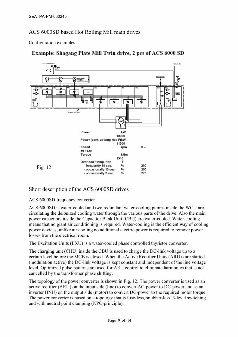
ACS 6000SD based Hot Rolling Mill main drives Configuration examples
Short description of the ACS 6000SD drives ACS 6000SD frequency converter
ACS 6000SD is water-cooled and two redundant water-cooling pumps inside the WCU are circulating the deionized cooling water through the various parts of the drive. Also the main power capacitors inside the Capacitor Bank Unit (CBU) are water-cooled. Water-cooling means that no giant air conditioning is required. Water-cooling is the efficient way of cooling power devices, unlike air cooling no additional electric power is required to remove power losses from the electrical room.
The Excitation Units (EXU) is a water-cooled phase controlled thyristor converter.
The charging unit (CHU) inside the CBU is used to charge the DC-link voltage up to a certain level before the MCB is closed. When the Active Rectifier Units (ARU)s are started (modulation active) the DC-link voltage is kept constant and independent of the line voltage level. Optimized pulse patterns are used for ARU control to eliminate harmonics that is not cancelled by the transformer phase shifting.
The topology of the power converter is shown in Fig. 12. The power converter is used as an active rectifier (ARU) on the input side (line) to convert AC-power to DC-power and as an inverter (INU) on the output side (motor) to convert DC-power to the required motor torque. The power converter is based on a topology that is fuse-less, snubber-less, 3-level switching and with neutral point clamping (NPC-principle).
Page of 14 9

SEATPA-PM-000245
ACS 6000SD control Control system
The control structure is similar to the structure that is used for the ABB low voltage AC drives ACS 800. This means that some control boards, like the pulse encoder interface, are used in both products.
The S800 standard I/O, which comes from the Control System 800xA, is used to handle the drive auxiliary functions like cooling, space heating, door locking system, start prevention switches, etc.
Drive HSI The panel and the PC-tools (DriveWindow and Drive Debug) is exactly the same type that is used for ABB low voltage AC-drives type ACS 800, and this represents an advantage for maintenance, as there are also many low voltage speed controlled drives in the same plant (See Fig. 13).
Drive panel and Drive Window PC tool.
Torque Control The inverters are using 3-level DTC switching to control the torque of the motors and to control the harmonics of the motor torque such as it not exciting any mechanical resonance’s. Here the randomness of the DTC is beneficial since it is smoothening the harmonic spectra of the airgap torque. DTC is a modulator free AC-motor control scheme, which has an extremely low dead time in the torque control loop. DTC is updating the switch positions every 25 µs based on a new evaluation of the motor airgap torque that is based on new voltage and current measurements.
Page of 14 10
SEATPA-PM-000245
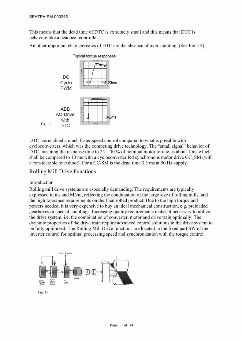
This means that the dead time of DTC is extremely small and this means that DTC is behaving like a deadbeat controller.
An other important characteristics of DTC are the absence of over shooting. (See Fig. 14)
DTC has enabled a much faster speed control compared to what is possible with cycloconverters, which was the competing drive technology. The “small signal” behavior of DTC, meaning the response time to 25 – 30 % of nominal motor torque, is about 1 ms which shall be compared to 10 ms with a cycloconverter fed synchronous motor drive CC_SM (with a considerable overshoot). For a CC-SM is the dead time 3.3 ms at 50 Hz supply.
Rolling Mill Drive Functions
Introduction Rolling mill drive systems are especially demanding. The requirements are typically expressed in ms and MNm, reflecting the combination of the large size of rolling mills, and the high tolerance requirements on the final rolled product. Due to the high torque and powers needed, it is very expensive to buy an ideal mechanical construction, e.g. preloaded gearboxes or special couplings. Increasing quality requirements makes it necessary to utilize the drive system, i.e. the combination of converter, motor and drive train optimally. The dynamic properties of the drive train require advanced control solutions in the drive system to be fully optimized. The Rolling Mill Drive functions are located in the fixed part SW of the inverter control for optimal processing speed and synchronization with the torque control.
Page of 14 11

SEATPA-PM-000245
Typical Rolling Mill Drive System, including converter, motor, shafts, couplings, and gearbox with backlash and rolls.
Drive system properties – the physical limits of dynamic performance The drive systems dynamic performance is limited by several factors.
One is the converters dynamic torque response. With better torque dynamics, better dynamic speed response of the system can be achieved.
Another and probably the dominating factor are the mechanical properties of the drive train. Especially the resonance frequency and the corresponding anti-resonance frequency limit the possible dynamic response of the drive system. Therefore, it is e.g. not possible to give performance specifications on a rolling mill drive system, without knowing the mechanical properties of the drive train.
With the emergence of the new high performance converters with DTC (Direct Torque Control), the converter dynamics are typically so good that it is the drive train properties that limit the performance.
An additional important property is the ratio between load inertia and motor inertia. If this ratio is small or large, special control algorithms are needed to compensate for the torsional behavior of the drive train. In addition, the effect of backlash or gear play is an important factor. Many control design methods does not consider backlash, causing vibrations, wear and tear on the mechanics.
Model of the drive train, including inertias, shaft stiffness, backlash, etc.
Control solutions for optimal utilization ABB has a whole set of advanced solutions for rolling mill drives called RMD (Rolling Mill Drive). The solutions combine ABB's process expertise, superior drive technology with modern control technology. The result is high performance rolling drive systems, utilizing the drive train optimally. In order to use the new features, advanced computer tools have been developed including auto tuning of the RMD control solutions. Thereby the high performance can be achieved everywhere, and not only in laboratories or pilot sites. The solutions include optimal disturbance rejection, optimal servo response for speed reference changes, and special control functionality to reduce the impact on the drive train.
Page of 14 12
SEATPA-PM-000245
RFE – Resonance Frequency Eliminator
A closed loop speed controller that considers the effect of torsional vibrations. With the latest improvements near optimal control of the drive train can be achieved, avoiding torsional vibrations, at the same time as the impact drop is reduced with as much as a magnitude
Backlash compensation
By applying newly developed control algorithms, the effect of backlash can be reduced to almost nothing. When the system is loaded the produced torque keeps the backlash gaps closed, and when the system is idling, a more careful control algorithm is used, avoiding vibrations that could damage the couplings or gearboxes.
LSE – Load Shock Elimination
For hot rolling mills one of the critical process disturbances is the threading, causing an impact on the drive train. This causes a severe load shock on the shafts and couplings, and might destroy the spindles or couplings. Using an extra shaft torque sensor the torque amplification factor or load shock can be reduced substantially.
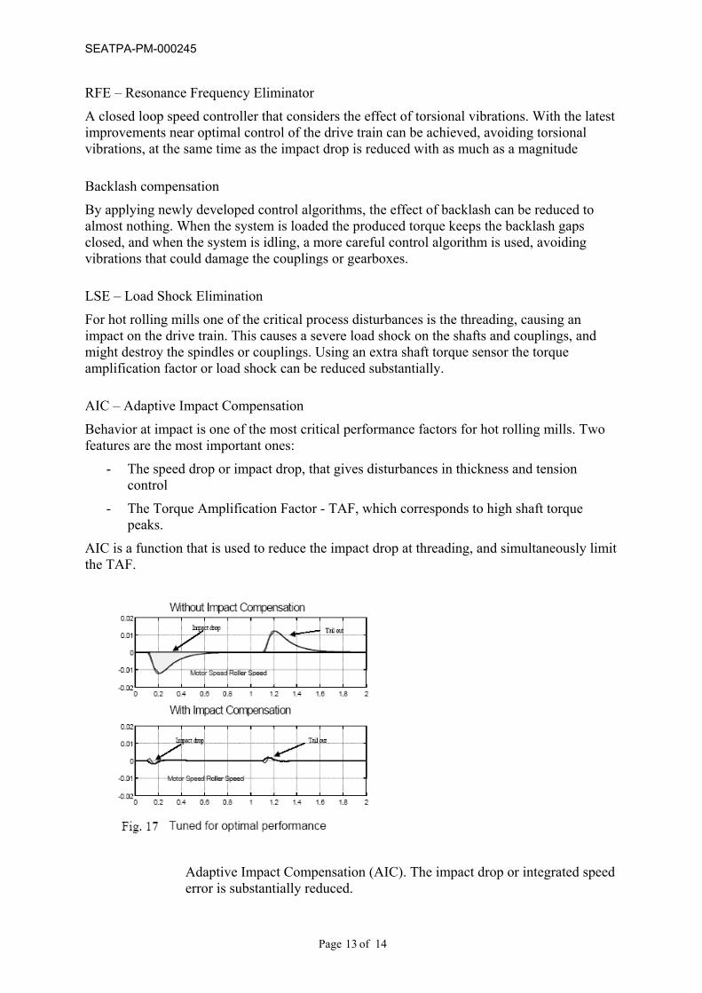
AIC – Adaptive Impact Compensation
Behavior at impact is one of the most critical performance factors for hot rolling mills. Two features are the most important ones:
- The speed drop or impact drop, that gives disturbances in thickness and tension control
- The Torque Amplification Factor - TAF, which corresponds to high shaft torque peaks.
AIC is a function that is used to reduce the impact drop at threading, and simultaneously limit the TAF.
Adaptive Impact Compensation (AIC). The impact drop or integrated speed error is substantially reduced.
Page of 14 13
SEATPA-PM-000245
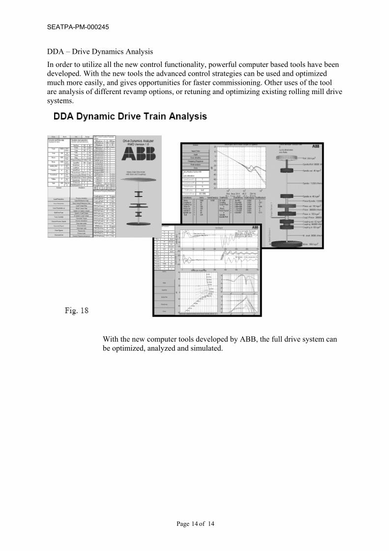
DDA – Drive Dynamics Analysis
In order to utilize all the new control functionality, powerful computer based tools have been developed. With the new tools the advanced control strategies can be used and optimized much more easily, and gives opportunities for faster commissioning. Other uses of the tool are analysis of different revamp options, or retuning and optimizing existing rolling mill drive systems.
With the new computer tools developed by ABB, the full drive system can be optimized, analyzed and simulated.
Page of 14 14