Embed Size (px)
Citation preview
7/25/2019 Abb Furse Catalogue Uk
http://slidepdf.com/reader/full/abb-furse-catalogue-uk 1/335
Earthing & lightning protection Total solution catalogue
Product Catalogue | 2015

7/25/2019 Abb Furse Catalogue Uk
http://slidepdf.com/reader/full/abb-furse-catalogue-uk 2/335
7/25/2019 Abb Furse Catalogue Uk
http://slidepdf.com/reader/full/abb-furse-catalogue-uk 3/335
1
Total Solution to Earthing & Lightning Protection | 9AKK106354A3360 1
11
5
9
13
3
7
11
15
17
2
6
10
14
4
8
12
16
18
Brand introduction
Introduction to lightning protection
Conductors
Air termination
Conductor network
Introduction to earthing
Earth electrodes
Earth bonds & clamps
FurseWELD
Introduction to electronic systems protection
Mains power protection
Data & signal protection
Telecoms & computer line protection
Specific systems protection
Protector accessories
Technical reference
Index
Chapter 18
Earthing & lightning protection Total solution catalogue

7/25/2019 Abb Furse Catalogue Uk
http://slidepdf.com/reader/full/abb-furse-catalogue-uk 4/335
7/25/2019 Abb Furse Catalogue Uk
http://slidepdf.com/reader/full/abb-furse-catalogue-uk 5/335
1
Total Solution to Earthing & Lightning Protection | 9AKK106354A3360 1/1
Introduction
Furse overview - Our reach & expertise 1/2Earthing & lightning protection - A real & significant threat 1/3
External lightning protection 1/4
Electronic systems protection 1/5
The Furse Total Solution approach 1/6
Technical advice, support & design services 1/8
Seminars & product training 1/9
Technical guides & sof tware 1/10
Project references - where we make a difference 1/11
Key markets - World leading solution to earthing & lightning protection 1/12
Introduction
7/25/2019 Abb Furse Catalogue Uk
http://slidepdf.com/reader/full/abb-furse-catalogue-uk 6/335
1/2 Total Solution to Earthing & Lightning Protection | 9AKK106354A3360
Furse overviewOur reach & expertise
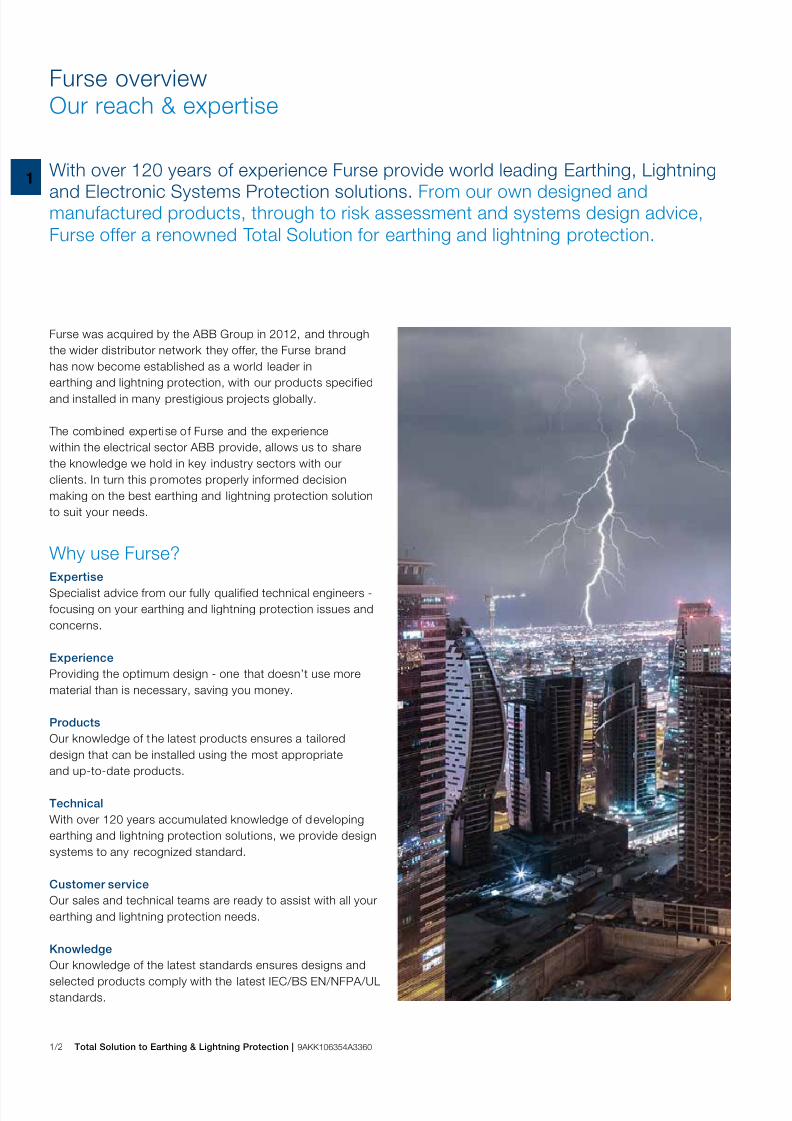
With over 120 years of experience Furse provide world leading Earthing, Lightning
and Electronic Systems Protection solutions. From our own designed andmanufactured products, through to risk assessment and systems design advice,
Furse offer a renowned Total Solution for earthing and lightning protection.
Furse was acquired by the ABB Group in 2012, and through
the wider distributor network they offer, the Furse brand
has now become established as a world leader in
earthing and lightning protection, with our products specifiedand installed in many prestigious projects globally.
The combined expertise of Furse and the experience
within the electrical sector ABB provide, allows us to share
the knowledge we hold in key industry sectors with our
clients. In turn this promotes properly informed decision
making on the best earthing and lightning protection solution
to suit your needs.
ExpertiseSpecialist advice from our fully qualified technical engineers -
focusing on your earthing and lightning protection issues and
concerns.
Experience
Providing the optimum design - one that doesn’t use more
material than is necessary, saving you money.
Products
Our knowledge of the latest products ensures a tailored
design that can be installed using the most appropriate
and up-to-date products.
Technical
With over 120 years accumulated knowledge of developing
earthing and lightning protection solutions, we provide design
systems to any recognized standard.
Customer service
Our sales and technical teams are ready to assist with all your
earthing and lightning protection needs.
Knowledge
Our knowledge of the latest standards ensures designs andselected products comply with the latest IEC/BS EN/NFPA/UL
standards.
Why use Furse?
7/25/2019 Abb Furse Catalogue Uk
http://slidepdf.com/reader/full/abb-furse-catalogue-uk 7/335
1
Total Solution to Earthing & Lightning Protection | 9AKK106354A3360 1/3
Earthing & lightning protection A real & significant threat
Lightning is one of nature’s most powerful and destructive phenomena.
Lightning strikes present a real and significant threat to life, to the structuresin which we live and work, and to the electronic systems which support us
in our daily lives.
Lightning contains awesome amounts of electrical energy.
Lightning discharges have been measured from several
thousand to over 200,000 Amps (enough to light half a million
100 Watt bulbs) and even though of a very short duration,can cause tremendous damage and destruction.
The consequences of lightning can be devastating:
– Direct lightning strikes damage structures, and create fire,
explosion and electric shock hazards.
– Indirect lightning (up to a kilometre away) creates transient
overvoltages which degrade electronic systems and
disrupt essential services.
Secondary effects of lightning
The effects of a direct strike are obvious and immediately
apparent - buildings damaged, trees blown apart, personalinjuries and even loss of life.
However, the secondary effects of lightning - the short
duration, high voltage spikes called transient overvoltages -
can, and do, cause equally catastrophic, if less visually
obvious, damage to electronic systems within structures.
The need for a Total Solution
Lightning protection throughout the world is now governed
by National and International standards which stress the need
for a comprehensive solution. Simply put, a structurallightning protection system cannot and will not protect
electronic systems from lightning currents and transient
overvoltages, that’s why we advocate a Total Solution to
earthing and lightning protection. This approach to lightning
protection is now fully endorsed by the IEC/BS EN 62305, as
well as NFPA 780 standards.
Therefore the Furse approach delivers effective li fe safety,
together with long lasting, reliable protection of a structure
and the electronic systems within. We believe the Furse Total
Solution is the best available solution for achieving effective,
dependable, long term lightning protection and earthing.
Protecting against the consequences of lightning is now of
paramount importance in any building design, our Total
Solution covers a wide range of sectors, for which we have
tailored products and services.
2 4
5 6 776 7
32 3
77 88
3211
5
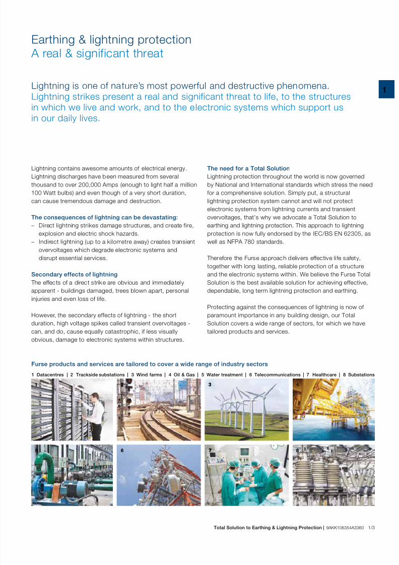
1 Datacentres | 2 Trackside substations | 3 Wind farms | 4 Oil & Gas | 5 Water treatment | 6 Telecommunications | 7 Healthcare | 8 Substations
Furse products and services are tailored to cover a wide range of industry sectors
7/25/2019 Abb Furse Catalogue Uk
http://slidepdf.com/reader/full/abb-furse-catalogue-uk 8/335
1/4 Total Solution to Earthing & Lightning Protection | 9AKK106354A3360
IntroductionExternal lightning protection
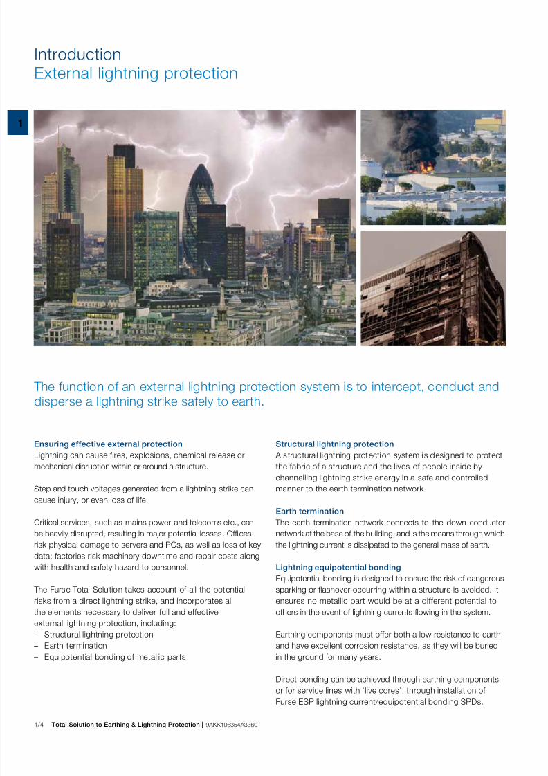
Ensuring effective external protection
Lightning can cause fires, explosions, chemical release or
mechanical disruption within or around a structure.
Step and touch voltages generated from a lightning strike can
cause injury, or even loss of life.
Critical services, such as mains power and telecoms etc., can
be heavily disrupted, resulting in major potential losses. Officesrisk physical damage to servers and PCs, as well as loss of key
data; factories risk machinery downtime and repair costs along
with health and safety hazard to personnel.
The Furse Total Solution takes account of all the potential
risks from a direct lightning strike, and incorporates all
the elements necessary to deliver full and effective
external lightning protection, including:
– Structural lightning protection
– Earth termination
– Equipotential bonding of metallic parts
Structural lightning protection
A structura l lightning protection system is designed to protect
the fabric of a structure and the lives of people inside by
channelling lightning strike energy in a safe and controlled
manner to the earth termination network.
Earth termination
The earth termination network connects to the down conductor
network at the base of the building, and is the means through whichthe lightning current is dissipated to the general mass of earth.
Lightning equipotential bonding
Equipotential bonding is designed to ensure the risk of dangerous
sparking or flashover occurring within a structure is avoided. It
ensures no metallic part would be at a different potential to
others in the event of lightning currents flowing in the system.
Earthing components must offer both a low resistance to earth
and have excellent corrosion resistance, as they will be buried
in the ground for many years.
Direct bonding can be achieved through earthing components,
or for service lines with ‘live cores’, through installation of
Furse ESP lightning current/equipotential bonding SPDs.
The function of an external lightning protection system is to intercept, conduct and
disperse a lightning strike safely to earth.
7/25/2019 Abb Furse Catalogue Uk
http://slidepdf.com/reader/full/abb-furse-catalogue-uk 9/335
1
Total Solution to Earthing & Lightning Protection | 9AKK106354A3360 1/5
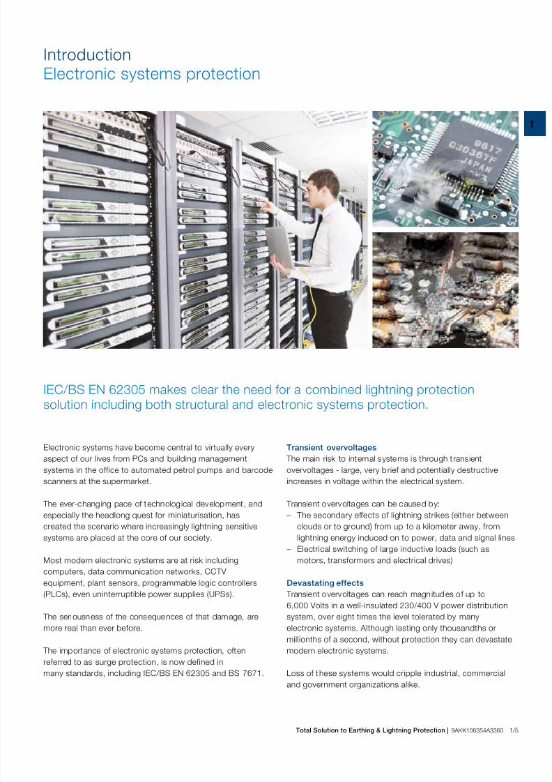
Electronic systems have become central to virtually every
aspect of our lives from PCs and building management
systems in the office to automated petrol pumps and barcode
scanners at the supermarket.
The ever-changing pace of technological development, and
especially the headlong quest for miniaturisation, has
created the scenario where increasingly lightning sensitive
systems are placed at the core of our society.
Most modern electronic systems are at risk including
computers, data communication networks, CCTV
equipment, plant sensors, programmable logic controllers
(PLCs), even uninterruptible power supplies (UPSs).
The seriousness of the consequences of that damage, are
more real than ever before.
The importance of e lectronic systems protection, often
referred to as surge protection, is now defined in
many standards, including IEC/BS EN 62305 and BS 7671.
IntroductionElectronic systems protection
Transient overvoltages
The main risk to internal systems is through t ransient
overvoltages - large, very brief and potentially destructive
increases in voltage within the electrical system.
Transient overvoltages can be caused by:
– The secondary effects of lightning strikes (either between
clouds or to ground) from up to a kilometer away, from
lightning energy induced on to power, data and signal lines – Electrical switching of large inductive loads (such as
motors, transformers and electrical drives)
Devastating effects
Transient overvoltages can reach magnitudes of up to
6,000 Volts in a well-insulated 230/400 V power distribution
system, over eight times the level tolerated by many
electronic systems. Although lasting only thousandths or
millionths of a second, without protection they can devastate
modern electronic systems.
Loss of these systems would cripple industrial, commercialand government organizations alike.
IEC/BS EN 62305 makes clear the need for a combined lightning protection
solution including both structural and electronic systems protection.
7/25/2019 Abb Furse Catalogue Uk
http://slidepdf.com/reader/full/abb-furse-catalogue-uk 10/335
1/6 Total Solution to Earthing & Lightning Protection | 9AKK106354A3360
Introduction The Furse Total Solution approach
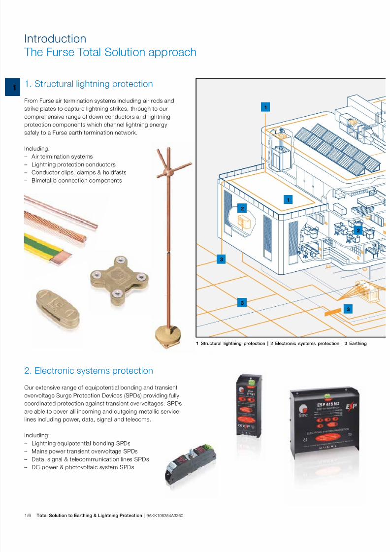
1. Structural lightning protection
From Furse air termination systems including air rods and
strike plates to capture lightning strikes, through to our
comprehensive range of down conductors and lightning
protection components which channel lightning energy
safely to a Furse earth termination network.
Including:
– Air termination systems
– Lightning protection conductors
– Conductor clips, clamps & holdfasts
– Bimetallic connection components
2. Electronic systems protection
Our extensive range of equipotential bonding and transient
overvoltage Surge Protection Devices (SPDs) providing fully
coordinated protection against transient overvoltages. SPDs
are able to cover all incoming and outgoing metallic service
lines including power, data, signal and telecoms.
Including:
– Lightning equipotential bonding SPDs
– Mains power transient overvoltage SPDs
– Data, signal & telecommunication lines SPDs
– DC power & photovoltaic system SPDs
1 Structural lightning protection | 2 Electronic systems protection | 3 Earthing
3
1
1
3
2
3
2
7/25/2019 Abb Furse Catalogue Uk
http://slidepdf.com/reader/full/abb-furse-catalogue-uk 11/335
1
Total Solution to Earthing & Lightning Protection | 9AKK106354A3360 1/7
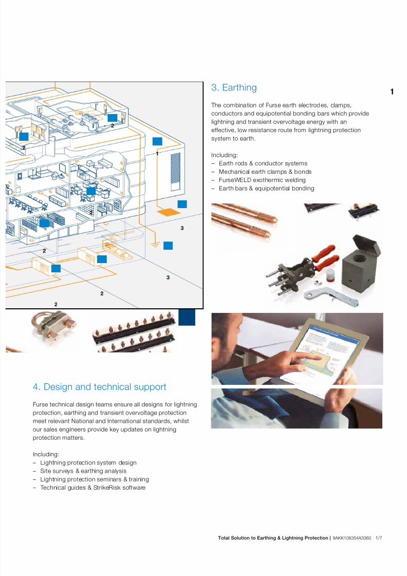
3. Earthing
The combination of Furse earth electrodes, clamps,
conductors and equipotential bonding bars which provide
lightning and transient overvoltage energy with an
effective, low resistance route from lightning protection
system to earth.
Including:
– Earth rods & conductor systems
– Mechanical earth clamps & bonds
– FurseWELD exothermic welding
– Earth bars & equipotential bonding
4. Design and technical support
Furse technical design teams ensure all designs for lightning
protection, earthing and transient overvoltage protection
meet relevant National and International standards, whilst
our sales engineers provide key updates on lightning
protection matters.
Including:
– Lightning protection system design
– Site surveys & earthing analysis
– Lightning protection seminars & training
– Technical guides & StrikeRisk software
21
3
3
2
2
2
2
2
7/25/2019 Abb Furse Catalogue Uk
http://slidepdf.com/reader/full/abb-furse-catalogue-uk 12/335
1/8 Total Solution to Earthing & Lightning Protection | 9AKK106354A3360
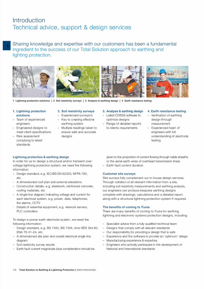
Introduction Technical advice, support & design services
Sharing knowledge and expertise with our customers has been a fundamental
ingredient to the success of our Total Solution approach to earthing andlighting protection.
1 Lightning protection solutions | 2 Soil resistivity surveys | 3 Analysis & earthing design | 4 Earth resistance testing
1. Lightning protection
solutions
– Team of experienced
engineers
– Engineered designs to
meet client specifications
– Risk assessment
complying to latest
standards
4. Earth resistance testing
– Verification of earthing
design through
measurement
– Experienced team of
engineers with full
understanding of electrode
testing
2. Soil resistivity surveys
– Experienced surveyors
– Key to creating effective
earthing system
– Multiple readings taken to
ensure safe and accurate
designs
3. Analysis & earthing design
– Latest CDEGS software to
optimize designs
– Range of detailed reports
to clients requirements
1 2 3 41 31111 22 3 442
Lightning protection & earthing design
In order for us to design a structural and/or transient over-
voltage lightning protection system, we need the following
information:
– Design standard, e.g. IEC/BS EN 62305, NFPA 780,
etc.
– A dimensioned roof plan and external elevations
– Construction details, e.g. steelwork, reinforced concrete,
roofing materials, etc
– A single line diagram indicating voltage and current for
each electrical system, e.g. power, data, telephones,fire alarms, CCTV
– Details of essential equipment, e.g. network servers,
PLC controllers
To design a power earth electrode system, we need the
following information:
– Design standard, e.g. BS 7430, BS 7354, Ansi IEEE Std 80,
ENA TS 41-24, etc.
– A dimensioned site plan and overall electrical single line
diagram
– Soil resistivity survey results
– Earth fault current magnitude (due consideration should be
given to the proportion of current flowing through cable sheaths
or the aerial earth wires of overhead transmission lines)
– Earth fault current duration
Customer site surveys
Site surveys fully complement our in-house design services.
Through collation of al l relevant information f rom a si te,
including soil resistivity measurements and earthing analysis,
our engineers can produce bespoke earthing designs
complete with drawings, calculations and a detailed report,
along with a structural lightning protection system if required.
The benefits of coming to Furse
There are many benefits of coming to Furse for earthing,
lightning and electronic systems protection designs, including:
– Specialist advice from a fully qualified technical team
– Designs that comply with all relevant standards
– Our responsibility for providing a design that is safe
– Experience and the software to provide an ‘optimum’ design
– Manufacturing experience & expertise
– Engineers who actively participate in the development of
National and International standards
7/25/2019 Abb Furse Catalogue Uk
http://slidepdf.com/reader/full/abb-furse-catalogue-uk 13/335
1
Total Solution to Earthing & Lightning Protection | 9AKK106354A3360 1/9
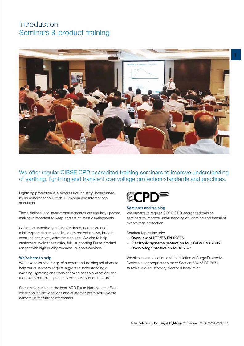
IntroductionSeminars & product training
Lightning protection is a progressive industry underpinned
by an adherence to British, European and International
standards.
These National and International standards are regularly updated
making it important to keep abreast of latest developments.
Given the complexity of the standards, confusion and
misinterpretation can easily lead to project delays, budget
overruns and costly extra time on site. We aim to helpcustomers avoid these risks, fully supporting Furse product
ranges with high quality technical support services.
We’re here to help
We have tailored a range of support and training solutions to
help our customers acquire a greater understanding of
earthing, lightning and transient overvoltage protection, and
thereby to help clarify the IEC/BS EN 62305 standards.
Seminars are held at the local ABB Furse Nottingham office,
other convenient locations and customer premises - please
contact us for further information.
Seminars and training
We undertake regular CIBSE CPD accredited training
seminars to improve understanding of lightning and transient
overvoltage protection.
Seminar topics include:
– Overview of IEC/BS EN 62305 – Electronic systems protection to IEC/BS EN 62305
– Overvoltage protection to BS 7671
We also cover selection and installation of Surge Protective
Devices as appropriate to meet Section 534 of BS 7671,
to achieve a satisfactory electrical installation.
We offer regular CIBSE CPD accredited training seminars to improve understanding
of earthing, lightning and transient overvoltage protection standards and practices.
7/25/2019 Abb Furse Catalogue Uk
http://slidepdf.com/reader/full/abb-furse-catalogue-uk 14/335
1/10 Total Solution to Earthing & Lightning Protection | 9AKK106354A3360
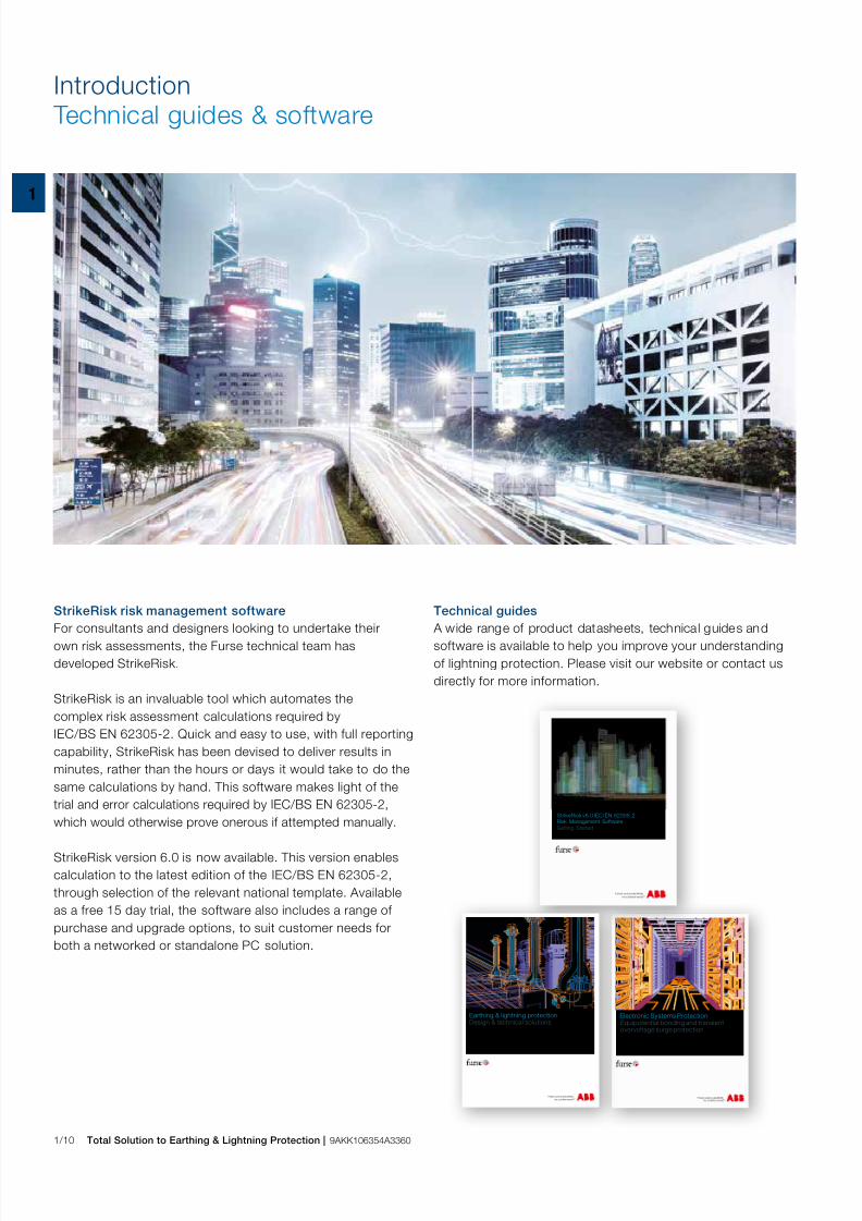
Introduction Technical guides & software
Technical guides
A wide range of product datasheets, technical guides andsoftware is available to help you improve your understanding
of lightning protection. Please visit our website or contact us
directly for more information.
StrikeRisk risk management software
For consultants and designers looking to undertake theirown risk assessments, the Furse technical team has
developed StrikeRisk.
StrikeRisk is an invaluable tool which automates the
complex risk assessment calculations required by
IEC/BS EN 62305-2. Quick and easy to use, with full reporting
capability, StrikeRisk has been devised to deliver results in
minutes, rather than the hours or days it would take to do the
same calculations by hand. This software makes light of the
trial and error calculations required by IEC/BS EN 62305-2,
which would otherwise prove onerous if attempted manually.
StrikeRisk version 6.0 is now available. This version enables
calculation to the latest edition of the IEC/BS EN 62305-2,
through selection of the relevant national template. Available
as a free 15 day trial, the software also includes a range of
purchase and upgrade options, to suit customer needs for
both a networked or standalone PC solution.
Electronic Systems ProtectionEquipotential bonding and transientovervoltage surge protection
StrikeRisk v6.0 IEC/EN 62305-2Risk Management Software
Getting Started
Earthing & lightning protection Design & technical solutions

7/25/2019 Abb Furse Catalogue Uk
http://slidepdf.com/reader/full/abb-furse-catalogue-uk 15/335
1
Total Solution to Earthing & Lightning Protection | 9AKK106354A3360 1/11
Project referencesWhere we make a difference
Our Total Solution approach, which delivers innovative, high quality products
supported by intelligent, concise technical support, makes Furse the brand of choice
for many projects, in many markets, worldwide.
Oil & gas / Petrochemical
– Oil Fields in Toha, China – Pertamenia Gas / Petrol Depot,
Indonesia
– Asab Full Field Development, UAE
– Dorra Gas Field Development,
Saudi Arabia
– Jubail Chevron Phill ips (JCP)
– Petrochemical Plant, Saudi Arabia
Utilities
– Waste Water Treatment Plant,
Shoiba, Saudi Arabia
– JAFZA Desalination Plant, UAE – Hammas Power Station, Algeria
– Shuwaikh Desalination Plant, Kuwait
– Tianwan Nuclear Power Plant, China
– Mombassa Substation, Kenya
– Kapichira Hydo-Power Station, Malawi
Rail & infrastructure
– Bahrain Int’l Airport Expansion
– Shanghai Metro, China
– Kowloon Rail Link, Hong Kong
– New Terminal, Seeb Airport, Oman
– Circle Line, Mass Rapid TransitSystem, Singapore
– Channel Tunnel Rail Link, UK
High tech & industrial
– Taiwan Semiconductor ManufacturingCorporation, China
– China Telecom
– Intel Plant, High Tech Kulim, Malaysia
– Kuala Lumpur Telecoms Tower,
Malaysia
– Seagate Semiconductor Plant,
Singapore
– Alexandra Technopark, Singapore
– Motorola Factories, Singapore
– Najran Cement Factory, Saudi Arabia
– Merck, Sharp & Dohme
Pharmaceutical Plant, Singapore – Alfred McAlpine Quarry Products, UK
Commercial construction
– Bahrain Financial Harbour
– Emirates Towers, Bahrain
– Petronas Twin Towers, Malaysia
– Oman Arab Bank, Oman
– Kuala Lumpur Stock Exchange, Malaysia
– Graha Energy Building, Indonesia
– Canary Wharf, London, UK
– Highland Distilleries Co plc, UK
– Barwa Financial District, Qatar – London Stock Exchange
– Royal Bank of Scotland
Sports & recreation
– MGM Grand Hotel & Complex,Macau, China
– Bahrain Opera House
– Azizia Mall, Kuwait
– Disneyland Hong Kong
– Sebang International Formula One
Circuit, Malaysia
– Manchester United Training
Ground, UK
– Grand Plaza Hotel, Singapore
– Dubai Sports City Complex, UAE
Government & public sector – Royal College of Surgeons,
Muharraq, Bahrain
– Ministry of Foreign Affairs, Brunei
– Singapore Embassy, China
– Prime Minister’s Office, Putrajaya,
Malaysia
– University Institute of Technology,
Ijok-Selangor, Malaysia
– Ministry of Finance Administrative
Building, Malaysia
– Mater Dei General Hospital, Malta
– International Maritime College, Oman – Al Jaber Hospital, Kuwait
– British Library, London, UK
1 Bank of England, UK | 2 Channel Tunnel Rail Link, UK | 3 Canary Wharf, London, UK | 4 Circle Line, Mass Rapid Transit System, Singapore
5 Heathrow Airport, London, UK | 6 Kuala Lumpur Stock Exchange, Malaysia | 7 Manchester United Training Ground, UK | 8 Financial Towers, Bahrain
4
6 7 8
321
5 77
7/25/2019 Abb Furse Catalogue Uk
http://slidepdf.com/reader/full/abb-furse-catalogue-uk 16/335
1/12 Total Solution to Earthing & Lightning Protection | 9AKK106354A3360
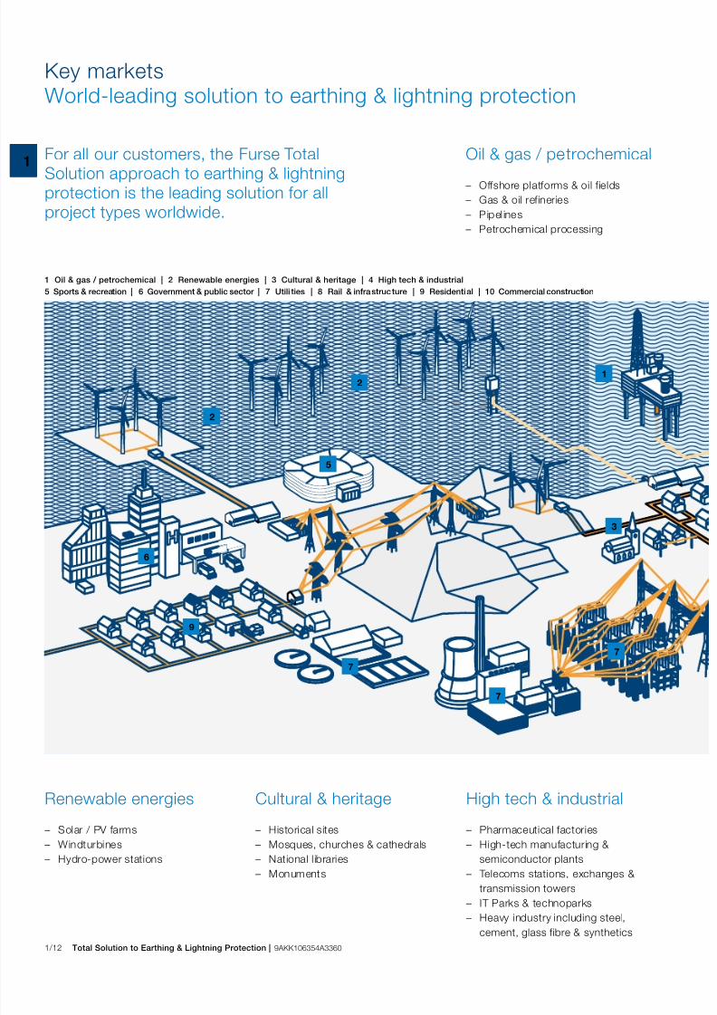
Key marketsWorld-leading solution to earthing & lightning protection
1 Oil & gas / petrochemical | 2 Renewable energies | 3 Cultural & heritage | 4 High tech & industrial
5 Sports & recreation | 6 Government & public sector | 7 Utili ties | 8 Rail & infrastructure | 9 Residential | 10 Commercial construction
21
6
7
7
Oil & gas / petrochemical
– Offshore platforms & oil fields
– Gas & oil ref ineries
– Pipel ines
– Petrochemical processing
For all our customers, the Furse Total
Solution approach to earthing & lightningprotection is the leading solution for all
project types worldwide.
Renewable energies
– Solar / PV farms
– Windturbines
– Hydro-power stations
High tech & industrial
– Pharmaceutical factories
– High-tech manufacturing &
semiconductor plants
– Telecoms stations, exchanges &transmission towers
– IT Parks & technoparks
– Heavy industry including steel,
cement, glass fibre & synthetics
Cultural & heritage
– Historical sites
– Mosques, churches & cathedrals
– National l ibraries
– Monuments
5
3
2
7
9
7/25/2019 Abb Furse Catalogue Uk
http://slidepdf.com/reader/full/abb-furse-catalogue-uk 17/335
1
Total Solution to Earthing & Lightning Protection | 9AKK106354A3360 1/13
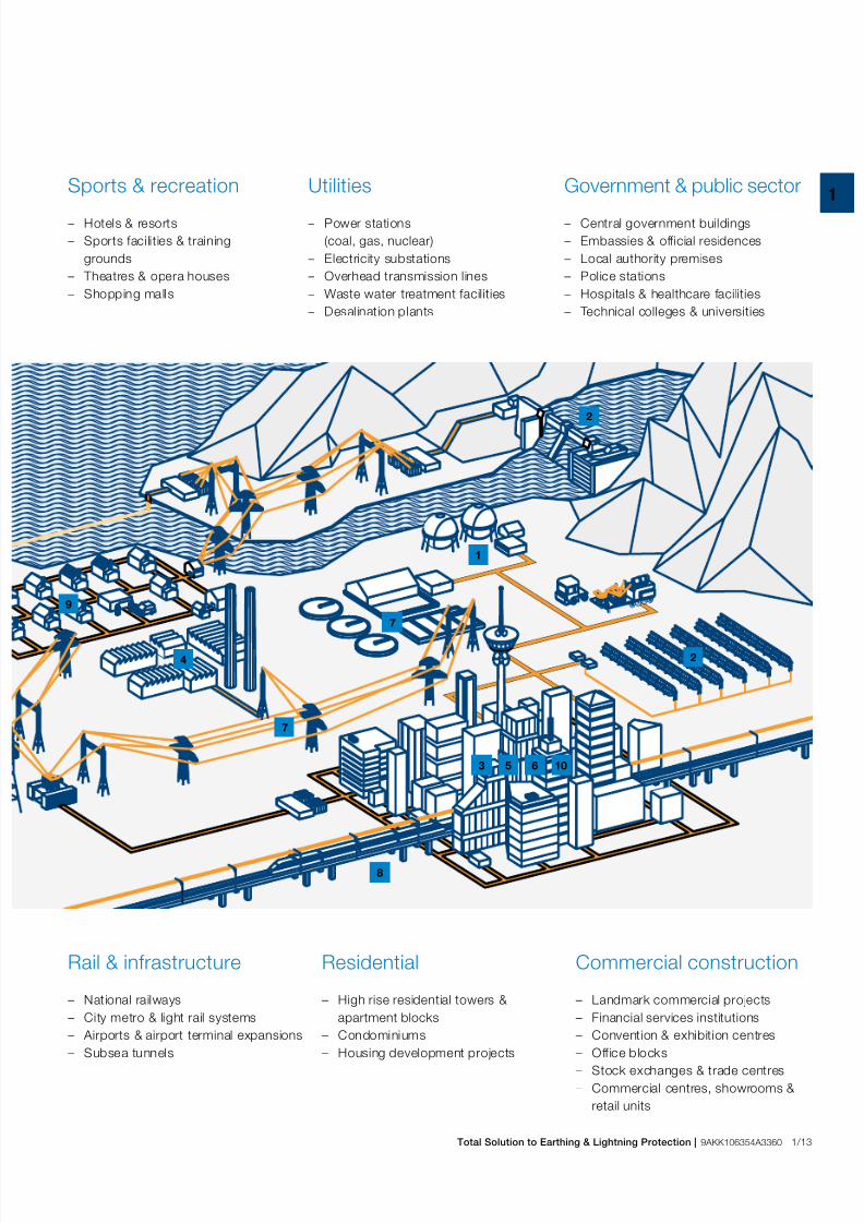
Markets covered:
6
7
8
2
2
1
Sports & recreation
– Hotels & resorts
– Sports facilities & training
grounds
– Theatres & opera houses
– Shopping malls
Utilities
– Power stations
(coal, gas, nuclear)
– Electricity substations
– Overhead transmission lines
– Waste water treatment facilities
– Desalination plants
Government & public sector
– Central government buildings
– Embassies & official residences
– Local authority premises
– Police stations
– Hospitals & healthcare facilities
– Technical colleges & universities
Rail & infrastructure
– National railways
– City metro & light rail systems
– Airports & airport terminal expansions
– Subsea tunnels
Commercial construction
– Landmark commercial projects
– Financial services institutions
– Convention & exhibition centres
– Off ice blocks – Stock exchanges & trade centres
– Commercial centres, showrooms &
retail units
Residential
– High rise residential towers &
apartment blocks
– Condominiums
– Housing development projects
4
9
5 10
7
3

7/25/2019 Abb Furse Catalogue Uk
http://slidepdf.com/reader/full/abb-furse-catalogue-uk 18/335
2/0 Total Solution to Earthing & Lightning Protection | 9AKK106354A3360

7/25/2019 Abb Furse Catalogue Uk
http://slidepdf.com/reader/full/abb-furse-catalogue-uk 19/335
Total Solution to Earthing & Lightning Protection | 9AKK106354A3360 2/1
2
Lightning Protection
Introduction to lightning protection 2/2Product selection guide 2/4
Introduction to lightning protection

7/25/2019 Abb Furse Catalogue Uk
http://slidepdf.com/reader/full/abb-furse-catalogue-uk 20/335
2/2 Total Solution to Earthing & Lightning Protection | 9AKK106354A3360
Introduction to lightning protection
The decision about which type to use is of ten based more
on country-specific historical preferences or aesthetic
considerations than the superiority of one type over another.
High quality Furse conductors, plus appropriate fittings,
are available for all three systems.
Flat tape conductor system
Flat tape conductors are easy to install, with no need tostraighten for a neat finish. Available in copper or aluminium,
flat tape can be installed bare or with a choice of PVC
coverings, to enable the tape to blend with modern
building fabrics.
Tinned copper tape is also avai lable for applications that
require additional protection measures, and copper braid is
available for use where flexibility is necessary, e.g. on moving
installations like gates or doors.
Furse copper tape is approved to BS EN 13601, whilst Furse
aluminium tape is manufactured to BS EN 755-5.
When designing a structural lightning protection system using the Faraday Cage
principle advocated by IEC/BS EN 62305, it is possible to use one or more typesof conductor, such as flat tape, solid circular or cable and wire (stranded).

7/25/2019 Abb Furse Catalogue Uk
http://slidepdf.com/reader/full/abb-furse-catalogue-uk 21/335
Total Solution to Earthing & Lightning Protection | 9AKK106354A3360 2/3
2
Solid circular conductor system
Solid circular conductors can be used in applications whereaesthetic considerations are important.
The 8 mm diameter solid ci rcular range is less conspicuous
than the flat tape system, and lends itself much better to
being concealed. Available in copper or aluminium, solid
circular conductors can also have PVC coverings.
A coil of circular conductor can be quickly installed, being
easy to bend in any plane, and only needing a straightening
tool to give a very neat finish.
Furse copper solid circular conductor is manufactured toBS EN 13601, whilst Furse aluminium solid circular conductor
is manufactured to BS EN 755-5.
Stranded conductor system
The Furse range of soft drawn stranded conductors is
available in copper, either bare or PVC insulated, and complies
with the US standard NFPA 780.
Furse soft drawn stranded conductor is manufactured to
BS EN 60228, whilst our PVC insulated stranded conductoris manufactured to BS EN 50525.
The Furse range of conductors is complemented by a
complete range of fittings, including clips, clamps,
holdfasts and bimetallic connectors.
Fittings are designed to conform to the IEC/BS EN 62561
series of product standards for lightning protection
components, with those installed with the most common
conductor types suitably tested.

7/25/2019 Abb Furse Catalogue Uk
http://slidepdf.com/reader/full/abb-furse-catalogue-uk 22/335
2/4 Total Solution to Earthing & Lightning Protection | 9AKK106354A3360
Introduction to lightning protectionProduct selection guide
Conductors
The firs t choice faced by the designer of a structural l ightning
protection system is the type of conductor system to be used:
– Choose the material required, i.e. copper or aluminium
– Choose the type of conductor required, i.e. flat tape, solid
circular or stranded
1. Conductor network
The conductor network is the means ofintercepting/carrying the current of a
lightning strike safely to the earth
termination network. Use the guidelines
of IEC/BS EN 62305-1 & -3 for the
correct placement of conductors.
2. Fixings
Select the correct system of fixings for
each part of the conductor system.
Fixings are available for a wide range of
modern construction materials,
e.g. brick, stone, plastic and metal.
Air termination network
The air terminat ion network is the point of connection for a
lightning strike. It typically consists of a meshed conductor
arrangement covering the roof of the structure. The mesh size
is determined by Lightning Protection Level - LPL.
3. Air terminals
Use air terminals in the form of vertical air
rods for the protection of prominentroof top features or equipment. Use strike
pads to connect and thus expose
concealed conductors.
Air termination network
4. Air rod bases
Choose the correct air rod base. This
will ensure that the vertical air rods
are both solidly fixed to the fabric of the
structure and have a low resistance
connection to the conductor network.
5. Interconnection components
Crossover clamps have been specially
designed for use where conductors cross
as part of a roof network.
Main aspects and individual components of an external lightning protection system
5
8
12
1
8
8
8
12
11
1
2
3
4
5
Product selection guide - Lightning protection
No. Type Section / Page No.1. Conductors 3/4
2. Conductor fixings 5/2
3. Air terminals 4/3
4. Air rod bases 4/4, 4/11
5. Conductor jointing clamps 5/16
6. Test clamps 5/19
7. Crossover conductor clamp 5/16
8. Ear th elect rodes 7/3, 7/10
9. Earth rod clamps 8/2
10. Earth inspection pits 7/9
11. Bonds 8/10
12. Lightning current or equipotent ial bonding SPDs 11/3

7/25/2019 Abb Furse Catalogue Uk
http://slidepdf.com/reader/full/abb-furse-catalogue-uk 23/335
Total Solution to Earthing & Lightning Protection | 9AKK106354A3360 2/5
2
6
Down conductor network
6. Conductor jointing clamps
Select a component for the
interconnection of multiple conductors or
for changes of direction. Jointing clamps
will ensure a low resistance, corrosion
resistant connection between air
termination and down conductors.
7. Test clamps
In order to allow periodic disconnection
and testing of the earth termination
network, select a test clamp to be placedwithin the run of each down conductor.
Earth termination network
The means of dissipating the current to the general
mass of earth.
8. Earth electrodes
Choose an earth electrode to suit the
system design i.e. Type A, Type B or
foundation electrode. Electrodes can be
constructed individually from earth
rods, earth plates, flat tape, stranded
cable or any combination of these.
9. Earth rod clampsSelect a high copper content alloy earth
rod clamp for the connection of the
earthing conductor to the earth rod. In
this below ground application, the clamp
must ensure a good electrical contact
and resist corrosion throughout the
lifetime of the installation.
10. Earth inspection pits
Select an earth inspection pit to protect
the earth electrode connections. High
strength pits are available in plasticand concrete.
Equipotential bonding
Bonding is the most commonly employed method of
avoiding the damaging effects of side flashing. All continuous
metalwork should be considered for bonding. All metallic
services, e.g. cable armouring, gas, water or steam
piping, entering the building should also be bonded as
directly as possible to the earth termination network.
11. Bonds to metalwork
Select the correct type of metalwork
bond for the application, i.e. a flat
column face, a circular rainwater pipe or
a ribbed reinforcing bar.
12. Equipotential bonding SPDs
Designed to prevent dangerous sparking
caused by flashover, lightning current or
equipotential bonding SPDs must befitted to all metallic service lines with ‘live
cores’ entering or leaving the structure.
This i llust ration is designed to demonstrate the main aspects and
individual components of an external lightning protection system. It is not
intended to represent an actual scheme conforming to a particular
code of practice. The drawing is not to scale.
1
2
3
4
6
7
9
10
111
8
8
2
8
5
7
8
9
10
11
12

7/25/2019 Abb Furse Catalogue Uk
http://slidepdf.com/reader/full/abb-furse-catalogue-uk 24/335
3/0 Total Solution to Earthing & Lightning Protection | 9AKK106354A3360

7/25/2019 Abb Furse Catalogue Uk
http://slidepdf.com/reader/full/abb-furse-catalogue-uk 25/335
Total Solution to Earthing & Lightning Protection | 9AKK106354A3360 3/1
3
Conductors
Conductors
Introduction 3/2
Bare conductors
Bare copper tape 3/4
Bare aluminium tape 3/5
Bare solid circular 3/5
Bare stranded & tinned conductors
Bare stranded copper cable 3/6
Tinned copper tape 3/6
Bimetallic cable & hard drawn bar
Bimetallic cable 3/7Hard drawn copper bar 3/7
Flexible braid
Flexible flat copper braid 3/8
Flexible circular copper braid 3/9
PVC covered conductors
PVC covered copper tape 3/10
PVC covered copper solid circular 3/10
PVC covered aluminium tape 3/11
PVC covered aluminium solid circular 3/11
Green & yellow PVC insulated copper tape 3/12
Green & yellow PVC insulated stranded copper cable 3/12
LSOH covered conductors
LSOH covered copper tape 3/13
Lead covered conductors
Lead covered copper tape 3/13
Conductor guards
PVC protective down conductor guard 3/14
Anti-vandal down conductor guard 3/14

7/25/2019 Abb Furse Catalogue Uk
http://slidepdf.com/reader/full/abb-furse-catalogue-uk 26/335
3/2 Total Solution to Earthing & Lightning Protection | 9AKK106354A3360
ConductorsIntroduction
Selection of the correct conductor type for the installation is
highly important, and is likely to be the initial consideration
of a lightning protection or earthing system designer.
A comprehens ive range of Furse copper and aluminium
conductors is available in each of the main globally
recognized standard formats, i.e. flat tape, solid circular and
stranded (note, copper stranded only). Additionally each
format is available in a variety of conductor sizes, to meet
differing lightning protection and earthing requirements.
Specification will depend on whether the application is for an
above ground structural lightning protection system, or
a below ground earthing installation.
By far the largest and most important component of any structural lightning
protection or earthing system is the actual conductor.
Conductors for structural lightning protection systems
Furse lightning protection conductors are available in copper
and aluminium. Copper can be supplied bare, tinned, PVC,
LSOH and lead covered. It is used for most installations due
to its high conductivity, anticorrosive properties, and its
flexibility for use in air, in earth and in concrete. Aluminium can
be supplied bare or with PVC coating.
The fol lowing sizes are suitable for the majority of aboveground lightning protection systems:
– Flat tape conductor
25 x 3 mm bare tape, or 25 x 3 mm PVC covered tape
– Solid circular conductor
8 mm diameter bare or PVC covered solid
circular conductor
– Stranded conductor
70 mm2 bare or PVC covered stranded conductor
Conductor colour chart
The choice of a lightning protection conductor is usually
governed by its aesthetic impact on the structure to beprotected. For many people the term lightning protection
conductor conjures up an image of a discoloured copper strip
running down the spire of a church. This would clearly
be unacceptable to the owner/architect of a modern
structure.
In order to reduce the impact of an external system Furse
offer a range of UV stabilized PVC covered tapes and
solid circular conductors in colours chosen to match most
common building materials.
Standard PVC colours are shown in the chart above,with special colours available to order.
Conductor colour chart
Colour Standard
Black 18B29*
Green BS 6746C
Grey 00A07*
Stone 08B23*
White 10B15*
Brown 06C39**PVC colours to BS 5252

7/25/2019 Abb Furse Catalogue Uk
http://slidepdf.com/reader/full/abb-furse-catalogue-uk 27/335
Total Solution to Earthing & Lightning Protection | 9AKK106354A3360 3/3
3
Furse earthing conductors form an integral part of the single
earthing arrangement for a structure, whether they providethe means of connection to the final earth electrode (earth rod
or plate), or whether they comprise the earth electrode itself
(through an earth grid or ring earth arrangement).
An earth conductor must be capable of carry ing the maximum
expected earth fault current and leakage current likely to
occur at a structure. The size or minimum cross-sectional
area of the conductor must therefore be gauged in
accordance with these criteria.
A good earth conductor must also:
– Be able to withstand mechanical damage – Be compatible with the material of the earth electrode
– Resist the corrosive effect of local soil conditions
Furse conductors effectively meet these requirements and are
available in a range of sizes to meet differing current ratings
(see table left). Copper conductor is recommended as,
following BS 7430, aluminium should not be installed in
contact with soil, nor in damp areas, and it should not be
used to make the final connection to an earth electrode.
Conductors for earthing systems
For below ground earthing applications we offer a large rangeof bare copper tape, solid circular and stranded conductors
thus offering the designer of the system the correctly rated
conductor without the need to oversize.
Conductor Size C.S.A.
(mm) (mm2) kA for 1 Sec kA for 3 Sec
12.5 x 1.5 18.75 3.3 1.9
12.5 x 3 37.5 6.6 3.8
20 x 1.5 30 5.3 3.0
20 x 3 60 10.6 6.1
25 x 1.5 37.5 6.6 3.8
25 x 3 75 13.2 7.625 x 2 50 8.8 5.1
25 x 4 100 17.6 10.2
25 x 6 150 26.4 15.2
30 x 2 60 10.6 6.1
30 x 3 90 15.8 9.1
30 x 4 120 21.1 12.2
30 x 5 150 26.4 15.2
31 x 3 93 16.4 9.5
31.5 x 4 126 22.2 12.8
31 x 6 186 32.7 18.9
38 x 3 114 20.1 11.6
38 x 5 190 33.4 19.338 x 6 228 40.1 23.2
40 x 3 120 21.1 12.2
40 x 4 160 28.2 16.3
40 x 5 200 35.2 20.3
40 x 6 240 42.2 24.4
40 x 6.3 252 44.4 25.6
50 x 3 150 26.4 15.2
50 x 4 200 35.2 20.3
50 x 5 250 44.0 25.4
50 x 6 300 52.8 30.5
50 x 6.3 315 55.4 32.0
50 x 7 350 61.6 35.5
50 x 8 400 70.4 40.6
50 x 10 500 88 50.8
60 x 10 600 105.6 61
80 x 6 480 84.4 48.8
100 x 6 600 105.6 61
These conductor ratings are based upon the recommendations of BS 7430 with an
initial conductor temperature of 30°C and a maximum temperature of 250°C
3

7/25/2019 Abb Furse Catalogue Uk
http://slidepdf.com/reader/full/abb-furse-catalogue-uk 28/335
3/4 Total Solution to Earthing & Lightning Protection | 9AKK106354A3360
ConductorsBare conductors
Bare copper tape
Conductor size Standard Weight
(X x Y) coil size
per metre
Part no. (mm) (m) (kg)
TC005 12.5 x 1.5 100 0.17
TC010 12.5 x 3 100 0.33
TC015 20 x 1.5 100 0.27
TC020 20 x 3 50 0.53
TC020/ 100 20 x 3 100 0.53
TC025 25 x 1.5 100 0.33
TC026 25 x 2 50 0.49
TC030 25 x 3 25 0.67
TC030/50 25 x 3 50 0.67
TC030 -UL 1” x1
⁄ 8” 25 0.67TC035 25 x 4 50 0.89
TC040 25 x 6 40 1.33
TC040 -UL 1” x 1 ⁄ 4” 40 1.33
TC039 30 x 2 50 0.53
TC042 30 x 3 50 0.80
TC044 30 x 4 40 1.07
TC043 30 x 5 40 1.33
TC045 31 x 3 50 0.83
TC048 31.5 x 4 40 1.13
TC050 31 x 6 30 1.65
TC055 38 x 3 50 1.01
TC060-FU 38 x 5 30 1.69TC065 38 x 6 25 2.02
TC067 40 x 3 40 1.06
TC066 40 x 4 30 1.42
TC071 40 x 5 25 1.78
TC068 40 x 6 25 2.16
TC069 40 x 6.3 25 2.24
TC070 50 x 3 40 1.33
TC075 50 x 4 30 1.78
TC078 50 x 5 20 2.22
TC080 50 x 6 20 2.68
TC082 50 x 6.3 20 2.80
TC090 50 x 7 320 3.08
TC092 50 x 8 20 3.56
TC094 50 x 10 10 4.44
TC096 60 x 10 10 5.32
TC098 80 x 6 10 4.32
TC099 100 x 6 10 5.36
– All bare copper tape sold in fu ll coi l l engt hs only
– High conductivity annealed copper tape
Standards
UL96 (TC030-UL, TC040-UL,TC080)
BS EN 13601
IEC/BS EN 62561-2

7/25/2019 Abb Furse Catalogue Uk
http://slidepdf.com/reader/full/abb-furse-catalogue-uk 29/335
Total Solution to Earthing & Lightning Protection | 9AKK106354A3360 3/5
3
Bare aluminium tape
Conductor size Standard Weight
(X x Y) coil size per metre
Part no. (mm) (m) (kg)
TA005 12.5 x 1.5 50 0.05
TA020 20 x 3 50 0.17
TA030 25 x 3 50 0.21
TA042 30 x 3 50 0.25
TA040 25 x 6 50 0.42
TA068 40 x 6 50 0.67
TA080 50 x 6 50 0.85
– All bare alumin ium tape so ld in f ull coi l l eng ths only
ConductorsBare conductors
Bare solid circular
Cross-sectional
Standard
Weight
Conductor
Diameter (A)
area
coil size per metre
Part no. mater ial (mm) (mm2) (m) (kg)
Copper conductor
CD035 Copper Ø 8 50.27 50 0.44
Aluminium conductor
CD080 Aluminium Ø 8 50.27 50 0.12
Tinned copper conductor
CD235 Copper Ø 8 50.27 50 0.44
– All sol id c ircula r conductor sold in full coi l le ngth s on ly
A
Standards
Standards
BS EN 755-5
IEC/BS EN 62561-2
BS EN 13601 (copper)
BS EN 755-5 (aluminium)

7/25/2019 Abb Furse Catalogue Uk
http://slidepdf.com/reader/full/abb-furse-catalogue-uk 30/335
3/6 Total Solution to Earthing & Lightning Protection | 9AKK106354A3360
ConductorsBare stranded & tinned conductors
Bare stranded copper cable
Cross-sectional Stranding Nominal Weight
area no. / diameter (A) per metre
Part no. (mm2) mm ø (mm) (kg)
Soft drawn stranded copper cable
CB00 6 6 7/1.04 Ø 3.12 0.05
CB016 16 7/1.70 Ø 5.10 0.15
CB025 25 7/2.14 Ø 6.42 0.23
CB035 35 7/2.52 Ø 7.56 0.32
CB050 -FU 50 19/1.78 Ø 8.90 0.43
CB070 70 19/2.14 Ø 10.70 0.62
CB095 95 19/2.52 Ø 12.60 0.86
CB120 120 37/2.03 Ø 14.21 1.09
CB150-FU 150 37/2.25 Ø 15.75 1.33CB185 185 37/2.52 Ø 17.64 1.67
CB240 240 61/2.25 Ø 20.25 2.20
CB300-FU 300 61/2.52 Ø 22.68 2.76
CB400-FU 400 61/2.85 Ø 25.65 3.53
Tinned soft drawn stranded copper cable
CB070-T* 70 19/2.14 Ø 10.70 0.62
Hard drawn stranded copper cable
CB071* 70 7/3.55 Ø 10.70 0.64
– *Additional sizes available on request
Tinned copper tape
Conductor size Standard Weight
(X x Y) coil size per metre
Part no. (mm) (m) (kg)
TC220 20 x 3 50 0.53
TC225 -FU 12.5 x 1.5 100 0.17
TC226 25 x 2 50 0.49
TC230 25 x 3 50 0.67
TC230 -UL 1” x 1 ⁄ 8” 50 0.67
TC239 30 x 2 50 0.53
TC240 25 x 6 40 1.33
TC245 31 x 3 50 0.83
TC260 38 x 5 30 1.69
TC266 40 x 4 30 1.42
TC267 40 x 3 40 1.06
TC280 50 x 6 20 2.68
– All tinned copper tape sold in full coil l engths only
– High conductivity annealed tinned copper tape
Standards
A
Standards
UL96 (TC230-UL)
BS EN 60228 (soft drawn)
BS EN 7884 (hard drawn)
BS EN 13601
IEC/BS EN 62561-2

7/25/2019 Abb Furse Catalogue Uk
http://slidepdf.com/reader/full/abb-furse-catalogue-uk 31/335
Total Solution to Earthing & Lightning Protection | 9AKK106354A3360 3/7
3
Bimetallic cable
Cross-sectional Nominal Weight area diameter Stranding per metre
Part no. AWG (mm2) (mm) no. / AWG (kg)
BC001 1/0 50 Ø 9.96 3/5 0.41
BC002 1 40 Ø 8.86 3/6 0.33
BC003 2 35 Ø 7.90 3/ 7 0.26
BC004 3 25 Ø 7.04 3/8 0.21
BC005 4 20 Ø 6.27 3/9 0.16
BC006 5 16 Ø 5.59 3 /10 0.13
BC007 6 10 Ø 4.42 3 /12 0.08
BC008 300 150 Ø 15.6 7/4 1.22
BC009 4/0 120 Ø 13.9 7/5 0.97
BC010 3/0 95 Ø 12.3 7/6 0.77BC011 2/0 70 Ø 11.00 7/7 0.61
BC012 1/0 50 Ø 9.78 7/8 0.48
BC013 1 40 Ø 8.71 7/9 0.38
BC014 2 35 Ø 7.77 7/10 0.30
– 40% conductivity supplied as standard. Other sizes also available. Contact us for details
ConductorsBimetallic cable & hard drawn bar
Hard drawn copper bar
Overall nominal Approximate Weight
size (X x Y) length per metre
Part no. (mm) (m) (kg)
Bare hard drawn bar
BA205 25 x 3 3 0.67
BA210 25 x 6 4 1.33
BA225 38 x 6 4 2.03
BA230 50 x 6 3 2.67
BA235 50 x 10 4 4.45
BA240 75 x 6 4 4.00
BA250-FU 100 x 6 4 5.38
Tinned hard drawn bar
BA20 6 25 x 3 3 0.67
BA211 25 x 6 4 1.33
BA226 38 x 6 4 2.03
BA231 50 x 6 3 2.67
BA236 50 x 10 4 4.45
BA241 75 x 6 4 4.00
BA251-FU 100 x 6 4 5.38
– Other sizes available on request
Standards
B228
Standards
BS EN 12163

7/25/2019 Abb Furse Catalogue Uk
http://slidepdf.com/reader/full/abb-furse-catalogue-uk 32/335
3/8 Total Solution to Earthing & Lightning Protection | 9AKK106354A3360
ConductorsFlexible braid
Flexible flat copper braid
Overall nominal Cross-sectional Weight size (X x Y) area per metre
Part no. (mm) (mm2) (kg)
Bare flat braid
BD020 12 x 1 6 0.06
BD025 15 x 1.5 10 0.10
BD026 19 x 2.5 16 0.16
BD028 25 x 3 25 0.25
BD030 25 x 3.5 35 0.34
BD031 30 x 5 50 0.49
BD027 32 x 6 70 0.63
BD032 37 x 6 95 0.93
BD033 45 x 6 120 1.15BD034 50 x 8 150 1.45
Tinned flat braid
BD020 -T 12 x 1 6 0.06
BD025 -T 15 x 1.5 10 0.10
BD026 -T 19 x 2.5 16 0.16
BD028-T 25 x 3 25 0.25
BD035 25 x 3.5 35 0.34
BD031-T 30 x 5 50 0.49
BD027-T 32 x 6 70 0.63
BD032-T 37 x 6 95 0.93
BD033 -T 45 x 6 120 1.15
BD034 -T 50 x 8 150 1.45– Suitable for earth bonding. Also supplied as standard pre-cut and drilled bonds
– Other sizes and types of braid can be made to order. Please contact us for details
Standards
BS EN 13602

7/25/2019 Abb Furse Catalogue Uk
http://slidepdf.com/reader/full/abb-furse-catalogue-uk 33/335
Total Solution to Earthing & Lightning Protection | 9AKK106354A3360 3/9
3
Flexible circular copper braid
Overall nominal Cross-sectional Weight diameter area per metre
Part no. (mm) (mm2) (kg)
Bare circular braid
BD006-FU Ø 4.2 6 0.06
BD010-FU Ø 5.4 10 0.10
BD016-FU Ø 7 16 0.16
BD025-FU Ø 8.5 25 0.25
BD035-FU Ø 10.5 35 0.34
BD050 -FU Ø 11.5 50 0.49
BD070-F U Ø 14.5 70 0.63
BD095-FU Ø 16 95 0.93
Tinned circular braidBD006-FU-T Ø 4.2 6 0.06
BD010-F U-T Ø 5.4 10 0.10
BD016-F U-T Ø 7 16 0.16
BD025-FU-T Ø 8.5 25 0.25
BD035-FU-T Ø 10.5 35 0.34
BD050 -FU-T Ø 11.5 50 0.49
BD070-F U-T Ø 14.5 70 0.63
BD095-FU-T Ø 16 95 0.93
– Suitable for earth bonding. Also supplied as standard pre-cut and drilled bonds
– Other sizes and types of braid can be made to order. Please contact us for details
ConductorsFlexible braid
Standards
BS EN 13602

7/25/2019 Abb Furse Catalogue Uk
http://slidepdf.com/reader/full/abb-furse-catalogue-uk 34/335
3/10 Total Solution to Earthing & Lightning Protection | 9AKK106354A3360
A
ConductorsPVC covered conductors
PVC covered copper tape
Conductor size (X x Y) Standard coil size Weight per metrePart no. (mm) (m) (kg) Colour range
TC100 12.5 x 1.5 50 0.21 Black
TC105-FU 25 x 3 25 0.77 Black
TC105/50 25 x 3 50 0.77 Black
TC110 25 x 3 25 0.77 Green*
TC110/50 25 x 3 50 0.77 Green*
TC115-FU 25 x 3 25 0.77 Grey
TC115/50 25 x 3 50 0.77 Grey
TC120-FU 25 x 3 25 0.77 Stone
TC120/50 25 x 3 50 0.77 Stone
TC125-FU 25 x 3 25 0.77 White
TC125/50 25 x 3 50 0.77 WhiteTC130 25 x 3 25 0.77 Brown
TC130/50 25 x 3 50 0.77 Brown
TC140-FU 25 x 6 40 1.53 Green*
TC145 50 x 6 20 2.95 Green*
– Other colours and sizes are available to order
– Every precaution has been taken to ensure the UV stability of PVC coverings, but as with all plastics, colour variation will occur over time
– All PVC covered copper tape sold in full coil lengths only
– High conductivity annealed copper tape
PVC covered copper solid circular
Cross-sectional Standard Weight
Conductor Diameter (A) area coil size per metre
Part no. material (mm) (mm2) (m) (kg) Colour range
CD036 Copper Ø 8 50.27 50 0.49 Black
CD038 Copper Ø 8 50.27 50 0.49 Grey
CD039 Copper Ø 8 50.27 50 0.49 Stone
CD040 Copper Ø 8 50.27 50 0.49 White
CD041 Copper Ø 8 50.27 50 0.49 Brown
– Other colours and sizes are available to order
– Every precaution has been taken to ensure the UV stability of PVC coverings, but as with all plastics, colour variation will occur over time
– All PVC covered copper solid circular sold in full coil lengths only
Standards
Standards
BS EN 13601 (copper)
BS 5252 (PVC colour,
*Green to BS 6746C)
BS EN 13601 (copper)
BS 5252 (PVC colour,
*Green to BS 6746C)

7/25/2019 Abb Furse Catalogue Uk
http://slidepdf.com/reader/full/abb-furse-catalogue-uk 35/335
Total Solution to Earthing & Lightning Protection | 9AKK106354A3360 3/11
3
PVC covered aluminium tape
Conductor size Standard Weight
(X x Y) coil size per metre
Part no. (mm) (m) (kg) Colour range
TA100 12.5 x 1.5 50 0.09 Black
TA104 20 x 3 50 0.25 Black
TA105 25 x 3 50 0.30 Black
TA110 25 x 3 50 0.30 Green*
TA115 25 x 3 50 0.30 Grey
TA120 25 x 3 50 0.30 Stone
TA125 25 x 3 50 0.30 White
TA130 25 x 3 50 0.30 Brown
TA140 25 x 6 50 0.60 Green*
– Other colours and sizes are available to order– Every precaution has been taken to ensure the UV stability of PVC coverings, but as with all plastics, colour variation will occur over time
– All PVC covered aluminium tape sold in full coil lengths only
ConductorsPVC covered conductors
PVC covered aluminium solid circular
Cross-sectional Standard Weight
Diameter (A) area coil size per metre
Part no. (mm) (mm2) (m) (kg) Colour range
CD081 Ø 8 50.27 50 0.18 Black
CD083 Ø 8 50.27 50 0.18 Grey
CD084 Ø 8 50.27 50 0.18 Stone
CD085 Ø 8 50.27 50 0.18 White
CD086 Ø 8 50.27 50 0.18 Brown
– Other colours and sizes are available to order
– Every precaution has been taken to ensure the UV stability of PVC coverings, but as with all plastics, colour variation will occur over time
– All PVC covered aluminium solid circular sold in full coil lengths only
A
Standards
Standards
BS EN 755-5 (aluminium)
BS 5252 (PVC colour,
*Green to BS 6746C)
BS EN 755-5 (aluminium)
BS 5252 (PVC colour)

7/25/2019 Abb Furse Catalogue Uk
http://slidepdf.com/reader/full/abb-furse-catalogue-uk 36/335
3/12 Total Solution to Earthing & Lightning Protection | 9AKK106354A3360
ConductorsPVC covered conductors
Green & yellow PVC insulated stranded copper cable
Cross-sectional Stranding Weight
area no. / per metre
Part no. (mm2) mm ø (kg) Colour range
CC016 16 7/1.70 0.19 Green & Yellow
CC025 25 7/2.14 0.29 Green & YellowCC035 35 7/2.52 0.41 Green & Yellow
CC050 50 19/1.78 0.53 Green & Yellow
CC070 70 19/2.14 0.73 Green & Yellow
CC095 95 19/2.52 1.00 Green & Yellow
CC120-FU 120 37/2.03 1.27 Green & Yellow
CC150-F U 150 37/2.25 1.54 Green & Yellow
CC185 185 37/2.52 2.01 Green & Yellow
CC240 240 61/2.25 2.49 Green & Yellow
CC300 300 61/2.52 3.05 Green & Yellow
CC400-FU 400 61/2.85 3.90 Green & Yellow
Standards
BS EN 13601 (copper)
BS 6746C (PVC colour)
Standards
BS EN 50525 (copper)
BS 6746C (PVC colour)
Green & yellow PVC insulated copper tape
Conductor size Standard Weight
(X x Y) coil size per metre
Part no. (mm) (m) (kg) Colour range
TC111-FU 25 x 3 25 0.79 Green & Yellow
TC111/50 25 x 3 50 0.79 Green & Yellow
– High conductivity annealed copper tape
– All PVC covered copper tape sold in full coil lengths only

7/25/2019 Abb Furse Catalogue Uk
http://slidepdf.com/reader/full/abb-furse-catalogue-uk 37/335
Total Solution to Earthing & Lightning Protection | 9AKK106354A3360 3/13
3
LSOH covered copper tape
Conductor size Standard Weight
(X x Y) coil size per metre
Part no. (mm) (m) (kg) Colour range
TC910 25 x 3 25 0.77 Green
TC910/50 25 x 3 50 0.77 Green
TC940 25 x 6 40 1.53 Green
TC980 50 x 6 20 2.95 Green
– Other colours and sizes are available to order
– All LSOH covered copper tape sold in full coil lengths only
ConductorsLSOH & lead covered conductors
Lead covered copper tape
Conductor size Standard Weight
(X x Y) coil size per metre
Part no. (mm) (m) (kg)
TC330 25 x 3 2.56 25
– All lead covered copper tape sold in full coil lengths only
Standards
Standards
BS EN 13601 (copper)
BS 6746C (PVC colour)
BS EN 13601

7/25/2019 Abb Furse Catalogue Uk
http://slidepdf.com/reader/full/abb-furse-catalogue-uk 38/335
3/14 Total Solution to Earthing & Lightning Protection | 9AKK106354A3360
ConductorsConductor guards
Anti-vandal down conductor guard
Weight
Length each
Part no. (mm) (kg)
AV0 05 3000 2.9 0
– Protects against vandalism and opportunity theft
– High impact PVC, UV stabilized to BS 1006 to reduce colour degradation
– Suitable to protect bare 25 x 3 mm flat tape, Ø 8 mm solid circular and 50 mm 2 stranded cable
– Fix using No. 10 x 11 ⁄ 2” countersunk, roundhead or security screws and wall plugs
16 mm3000 mm
335 mm centres ø7 mm
76 mm 40 mm
14 mm3000 mm
200 mm centresø5.5 mm
65 mm 32 mm
PVC protective down conductor guard
Weight
Length each
Part no. (mm) (kg) Colour range
GC205 3000 1.00 [BOX] Black
GC215 3000 1.00 [BOX] Grey
GC220 3000 1.00 [BOX] Stone
GC225 3000 1.00 [BOX] White
GC230 3000 1.00 [BOX] Brown
– Protects against vandalism and opportunity theft
– High impact PVC, UV stabilized to BS 1006 to reduce colour degradation
– Suitable to protect bare 25 x 3 mm flat tape, Ø 8 mm solid circular and 50 mm2 stranded cable
– Fix using roundhead wood screws (Part no. SW405) and wall plugs (PS305)
– Other colours available to order
Standards
BS 1006 (PVC colour)

7/25/2019 Abb Furse Catalogue Uk
http://slidepdf.com/reader/full/abb-furse-catalogue-uk 39/335
Total Solution to Earthing & Lightning Protection | 9AKK106354A3360 3/15
3

7/25/2019 Abb Furse Catalogue Uk
http://slidepdf.com/reader/full/abb-furse-catalogue-uk 40/335
4/0 Total Solution to Earthing & Lightning Protection | 9AKK106354A3360

7/25/2019 Abb Furse Catalogue Uk
http://slidepdf.com/reader/full/abb-furse-catalogue-uk 41/335
Total Solution to Earthing & Lightning Protection | 9AKK106354A3360 4/1
4
Air termination
Air termination
Introduction 4/2
Air rods
Air rods 4/3
Air rod bases & saddles
Air rod base 4/4
Horizontal or vertica l air rod base 4/4
Flat saddle 4/5
Ridge saddle 4/5
Air rod brackets & rod to conductor coupling
Rod brackets 4/6Rod to conductor coupling 4/6
Multiple point
Multiple point 4/7
Strike pad
Strike pad 4/7
Free-standing air termination
Introduction 4/8
Free-standing interception pole 4/10
Free-standing interception pole base frame 4/11
Free-standing interception pole concrete base 4/11

7/25/2019 Abb Furse Catalogue Uk
http://slidepdf.com/reader/full/abb-furse-catalogue-uk 42/335
4/2 Total Solution to Earthing & Lightning Protection | 9AKK106354A3360
Air terminationIntroduction
Air termination plays a critical role in the lightning protection system, capturing the
fullness of the lightning strike current and channeling this current safely to theconductor network.
It is therefore highly important to install a correctly designed
air termination system.
IEC/BS EN 62305-3 advocates the use of air rods or catenary
conductors to provide a protective zone above the roof
structure and any prominent parts, such as HVAC systems,
plus a meshed conductor network to protect flat or slightly
inclined roof areas.
Through use of air rods, ra ised conductor or mesh, a
Lightning Protection System designer can achieve appropriate
positioning of the air termination in line with the three methods
proposed by IEC/BS EN 62305, namely:
– The rolling sphere method
– The protective angle method
– The mesh method
These methods are detailed wi thin our technical reference
section (p16/10).
Furse air termination products are specifically designed to
provide highly effective protection against the risks and
consequences from a direct lightning strike.
Our air rods are manufactured from high conductivity hard
drawn copper or aluminium, and provide an excellent, durable
strike point for lightning. Supplied with locknut and rolled
threads, these air rods fix easily to our air rod bases.
Our comprehensive range of air rod bases, conductor
fasteners and clamps is manufactured from high quality
copper or aluminium alloys, to ensure that a high level of
conductivity is maintained throughout the air termination
system, and that these components are robust enough to last
a significant number of years on exposed roof lines.
All these components l ink together wi th our copper or
aluminium conductors, which provide the low resistance path
for lightning current, from strike point safely to earth.

7/25/2019 Abb Furse Catalogue Uk
http://slidepdf.com/reader/full/abb-furse-catalogue-uk 43/335
Total Solution to Earthing & Lightning Protection | 9AKK106354A3360 4/3
4
Air termination Air rods
Air rod
Rod Rod Weight length diameter Thread Conductor each
Part no. (mm) (mm) size material (kg)
RA215 500 Ø 15 M16 Copper 0.73
RA2 25 1000 Ø 15 M16 Copper 1.51
RA2 30 1500 Ø 15 M16 Copper 2.35
RA240 2000 Ø 15 M16 Copper 3.00
RA25 0-FU 3000 Ø 15 M16 Copper 4.70
RA015 500 Ø 15 M16 Aluminium 0.29
RA025 1000 Ø 15 M16 Aluminium 0.53
RA03 0 1500 Ø 15 M16 Aluminium 0.80
RA04 0 2000 Ø 15 M16 Aluminium 1.06
RA050 3000 Ø 15 M16 Aluminium 1.60RA400-FU 500 Ø 10 M10 Copper 0.33
RA40 2 1000 Ø 10 M10 Copper 0.65
RA08 0 500 Ø 10 M10 Aluminium 0.11
RA08 5 1000 Ø 10 M10 Aluminium 0.22
– Manufactured from high conductivity hard drawn copper or aluminium, with rolled threads. Supplied complete with locknut
Note: during high winds and extreme weather conditions air rods over 1000 mm long can be subjected to fatigue mechanisms.
It is therefore recommended that additional supports are considered before installation
Standards
“Field Trials in the United States, carried out over many years of research have confirmed that
blunt air rods are struck by lightning in preference to taper pointed air rods.”Lightning rod improvement studies
by C B Moore, W Rison, J Mathis, G Aulich,
Journal of Applied Meteorology, May 2000.
BS EN 50164-2
UL96 (RA215, RA225)
Air rod base and multip le po int not
included.

7/25/2019 Abb Furse Catalogue Uk
http://slidepdf.com/reader/full/abb-furse-catalogue-uk 44/335
4/4 Total Solution to Earthing & Lightning Protection | 9AKK106354A3360
Air termination Air rod bases & saddles
Air rod base
Air rod Maximum Weight diameter Thread conductor width Conductor each
Part no. (mm) size (mm) material (kg)
SD105-H Ø 15 M16 25 Copper 0.43
SD00 3-H Ø 15 M16 25 Aluminium 0.14
SD120 Ø 15 M16 50 Copper 0 .7
– Manufactured from high quality alloys of either copper or aluminium
– Simple to install, providing an effective connection between air rod and air termination tape
– Fix using countersunk wood screws (Part no. SW005 or SW105) and wall plugs (Part no. PS305)
– SD120 not as illustrated (drawing available on request)
Standards
41 mm øM16
62 mm
80 mm
Horizontal or vertical air rod base
Air rod Conductor Weight diameter Thread size Conductor Mounting each
Part no. (mm) size (mm) material plane (kg)
SD305 Ø 10 M10 Ø 8 Copper Horizontal 0.30
SD307 Ø 10 M10 Ø 8 Copper Vertical 0.30
SD005 Ø 10 M10 Ø 8 Aluminium Horizontal 0.11
SD007 Ø 10 M10 Ø 8 Aluminium Vertical 0.11
– Manufactured from high quality alloys of either copper or aluminium
– Simple to install, providing an effective connection between air rod and solid circular air termination conductor, in either the horizontal
or vertical plane
– Fix using countersunk wood screws 11 ⁄ 2” No. 10 or M6 (Part no. SW005 or SW105) and wall plugs (Part no. PS305)
– Tightening torque 15 Nm
64 mm
50 mm
65 mm
M10
Standards
IEC/BS EN 62561-1 Class H
BS EN 62561-1 Class H
SD307
SD305
UL96 (SD105-H)

7/25/2019 Abb Furse Catalogue Uk
http://slidepdf.com/reader/full/abb-furse-catalogue-uk 45/335
Total Solution to Earthing & Lightning Protection | 9AKK106354A3360 4/5
4
Air termination Air rod bases & saddles
Flat saddle
Air rod Conductor Weight diameter Thread size Conductor each
Part no. (mm) size (mm2) material (kg)
SD155 Ø 15 M16 50 Copper 1.03
SD160 Ø 15 M16 70 Copper 0.9 5
SD165 Ø 15 M16 95 Copper 0.9 5
– Manufactured from high quality copper alloy
– Simple to install, providing an effective connection between air rod and stranded conductor
– Fix using countersunk wood screws 11 ⁄ 2” No. 10 or M6 (Part no. SW005) and wall plugs (Part no. PS305)
– Tightening torque 12 Nm
Ridge saddle
Air rod Max. conductor Weight
diameter Thread width Conductor each
Part no. (mm) size (mm) material (kg)
SD015 Ø 15 M16 31 Aluminium 0.45
SD115 Ø 15 M16 31 Copper 1.07
– Manufactured from high quality alloys of either copper or aluminium
– Simple to install, providing an effective fixing for lightning conductor air rods on ridges
– Fix using countersunk wood screws 11 ⁄ 2” No. 10 or M6 (Part no. SW005 or SW105) and wall plugs (Part no. PS305)
– Tightening torque 15 Nm
85 mm 55 mm
64 mm
150 mm
100 mm
71 mm
Standards
Standards
IEC/BS EN 62561-1 Class H
BS EN 62561-1 Class H

7/25/2019 Abb Furse Catalogue Uk
http://slidepdf.com/reader/full/abb-furse-catalogue-uk 46/335
4/6 Total Solution to Earthing & Lightning Protection | 9AKK106354A3360
Air termination Air rod brackets & rod to conductor coupling
Rod brackets
Air rod Weight diameter Air rod each
Part no. (mm) material (kg)
BR105 Ø 15 Copper 0.90
BR005 Ø 15 Aluminium 0.28
– Manufactured from high quality alloys of either copper or aluminium
– Simple to install, providing an effective means of mounting an air rod on to a vertical surface e.g. chimney stack
– Use in conjunction with a rod to tape or rod to stranded conductor coupling
– Fix using roundhead wood screws 11 ⁄ 2” x No. 12 or M8 and wall plugs
Rod to conductor coupling
Air rod Conductor Weight diameter Thread size Air rod each
Part no. (mm) size (mm) material (kg)
For use with flat tape conductor
CG600 Ø 15 M16 25 x 3 Copper 0.23
CG500 Ø 15 M16 25 x 3 Aluminium 0.08
For use with stranded conductor
CG705 Ø 15 M16 50-70 mm2 Copper 0.25
CG710 Ø 15 M16 95 mm2 Copper 0.25
– Manufactured from high quality alloys of either copper or aluminium
– Provides an effective connection between air rod and air termination tape or stranded air termination conductor
– Tightening torque 7 Nm (tape); 6 Nm (stranded)
Standards
BS EN 62561-1 Class H
CG600
CG705

7/25/2019 Abb Furse Catalogue Uk
http://slidepdf.com/reader/full/abb-furse-catalogue-uk 47/335
Total Solution to Earthing & Lightning Protection | 9AKK106354A3360 4/7
4
Air terminationMultiple point & strike pad
Multiple point
Air rod Weight diameter Air rod each
Part no. (mm) material (kg)
RA600 Ø 15 Copper 0.27
RA50 0 Ø 15 Aluminium 0.10
– Manufactured from high conductivity hard drawn copper or aluminium
– Suitable for use with 15 mm diameter air rods (see page 4/3)
Strike pad
Weight Conductor each
Part no. material (kg)
PL010 Copper 0.41
PL00 5 Aluminium 0.13
Accessories
SM005 Stainless steel stem for use with PL005 0.06
SM010 Copper stem for use with PL010 0.07
– Strike pads manufactured from high quality alloys of either copper or aluminium
– Provides an exposed attractive point on conductor systems hidden/embedded in the building’s fabric, e.g. below the tiles of a
pitched roof
– Supplied with setscrew for attachment of lightning conductors
20 mm
10 mm
Ø112 mm
RA600
RA500

7/25/2019 Abb Furse Catalogue Uk
http://slidepdf.com/reader/full/abb-furse-catalogue-uk 48/335
4/8 Total Solution to Earthing & Lightning Protection | 9AKK106354A3360
Air terminationFree-standing air termination
Free-standing interception air rods are easily constructed
from a small range of components including air rod or
interception pole, support frame and concrete base, to create
a complete unit which when connected to the air termination
network provides a highly versatile and effective lightning
protection solution.
Features & benefits – Protects rooftop mounted equipment from direct
lightning strikes
– Complies with IEC/BS EN 62305 standard
– Lightweight construction
– Corrosion resistant
– Quick and easy to assemble
– Available in a range of heights from 0.5 m to 10 m
– Range of frames and concrete weights for different
wind zones
– Large protection zones
– Modular, versatile and robust
Note: installed interception air rods must have sufficient height
to provide a clear zone of protection around the equipment
to be protected, as defined by IEC/BS EN 62305-3 (see page
16/11). Further information can be found in the Furse Guide to
BS EN 62305.
Furse free-standing interception air rods are designed to protect rooftop mounted
or exposed equipment, such as air conditioning units or photovoltaic panels, from adirect lightning strike.
Interception air rod (0.5 m to 2 m height)
– Copper or aluminium air rod
– Circular concrete base
– Rod connects directly into base
Interception air rod (3 m to 4 m height)
– 2 piece interception pole with square support frame
– 4 square concrete bases (or 8 doublestacked for higherwind speeds)
Interception air rod (4.5 m to 5.5 m height)
– 2 piece interception pole with tripod support frame
– 3 circular concrete bases
Interception air rod (6 m to 8 m height)
– 3 piece interception pole with tripod support frame
– 6 circular concrete bases
Interception air rod (8 m to 10 m height)
– 3 piece interception pole with ‘H’ shaped support frame – 10 circular concrete bases
All items sold as separates to form a complete free-standing
air rod when combined at installation (see product selection
guide on following page).
1 Interception air rod - 0.5 m to 2 m height | 2 Interception air rod - 3 m to 4 m height
3 Interception air rod - 4.5 m to 5.5 m height | 4 Interception air rod - 6 m to 8 m height | 5 Interception air rod - 8 m to 10 m height
1 2 3 4 5

7/25/2019 Abb Furse Catalogue Uk
http://slidepdf.com/reader/full/abb-furse-catalogue-uk 49/335
Total Solution to Earthing & Lightning Protection | 9AKK106354A3360 4/9
4
Product selection guide - Free-standing air termination
Rod height Interception poleFrame (where required) and base part no. for windspeeds
(m) Part no. < 130 km/h < 150 km/h < 170 km/h < 190 km/h
0.5 RA215 or RA015 103101-FU 103101-FU 103101-FU 103101-FU
1 RA22 5 or RA025 103101-FU 103101-FU 103101-FU 103101-FU
1.5 RA23 0 or RA03 0 103110-FU 103110-FU 103110-FU 103110-FU
2 RA240 or RA04 0 103110-FU 103110-FU 103110-FU 103110-FU
3 912000-FU 499000-F U / 4 x 499100-FU 499000-F U / 4 x 499100-FU 499000-F U / 4 x 499100-FU 499000-F U / 4 x 499100-FU
3.5 912001-FU 499000-F U / 4 x 499100-FU 499000-F U / 4 x 499100-FU 499000-F U / 4 x 499101-FU 499000-F U / 4 x 499101-FU
4 912002-FU 499000-F U / 4 x 499100-FU 499000-F U / 4 x 499101-FU 499000-F U / 8 x 499100-FU 499000-F U / 8 x 499101-FU
4.5 912003-FU 499005-FU / 3 x 103101-FU 499005-FU / 3 x 103110-FU 499005-FU / 3 x 103118-FU 499006-F U / 3 x 103103-FU
5 912004-FU 499005-FU / 3 x 103101-FU 499005-FU / 3 x 103110-FU 499005-FU / 3 x 103118-FU 499006-FU / 3 x 103103-FU
5.5 912005-FU 499005-FU / 3 x 103110-FU 499005-FU / 3 x 103118-FU 499006-FU / 6 x 103103-FU 499006-FU / 3 x 103103-FU
6 912006-FU 499006-F U / 6 x 103103-FU 499006-FU / 6 x 103103-FU 499006-FU / 6 x 103103-FU 499006-FU / 6 x 103101-FU
6.5 912007-FU 499006-F U / 6 x 103103-FU 499006-FU / 6 x 103103-FU 499006-FU / 6 x 103101-FU 499006-FU / 6 x 103118-FU
7 912008-FU 499006-F U / 6 x 103103-FU 499006-FU / 6 x 103101-FU 499006-FU / 6 x 103110-FU On request
7.5 912009- FU 4990 06-F U / 6 x 103101-FU 4990 06-F U / 6 x 103110-FU 4990 06-F U / 6 x 103118-FU On request
8 912010-FU 4990 06-F U / 6 x 103110-FU 4990 06-F U / 6 x 103118-FU 4990 07-FU / 10 x 103118-FU On request
9 912011-FU 4990 07-FU / 10 x 103118-FU 4990 07-FU / 10 x 103118-FU 4990 07-FU / 10 x 103118-FU On request
10 912013-FU 4990 07-FU / 10 x 103118-FU 4 9900 7-FU / 10 x 103118-FU On request On request
Product selection
Free-standing air rod selection is based on two factors: – Air rod height required to create the necessary protective
zone around the equipment
– Anticipated wind loading at the installation
Wind loading is an important factor, especially for taller
interception air rods as extreme weather can subject them to
fatigue mechanisms.
For UK installations, the map featured right highlights four key
wind zones from which the appropriate free-standing air rod
can be established.
Relevant part numbers can then be determined through cross
referencing wind loading with the height of air rod required
in the table below.
For non-UK installations, please refer to available data for
local wind conditions or contact your Furse representative to
discuss your particular requirements.
LiverpoolManchester
Shef field
Kingston-upon-Hull
Stoke-on-Trent
Birmingham Aberystwyth
Swansea
Newport Oxford
Bristol
Brighton
Plymouth
London
Norwich
Ipswich
ShetlandIslands
OrkneyIslands
Thurso
Inverness
Aberdeen
Fort William
Dundee
Glasgow Edinburgh
Newcastle
York
Leeds
Outer
Hebrides
Shetland
Islands
Key
– Zone 1 nWindspeed:
< 130 km/h
– Zone 2 n
Windspeed:
< 150 km/h
– Zone 3 n
Windspeed:
< 170 km/h
– Zone 4 n
Windspeed:
< 190 km/h
UK wind zone map

7/25/2019 Abb Furse Catalogue Uk
http://slidepdf.com/reader/full/abb-furse-catalogue-uk 50/335
4/10 Total Solution to Earthing & Lightning Protection | 9AKK106354A3360
Air terminationFree-standing air termination
Free-standing interception pole
Pole Pole Weight height diameter Pole each
Part no. (m) (mm) construction (kg)
912000- FU 3 Ø 10-42 2 piece 5.0
912001-FU 3.5 Ø 10-42 2 piece 5.5
912002-F U 4 Ø 10-42 2 piece 7.0
912003-F U 4.5 Ø 10-42 2 piece 9.2
912004- FU 5 Ø 10-42 2 piece 10.0
912005- FU 5.5 Ø 10-42 2 piece 10.6
912006- FU 6 Ø 10-60 3 piece 18.0
912007-FU 6.5 Ø 10-60 3 piece 19.0
912008-FU 7 Ø 10-60 3 piece 23.5
912009- FU 7.5 Ø 10-60 3 piece 26.0912010-FU 8 Ø 10-60 3 piece 28.7
912011-FU 9 Ø 10-60 3 piece 30.5
912013-FU 10 Ø 10-60 3 piece 35.5
– Interception poles manufactured from stainless steel 304 with aluminium interception tip
– For construction of interception air rods from 3 to 10 m in height comprising interception pole, support frame and concrete bases
– Multi-component, stackable system with screw retention. Supplied with 3 terminal lugs for base frame connection

7/25/2019 Abb Furse Catalogue Uk
http://slidepdf.com/reader/full/abb-furse-catalogue-uk 51/335
Total Solution to Earthing & Lightning Protection | 9AKK106354A3360 4/11
4
Air terminationFree-standing air termination
Free-standing interception pole base frame
Frame Weight Frame dimension each
Part no. type (mm) (kg)
499000-FU Square base 650 x 650 7
499005-FU Tripod base 1350 x 1350 8
4990 06-F U Tripod base 1850 x 1850 24.5
4990 07-FU H shaped base 1850 x 1850 39.5
– Manufactured from 304 grade stainless steel
– Dimensions are approximate and include holding down bases.
Free-standing interception pole base
Weight each
Part no. Description (kg)
499100- FU Square concrete base 300 x 300 x 60 mm 12
499101-FU Square concrete base 300 x 300 x 80 mm 16
103103-FU Circular concrete base with M16 insert 12
103101-FU Circular concrete base with M16 insert 16
103110-FU Circular concrete base with M16 insert 20
103118-FU Circular concrete base with M16 insert 25
Accessories
103102-FU Protective polyethylen e tray for circular concrete blocks 0.4
919828-F U Stainles s steel clamp for connecting 25 x 3 mm 0.55
copper tape to 5-19 mm thickness steel
499000-FU
103103-FU
499005-FU
Interception pole position shown
for illustration purposes. Pole not
included.
499100-FU

7/25/2019 Abb Furse Catalogue Uk
http://slidepdf.com/reader/full/abb-furse-catalogue-uk 52/335
5/0 Total Solution to Earthing & Lightning Protection | 9AKK106354A3360

7/25/2019 Abb Furse Catalogue Uk
http://slidepdf.com/reader/full/abb-furse-catalogue-uk 53/335
Total Solution to Earthing & Lightning Protection | 9AKK106354A3360 5/1
5
Conductor network
Metallic conductor clips
Swing lid DC tape clip 5/2 Adjustable DC tape clip 5/2
DC tape clip 5/3
Tape clip 5/3
One hole cable clip 5/4
Heavy duty cast cable saddle 5/4
Non-metallic conductor clips
Non-metallic DC tape clip 5/5
Non-metallic push-in clip 5/5
Glue down conductor clips
Glue down DC tape clip 5/6Glue down push-in clip 5/6
Self adhesive non-netallic conductor clips
Self adhesive DC tape clip 5/7
Self adhesive push-in clip 5/7
Solvent weldable non-metallic conductor clips
Solvent weldable DC tape clip 5/8
Solvent weldable push-in clip 5/8
Heat weldable non-metallic conductor clips
Heat weldable DC tape clip 5/9
Heat weldable push-in clip 5/9
Heat weldable DC tape clip for T.P.O. roofing 5/10
Heat weldable DC tape clip for F.P.O. roofing 5/10
Non-metallic conductor clip accessories
Universal welding solvent 5/11
Cleaning solution (Acetone) 5/11
Surface primer 5/11
Dressing tool 5/11
Felt roofing conductor clips
Bitumen felt roof clip 5/11
Standing seam roof fixings
Standing seam roof fixing with non-metallic DC tape clip 5/12
Standing seam roof fixing with square tape clamp 5/12
Slate holdfasts
Slate holdfast with non-metallic DC tape clip 5/13
Slate holdfast with non-metallic push-in clip 5/13
Holdfasts
Glazing bar holdfast 5/14
Back plate holdfast stem 5/14
Pyramid holdfast 5/15
Puddle flange
Puddle flange 5/15
Conductor clamps
Square clamp 5/16
Crossover clamp 5/16
Cable to tape square clamp 5/17
Cable to cable square clamp 5/17
Mini square clamp 5/18
Tee clamp 5/18
Jointing clamp 5/19
Test / Junction clamp 5/19
Plate type test clamp 5/20
Screwdown test clamp 5/20 Test clamp 5/21
Square test clamp 5/21
Bimetallic connectors
Bimetallic connector 5/22
Oxide inhibitor
Oxide inhibiting compound 5/23
Expansion braid bond
Expansion braid bond 5/23
Accessories
Countersunk wood screws 5/24
Countersunk set screws 5/24
Roundhead wood screws 5/24
Hexagon head set screws 5/24
Plastic wall plugs 5/25
Hexagon nuts 5/25
Roundhead rivets 5/25
Spring washers 5/25
Masonry drills 5/26
Roundhead copper nails 5/26
Plain washers 5/26
Insulating tape 5/26
Denso tape 5/27
Tinmans solder 5/27
Silfos 5/27
Flux 5/27

7/25/2019 Abb Furse Catalogue Uk
http://slidepdf.com/reader/full/abb-furse-catalogue-uk 54/335
5/2 Total Solution to Earthing & Lightning Protection | 9AKK106354A3360
Swing lid DC tape clip
Conductor Weight
size each
Part no. (mm) (kg)
For use with bare copper
CP210-H 25 x 3 0.07
CP220-H 25 x 6 0.08
For use with bare aluminium
CP110-H 25 x 3 0.03
CP120-H 25 x 6 0.04
For use with PVC covered copper
CP215-H 25 x 3 0.08
– DC tape clips manufactured from high quality alloys of either copper or aluminium for excellent corrosion resistance and high pull
off loads– Fix using countersunk wood screws 11 ⁄ 2” No. 10 or M6 (Part no. SW005 or SW105) and wall plugs (Part no. PS305)
Conductor network Metallic conductor clips
Adjustable DC tape clip
Conductor Weight
size each
Part no. (mm) (kg)
For use with bare copper
CP230 -H 31 x 3 and 31 x 6 0.12
CP240- H 38 x 3, 38 x 6 and 40 x 6 0.14
CP260-H 50 x 3 and 50 x 6 0.16
– DC tape clips manufactured from high quality copper alloy for excellent corrosion resistance and high pull off loads– Variable thicknesses of conductor are accommodated by a reversible lid – Fix using countersunk wood screws 11 ⁄ 2” No. 10 or M6 (Part no. SW005 or SW105) and wall plugs (Part no. PS305)
Standards
Standards
UL96 (CP260-H)
UL96 (CP2610-H, CP-220H)
IEC/BS EN 62561-4 (CP210-H, CP110-H)
IEC/BS EN 62561-4

7/25/2019 Abb Furse Catalogue Uk
http://slidepdf.com/reader/full/abb-furse-catalogue-uk 55/335
Total Solution to Earthing & Lightning Protection | 9AKK106354A3360 5/3
5
DC tape clip
Conductor Weight
size each
Part no. (mm) (kg)
For use with bare copper
CP205 20 x 3 0.06
CP216 25 x 4 0.07
CP227 30 x 5 0.10
CP245 38 x 5 0.12
CP241 40 x 4 0.14
CP256 50 x 4 0.15
For use with PVC covered copper
CP225 25 x 6 0.13
CP265 50 x 6 0.26For use with lead covered copper
CP305 25 x 3 0.20
For use with bare aluminium
CP105 20 x 3 0.02
CP125 50 x 6 0.05
For use with PVC covered aluminium
CP115 25 x 3 0.04
CP130 50 x 6 0.06
– High quality alloys of either copper or aluminium down conductor clip for securing flat tape
– Other sizes available to order
– Fix using countersunk wood screws 11 ⁄ 2” No. 10 or M6 (Part no. SW005 or SW105) and wall plugs (Part no. PS305)
Conductor network Metallic conductor clips
Tape clip
Conductor Weight
size each
Part no. (mm) (kg)
For use with bare copper
CP510 20 x 3 0.02
CP515 25 x 3 0.02
For use with bare aluminium
CP405 20 x 3 0.01
CP410 25 x 3 0.01
CP415 25 x 6 0.01
For use with PVC covered tape
CP517 25 x 3 0.02
– Manufactured from pure copper or aluminium, these pressed clips are available in a range of sizes to suit bare and
PVC covered copper and aluminium tapes
– Fix using roundhead wood screws 11 ⁄ 2” No. 10 or M6 (Part no. SW305 or SW405) and wall plugs (Part no. PS305)
Standards
IEC/BS EN 62561-4 (CP115)

7/25/2019 Abb Furse Catalogue Uk
http://slidepdf.com/reader/full/abb-furse-catalogue-uk 56/335
5/4 Total Solution to Earthing & Lightning Protection | 9AKK106354A3360
One hole cable clip
Conductor Weight
size Conductor each
Part no. (mm) material (kg)
For use with solid circular conductor
CP905 Ø 8 Copper 0.01
CP925 Ø 8 Aluminium 0.01
CP915 Ø 10* Copper 0.01
CP93 5 Ø 10* Aluminium 0.01
For use with stranded conductor
CP910 50 mm2 Copper 0.01
CP915 70 mm2 Copper 0.01
CP920 95 mm2 Copper 0.01
– Manufactured from pure copper or aluminium, these pressed clips are available to suit bare and PVC covered copper andaluminium solid circular conductor, and bare copper stranded conductor
– Fix using roundhead wood screws 11 ⁄ 2” No. 10 or M6 (Part no. SW305 or SW405) and wall plugs (Part no. PS305)
– *PVC covered Ø8 mm conductor
– Clip supplied in open position
Conductor network Metallic conductor clips
Heavy duty cast cable saddle
Conductor Weight
size Conductor each
Part no. (mm) material (kg)
For use with solid circular conductor
CP805 Ø 8 Copper 0.09
CP806 Ø 8 Aluminium 0.03
CP815 Ø 10* Copper 0.10
CP816 Ø 10* Aluminium 0.04
For use with stranded conductor
CP810 50 mm2 Copper 0.10
CP815 70 mm2 Copper 0.10
CP835 95 mm2 Copper 0.10
CP855 120 mm2 Copper 0.10
– Manufactured from high quality alloys of either copper or aluminium for excellent corrosion resistance and high pull off loads
– Fix using countersunk wood screws 11 ⁄ 2” No. 10 or M6 (Part no. SW005 or SW105) and wall plugs (Part no. PS305)
– *For use with PVC covered Ø8 mm conductor or for supporting air terminals when used in conjunction with wall mounted air rod bases.
– Can also be used with glazing bar holdfast and back plate holdfast stem
Standards
IEC/BS EN 62561-4

7/25/2019 Abb Furse Catalogue Uk
http://slidepdf.com/reader/full/abb-furse-catalogue-uk 57/335
Total Solution to Earthing & Lightning Protection | 9AKK106354A3360 5/5
5
Non-metallic DC tape clip
Conductor Weight
size each
Part no. (mm) Colour (kg)
For use with bare tape
CP00 5 20 x 3 Brown 0.01
CP010 20 x 3 Grey 0.01
CP015 25 x 3 Brown 0.01
CP020 25 x 3 Grey 0.01
CP060* 38 x 5 Brown 0.01
CP065* 50 x 6 Brown 0.02
For use with PVC covered tape
CP025 25 x 3 Brown 0.01
CP030 25 x 3 Black 0.01CP035 25 x 3 Green 0.01
CP040 25 x 3 Grey 0.01
CP045 25 x 3 Stone 0.01
CP050 25 x 3 White 0.01
– High grade Polypropylene, UV stabilized against degradation by sunlight and non-brittle to prevent cold weather damage
– Available in six colours to match bare and PVC covered copper and aluminium tapes
– Fix using countersunk wood screws 11 ⁄ 2” No. 10 or M6 (Part no. SW005 or SW105) and wall plugs (Part no. PS305)
– *Not as illustrated (drawing available on request)
Conductor network Non-metallic conductor clips
Non-metallic push-in clip
Conductor Weight
size each
Part no. (mm) Colour (kg)
For use with bare solid circular conductor
CP887 Ø 8 Brown 0.01
CP872 Ø 8 Grey 0.01
For use with PVC covered solid circular conductor
CP886 Ø 10* Brown 0.01
CP861 Ø 10* Black 0.01
CP871 Ø 10* Grey 0.01
CP876 Ø 10* Stone 0.01
CP881 Ø 10* White 0.01
– High grade Polypropylene, UV stabilized against degradation by sunlight and non-brittle to prevent cold weather damage
– Available in five colours to match bare and PVC covered copper and aluminium solid circular conductors
– Fix using countersunk wood screws 11 ⁄ 2” No. 10 or M6 (Part no. SW005 or SW105) and wall plugs (Part no. PS305)
– *PVC covered Ø8 mm conductor
Standards
IEC/BS EN 62561-4

7/25/2019 Abb Furse Catalogue Uk
http://slidepdf.com/reader/full/abb-furse-catalogue-uk 58/335
5/6 Total Solution to Earthing & Lightning Protection | 9AKK106354A3360
Glue down DC tape clip
Conductor Weight
size each
Part no. (mm) Colour (kg)
For use with bare tape
GD015 25 x 3 Brown 0.03
GD020 25 x 3 Grey 0.03
For use with PVC covered tape
GD025 25 x 3 Brown 0.03
GD030 25 x 3 Black 0.03
GD040 25 x 3 Grey 0.03
GD045 25 x 3 Stone 0.03
GD050 25 x 3 White 0.03
– Use on clay roof tiles. Supplied in a box of 50 complete with adhesive. Additional glue gun is required– Disc Ø 85 mm
– Dressing tool accessory (DT100) enables flat tape to be set at roof level
Conductor network Glue down non-metallic conductor clips
Glue down push-in clip
Conductor Weight
size each
Part no. (mm) Colour (kg)
For use with bare solid circular conductor
GD887 Ø 8 Brown 0.03
GD872 Ø 8 Grey 0.03
For use with PVC covered solid circular conductor
GD886 Ø 10* Brown 0.03
GD861 Ø 10* Black 0.03
GD871 Ø 10* Grey 0.03
GD876 Ø 10* Stone 0.03
GD881 Ø 10* White 0.03
– Use on clay roof tiles. Supplied in a box of 50 complete with adhesive. Additional glue gun is required
– Disc Ø 85 mm
– *PVC covered Ø 8 mm conductor
Standards
IEC/BS EN 62561-4

7/25/2019 Abb Furse Catalogue Uk
http://slidepdf.com/reader/full/abb-furse-catalogue-uk 59/335
Total Solution to Earthing & Lightning Protection | 9AKK106354A3360 5/7
5
Self adhesive DC tape clip
Conductor Weight
size each
Part no. (mm) Colour (kg)
For use with bare tape
CA015-FU 25 x 3 Brown 0.03
CA020-FU 25 x 3 Grey 0.03
For use with PVC covered tape
CA025-FU 25 x 3 Brown 0.03
CA030-FU 25 x 3 Black 0.03
CA040-FU 25 x 3 Grey 0.03
CA045-FU 25 x 3 Stone 0.03
CA050-FU 25 x 3 White 0.03
– Designed to secure conductors to surfaces that cannot be penetrated by a screw. Ideal for aluminium, spangled galvanized steel,colour coated steel, glass, perspex, enamel and stainless steel etc.
– Manufactured from high grade synthetic polymers, UV stabilized against degradation by sunlight and non-brittle to prevent cold
weather damage. Use on surfaces other than PVC roofing
– Disc Ø 64 mm
– Dressing tool accessory (DT100) enables flat tape to be set at roof level.
Conductor network Self adhesive non-metallic conductor clips
Self adhesive push-in clip
Conductor Weight
size each
Part no. (mm) Colour (kg)
For use with bare solid circular conductor
CA887 Ø 8 Brown 0.02
CA872 Ø 8 Grey 0.02
For use with PVC covered solid circular conductor
CA886 Ø 10* Brown 0.02
CA861 Ø 10* Black 0.02
CA871 Ø 10* Grey 0.02
CA876 Ø 10* Stone 0.02
CA881 Ø 10* White 0.02
– Designed as a means of securing conductors to surfaces that cannot be penetrated by a screw. Ideal for aluminium,
spangled galvanized steel, colour coated steel, glass, perspex, enamel and stainless steel.
– Manufactured from high grade synthetic polymers, UV stabilized against degradation by sunlight and non-brittle to prevent cold
weather damage. Use on surfaces other than PVC roofing
– Disc Ø 64 mm
– *PVC covered Ø 8 mm conductor
Standards
IEC/BS EN 62561-4

7/25/2019 Abb Furse Catalogue Uk
http://slidepdf.com/reader/full/abb-furse-catalogue-uk 60/335
5/8 Total Solution to Earthing & Lightning Protection | 9AKK106354A3360
Solvent weldable DC tape clip
Conductor Weight
size each
Part no. (mm) Colour (kg)
For use with bare tape
CW015-FU 25 x 3 Brown 0.03
CW020-FU 25 x 3 Grey 0.03
For use with PVC covered tape
CW025-FU 25 x 3 Brown 0.03
CW030-FU 25 x 3 Black 0.03
CW040-FU 25 x 3 Grey 0.03
CW045-FU 25 x 3 Stone 0.03
CW050-FU 25 x 3 White 0.03
– Provides a secure means of fixing conductors to single ply PVC roof membranes– Manufactured from high grade synthetic polymers, UV stabilized against degradation by sunlight and non-brittle to prevent cold
weather damage
– Use with welding solvent CW905. Dressing tool accessory (DT100) enables flat tape to be set at roof level
– Disc Ø 64 mm
Conductor network Solvent weldable non-metallic conductor clips
Solvent weldable push-in clip
Conductor Weight
size each
Part no. (mm) Colour (kg)
For use with bare solid circular conductor
CW887 Ø 8 Brown 0.03
CW872 Ø 8 Grey 0.03
For use with PVC covered solid circular conductor
CW886 Ø 10* Brown 0.03
CW871 Ø 10* Grey 0.03
– Provides a secure means of fixing conductors to single ply PVC roof membranes
– Manufactured from high grade synthetic polymers, UV stabilized against degradation by sunlight and non-brittle to prevent coldweather damage
– Disc Ø 64 mm
– *PVC covered Ø8 mm conductor
Standards
IEC/BS EN 62561-4

7/25/2019 Abb Furse Catalogue Uk
http://slidepdf.com/reader/full/abb-furse-catalogue-uk 61/335
Total Solution to Earthing & Lightning Protection | 9AKK106354A3360 5/9
5
Conductor network Heat weldable non-metallic conductor clips
Heat weldable clips for PVC roofing
Conductor Weight
size each
Part no. (mm) Colour (kg)
For use with bare tape
HW015-FU 25 x 3 Brown 0.03
HW020-FU 25 x 3 Grey 0.03
For use with PVC covered tape
HW025-FU 25 x 3 Brown 0.03
HW030-FU 25 x 3 Black 0.03
HW040-FU 25 x 3 Grey 0.03
HW045-FU 25 x 3 Stone 0.03
HW050-FU 25 x 3 White 0.03
For use with bare solid circular conductor HW887 Ø 8 Brown 0.03
HW872 Ø 8 Grey 0.03
For use with PVC covered solid circular conductor
HW886 Ø 10* Brown 0.03
HW871 Ø 10* Grey 0.03
– Provides a secure means of fixing flat tape conductors to single ply, PVC roof membranes using an industrial heat gun,
where solvent welding is not applicable
– Manufactured from high grade synthetic polymers, UV stabilized against degradation by sunlight and non-brittle to prevent cold
weather damage
– Dressing tool accessory (DT100) enables flat tape to be set at roof level
– Disc Ø 85 mm
– *PVC covered Ø 8 mm conductor
Standards
IEC/BS EN 62561-4

7/25/2019 Abb Furse Catalogue Uk
http://slidepdf.com/reader/full/abb-furse-catalogue-uk 62/335
5/10 Total Solution to Earthing & Lightning Protection | 9AKK106354A3360
Conductor network Heat weldable non-metallic conductor clips
Heat weldable clips for TPO/FPO roofing
Conductor Weight
size each
Part no. (mm) Colour (kg)
For use with bare tape
HW315-FU 25 x 3 Brown 0.03
HW320-FU 25 x 3 Grey 0.03
For use with PVC covered tape
HW325-FU 25 x 3 Brown 0.03
HW330-FU 25 x 3 Black 0.03
HW340-FU 25 x 3 Grey 0.03
HW345-FU 25 x 3 Stone 0.03
HW350-FU 25 x 3 White 0.03
– Provides a secure means of fixing flat tape conductors to single ply polypropylene roof membranes using an industrial heat gun,where solvent welding is not applicable
– Manufactured from high grade PVC, UV stabilized against degradation by sunlight and non-brittle to prevent cold weather damage
– Dressing tool accessory (DT100) enables flat tape to be set at roof level
– Disc Ø 85 mm
Heat weldable clips for polyethylene roofing
Conductor Weight
size each
Part no. (mm) Colour (kg)
For use with bare tape
HW415-FU 25 x 3 Brown 0.03
HW420-FU 25 x 3 Grey 0.03
For use with PVC covered tape
HW425-FU 25 x 3 Brown 0.03
HW430-FU 25 x 3 Black 0.03
HW440-FU 25 x 3 Grey 0.03
HW445-FU 25 x 3 Stone 0.03
HW450-FU 25 x 3 White 0.03
– Provides a secure means of fixing flat tape conductors to single ply, polyethylene roof membranes using an industrial heat gun,
where solvent welding is not applicable
– Manufactured from high grade synthetic polymers, UV stabilized against degradation by sunlight and non-brittle to prevent cold
weather damage
– Dressing tool accessory (DT100) enables flat tape to be set at roof level
– Disc Ø 85 mm
Standards
IEC/BS EN 62561-4
Standards
IEC/BS EN 62561-4

7/25/2019 Abb Furse Catalogue Uk
http://slidepdf.com/reader/full/abb-furse-catalogue-uk 63/335
Total Solution to Earthing & Lightning Protection | 9AKK106354A3360 5/11
5
Conductor network Non-metallic clip accessories & felt roof clip
Bitumen felt roof clip
Conductor Weight
size Clip each
Part no. (mm) colour (kg)
For use with bare tape
FP015 25 x 3 Brown 0.09
FP02 0 25 x 3 Grey 0.09
For use with PVC covered tape
FP02 5 25 x 3 Brown 0.09
FP030 25 x 3 Black 0.09
FP035 25 x 3 Green 0.09
FP040 25 x 3 Grey 0.09
FP045 25 x 3 Stone 0.09
FP050 25 x 3 White 0.09
– Use on bitumen felt roofing only
Non-metallic clip accessories
Weight each
Part no. Description (kg)
CW905 Universal welding solvent - 500 ml spray applicator (sufficient for application of approx 200 clips) 0.57
Use with Furse solvent weldable clips only
CW999 Cleaning solution (Acetone) - 500 ml spray applicator 0.62
For cleaning lacquered roofing membranes
CA900 Surface primer - 250 ml spray applicator (sufficient for applicati on of approx 500 clips) 0.24
Use with Furse adhesive clips only
DT100 Dressing tool - For use with adhesive and weldable DC tape clips 0.31
– Solvent and surface primer cannot be supplied outside the UK. For overseas projects, please contact us for advice
– CoSHH Datasheets available on request
Standards
IEC/BS EN 62561-4

7/25/2019 Abb Furse Catalogue Uk
http://slidepdf.com/reader/full/abb-furse-catalogue-uk 64/335
5/12 Total Solution to Earthing & Lightning Protection | 9AKK106354A3360
Standing seam roof fixing with DC tape clip
Conductor Weight
size Conductor each
Part no. (mm) Colour material (kg)
Non-metallic clip for use with bare tape
SC015 25 x 3 Brown Copper 0.076
SC020 25 x 3 Grey Aluminium 0.076
Metallic clip for use with bare tape
SC210-H 25 x 3 – Copper 0.08
SC110-H 25 x 3 – Aluminium 0.07
Non-metallic clip for use with PVC covered tape
SC025 25 x 3 Brown Copper/Aluminium 0.076
SC030 25 x 3 Black Copper/Aluminium 0.076
SC035 25 x 3 Green Copper/Aluminium 0.076SC04 0 25 x 3 Grey Copper/Aluminium 0.076
SC04 5 25 x 3 Stone Copper/Aluminium 0.076
SC050 25 x 3 White Copper/Aluminium 0.076
Metallic clip for use with PVC covered tape
SC215-H 25 x 3 – Copper 0.09
– Highly versatile, innovative standing seam roof fixing including DC tape clip, suitable for use on multi-profiled seam roofing structures up to
22 mm thickness. Use with bare and PVC covered copper and aluminium conductors. Separate datasheet available on request
– Metallic clips not illustrated. Drawing available on request
Conductor network Standing seam roof fixings
Standing seam roof fixing with square tape clamp
Conductor Weight
size Conductor each
Part no. (mm) material (kg)
SC105-H 25 x 3 Copper 0.18
SC005 -H 25 x 3 Aluminium 0.12
– Highly versatile, innovative standing seam roof fixing including square tape clamp, suitable for use on multi-profiled seam roofing
structuresup to 22 mm thickness. Use with bare and PVC covered copper and aluminium conductors. Separate datasheet available on
request.
To do

7/25/2019 Abb Furse Catalogue Uk
http://slidepdf.com/reader/full/abb-furse-catalogue-uk 65/335
Total Solution to Earthing & Lightning Protection | 9AKK106354A3360 5/13
5
Slate holdfast with non-metallic DC tape clip
Conductor Weight
size Clip each
Part no. (mm) colour (kg)
For use with bare tape
HF015 25 x 3 Brown 0.06
HF020 25 x 3 Grey 0.06
For use with PVC covered tape
HF025 25 x 3 Brown 0.06
HF030 25 x 3 Black 0.06
HF040 25 x 3 Grey 0.06
HF045 25 x 3 Stone 0.06
– Designed to allow tape conductors to be fixed to tiled roofs without compromising the waterproofing nature of the roof. The 500 mm tail fits
neatly between overlapping tiles and is wrapped around/fixed to the tile lathe for secure fitting
Conductor network Slate holdfasts
Slate holdfast with non-metallic push-in clip
Conductor Weight
size Clip each
Part no. (mm) colour (kg)
HF176 Ø 8 Brown 0.03
HF191 Ø 8 Grey 0.03
– Designed to allow circular conductors to be fixed to tiled roofs without compromising the waterproofing nature of the roof. The 500 mm tail fits
neatly between overlapping tiles and is wrapped around/fixed to the tile lathe for secure fitting
Standards
IEC/BS EN 62561-4

7/25/2019 Abb Furse Catalogue Uk
http://slidepdf.com/reader/full/abb-furse-catalogue-uk 66/335
5/14 Total Solution to Earthing & Lightning Protection | 9AKK106354A3360
Conductor network Holdfasts
Glazing bar holdfast
Weight
Conductor Maximum glazing bar width each
Part no. material (mm) (kg)
HF705 Copper 12 0.11
HF710 Aluminium 12 0.05
– Manufactured from high quality alloys of either copper or aluminium. Simple to install, providing secure anchorage to thin metallic sections that cannot
be drilled e.g. window mullions, angle iron etc. Once fixed any metallic or non-metallic conductor clip can be attached with the screw provided
– Conductor clip sold separately
Back plate holdfast stem
Weight
Conductor each
Part no. material (kg)
HF320 Copper 0.30
HF325 -FU Aluminium 0.10
– Supplied with M6 fixing screw to secure appropriate conductor clip
– Fix using roundhead wood screws 11 ⁄ 2” No. 10 or M6 (Part no. SW305 or SW405) and wall plugs (Part no. PS305)

7/25/2019 Abb Furse Catalogue Uk
http://slidepdf.com/reader/full/abb-furse-catalogue-uk 67/335
Total Solution to Earthing & Lightning Protection | 9AKK106354A3360 5/15
5
Conductor network Holdfast & puddle flange
Pyramid holdfast
Weight
Conductor size each
Part no. (mm) (kg)
HF975 Ø 8 mm solid circular 0.97
– Designed to secure bare, 8 mm diameter, circular conductors to flat roofs
– Supplied filled with concrete the conductor is held in place by the weight of the holdfast – The lip around the base of the product permits the holdfast to be built into bitumen type roofs
79 mm
140 mm
140 mm
Puddle flange
Weight
Conductor each
Part no. material (kg)
PF105 Copper 1.54
PF005 Aluminium 0.50
– Permits lightning conductors to pass through flat roofs without damaging the waterproof nature of the roof
150 mm
450 mm
150 mm
ø5/8”

7/25/2019 Abb Furse Catalogue Uk
http://slidepdf.com/reader/full/abb-furse-catalogue-uk 68/335
5/16 Total Solution to Earthing & Lightning Protection | 9AKK106354A3360
Square tape clamp
Conductor
size Conductor Weight
Part no. (mm) material each (kg)
CT105-H 25 x 3 Copper 0.12
CT110-H 25 x 6 Copper 0.30
CT115-H 50 x 6 Copper 0.60
CT005-H 25 x 3 Aluminium 0.06
CT010-H 25 x 6 Aluminium 0.17
– Manufactured from high quality alloys of either copper or aluminium. Simple to install, providing an effective low resistance connection
between overlapping tapes to allow cross, tee, through and right angle joints to be formed
– Fix using countersunk wood screws 1 1 ⁄ 2” No. 10 or M6 (Part no. SW005 or SW105) and wall plugs (Part no. PS305)
– Tightening torque 5 Nm
Conductor network Conductor clamps
Crossover tape clamp
Conductor Weight
size Conductor each
Part no. (mm) material (kg)
CX105-H 25 x 3 Copper 0.09
CX005 -H 25 x 3 Aluminium 0.03
– Manufactured from high quality alloys of either copper or aluminium. Simple to install, providing an effective low resistance connection
between overlapping tapes to allow cross joints to be formed
– Fix using countersunk wood screws 1 1 ⁄ 2” No. 10 or M6 (Part no. SW005 or SW105) and wall plugs (Part no. PS305)
– Tightening torque 5 Nm
Standards
Standards
IEC/BS EN 62561-1 Class H
IEC/BS EN 62561-1 Class H
UL96 (CT105-H, CT110-H,
CT115-H)

7/25/2019 Abb Furse Catalogue Uk
http://slidepdf.com/reader/full/abb-furse-catalogue-uk 69/335
Total Solution to Earthing & Lightning Protection | 9AKK106354A3360 5/17
5
Cable to tape square clamp
Weight
Conductor
Conductor
each
Part no. size material (kg)
CT125 25 x 3 mm to 50 mm2 Copper 0.32
CT130 25 x 3 mm to 70 mm² Copper 0.30
CT135 25 x 3 mm to 95 mm² Copper 0.28
– Manufactured from high quality copper alloy. Simple to install, providing an effective low resistance connection between conductor tape and
stranded copper conductor, allowing cross, tee, through and right angle joints to be formed
– Fix using countersunk wood screws 1 1 ⁄ 2” No. 10 or M6 (Part no. SW005 or SW105) and wall plugs (Part no. PS305)
– Tightening torque 5 Nm
Conductor network Conductor clamps
Cable to cable square clamp
Conductor Weight
size Conductor each
Part no. (mm2) material (kg)
CR810 50 Copper 0.32
CR815 70 Copper 0.29
CR820 95 Copper 0.25
– Manufactured from high quality copper alloy. Simple to install, providing an effective low resistance connection between overlapping
stranded conductors allowing cross, tee, through and right angle joints to be formed
– Tightening torque 5 Nm
Standards
Standards
IEC/BS EN 62561-1 Class H
BS EN 62561-1 Class H

7/25/2019 Abb Furse Catalogue Uk
http://slidepdf.com/reader/full/abb-furse-catalogue-uk 70/335
5/18 Total Solution to Earthing & Lightning Protection | 9AKK106354A3360
Mini square clamp
Conductor Weight
size Conductor each
Part no. (mm) material (kg)
CS60 5 Ø 8 Copper 0.17
CS610 Ø 8 Aluminium 0.07
– Designed to provide low resistance cross joints in solid circular conductor networks. Manufactured from high quality alloys of either copper
or aluminium for excellent corrosion resistance
– Tightening torque 12 Nm
Conductor network Conductor clamps
Tee clamp
Conductor Weight
size Conductor each
Part no. (mm) material (kg)
CS50 5 Ø 8 Copper 0.17
CS510 Ø 8 Aluminium 0.07
– Designed to provide low resistance tee joints in solid circular conductor networks. Manufactured from high quality alloys of either copper
or aluminium for excellent corrosion resistance
– Tightening torque 12 Nm
Standards
Standards
BS EN 62561-1 Class H
BS EN 62561-1 Class H

7/25/2019 Abb Furse Catalogue Uk
http://slidepdf.com/reader/full/abb-furse-catalogue-uk 71/335
Total Solution to Earthing & Lightning Protection | 9AKK106354A3360 5/19
5
Jointing clamp
Conductor Weight
size Conductor each
Part no. (mm) material (kg)
CS40 5 Ø 8 Copper 0.17
CS410 Ø 8 Aluminium 0.08
– Designed to provide low resistance parallel joints in solid circular conductor networks. Manufactured from high quality alloys of either
copper or aluminium for excellent corrosion resistance
– Tightening torque 12 Nm
Conductor network Conductor clamps
Test / Junction clamp
Conductor Weight
size Conductor each
Part no. (mm) material (kg)
CN105-H 26 x 8 Copper 0.29
CN005 * 26 x 8 Aluminium 0.12
– Manufactured from high quality alloys of either copper or aluminium. Simple to install, providing an effective low resistance connection
between overlapping tapes. The clamped connection is easily made/remade to allow for periodic testing
– Tightening torque CN005 15 Nm; CN105-H 13 Nm
– * Not as illustrated (drawing available on request)
Standards
Standards
IEC/BS EN 62561-1 Class H
BS EN 62561-1 Class H
UL96 (CN105-H)

7/25/2019 Abb Furse Catalogue Uk
http://slidepdf.com/reader/full/abb-furse-catalogue-uk 72/335
5/20 Total Solution to Earthing & Lightning Protection | 9AKK106354A3360
Plate type test clamp
Conductor Weight
size Conductor each
Part no. (mm) material (kg)
CT405 26 x 12 max Copper 0.62
– Manufactured from a high quality copper alloy. Simple to install, providing an effective low resistance connection between overlapping tapes.
– The clamped connection is easily made/remade to allow for periodic testing. Enables cross, tee, through and right angle joints to be formed
– Fix using countersunk wood screws 1 1 ⁄ 2” No. 10 or M6 (Part no. SW005) and wall plugs (Part no. PS305)
– Tightening torque 15 Nm
Conductor network Conductor clamps
Screwdown test clamp
Conductor Weight
size Conductor each
Part no. (mm) material (kg)
CT305 26 x 8 max Copper 0.84
– Manufactured from a high quality copper alloy. Simple to install, providing an effective low resistance connection between overlapping tapes.
– The clamped connection is easily made/remade to allow for periodic testing. Enables cross, tee, through and right angle joints to be formed
– Fix using countersunk wood screws 11 ⁄ 2” No. 10 or M6 (Part no. SW005) and wall plugs (Part no. PS305) – Tightening torque 20 Nm
Standards
Standards
BS EN 62561-1 Class H
BS EN 62561-1 Class H

7/25/2019 Abb Furse Catalogue Uk
http://slidepdf.com/reader/full/abb-furse-catalogue-uk 73/335
Total Solution to Earthing & Lightning Protection | 9AKK106354A3360 5/21
5
Test clamp
Conductor Conductor Weight
size size Conductor each
Part no. (mm) (mm) material (kg)
CN305 Ø 8 25 x 3 Copper 0.20
CN310 Ø 8 25 x 3 Aluminium 0.09
– Designed to provide low resistance tee joints in solid circular conductor networks. These multi-purpose clamps can produce circular to
circular or circular to tape connection in both through and tee configurations
– Manufactured from high quality alloys of either copper or aluminium for excellent corrosion resistance
– Tightening torque 12 Nm
Conductor network Conductor clamps
Square test clamp
Conductor Weight
diameter Conductor each
Part no. (mm2) material (kg)
CR855 50 Copper 0.39
CR860 70 Copper 0.40
CR865 95 Copper 0.40
– Manufactured from high quality copper alloy
– Simple to install, providing an effective low resistance overlap connection between stranded copper cables
– Fix using countersunk wood screws 1 1 ⁄ 2” No. 10 or M6 (Part no. SW005) and wall plugs (Part no. PS305)
– Tightening torque 12 Nm
Standards
Standards
BS EN 62561-1 Class H
BS EN 62561-1 Class H

7/25/2019 Abb Furse Catalogue Uk
http://slidepdf.com/reader/full/abb-furse-catalogue-uk 74/335
5/22 Total Solution to Earthing & Lightning Protection | 9AKK106354A3360
Bimetallic connector
Weight each Part no. Conductor size (kg)
CN910 25 x 3 mm aluminium tape to 25 x 3 mm copper tape 0.19
CN910-UL 11 ⁄ 2” x 1 ⁄ 8” aluminium tape to 1” x 1 ⁄ 8” copper tape 0.19
CN915 8 mm Ø aluminium conductor to 8 mm Ø copper conductor 0.25
CN920 8 mm Ø aluminium conductor to 25 x 3 mm copper tape 0.19
CN925 25 x 3 mm aluminium tape to 25 x 3 mm copper tape 0.20
– Manufactured from a friction welded joint between high conductivity copper and aluminium to provide the ideal means of interconnecting
copper and aluminium conductors whilst avoiding bimetallic corrosion
– Fix using countersunk wood screws 11 ⁄ 2” No. 10 or M6 (Part no. SW005 or SW105) and wall plugs (Part no. PS305)
– Tightening torque 12 Nm
Conductor network Bimetallic connectors
Standards
IEC/BS EN 62561-1 Class H
CN910
CN915
CN925
UL96 (CN910-UL)

7/25/2019 Abb Furse Catalogue Uk
http://slidepdf.com/reader/full/abb-furse-catalogue-uk 75/335
Total Solution to Earthing & Lightning Protection | 9AKK106354A3360 5/23
5
Expansion braid bond
Cross-
sectional Weight
Conductor Length area each
Part no. Type material (mm) (mm2) (kg)
BN101 Single length Copper 20 0 50 0.17
BN001 Single length Aluminium 200 50 0.07
BN102 Cross-over Copper 300 50 0.53
BN002 Cross-over Aluminium 300 50 0.23
– Designed to remove the risk of damage or distortion to long conductor runs caused by thermal expansion and contraction
Oxide inhibiting compound Weight each
Part no. Description (kg)
CM005 Plastic 8 oz bottle 0.23
– When installing mechanical and compression connectors, use oxide inhibiting compound to reduce risk of corrosion
Conductor network Expansion braid bond & oxide inhibitor

7/25/2019 Abb Furse Catalogue Uk
http://slidepdf.com/reader/full/abb-furse-catalogue-uk 76/335
5/24 Total Solution to Earthing & Lightning Protection | 9AKK106354A3360
Conductor network Accessories
Countersunk wood screws
Weight per 100
Part no. Material Size (kg)
SW105 Zinc plated steel 11 ⁄ 2” x No.10 0.50
SW110 Zinc plated steel 11 ⁄ 2” x No.12 0.60
SW005 Brass 11
⁄ 2” x No.10 0.50SW010 Brass 11 ⁄ 2” x No.12 0.60
Countersunk set screws
Size Weight Per 100
Part no. Material (mm) (kg)
SS160 Stainless Steel 316 M6 x 30 0.60
SS260 Stainless Steel 316 M6 x 30 0.61
Roundhead wood screws
Weight per 100
Part no. Material Size (kg)
SW405 Zinc plated steel 11 ⁄ 2” x No.10 0.50
SW305 Brass 11 ⁄ 2” x No.10 0.50
Hexagon head set screws
Size Weight per 100
Part no. Material (mm) (kg)
SS635 Phosphor bronze M10 x 25 2.85
SS640 Phosphor bronze M10 x 35 3.40
SS6 50 Phosphor bronze M12 x 25 4.50
SS655 Phosphor bronze M12 x 35 5.00
SS165 Brass M8 x 16 1.75
SS140 Brass M10 x 25 2.50
SS145 Brass M10 x 35 3.20
SS150 Brass M12 x 25 3.80
SS155 Brass M12 x 35 4.70
SS23 5 Stainless Steel 316 M8 x 20 1.23
SS240 Stainless Steel 316 M10 x 25 2.57
SS245 Stainles s Steel 316 M10 x 35 3.07
SS25 0 Stainles s Steel 316 M12 x 25 3.66
SS25 5 Stainles s Steel 316 M12 x 35 4.38

7/25/2019 Abb Furse Catalogue Uk
http://slidepdf.com/reader/full/abb-furse-catalogue-uk 77/335
Total Solution to Earthing & Lightning Protection | 9AKK106354A3360 5/25
5
Hexagon nuts
Weight per 100
Part no. Material Size (kg)
NU367 Phosphor bronze M10 1.25
NU370 Phosphor bronze M12 1.80
NU165 Brass M6 0.2 5NU166 Brass M8 0.8 0
NU167 Brass M10 1.15
NU170 Brass M12 1.65
NU265 Stainless Steel 316 M6 0.25
NU266 Stainless Steel 316 M8 0.52
NU267 Stainles s Steel 316 M10 1.16
NU270 Stainles s Steel 316 M12 1.73
Roundhead rivets
Size Weight per 100
Part no. Material (mm) (kg)
RV105 Copper 5 x 12 0.35
RV110 Copper 5 x 20 0.45
RV005 Aluminium 5 x 12 0.12
RV010 Aluminium 5 x 20 0.15
Conductor network Accessories
Plastic wall plugs
Weight per 100
Part no. Colour Size (kg)
PS305 Red No.10 0.06
PS310 Brown No.12 0.06
Spring washers
Size Weight per 100
Part no. Material (mm) (kg)
WS365 Phosphor bronze 6 0.04
WS367 Phosphor bronze 10 0.20
WS370 Phosphor bronze 12 0.20
WS265 Stainless steel 316 6 0.04
WS26 6 Stainles s steel 316 8 0.10
WS267 Stainles s steel 316 10 0.20
WS270 Stainles s steel 316 12 0.23

7/25/2019 Abb Furse Catalogue Uk
http://slidepdf.com/reader/full/abb-furse-catalogue-uk 78/335
5/26 Total Solution to Earthing & Lightning Protection | 9AKK106354A3360
Conductor network Accessories
Roundhead copper nails
Length Weight per 100
Part no. (mm) (kg)
NA005 50 0.70
Plain washers
Size Weight per 100
Part no. Material (mm) (kg)
WR36 5 Phosphor bronze 6 0.05
WR367 Phosphor bronze 10 0.25
WR370 Phosphor bronze 12 0.50
WR165 Brass 6 0.05
WR175 Brass 8 0.15
WR167 Brass 10 0.25
WR170 Brass 12 0.50
WR265 Stainless Steel 316 6 0.06
WR26 6 Stainless Steel 316 8 0.11
WR267 Stainles s Steel 316 10 0.21
WR270 Stainles s Steel 316 12 0.34
Insulating tape
Weight each
Part no. Size (kg)
TP120-F U 25 mm x 33 m 0.14
– Green/yellow general purpose insulating tape
Masonry drills
Weight each
Part no. Size (kg)
DL005 No.10 0.02
DL010 No.12 0.02

7/25/2019 Abb Furse Catalogue Uk
http://slidepdf.com/reader/full/abb-furse-catalogue-uk 79/335
Total Solution to Earthing & Lightning Protection | 9AKK106354A3360 5/27
5
Denso tape
Weight each
Part no. Size (kg)
TD00 5 50 mm x 10 m 0.76
– A waterproof tape for wrapping underground joints– COSHH datasheet available on request
Tinmans solder
Weight each
Part no. Material (kg)
SA105 60% tin, 40% lead 0.26
Flux
Weight each
Part no. Material (kg)
SA115 Flux 0.08
– Use with tinmans solder for general purpose soldering of copper products
– CoSHH datasheet available on request
Conductor network Accessories
Silfos
Thickness Weight each
Part no. Coil size (mm) (kg)
FS0 05 50 mm x 8 m 0.12 0.50
– An al loy o f sil ver, phosphorous and copper. Used to braze copper in ai r without the use of
Flux
– CoSHH datasheet available on request

7/25/2019 Abb Furse Catalogue Uk
http://slidepdf.com/reader/full/abb-furse-catalogue-uk 80/335
6/0 Total Solution to Earthing & Lightning Protection | 9AKK106354A3360

7/25/2019 Abb Furse Catalogue Uk
http://slidepdf.com/reader/full/abb-furse-catalogue-uk 81/335
Total Solution to Earthing & Lightning Protection | 9AKK106354A3360 6/1
6
Earthing
Earthing
Introduction 6/2Product selection guide 6/4

7/25/2019 Abb Furse Catalogue Uk
http://slidepdf.com/reader/full/abb-furse-catalogue-uk 82/335
6/2 Total Solution to Earthing & Lightning Protection | 9AKK106354A3360
EarthingIntroduction
Furse earthing components are manufactured to meet exacting British, European
and International standards to ensure robust, long lasting performance in eventhe harshest soil conditions.
Furse earthing and equipotential bonding products offer the
surest solution to this problem.
From pipe clamps and metalwork bonds to connect to
accessible metal parts, to low resistance copper conductor
and high quality earth rods for the earthing arrangement -
Furse products are designed to perform.
And where our standard range doesn’t quite fi t your
requirements, with full design and manufacturing capability
we can design a special component to suit.
Special component design and manufacture
Our standard range is designed to meet the vast
majority of earthing applications. However, on occasion,
you may have the need for a non-standard part, for example
where connecting large copper cable or tape to a rod, or to
metalwork.
Where this is the case, our technical engineering team candesign a special component to your needs, which on approval
can be manufactured in the quantity specified for the project.
All components are designed to withstand mechanical
damage and the thermal and electromechanical stresses from
the earth fault and leakage currents expected within an
installation.
These components, combined together, form the earth
termination system - the vital system for dispersing those
dangerous lightning and fault currents safely and effectivelyinto the ground.
Following National & International standards, we recommend
a single integrated earth termination system for a structure,
combining lightning protection earthing with power and
telecommunication system earthing.
This integrated approach ensures all systems are
appropriately cross-bonded and earthed, to fully safeguard
against the risk of voltage differences which might otherwise
give rise to flashover or electric shock.

7/25/2019 Abb Furse Catalogue Uk
http://slidepdf.com/reader/full/abb-furse-catalogue-uk 83/335
Total Solution to Earthing & Lightning Protection | 9AKK106354A3360 6/3
6

7/25/2019 Abb Furse Catalogue Uk
http://slidepdf.com/reader/full/abb-furse-catalogue-uk 84/335
6/4 Total Solution to Earthing & Lightning Protection | 9AKK106354A3360
EarthingProduct selection guide
Earthing
An effective earthing system is a fundamental requirement
of any modern structure or system for operational and/or
safety reasons. Without such a system, the safety of
a structure, the equipment contained within it and its
occupants are compromised.
Earthing systems typically fall into (but are not limited to) one
of the following categories:
– Power generation, transmission and distribution
– Lightning protection – Control of undesirable static electricity
– Telecommunications
The following schematic illustrates the key elements of an
effective earthing system.
Conductors and earth electrodes
As with lightning protection, the firs t choice faced by the
designer of an earthing system is the type of conductor to be
used. The correct choice of conductor is extremely important,
whether it be a simple below ground electrode or a complexcomputer room signal reference grid.
1. Conductors
We offer three types of conductor:
– Flat tape
– Solid circular
– Stranded cable
It is important that earthing conductors should be correctly
sized for their application, as they may be required to carry a
considerable current for several seconds. A range of conductor
materials is available. Above ground, copper, aluminium and
steel may be used. Below ground, copper is the most common
choice due to its high resistance to corrosion.
In addition to the conductors, earth rods and plates or any
combination thereof can be used to achieve an effective earthdepending on the site conditions.
2. Earth rods
Earth rods take advantage of lower
resistivity soils at greater depths than
normal excavation will allow.
3. Earth plates
Earth plates are used to attain an effective
earth in shallow soils with underlying rocks
or in locations with large amounts of
buried services. They can also provideprotection at potentially dangerous places
e.g. HV switching positions.
Product selection guide - Earthing
No. Type Section / Page No.1. Conductors 3/1
2. Ear th rods 7/4
3. Ear th plates 7/10
4. FurseWELD exothermic welding 9/2
5. Compression connectors 8/23
6. Mechanical clamps 8/2
7. Ear th inspection pits 7/9
8. Earth bars 8/18
9. Earth electrode backfills 7/11
Main aspects and individual components of an earthing system
1
4
5
81
8
2
5
1
2
3
4

7/25/2019 Abb Furse Catalogue Uk
http://slidepdf.com/reader/full/abb-furse-catalogue-uk 85/335
Total Solution to Earthing & Lightning Protection | 9AKK106354A3360 6/5
6
Connectors and terminations
An effective earthing system relies on jo ints and connections
to have good electrical conductivity with high mechanical
strength. Poorly chosen or badly installed joints and
connectors can compromise the safe operation of an earthing
system. We offer a range of connectors and termination
methods to suit a wide range of applications:
4. FurseWELD exothermic welding
A simple, self-contained method of
forming high quality electrical connections
which requires no external power or
heat source. Connections are made usingthe high temperature reaction of
powdered copper oxide and aluminium.
FurseWELD connections allow conductors to carry higher
currents than other types of connections. They willnever loosen, are highly conductive and have excellent
corrosion resistance.
5. Compression connectors
For applications where exothermic
welding is not appropriate for creating
permanent connections, compression
connectors may be used.
Compression connectors produce very
robust joints which can be buried in the
ground or in concrete.
6. Mechanical clamps
Where permanent connections are not
appropriate, mechanical clamps offer the
ideal solution. These are typically used on
smaller scale installations where periodic
disconnection for testing is required.
All Furse mechanical clamps are
manufactured from high copper content
alloy. They have high mechanical
strength, excellent corrosion resistanceand conductivity.
7. Earth inspection pits
Regular inspection and testing of the
earthing system is essential. Inspection
pits allow easy access to earth
electrodes and conductors to facilitate
this procedure.
8. Earth bars
Earth bars are an efficient and
convenient way of providing a commonearth point. Integral disconnecting
links mean the earth bars can be isolated
for testing purposes.
9. Earth electrode backfills
Earth electrode backfills are to be used
in areas where required resistance
levels are difficult to achieve. These
products effectively act to increase the
electrode’s surface area thus lowering its
resistance to earth.
This i llust ration is designed to demonstrate the main aspects and
individual components of an earthing system. It is not
intended to represent an actual scheme conforming to a particular
code of practice. The drawing is not to scale.
3
6
7
1
5
6
7
8
9
2
3
2
1
1
4
9

7/25/2019 Abb Furse Catalogue Uk
http://slidepdf.com/reader/full/abb-furse-catalogue-uk 86/335
7/0 Total Solution to Earthing & Lightning Protection | 9AKK106354A3360

7/25/2019 Abb Furse Catalogue Uk
http://slidepdf.com/reader/full/abb-furse-catalogue-uk 87/335
Total Solution to Earthing & Lightning Protection | 9AKK106354A3360 7/1
7
Earth electrodes
Introduction 7/2
Earth rods
Threaded copperbond earth rod 7/4
Unthreaded copperbond earth rod 7/5
Solid copper & stainless steel earth rod 7/6
Earth rod seal 7/7
Earth hammer & rig
Earth rod hammer 7/8
Hammer rig 7/8
Inspection pits Lightweight inspection pit 7/9
Concrete inspection pit 7/9
Earth plate & lattice
Earth plate (solid copper) 7/10
Earth mat (lattice copper) 7/10
Backfill materials
FurseCEM® conductive aggregate 7/11
Bentonite moisture retaining clay 7/11
Earth resistance test equipment DET-14C clamp-on earth resistance tester 7/12
DET3TC digital earth resistance tester 7/12
DET4TD2 digital earth resistance tester 7/12
DET2/2 digital earth resistance tester 7/12
Earth electrodes

7/25/2019 Abb Furse Catalogue Uk
http://slidepdf.com/reader/full/abb-furse-catalogue-uk 88/335
7/2 Total Solution to Earthing & Lightning Protection | 9AKK106354A3360
Earth electrodesIntroduction
Three types of Furse earth rod are available, but the copperbonded steel cored rod
is by far the most popular, due to its combination of strength, corrosion resistanceand comparatively low cost.
Solid copper rod
Furse solid copper earth rods offer greater resistance to
corrosion. They are ideally used in applications where soil
conditions are very aggressive, such as soils with high salt
content.
Stainless steel rod
Stainless steel rods are used to overcome many of theproblems caused by galvanic corrosion which can take place
between dissimilar metals buried in close proximity. Furse
stainless steel earth rods are highly resistant to corrosion.
Quality earth rods are commonly made from either solid
copper, stainless steel or copperbonded steel.
Solid copper and stainless steel rods offer a very high level
of corrosion resistance at the expense of lower strength
and higher cost.
Copperbond rodFurse copperbond earth rods probably offer to the installer
the best and most economical earth rods available. They are
made by molecularly bonding 99.9% pure electrolytic copper
on to a low carbon steel core. Furse rods are not of the
sheathed type. They are highly resistant to corrosion, and
because the steel used has a very high tensile strength, they
can be driven by power hammers to great depths.
The counter-bored couplings are made from high copper
content alloy, commercial brass is not used. This again
ensures excellent corrosion resistance and high strength.

7/25/2019 Abb Furse Catalogue Uk
http://slidepdf.com/reader/full/abb-furse-catalogue-uk 89/335
Total Solution to Earthing & Lightning Protection | 9AKK106354A3360 7/3
7
Effect of electrode diameter
on resistance
100%
80%
60%
40%
0%
½” ¾” 1” 1¼” 1½” 1¾” 2”
Thread and shank diameters
Confusion often arises between thread and shank diameters
for threaded rods.
The thread rolling process, used by quality rod manufacturers,
raises the surface of the rod so that thread diameter (B) is
greater than shank diameter (A) (see drawing).
All threads are Unified National Coarse (UNC-2A).
A
B
RodDiameter
Diameter of rod
One common misconception is that the diameter of the rodhas a drastic effect on lowering earth resistance. This is
not true! As the graph shows, you only lower the resistance
value by 9.5% by doubling the diameter of the rod (which
means increasing the weight and the cost of the rod by
approximately 400%).
Thus the rationale is: Use the most economical rod that soil
conditions will allow you to drive. This is one of the ways to
ensure that you don’t waste money on over-dimensioned rods.

7/25/2019 Abb Furse Catalogue Uk
http://slidepdf.com/reader/full/abb-furse-catalogue-uk 90/335
7/4 Total Solution to Earthing & Lightning Protection | 9AKK106354A3360
Earth electrodesEarth rods
Threaded copperbond earth rod
Nominal diameter Length Thread ‘B’ UNC Shank ‘A’ Weight each Part no. (”) (mm) (”) (mm) (kg)
RB105 Ø1 ⁄ 2 1,200 9 ⁄ 16 12.7 1.18
RB110 Ø1 ⁄ 2 1,500 9 ⁄ 16 12.7 1.55
RB115 Ø1 ⁄ 2 1,800 9 ⁄ 16 12.7 1.76
RB125 Ø1 ⁄ 2 2,400 9 ⁄ 16 12.7 2.36
RB205-FU Ø5 ⁄ 8 1,200 5 ⁄ 8 14.2 1.53
RB210 Ø5 ⁄ 8 1,500 5 ⁄ 8 14.2 1.88
RB215 Ø5 ⁄ 8 1,800 5 ⁄ 8 14.2 2.29
RB220-FU Ø5 ⁄ 8 2,100 5 ⁄ 8 14.2 2.51
RB225 Ø5 ⁄ 8 2,400 5 ⁄ 8 14.2 3.00
RB235 Ø5 ⁄ 8 3,000 5 ⁄ 8 14.2 3.79
RB305 Ø3
⁄ 4 1,2003
⁄ 4 17.2 2.19RB310 Ø3 ⁄ 4 1,500 3 ⁄ 4 17.2 2.73
RB315 Ø3 ⁄ 4 1,800 3 ⁄ 4 17.2 3.27
RB320-FU Ø3 ⁄ 4 2,100 3 ⁄ 4 17.2 3.83
RB325 Ø3 ⁄ 4 2,400 3 ⁄ 4 17.2 4.35
RB335 Ø3 ⁄ 4 3,000 3 ⁄ 4 17.2 5.44
– High tensile low carbon steel core with minimum 250 microns of copper
Fittings
Type Weight
Part no. (”) (kg)
CG170 1 ⁄ 2 Coupling 0.09
CG270 5 ⁄ 8 Coupling 0.08
CG370 3 ⁄ 4 Coupling 0.13
ST100 1 ⁄ 2 Driving stud 0.05
ST200 5 ⁄ 8 Driving stud 0.08
ST300 3 ⁄ 4 Driving stud 0.12
A
B
Standards
Driving stud
Threaded
coupling
Rod
IEC/BS EN 62561-2
BS 7430
UL467 (RB125, RB225,
RB235, RB325, RB335,
CG270, CG370)

7/25/2019 Abb Furse Catalogue Uk
http://slidepdf.com/reader/full/abb-furse-catalogue-uk 91/335
Total Solution to Earthing & Lightning Protection | 9AKK106354A3360 7/5
7
Standards
Earth electrodesEarth rods
Unthreaded copperbond earth rod
Diameter Length Weight each Part no. (mm) (mm) (kg)
RB005 Ø 9.0 mm 1200 mm 0.62
RB103 Ø 12.7 mm 1200 mm 1.18
RB107 Ø 12.7 mm 1500 mm 1.55
RB116 Ø 12.7 mm 1800 mm 1.76
RB126 Ø 12.7 mm 2400 mm 2.36
RB203 Ø 14.2 mm 1200 mm 1.53
RB213 Ø 14.2 mm 1500 mm 1.88
RB216 Ø 14.2 mm 1800 mm 2.29
RB217 Ø 14.2 mm 2000 mm 2.51
RB223 Ø 14.2 mm 2100 mm 2.68
RB226 Ø 14.2 mm 2400 mm 3.00RB236 Ø 14.2 mm 3000 mm 3.79
RB306 Ø 17.2 mm 1200 mm 2.19
RB313 Ø 17.2 mm 1500 mm 2.73
RB316 Ø 17.2 mm 1800 mm 3.27
RB317 Ø 17.2 mm 2000 mm 3.64
RB323 Ø 17.2 mm 2100 mm 3.83
RB326 Ø 17.2 mm 2400 mm 4.35
RB336 Ø 17.2 mm 300 0 mm 5.44
– High tensile low carbon steel core with minimum 250 microns of copper
Fittings
Weight each
Part no. Type (kg)
CG177 12.7 mm Coupling 0.09
CG277 14.2 mm Coupling 0.08
CG377 17.2 mm Coupling 0.13
ST107 12.7 mm Driving head 0.25
ST207 14.2 mm Driving head 0.22
ST307 17.2 mm Driving head 0.27
Driving head
Rod
Taper coup ling
BS 7430
UL467 (RB126, RB226,
RB236, RB326, RB336)

7/25/2019 Abb Furse Catalogue Uk
http://slidepdf.com/reader/full/abb-furse-catalogue-uk 92/335
7/6 Total Solution to Earthing & Lightning Protection | 9AKK106354A3360
Earth electrodesEarth rods
Solid copper and stainless steel earth rod
Diameter Length Weight each Part no. (mm) (mm) (kg)
Solid copper rod
RC010 Ø 15 1200 1.88
RC011 Ø 15 1500 2.35
RC012 Ø 15 300 0 4.70
RC015 Ø 20 1200 3.34
RC016 Ø 20 1500 4.18
RC017 Ø 20 3000 8.36
Solid copper rod kit
RC010-K IT Ø 15 8 ft (2440 mm) 3.82
RC015-KI T Ø 20 8 ft (2440 mm) 6.79
Stainless steel rodRS00 5 Ø 16 1200 1.87
RS011 Ø 16 1500 2.34
RS012 Ø 16 3000 4.68
RS016 Ø 20 1500 3.65
RS0 17 Ø 20 3000 7.30
Stainless steel rod kit
RS005-KI T Ø 16 mm 8 ft (2440 mm) 3.80 kg
Fittings
Weight each
Part no. Type (kg)
ST010 15 mm hardened steel driving stud for copper/stainle ss steel rod 0.02
ST015 20 mm hardened steel driving stud for copper/stainles s steel rod 0.05
CG013 Coupling dowel for 15 mm & 20 mm copper rod 0.02
CG005 Coupling dowel for 16 mm & 20 mm stainless steel rod 0.02
SP010 15 mm hardened steel spike for copper/stainles s steel rod 0.02
SP015 20 mm hardened steel spike for copper/stainle ss steel rod 0.04
Standards
Driving stud
Coupling
dowel
Rod
Spike
BS EN 50164-2
BS 7430
UL467 (RC010-KIT,
RC015-KIT,
RS005-KIT)

7/25/2019 Abb Furse Catalogue Uk
http://slidepdf.com/reader/full/abb-furse-catalogue-uk 93/335
Total Solution to Earthing & Lightning Protection | 9AKK106354A3360 7/7
7
Earth rod seal
Weight each Part no. Description (kg)
Earth rod seal assembly
ES30 0 Earth rod seal and membrane seal 0.75
Earth rod seal pack
ES30 0-12 Seal pack for 1 ⁄ 2” (ø 12.7 mm) Copperbon d rod 0.06
ES300-58 Seal pack for 5 ⁄ 8” (ø 14.2 mm) Copperbo nd rod 0.06
ES300-34 Seal pack for 3 ⁄ 4” (ø 17.2 mm) Copperbo nd rod 0.06
ES30 0-15 Seal pack for ø 15 mm solid copper rod 0.06
ES30 0-16 Seal pack for ø 16 mm solid copper rod 0.06
ES300-20 Seal pack for ø 20 mm solid copper rod 0.06
Earth rod seal tube
ES310-0 3 Seal tube, 300 mm length 0.16ES310-05 Seal tube, 500 mm length 0.27
ES310-10 Seal tube, 1,000 mm length 0.54
ES310-15 Seal tube, 1,500 mm length 0.81
ES310-20 Seal tube, 2,000 mm length 1.08
ES310-3 0 Seal tube, 3,000 mm length 1.62
Accessory spanner set
ES32 0 Membrane seal torque spanner set 0.45
– When specifying a Furse earth rod seal, ensure that all relevant components are ordered - earth rod assembly, seal pack, seal tube,
accessory spanner set and lightweight inspection pit. The accessory spanner set may be used for multiple earth rod seal installations
– Please specify the correct size of earth rod seal pack for the earth rod, and the correct length of protective seal tube when ordering
Note: earth rod seal designed for use with clean, smooth Type ‘A’ damp proof membranes as defined by BS EN 13967, without the need for
adhesive, sealant or mastic. For uneven, textured or tanking damp proof membranes, if installed, or where hydrostatic conditions exist,
adhesive, sealant or mastic should be applied
Earth electrodesEarth rod seal
Inspection pit
High performance
lightweight inspection pit.
Earth rod seal
Mates with the inspection pit
and seal tube.
Earth rod seal tube
High impact ABS seal tube allows
the earth rod to pass directly
through the slab into the ground.
Earth rod seal tube
The Furse earth rod to match in si ze and
type to the earth rod seal pack.
Earth rod seal pack
The earth rod seal pack
comprises compression rings
& nitrile rubber ‘O’ rings.
Membrane seal
Designed to create a watertight
seal between the damp proof
membrane and the seal tube.
Membrane seal torque spanner set
Enables tightening of the membrane
seal to a damp proof membrane to 25 Nm
torque, for an effective, watertight seal.
Standards
IEC/BS EN 62561-5

7/25/2019 Abb Furse Catalogue Uk
http://slidepdf.com/reader/full/abb-furse-catalogue-uk 94/335
7/8 Total Solution to Earthing & Lightning Protection | 9AKK106354A3360
Earth electrodesEarth hammer & rig
Earth rod hammer
Weight each Part no. Description (kg)
HM005 Atlas Copco Cobra TT petrol driven hammer 24.00
HM010 Earth rod adapter (Suitable for 5 ⁄ 8” earth rods) 3.00
– For projects where hand driving is uneconomical owing to a l arge quantity of rods or unfavourable ground conditions, the earth rod
hammer can drastically cut installation times
Hammer rig
Weight each Part no. Description (kg)
HM105 Hammer rig 196.35
– By mounting a hammer onto a rig, longer lengths of earth rods can be driven. For projects where large quantities of rods are required
cost savings can be achieved, for example, by using single 8 ft rods rather than 2 x 4 ft rods which would need couplers etc.
– Installation time is also considerably reduced. Please specify length of rod to be driven and type of hammer to be used when ordering.

7/25/2019 Abb Furse Catalogue Uk
http://slidepdf.com/reader/full/abb-furse-catalogue-uk 95/335
Total Solution to Earthing & Lightning Protection | 9AKK106354A3360 7/9
7
Earth electrodesInspection pits
Lightweight inspection pit
Load rating Weight each Part no. Description (kg) (kg)
PT205 Lightweigh t inspection pit with grey polymer lid 500 0 1.80
PT309-FU Lightweight inspection pit with black (unbranded) polymer lid 5000 1.80
PT110* Lightweigh t inspection pit with concrete lid 1200 7.50
Earth bar for lightweight inspection pit
PT004 5 hole earth bar 0.40
Accessories for polymer lid
AK005 6 mm All en key 0.03
Accessories for concrete lid
JH100 M8 x 100 mm long mild steel ‘J’ bolt lifting hook 0.04
AS100 M8 x 60 s ta inl ess ste el All en cap head screw (2 per lid ) 0.03
– Manufactured from high-performance, UV stable and chemically resistant polymer with either polymer or concrete lid to suit the application– The lightweight inspection pit with polymer lid is load rated to 5,000 kg and is suitable for general to heavy duty use. It has a lockable lid
and improved working area compared to the concrete inspection pit. The lightweight inspection pit with concrete lid is load rated to
1,200 kg and is designed for use in pedestrianized and light vehicular areas. The lid can be locked in place, if required order 2 x
AS100 All en c aphead screws
*Not illustrated (drawing available on request)
54mm
300 mm
ø 200 mm Nominal
ø 70 mm
256 mm
158mm
Concrete inspection pit
Weight each Part no. Description (kg)
Earth bars for concrete inspection pit
PT005 Concrete inspection pit 30.00
Accessories
PT006 5 hole earth bar 0.40
PT007 7 hole earth bar 0.58
– The concrete inspection pit is load rated to 3,500 kg and i s suitable for most types of earthing and lightning protection installations
– It is not suitable for use in areas where high load, small wheel vehicles are used. The lightweight inspection pit (PT205) is
recommended for this type of application
192mm
146 mm
320 mm
Standards
Standards
IEC/BS EN 62561-5
BS EN 62561-5

7/25/2019 Abb Furse Catalogue Uk
http://slidepdf.com/reader/full/abb-furse-catalogue-uk 96/335
7/10 Total Solution to Earthing & Lightning Protection | 9AKK106354A3360
Earth electrodesEarth plate & lattice
Earth plate (solid copper)
Dimensions Total surface area Weight each Part no. (mm) (m2) (kg)
PE005 600 x 600 x 1.5 0.72 5.00
PE015 900 x 900 x 1.5 1.63 11.21
PE010 600 x 600 x 3 0.73 9.74
PE020 900 x 900 x 3 1.63 21.74
Earth mat (lattice copper)
Dimensions Total surface area Weight each Part no. (mm) (m2) (kg)
PE110 600 x 600 x 3 0.31 3.98
PE120 900 x 900 x 3 0.65 7.20
Standards
Standards
– Solid copper earth plates offer a simple
alternative style of earth electrode
where high resistivity soil or rock
conditions prohibit the driving of
earth rods
– Manufactured from high conductivity
copper tape, lattice earth mats are
designed to minimize the danger of
exposure to high step and touch voltages
to operators in situations such as High
Voltage switching
BS EN 12163
BS EN 13601

7/25/2019 Abb Furse Catalogue Uk
http://slidepdf.com/reader/full/abb-furse-catalogue-uk 97/335
Total Solution to Earthing & Lightning Protection | 9AKK106354A3360 7/11
7
Earth electrodesBackfill materials
FurseCEM® conductive aggregate
Weight each Part no. Description (kg)
CM025 FurseCEM® 25.00
CM030 FurseCEM® (supplied with cement) 25.00
– Certain ground conditions make it difficult to obtain a reliable earth resistance, whilst particular installations may require a very low
resistance. In such cases, FurseCEM® provides a convenient and permanent solution. By adding FurseCEM® in place of sand and
aggregate, to cement, a conductive concrete is formed. This electrically conductive medium has many applications in the electrical/
construction industry, including RF and microwave screening, static control and, of course, earthing, for which it was specifically
developed.– When used as a backfill for earth electrodes, FurseCEM® impregnated concrete greatly increases the electrode’s surface area thus
lowering its resistance to earth
For further information on FurseCEM®, please contact the Furse sales office. A separate datasheet available on request.
Bentonite moisture retaining clay
Weight each Part no. Description (kg)
CM015 Bentonite powder 25.00
CM020 Bentonite granules 25.00
– Used as an earth-electrode backfill to reduce soil resistivity by retaining moisture. The clay is a sodium activated montmorillonite,
which when mixed with water swells to many times its dry volume. It has the ability to hold its moisture content for a considerable
period of time and to absorb moisture from the surrounding soil (e.g. from rainfall)
CoSHH datasheet available on request
Topsoil
Earth RodElectrode
Rock,Sand,Shale,
etc.
Concrete
Mix
FurseCEM®
Topsoil
MoistureRetaining
Earth RodElectrode
Rock,Sand,Shale,
etc.
Clay
Standards
BS EN 50164-7

7/25/2019 Abb Furse Catalogue Uk
http://slidepdf.com/reader/full/abb-furse-catalogue-uk 98/335
7/12 Total Solution to Earthing & Lightning Protection | 9AKK106354A3360
Earth electrodesEarth resistance test equipment
Clamp-on earth resistance tester
Weight each Part no. Description (kg)
DET14C Clamp-on earth resistance tester 0.75
– Measures earth/ground resistance and current flow by the clamp-on method
– Capable of taking ground resistance readings from 0.05 Ω to 1500 Ω
– Capable of measuring ground leakage current from 0.5 mA to 35 A
– Extra large 39 mm jaws
Digital earth resistance tester
Weight each Part no. Description (kg)
DET3T C Digital earth resistance tester 1.0
DET4TD2 Digital earth resistance tester 1.0
– DET3TC three-terminal digital model includes Attached Rod Technique (ART) capability
– DET3TC measures ground resistance from 0.01 Ω to 2000 Ω and earth voltages up to 100 V
– With optional clamp, the DET3TC can read ground current from 0.5 mA to 19.9 A
– DET4TD2 capable of 2 pole, 3 pole and 4 pole testing
– DET4TD2 measures ground resistance from 0.01 Ω to 20,000 Ω and includes a voltmeter to measure ground voltages up to 100 V
Digital earth resistance tester
Weight each Part no. Description (kg)
DET2/2 Digital earth resistance tester 5.0
– Four-terminal digital model for large, critical ground systems
– Includes an extra digit of resolution (to 0.001) on readings, together with an interference filter, test current control and, most
importantly, adjustable test current frequency (105-160 Hz)
– Can be used to make earth resistivity measurements

7/25/2019 Abb Furse Catalogue Uk
http://slidepdf.com/reader/full/abb-furse-catalogue-uk 99/335
Total Solution to Earthing & Lightning Protection | 9AKK106354A3360 7/13
7

7/25/2019 Abb Furse Catalogue Uk
http://slidepdf.com/reader/full/abb-furse-catalogue-uk 100/335
8/0 Total Solution to Earthing & Lightning Protection | 9AKK106354A3360

7/25/2019 Abb Furse Catalogue Uk
http://slidepdf.com/reader/full/abb-furse-catalogue-uk 101/335
Total Solution to Earthing & Lightning Protection | 9AKK106354A3360 8/1
8
Static earth connection points
Eyebolt 8/16Static earth receptacle 8/16
Static earth clamps
Stainless steel earth ing clamp 8/17
Stainless steel earth ing clamp & reel 8/17
Earth bars
Introduction 8/18
Earth bar 8/19
Earth bar with single disconnecting link 8/20
Earth bar with twin disconnecting link 8/21
Earth bar accessories
Swan-neck link 8/22
Disconnect ing link 8/22
Insulator 8/22
Compression connectors
‘C’ shape connector - Copper 8/23
‘C’ shape connector - Tinned copper 8/24
Cable lug
Tinned copper cable lug 8/25
Compression connector dies
‘C’ shape connector die 8/26
Compression tools
Hydraulic crimping tool 8/27
Hydraulic crimping head and pump 8/27
Battery powered hydraulic crimping tool 8/28
Battery powered hydraulic cutting tool 8/28
EarthingEarth bonds & clamps
Mechanical clamps
Rod to tape clamp (type A) 8/2Rod to cable clamp (type G) 8/2
‘U’ bolt rod clamp (type E) 8/3
‘U’ bolt rod clamp (type GUV) 8/3
Rod to cable clamp (type B) 8/4
Rebar clamp 8/4
Rebar to rebar connecting clip 8/5
Rebar to conductor connecting clip 8/5
Earth points
Single hole earth point 8/6
Two hole earth point 8/7
Four hole earth point 8/7
Earth bosses
Earth boss 8/9
Bonds & clamps
Type H high strength splitbolt connector 8/8
Tower earth clamp 8/10
B bond 8/10
Metalwork bond 8/11
Straight setscrew cable socket 8/11
RWP bond 8/12
Watermain bond 8/12
Pipe bonds & clamps
Pipe bond 8/13
Pipe clamp 8/13
Flexible braid bonds
Flexible flat copper braid bond 8/14
Flexible circular copper braid bond 8/15

7/25/2019 Abb Furse Catalogue Uk
http://slidepdf.com/reader/full/abb-furse-catalogue-uk 102/335
8/2 Total Solution to Earthing & Lightning Protection | 9AKK106354A3360
Earth bonds & clamps
Mechanical clamps
Rod to tape clamp (type A)
Nominal rod diameter Max. conductor Weight each Part no. (”) (mm) (mm) (kg)
CR105 Ø 1 ⁄ 2 Ø 12.7 26 x 12 0.15
CR105 Ø 5 ⁄ 8 Ø 16 26 x 12 0.15
CR105 Ø 3 ⁄ 4 Ø 20 26 x 10 0.15
CR108 Ø 5 ⁄ 8 Ø 16 30 x 2 0.16
CR108 Ø 3 ⁄ 4 Ø 20 30 x 2 0.16
CR110 Ø 5 ⁄ 8 Ø 16 40 x 12 0.24
CR115 Ø 5 ⁄ 8 Ø 16 51 x 8 0.30
CR125 Ø 3 ⁄ 4 Ø 20 51 x 12 0.30
CR130 Ø 1 ⁄ 2 Ø 12.7 26 x 20 0.23
CR130 Ø 5 ⁄ 8 Ø 16 26 x 18 0.23
CR130 Ø3
⁄ 4 Ø 20 26 x 10 0.23CR130 Ø 1 Ø 25 26 x 10 0.23
– Designed for connection of flat tape conductor to an earth rod. Corrosion resistance, conductivity and mechanical strength are
essential considerations in clamp design to ensure an earthing system remains operative for many years. All Furse earth rod clamps
have high strength copper alloy bodies and screws e.g. aluminium bronze, phosphor bronze etc., commercial brass is not used
– Tightening torque 15 Nm
Rod to cable clamp (type G)
Nominal rod diameter Max. conductor Weight each Part no. (”) (mm) (mm2) (kg)
CR505 Ø 3 ⁄ 8 Ø 9.5 6-35 0.03
CR510-FU* Ø 1 ⁄ 2 Ø 12.7 16-50 0.05
G5 Ø 5 ⁄ 8 Ø 16 5.2-33.6 0.06
CR515* Ø 5 ⁄ 8 Ø 16 16-70 0.06
G6 Ø 3 ⁄ 4 Ø 20 5.2-33.6 0.06
CR520* Ø 3 ⁄ 4 Ø 20 35-95 0.06
CR525 Ø 1 Ø 25 70-150 0.14
– High strength copper alloy clamp designed to provide a hi gh quality, low resistance connection between solid circular or stranded
conductor and an earth rod
– Tightening torque 12 Nm
– *Suitable for use with Ø 8 mm solid circular copper conductor
Standards
Standards
UL 467 (G5 & G6)
IEC/BS EN 62561-1 Class H
BS 7430
BS EN 62561-1 Class H
BS 7430
UL467 (CR105)

7/25/2019 Abb Furse Catalogue Uk
http://slidepdf.com/reader/full/abb-furse-catalogue-uk 103/335
Total Solution to Earthing & Lightning Protection | 9AKK106354A3360 8/3
8
Earth bonds & clamps
Mechanical clamps
‘U’ bolt rod clamp (type E)
Nominal rod/ rebar diameter Hole centres Tape width Weight each Part no. (”) (mm) (mm) (mm) (kg)
CR305 Ø 5 ⁄ 8 Ø 16 37 – 0.20
CR310 Ø 3 ⁄ 4 Ø 20 37 – 0.20
CR315 Ø 1 Ø 25 37 – 0.20
CR320* Ø 5 ⁄ 8 Ø 16 37 25 0.26
CR325 Ø 11 ⁄ 2 Ø 38 54 – 0.37
CR330 Ø 2 Ø 50 64 – 0.44
CR326 Ø 11 ⁄ 2 Ø 38 54 25 0.43
– High strength copper alloy ‘U’ bolt clamp designed to provide a high quality, low resistance connection between flat tape or stranded
conductor and earth rod or rebar. ‘U’ Bolt threaded M10
– *CR320 includes additional plate to allow tape to be clamped without drilling
‘U’ bolt rod clamp (type GUV) Nominal rod/ rebar diameter Conductor range Weight each Part no. (”) (mm) (mm2) (kg)
CR700* Ø 5 ⁄ 8 Ø 16 16-95 0.39
CR700* Ø 3 ⁄ 4 Ø 20 16-70 0.39
CR705 Ø 5 ⁄ 8 Ø 16 70-185 0.39
CR705 Ø 3 ⁄ 4 Ø 20 70-150 0.39
CR730 Ø 5 ⁄ 8 Ø 16 150-300 0.62
CR730 Ø 3 ⁄ 4 Ø 20 150-300 0.62
CR710 Ø 1 Ø 25 16-70 0.39
CR740 Ø 1 Ø 25 70-150 0.39
CR750 Ø 1 Ø 25 150-300 0.62
– High strength copper alloy ‘U’ bolt clamp designed to provide a high quality, low resistance connection between solid circular orstranded conductor and an earth rod or rebar
– Tightening torque 12 Nm
– * Suitable for use with Ø 8 mm solid circular copper conductor
Standards
Standards
UL 467 (CR700,
CR705, CR730)
IEC/BS EN 62561-1 Class H
BS 7430
IEC/BS EN 62561-1 Class H
BS 7430
UL 467 (CR305)

7/25/2019 Abb Furse Catalogue Uk
http://slidepdf.com/reader/full/abb-furse-catalogue-uk 104/335
8/4 Total Solution to Earthing & Lightning Protection | 9AKK106354A3360
Earth bonds & clampsMechanical clamps
Rod to cable clamp (type B)
Nominal rod diameter Weight each Part no. (”) (mm) Rod type Bolt size (kg)
CR205 Ø 3 ⁄ 8 Ø 9.5 Copperbo nd M8 0.09
CR215 Ø 5 ⁄ 8 Ø 16 Copperbo nd M10 0.30
CR220 Ø 5 ⁄ 8 Ø 15 Solid copper M10 0.30
CR225 Ø 3 ⁄ 4 Ø 20 Copperbo nd M10 0.30
CR230 Ø 3 ⁄ 4 Ø 20 Solid copper M10 0.30
– High strength copper alloy cable lug clamp designed to provide a high quality, low resistance connection between stranded conductor
and earth rod
Rebar clamp
Conductor
size Rebar diameter Conductor Weight each
Part no. (mm) (mm) material (kg)
BN150 Ø 8 Ø 8-18 Copper 0.32
BN155 Ø 8 Ø 18-38 Copper 0.75
– High strength copper alloy rebar clamp for bonding to reinforcing bars, steam pipes, handrails etc.
– Tightening torque 15 Nm (BN155 - M10); 5 Nm (BN155 - M6)
Standards
Standards
IEC/BS EN 62561-1 Class H
BS 7430
BS 7430

7/25/2019 Abb Furse Catalogue Uk
http://slidepdf.com/reader/full/abb-furse-catalogue-uk 105/335
Total Solution to Earthing & Lightning Protection | 9AKK106354A3360 8/5
8
Earth bonds & clampsMechanical clamps
Rebar to rebar connecting clip
Maximum rebar Maximum rebar Weight diameter (A) diameter (B) each
Part no. (mm) (mm) (kg)
RR812 Ø 8 Ø 12 0.05
RR1616 Ø 16 Ø 16 0.05
RR2121 Ø 20 Ø 20 0.06
RR262 6 Ø 25 Ø 25 0.07
RR3232 Ø 32 Ø 32 0.07
RR3838 Ø 40 Ø 40 0.08
– Manufactured from high quality stainless steel for excellent corrosion resistance. Simple to install, providing a secure connection
between internal reinforcing bars
– Tightening torque 12 Nm
Rebar to conductor connecting clip
Rebar diameter Conductor Weight each Part no. (mm) size (kg)
Rebar to flat tape
RC25-0 87095 Ø 25 25 x 3 mm 0.07
Rebar to stranded/solid circular conductor
RC812-085 0 Ø 12 50 mm2 or Ø 8 mm 0.05
RC16-0870 95 Ø 16 Ø 8 mm dia., 50-70-95 mm2 0.06
RC20-087095 Ø 20 Ø 8 mm dia., 50-70-95 mm2 0.07
RC25-0 87095 Ø 25 Ø 8 mm dia., 50-70-95 mm2 0.07
RC32-08 7095 Ø 32 Ø 8 mm dia., 50-70-95 mm2 0.07
RC40-087095 Ø 40 Ø 8 mm dia., 50-70-95 mm2 0.08
– Manufactured from high quality stainless steel for excellent corrosion resistance. Simple to install, providing a secure connection
between internal reinforcing bars and flat tape, solid circular or stranded conductor– Tightening torque 12 Nm
A
B
Standards
Standards
IEC/BS EN 62561-1 Class H
BS 7430
BS EN 62561-1 Class H
BS 7430

7/25/2019 Abb Furse Catalogue Uk
http://slidepdf.com/reader/full/abb-furse-catalogue-uk 106/335
8/6 Total Solution to Earthing & Lightning Protection | 9AKK106354A3360
Earth bonds & clampsEarth points
Earth points
Furse earth points are available for direct connection to conductors, or with additional pre-welded tail (single or double 70 mm2
PVC insulated cable) to enable connection to internal rebar arrangements via mechanical clamps (see product tables for
individual product availability).
Single hole earth point
Hole size Length Weight each Part no. (mm) (mm) (kg)
PC100-FU M8 x 15 80 0.14
PC101 M10 x 15 80 0.14
PC102 M12 x 15 80 0.14
PC103 M16 x 15 80 0.14
Weight each
Part no. Description (kg)
Single hole earth point with single pre-welded tail
PC105 PC100-F U earth point with pre-welded 500 earth cable 0.56
PC106 PC101 earth point with pre-welded 500 earth cable 0.56
PC107 PC102 earth point with pre-welded 500 earth cable 0.56
PC108 PC103 earth point with pre-welded 500 earth cable 0.56
– Stem diameter = 10.7 mm (70 mm 2 )
– Tightening torque 8 Nm
Standards
UL96 (PC105, PC106,
PC107, PC108)
BS EN 50164-1 Class H
BS 7430

7/25/2019 Abb Furse Catalogue Uk
http://slidepdf.com/reader/full/abb-furse-catalogue-uk 107/335
Total Solution to Earthing & Lightning Protection | 9AKK106354A3360 8/7
8
Earth bonds & clampsEarth points
Two hole earth point
Hole size Length Weight each Part no. Description (mm) (mm) (kg)
PC115-FU Supplied c/w front plate for connection of 25 mm x 3 mm
copper tape or 70 mm 2 stranded copper cable M8 x 12 80 0.44
PC120 Supplied c/w front plate for connection of 25 mm x 3 mm
copper tape or 8 mm Ø solid circular copper M8 x 12 80 0.44
PC125 Supplied without front plate M8 x 12 80 0.28
Two hole earth point with single pre-welded tail
PC116 PC115-FU earth point with pre-welded 500 mm earth cable 0.84
PC121 PC120 earth point with pre-welded 500 mm earth cable 0.84
PC126-FU PC125 earth point with pre-welded 500 mm earth cable 0.84
Two hole earth point with double pre-welded tail
PC216 PC115-FU earth point with pre-welded 2 x 500 mm earth cable 1.26PC221 PC120 earth point with pre-welded 2 x 500 mm earth cable 1.26
– Stem Ø = 10.7 mm (70 mm 2 )
– Tightening torque 8 Nm
Four hole earth point
Hole size Length Weight each Part no. Description (mm) (mm) (kg)
PC110 Earth point only M8 x 14 75 0.41
Four hole earth point with single pre-welded tail
PC111 PC110 earth point with pre-welded 500 mm earth cable 1.14
Four hole earth point with double pre-welded tail
PC211* PC110 earth point with pre-welded 2 x 500 mm earth cable 1.23
– Stem Ø = 10.7 mm (70 mm 2 )
– Tightening torque 12 Nm
Standards
Standards
BS EN 50164-1 Class H
BS 7430
PC115-FU
PC125
IEC/BS EN 62561-1 Class H
BS 7430
UL96 (PC116, PC121,PC126-FU, PC216)
UL96 (PC111, PC211)

7/25/2019 Abb Furse Catalogue Uk
http://slidepdf.com/reader/full/abb-furse-catalogue-uk 108/335
8/8 Total Solution to Earthing & Lightning Protection | 9AKK106354A3360
Earth bonds & clampsSplitbolt connector
Type H high strength splitbolt connector
Conductor range
Main min Main max Tap min Tap max Dimension (B) Weight each
Part no. (mm2) (mm2) (mm2) (mm2) (mm) (kg)
8H-FU 4 10 2.5 10 4.1 0.02
4H-FU 10 16 2.5 16 5.5 0.03
2H-FU 16 25 4 25 6.9 0.04
1H-FU 25 35 4 35 8.4 0.06
10H-FU 35 5 0 4 50 9.7 0.09
20H-F U 35 70 4 70 11.2 0.14
30H-F U 50 95 4 95 13.6 0.17
40H- FU 50 120 6 120 14.7 0.18
350M -FU 95 185 6 185 18.2 0.35
– For copper to copper connections. No special tools required. Tinned copper splitbolt connectors available on request
B
Standards
BS 7430

7/25/2019 Abb Furse Catalogue Uk
http://slidepdf.com/reader/full/abb-furse-catalogue-uk 109/335
Total Solution to Earthing & Lightning Protection | 9AKK106354A3360 8/9
8
Earth bonds & clampsEarth bosses
Earth boss
Length Diameter Thread Weight each Part no. (mm) (mm) size Material (kg)
EB00 00 25 Ø 25 M8 Mild steel 0.11
EB1000 25 Ø 25 M8 Stainles s steel 0.11
EB0110 30 Ø 30 M8 Mild steel 0.18
EB1110 30 Ø 30 M8 Stainles s steel 0.18
EB0111 30 Ø 30 M10 Mild steel 0.20
EB1111 30 Ø 30 M10 Stainles s steel 0.20
EB0120 30 Ø 40 M8 Mild steel 0.24
EB1120 30 Ø 40 M8 Stainless steel 0.24
EB0121 30 Ø 40 M10 Mild steel 0.26
EB1121 30 Ø 40 M10 Stainless steel 0.26
EB0130 30 Ø 50 M8 Mild steel 0.29EB1130 30 Ø 50 M8 Stainless steel 0.29
EB0131 30 Ø 50 M10 Mild steel 0.31
EB1131 30 Ø 50 M10 Stainless steel 0.31
EB0211 40 Ø 30 M10 Mild steel 0.33
EB1211 40 Ø 30 M10 Stainles s steel 0.33
EB0212 40 Ø 30 M12 Mild steel 0.36
EB1212 40 Ø 30 M12 Stainles s steel 0.36
EB0221 40 Ø 40 M10 Mild steel 0.43
EB1221 40 Ø 40 M10 Stainles s steel 0.43
EB0222 40 Ø 40 M12 Mild steel 0.45
EB1222 40 Ø 40 M12 Stainles s steel 0.45
EB0231 40 Ø 50 M10 Mild steel 0.53EB1231 40 Ø 50 M10 Stainles s steel 0.53
EB023 2 40 Ø 50 M12 Mild steel 0.55
EB1232 40 Ø 50 M12 Stainless steel 0.55
EB0311 50 Ø 30 M10 Mild steel 0.50
EB1311 50 Ø 30 M10 Stainless steel 0.50
EB0312 50 Ø 30 M12 Mild steel 0.52
EB1312 50 Ø 30 M12 Stainless steel 0.52
EB0321 50 Ø 40 M10 Mild steel 0.65
EB1321 50 Ø 40 M10 Stainless steel 0.65
EB032 2 50 Ø 40 M12 Mild steel 0.67
EB1322 50 Ø 40 M12 Stainles s steel 0.67
EB001 50 Ø 50 M10 Mild steel 0.80
EB1331 50 Ø 50 M10 Stainles s steel 0.80
EB03 32 50 Ø 50 M12 Mild steel 0.80
EB1332 50 Ø 50 M12 Stainles s steel 0.80
– Earth boss manufactured from mild steel (to 970 230M07 grade EN1A) or stainless steel (grade 316L) complete with stainless steel
studs, nuts and washers - grade 316. For welding to steel vessels, tanks, structures etc. Wrap connections with Denso tape
Continuous
5 mm Fillet Weld
Standards
BS 7430

7/25/2019 Abb Furse Catalogue Uk
http://slidepdf.com/reader/full/abb-furse-catalogue-uk 110/335
8/10 Total Solution to Earthing & Lightning Protection | 9AKK106354A3360
Earth bonds & clampsBonds & clamps
Tower earth clamp
Conductor range Channel thickness Conductor Weight each Part no. (mm2) (mm) Bolt size material (kg)
BN125* 16-70 10 M10 Copper 0.13
BN130 70-120 10 M12 Copper 0.22
BN300-FU* 25-50 10 M10 Copper 0.08
BN305* 25-50 10 M10 Aluminium 0.05
BN320 120-185 10 M12 Copper 0.30
BN325 185-240 10 M12 Copper 0.40
– For bonding copper cable or wire to steel structures
– Tightening torque 12 Nm– * Suitable for use with Ø 8 mm solid circular conductor
Standards
Standards
IEC/BS EN 62561-1 Class HBS 7430
BS EN 62561-1 Class H
BS 7430
B bond
Maximum tape width Conductor Weight each Part no. (mm) Bolt size material (kg)
BN105 26 M10 Copper 0.12
BN005 26 M10 Aluminium 0.06
BN113 31 M10 Copp er 0.15
BN114 40 M10 Copper 0.18
BN117 50 M10 Copper 0.20
– For bonding tape to steel structures
– Tightening torque 17 Nm

7/25/2019 Abb Furse Catalogue Uk
http://slidepdf.com/reader/full/abb-furse-catalogue-uk 111/335
Total Solution to Earthing & Lightning Protection | 9AKK106354A3360 8/11
8
Earth bonds & clampsBonds & clamps
Metalwork bond
Conductor size Conductor Weight Part no. (mm) material each (kg)
CS350 Ø 8 Copper 0.37
CS35 5 Ø 8 Aluminium 0.17
– For connecting to all types of metal structures up to 13 mm thickness
– Tightening torque - M8 bolt: 10 Nm, M10 bolt: 12 Nm
Straight setscrew cable socket
Palm hole Weight Conductor size diameter Conductor each
Part no. (mm) (mm) material (kg)
SX450 Ø 8 12 Copper 0.11
SX455 Ø 8 12 Aluminium 0.05
– For bonding copper and aluminium conductors to steelwork
– Tightening torque 3 Nm
Standards
Standards
BS EN 62561-1 Class H
BS EN 62561-1 Class H
BS 7430

7/25/2019 Abb Furse Catalogue Uk
http://slidepdf.com/reader/full/abb-furse-catalogue-uk 112/335
8/12 Total Solution to Earthing & Lightning Protection | 9AKK106354A3360
Earth bonds & clampsBonds & clamps
RWP bond
Maximum Weight tape width Conductor each
Part no. (mm) Bolt size material (kg)
BN115 26 M10 Copper 0.12
BN010 26 M10 Aluminium 0.07
– For bonding tape to rainwater pipes, handrails etc.
Watermain bond
Maximum Weight tape width Conductor each
Part no. (mm) material (kg)
BN120 26 Copper 0.26
– For bonding tape to large diameter pipes
Standards
Standards
BS 7430
BS 7430

7/25/2019 Abb Furse Catalogue Uk
http://slidepdf.com/reader/full/abb-furse-catalogue-uk 113/335
Total Solution to Earthing & Lightning Protection | 9AKK106354A3360 8/13
8
Earth bonds & clampsPipe bonds & clamps
Pipe bond
Conductor Pipe Weight size diameter Conductor each
Part no. (mm) (mm) material (kg)
BN175 Ø 8 Ø 50-200 Copper 0.46
BN176 Ø 8 Ø 50-200 Aluminium 0.25
– For bonding to ducts and large diameter pipeworks. Additional lengths available to order
– Tightening torque - M6 bolt: 6 Nm, M10 bolt: 12 Nm
Pipe clamp
Pipe diameter Pipe diameter Conductor range Weight each Part no. (”) (mm) (mm2) (kg)
3902 Ø 1 ⁄ 2-1 Ø 13-25 25-95 0.3
3903 Ø 11 ⁄ 4-2 Ø 32-50 25-95 0.4
3904 Ø 21 ⁄ 2-31 ⁄ 2 Ø 65-90 25-95 0.5
3905 -TB Ø 4-5 Ø 100-125 25-95 0.6
3906 -TB Ø 6 Ø 150 25-95 0.8
3907 Ø 8 Ø 200 25-95 1.0
3908 Ø 10 Ø 250 25-95 1.1
3909 -TB Ø 12 Ø 300 25-95 1.5
– Copper alloy clamp with zinc plated U-boltStandards
Standards
BS EN 62561-1 Class H
BS 7430
BS 7430

7/25/2019 Abb Furse Catalogue Uk
http://slidepdf.com/reader/full/abb-furse-catalogue-uk 114/335
8/14 Total Solution to Earthing & Lightning Protection | 9AKK106354A3360
Earth bonds & clampsFlexible braid bonds
Flexible flat copper braid bond
Overall braid Hole diameter Cross-sectional Weight dimensions Length (A) area each
Part no. (mm) (mm) (mm) (mm2) (kg)
Copper braid
FBB-6 -200-7 12 x 1 200 Ø 7 6 0.01
FBB-6 -400 -7 12 x 1 400 Ø 7 6 0.02
FBB-10-200-7 15 x 1.5 200 Ø 7 10 0.02
FBB-10-400 -7 15 x 1.5 400 Ø 7 10 0.04
FBB-16-200-9 19 x 2.5 200 Ø 9 16 0.03
FBB-16-400 -9 19 x 2.5 400 Ø 9 16 0.06
FBB-25-20 0-11 25 x 3 200 Ø 11 25 0.05
FBB-25- 400-11 25 x 3 400 Ø 11 25 0.10
BN505 25 x 3.5 200 Ø 11 35 0.09BN510 25 x 3.5 400 Ø 11 35 0.15
FBB-5 0-200-11 30 x 5 200 Ø 11 50 0.10
FBB-5 0-40 0-11 30 x 5 400 Ø 11 50 0.20
FBB-70-200 -13 32 x 6 200 Ø 13 70 0.13
FBB-70-4 00-13 32 x 6 400 Ø 13 70 0.25
FBB-9 5-200-13 37 x 6 200 Ø 13 95 0.19
FBB-9 5-40 0-13 37 x 6 400 Ø 13 95 0.37
FBB-120-200-17 45 x 6 200 Ø 17 120 0.23
FBB-120-400 -17 45 x 6 400 Ø 17 120 0.46
FBB-150-200-17 50 x 8 200 Ø 17 150 0.30
FBB-150-40 0-17 50 x 8 400 Ø 17 150 0.60
Tinned copper braid
FBB-6 -200-7-T 12 x 1 200 Ø 7 6 0.01
FBB-6 -400 -7-T 12 x 1 400 Ø 7 6 0.02
FBB-10-200-7-T 15 x 1.5 200 Ø 7 10 0.02
FBB-10-400 -7-T 15 x 1.5 400 Ø 7 10 0.04
FBB-16-200-9 -T 19 x 2.5 200 Ø 9 16 0.03
FBB-16-400 -9-T 19 x 2.5 400 Ø 9 16 0.06
FBB-25-200-11-T 25 x 3 200 Ø 11 25 0.05
FBB-25-400-11-T 25 x 3 400 Ø 11 25 0.10
BN505 -T 25 x 3.5 200 Ø 11 35 0.09
BN510-T 25 x 3.5 400 Ø 11 35 0.15
FBB-50 -200-11-T 30 x 5 200 Ø 11 50 0.10
FBB-50-400-11-T 30 x 5 400 Ø 11 50 0.20
FBB-70-200-13-T 32 x 6 200 Ø 13 70 0.13
FBB-70-400-13-T 32 x 6 400 Ø 13 70 0.25
FBB-95-200-13-T 37 x 6 200 Ø 13 95 0.19
FBB-95-400-13-T 37 x 6 400 Ø 13 95 0.37
FBB-120-200-17-T 45 x 6 200 Ø 17 120 0.23
FBB-120-400-17-T 45 x 6 400 Ø 17 120 0.46
FBB-150-200-17-T 50 x 8 200 Ø 17 150 0.30
FBB-150-400-17-T 50 x 8 400 Ø 17 150 0.60
– Flexible copper or flexible tinned copper braid terminated with pressed ferrule connector at each end, suitable for bonding gates, doors,
fences etc. Pressed ferrule connection ensures maximum electrical contact with minimum earth resistance
– Standard braid sizes are shown. Braids are available in other sizes, lengths, materials or terminations to special order
Length
A A
Standards
BS EN 13602
BS 7430

7/25/2019 Abb Furse Catalogue Uk
http://slidepdf.com/reader/full/abb-furse-catalogue-uk 115/335
Total Solution to Earthing & Lightning Protection | 9AKK106354A3360 8/15
8
Earth bonds & clampsFlexible braid bonds
Flexible circular copper braid bond
Overall braid Hole Cross-sectional Weight dimensions Length diameter (A) area each
Part no. (mm) (mm) (mm) (mm2) (kg)
Copper braid
CBB-6-20 0-7 4.2 200 Ø 7 6 0.01
CBB-6-400-7 4.2 400 Ø 7 6 0.02
CBB-10-200-7 5.4 200 Ø 7 10 0.02
CBB-10-400 -7 5.4 400 Ø 7 10 0.04
CBB-16-200-9 7 200 Ø 9 16 0.03
CBB-16-400 -9 7 400 Ø 9 16 0.06
CBB-25-20 0-11 8.5 200 Ø 11 25 0.05
CBB-25-4 00-11 8.5 400 Ø 11 25 0.10
CBB-50 -200-11 11.5 200 Ø 11 50 0.10CBB-50 -400 -11 11.5 400 Ø 11 50 0.20
CBB-70-200 -13 14.5 200 Ø 13 70 0.13
CBB-70-4 00-13 14.5 400 Ø 13 70 0.25
CBB-95 -200-13 16 200 Ø 13 95 0.19
CBB-95 -400 -13 16 400 Ø 13 95 0.37
Tinned copper braid
CBB-6-20 0-7-T 4.2 200 Ø 7 6 0.01
CBB-6- 400 -7-T 4.2 400 Ø 7 6 0.02
CBB-10-200-7-T 5.4 200 Ø 7 10 0.02
CBB-10-400 -7-T 5.4 400 Ø 7 10 0.04
CBB-16-200-9-T 7 200 Ø 9 16 0.03
CBB-16-400- 9-T 7 400 Ø 9 16 0.06CBB-25-200-11-T 8.5 200 Ø 11 25 0.05
CBB-25-40 0-11-T 8.5 400 Ø 11 25 0.10
CBB-50-200-11-T 11.5 200 Ø 11 50 0.10
CBB-50-400-11-T 11.5 400 Ø 11 50 0.20
CBB-70-200-13-T 14.5 200 Ø 13 70 0.13
CBB-70-400-13-T 14.5 400 Ø 13 70 0.25
CBB-95-200-13-T 16 200 Ø 13 95 0.19
CBB-95-400-13-T 16 400 Ø 13 95 0.37
– Flexible copper or flexible tinned copper braid terminated with pressed terminal log at each end, suitable for bonding gates, doors,
fences etc. Pressed terminal lug connection ensures maximum electrical contact with minimum earth resistance
– Standard braid sizes are shown. Braids are available in other sizes, lengths, materials or terminations to special order
Length
A A
Standards
BS EN 13602
BS 7430

7/25/2019 Abb Furse Catalogue Uk
http://slidepdf.com/reader/full/abb-furse-catalogue-uk 116/335
8/16 Total Solution to Earthing & Lightning Protection | 9AKK106354A3360
Earth bonds & clampsStatic earth connection points
Eyebolt
Nominal copperbond rod diameter Weight each Part no. (”) (kg)
BT150 5 ⁄ 8 0.52
BT160 3 ⁄ 4 0.52
– Screws direct onto a copperbond earth rod, offering an earth point for boats, trucks etc.
Static earth receptacle
Conductor Weight each Part no. material (kg)
RX005 Copper 0.64
– For setting into roadways or runways. Provides a static discharge point for aircraft, fuel tankers, etc.
Standards
Standards
BS 7430
BS 7430

7/25/2019 Abb Furse Catalogue Uk
http://slidepdf.com/reader/full/abb-furse-catalogue-uk 117/335
Total Solution to Earthing & Lightning Protection | 9AKK106354A3360 8/17
8
ii 1 GD T6
Earth bonds & clampsStatic earth clamps
Stainless steel earthing clamp
Jaw opening Cable length (max) Weight each Part no. Description (mm) (m) (kg)
SK010 Medium duty earthing clamp 15 3 0.56
SK020 Heavy duty earthing clamp 35 5 1.09
Clamp Certification ii 1 GD T6. Heavy duty earthing clamp Approved
– Medium duty stainless earthing clamp for earthing buckets, small drums, containers and plant equipment etc.
– Heavy duty stainless earthing clamp for earthing 205 litre drums, IBCs, production vessels and road tankers etc.
– Clamp features twin tungsten carbide teeth for effective penetration of paint and contamination
– Supplied complete with chemically resistant Cen-Stat Spiral Cable and 10 mm ring terminal
Stainless steel earthing clamp & reel
Jaw opening Cable length (max) Weight each Part no. Description (mm) (m) (kg)
SK030 Medium duty earthing clamp & reel 15 6.1 3
SK04 0 Heavy duty earthing clamp & reel 35 15.2 6
Clamp Certification ii 1 GD T6. Reel Certification ii 2 GD T6. Heavy duty earthing clamp Approved
– Medium duty stainless earthing clamp for earthing buckets, small drums, containers and plant equipment etc.
– Heavy duty stainless earthing clamp for earthing 205 litre drums, IBC’s, production vessels and road tankers –
Clamp features twin tungsten carbide teeth for effective penetration of paint and contamination
– Supplied complete with retracting cable reel
Standards
Standards
ii 1 GD T6

7/25/2019 Abb Furse Catalogue Uk
http://slidepdf.com/reader/full/abb-furse-catalogue-uk 118/335
8/18 Total Solution to Earthing & Lightning Protection | 9AKK106354A3360
Earth bonds & clampsEarth bars
Furse earth bars are an efficient and convenient way of
providing a common earth point, and integral disconnecting
links allow easy isolation for testing purposes.
Standard Furse earth bars are available in a variety of lengths,
but all consist of a 50 mm wide by 6 mm thick copper bar
with M10 termination screws - standard product codes
are provided.
Standard features and benefits
– The plastic channel base is entirely corrosion proof, made
from high impact uPVC unlike the traditional galvanized
steel channel
– Lighter and easier to handle, the use of a modern polymer
channel has reduced the weight of the products, making
them easier to handle
– Pre-drilled fixing holes for ease of installation
– A range of three designs to meet most installation requirements
– Swan-Neck accessory, to facilitate the main earth bar
connection
– Available as bare copper or tinned copper hard drawn bar
Special earth bar requirements
Standard earth bars meet the majority of applications,
however where a customer has a specific requirement, we
can design and manufacture special earth bars anddisconnecting links as appropriate. Special earth bar designs
are provided for customer review and approval as required
before manufacture.
Special earth bar design variables include:
– Size and type of bolt, hex nut and washer
– Length, width and thickness of earth bar
– Number of disconnecting links, and their position
– Number of insulators
– Supplied with mounting base or without
Copper Earh Bar Tinned copper Earh Bar
An example of a customer special earth bar compris ing M10 and M6 studs and disconnecting links

7/25/2019 Abb Furse Catalogue Uk
http://slidepdf.com/reader/full/abb-furse-catalogue-uk 119/335
Total Solution to Earthing & Lightning Protection | 9AKK106354A3360 8/19
8
Earth bonds & clampsEarth bars
Earth bar
Length Weight each Part no. Description (mm) (kg)
Copper earth bar
LK245-6 6 way 400 1.80
LK245-8 8 way 500 2.20
LK24 5-10 10 way 650 2.80
LK24 5-12 12 way 750 3.20
LK24 5-14 14 way 850 3.60
LK24 5-16 16 way 950 4.00
LK24 5-18 18 way 1050 4.40
LK24 5-20 20 way 1200 5.00
LK24 5-22 22 way 1300 5.40
LK24 5-24 24 way 1400 5.80LK245-26 26 way 1500 6.20
LK245-28 28 way 1650 6.90
LK245 -30 30 way 1750 7.30
Tinned copper earth bar
LK245-6-T 6 way 400 1.80
LK245-8-T 8 way 500 2.20
LK245 -10-T 10 way 650 2.80
LK245 -12-T 12 way 750 3.20
LK245 -14-T 14 way 850 3.60
LK24 5-16-T 16 way 950 4.00
LK24 5-18-T 18 way 1050 4.40
LK24 5-20-T 20 way 1200 5.00LK24 5-22-T 22 way 1300 5.40
LK24 5-24-T 24 way 1400 5.80
LK245-26-T 26 way 1500 6.20
LK24 5-28-T 28 way 1650 6.90
LK245-30-T 30 way 1750 7.30
– Fix using countersunk wood screws 1½” No. 12 (Part no. SW110) and wall plugs (Part no. PS310)
– Standard width x height: 90 mm x 77 mm
Standards
BS 7430

7/25/2019 Abb Furse Catalogue Uk
http://slidepdf.com/reader/full/abb-furse-catalogue-uk 120/335
8/20 Total Solution to Earthing & Lightning Protection | 9AKK106354A3360
Earth bonds & clampsEarth bars
Earth bar with single disconnecting link
Length Weight each Part no. Description (mm) (kg)
Copper earth bar
LK243 -6 6 way 475 2.30
LK243 -8 8 way 575 2.70
LK24 3-10 10 way 725 3.30
LK24 3-12 12 way 825 3.70
LK24 3-14 14 way 925 4.10
LK24 3-16 16 way 1025 4.50
LK24 3-18 18 way 1125 4.90
LK24 3-20 20 way 1275 5.50
LK24 3-22 22 way 1375 5.90
LK24 3-24 24 way 1475 6.30LK24 3-26 26 way 1575 6.70
LK24 3-28 28 way 1725 7.40
LK24 3-30 30 way 1825 7.80
Tinned copper earth bar
LK24 3-6-T 6 way 475 2.30
LK24 3-8-T 8 way 575 2.70
LK243 -10-T 10 way 725 3.30
LK243 -12-T 12 way 825 3.70
LK243 -14-T 14 way 925 4.10
LK243 -16-T 16 way 1025 4.50
LK243 -18-T 18 way 1125 4.90
LK24 3-20-T 20 way 1275 5.50LK24 3-22-T 22 way 1375 5.90
LK24 3-24-T 24 way 1475 6.30
LK24 3-26-T 26 way 1575 6.70
LK24 3-28-T 28 way 1725 7.40
LK243-30-T 30 way 1825 7.80
– Fix using countersunk wood screws 1½” No. 12 (Part no. SW110) and wall plugs (Part no. PS310)
– Standard width x height: 90 mm x 77 mm
Standards
BS 7430

7/25/2019 Abb Furse Catalogue Uk
http://slidepdf.com/reader/full/abb-furse-catalogue-uk 121/335
Total Solution to Earthing & Lightning Protection | 9AKK106354A3360 8/21
8
Earth bonds & clampsEarth bars
Earth bar with twin disconnecting link
Length Weight each Part no. Description (mm) (kg)
Copper earth bar
LK207-6 6 way 550 2.80
LK2 07-8 8 way 650 3.20
LK2 07-10 10 way 800 3.80
LK2 07-12 12 way 900 4.20
LK2 07-14 14 way 1000 4.60
LK2 07-16 16 way 1100 5.00
LK2 07-18 18 way 1200 5.40
LK2 07-20 20 way 1350 6.00
LK2 07-22 22 way 1450 6.40
LK2 07-24 24 way 1550 6.80LK2 07-26 26 way 1650 7.20
LK2 07-28 28 way 1800 7.90
LK2 07-30 30 way 1900 8.30
Tinned copper earth bar
LK2 07-6-T 6 way 550 2.80
LK2 07-8-T 8 way 650 3.20
LK2 07-10-T 10 way 800 3.80
LK2 07-12-T 12 way 900 4.20
LK2 07-14-T 14 way 1000 4.60
LK2 07-16-T 16 way 1100 5.00
LK2 07-18-T 18 way 1200 5.40
LK2 07-20-T 20 way 1350 6.00LK2 07-22-T 22 way 1450 6.40
LK2 07-24-T 24 way 1550 6.80
LK2 07-26-T 26 way 1650 7.20
LK2 07-28-T 28 way 1800 7.90
LK207-30-T 30 way 1900 8.30
– Fix using countersunk wood screws 1½” No. 12 (Part no. SW110) and wall plugs (Part no. PS310)
– Standard width x height: 90 mm x 77 mm
Standards
BS 7430

7/25/2019 Abb Furse Catalogue Uk
http://slidepdf.com/reader/full/abb-furse-catalogue-uk 122/335
8/22 Total Solution to Earthing & Lightning Protection | 9AKK106354A3360
Earth bar accessories
Length Width Height Weight each Part no. Description (mm) (mm) (mm) (kg)
Copper earth bar
LK004 Swan-neck link 400 50 36 0.42
LK2 05 Disconnecting link 125 90 77 0.59
Tinned copper earth bar
LK004-T Swan-neck link 400 50 36 0.42
LK2 05-T Disconnecting link 125 90 77 0.59
– Fix using countersunk wood screws 11 ⁄ 2” No. 12 (Part no. SW110) and wall plugs (Part no. PS310) fixings only apply to
disconnecting link
Insulator
Height (A) Top diameter (B) Max diameter (C) Insert For copper bar size Part no. (mm) (mm) (mm) size (mm)
Insulator
IN020 20 Ø 14 Ø 18 M6 25 x 3
IN030 30 Ø 25 Ø 33 M6 25 x 6
IN040 40 Ø 31 Ø 39 M8 38 x 6
IN013 50 Ø 27 Ø 35 M10 50 x 6
IN06 0 60 Ø 38 Ø 52 M10 75 x 6
IN070 70 Ø 51 Ø 55 M12 100 x 6
Insulator with 2 studs and 3 nuts
IN00 5 50 Ø 27 Ø 35 M10 50 x 6– Insulator manufactured from grey GRP material with brass insert
Insert size (D)
Topiameter
(B)
Max.diameter
(C)
Height (A)
Earth bonds & clamps Accessories
Standards
BS 7430

7/25/2019 Abb Furse Catalogue Uk
http://slidepdf.com/reader/full/abb-furse-catalogue-uk 123/335

7/25/2019 Abb Furse Catalogue Uk
http://slidepdf.com/reader/full/abb-furse-catalogue-uk 124/335
8/24 Total Solution to Earthing & Lightning Protection | 9AKK106354A3360
Earth bonds & clampsCompression connectors
‘C’ shape connector
Conductor range Conductor range Weight (main) (tap) Box each
Part no. (mm2) (mm2) quantity (kg)
Tinned copper ‘C’ shape connector
CN1010-T 10 1.5-10 100 0.01
CN1616-T 16 1.5-16 100 0.02
CN2510-T 16-25 1.5-10 50 0.02
CN2525-T 25 16-25 50 0.02
CN3516-T 35 1.5-16 25 0.04
CN3535-T 35 25-35 25 0.04
CN5025 -T 50 4-25 25 0.09
CN5050-T 50 35-50 25 0.09
CN7025 -T 70 1.5-25 25 0.04CN7035 -T 50-70 4-35 25 0.10
CN7070-T 50-70 35-70 25 0.09
CN953 5-T 95 4-35 25 0.15
CN9570 -T 95 35-70 25 0.15
CN959 5-T 95 70-95 25 0.14
CN120120-T 120 25-120 25 0.17
CN150120-T 150 25-120 25 0.16
CN150150-T 150 70-150 25 0.12
CN18595-T 185 16-95 25 0.13
CN185185-T 120-185 120-185 15 0.23
CN240120-T 150-240 95-120 15 0.24
CN240150-T 240-150 240-150 10 0.25CN240185-T 240-185 240-185 10 0.25
CN240240 -T 240-240 240-240 10 0.27
CN300120 -T 300-120 300 -120 10 0.30
CN300300-T 300-300 300-300 10 0.28
– Manufactured from electroplated tinned pure copper
– Ensure all underground connections are sealed/waterproofed using Denso Tape
– Addi tional sizes a vai lab le on request

7/25/2019 Abb Furse Catalogue Uk
http://slidepdf.com/reader/full/abb-furse-catalogue-uk 125/335
Total Solution to Earthing & Lightning Protection | 9AKK106354A3360 8/25
8
Earth bonds & clamps Tinned copper cable lugs
Tinned copper cable lug
Conductor size Screw size (B) Weight each Part no. (mm2) (mm) (kg)
FCT166 16 6 0.01
FCT168 16 8 0.01
FCT1610 16 10 0.01
FCT1612 16 12 0.01
FCT25 6 25 6 0.01
FCT25 8 25 8 0.01
FCT2510 25 10 0.01
FCT2512 25 12 0.01
FCT356 35 6 0.01
FCT3 58 35 8 0.01
FCT3 510 35 10 0.01FCT3 512 35 12 0.01
FCT506 50 6 0.02
FCT508 50 8 0.02
FCT5010 50 10 0.02
FCT5012 50 12 0.02
FCT70 8 70 8 0.04
FCT7010 70 10 0.04
FCT70 12 70 12 0.04
FCT70 14 70 14 0.04
FCT70 16 70 16 0.04
FCT958 95 8 0.06
FCT9510 95 10 0.06FCT9512 95 12 0.06
FCT9514 95 14 0.06
FCT9516 95 16 0.06
FCT12010 120 10 0.06
FCT12012 120 12 0.06
FCT12014 120 14 0.06
FCT12016 120 16 0.06
FCT15010 150 10 0.09
FCT15012 150 12 0.09
FCT15014 150 14 0.09
FCT15016 150 16 0.09
FCT18 512 185 12 0.11
FCT18 514 185 14 0.11
FCT18516 185 16 0.11
FCT24012 240 12 0.14
FCT24014 240 14 0.14
FCT24016 240 16 0.14
FCT30 012 300 12 0.17
FCT30 014 300 14 0.17
FCT30 016 300 16 0.17
FCT40012 400 12 0.21
FCT40014 400 14 0.21
FCT40016 400 16 0.21
– Use with tool HT010
B
Standards
BS EN 12449
BS EN 1872
BS EN 4579

7/25/2019 Abb Furse Catalogue Uk
http://slidepdf.com/reader/full/abb-furse-catalogue-uk 126/335
8/26 Total Solution to Earthing & Lightning Protection | 9AKK106354A3360
Earth bonds & clampsCompression connector dies
‘C’ shape connector die
Conductor range Conductor range Weight (main) (tap) each
Part no. (mm2) (mm2) (kg)
HT010 and HT040 tooling
HD100 10 1.5-10 0.26
HD200 16 1.5-16 0.26
HD200 16-25 1.5-10 0.26
HD200 25 16-25 0.26
HD300 35 1.5-16 0.28
HD300 35 25-35 0.28
HD300 70 1.5-25 0.28
HD400 50 4-25 0.27
HD400 50 35-50 0.27HD400 50-70 4-35 0.27
HD40 0 50-70 35 -70 0.27
HD500 95 4-35 0.27
HD500 95 35-70 0.27
HD500 95 70-95 0.27
HD60 0 120 25-120 0.27
HD60 0 150 25-120 0.27
HD60 0 150 70-150 0.27
HD60 0 185 16-95 0.27
HD800 240 95-120 0.28
HT020 and HT030 tooling
HD700 120-185 120-185 0.22HD700 150-240 95-120 0.22
– Manufactured from high quality stainless steel

7/25/2019 Abb Furse Catalogue Uk
http://slidepdf.com/reader/full/abb-furse-catalogue-uk 127/335
Total Solution to Earthing & Lightning Protection | 9AKK106354A3360 8/27
8
Hydraulic crimping tool
Weight each Part no. Description (kg)
HT010 Hand operated 13 ton tool with carrying case 8
– Self-contained hydraulic crimping tool used for jointing and terminating copper, aluminium and ACSR conductors
– Crimping force 130 kN
– Two stage ‘rapid-ram’ advance mechanism for fast installation
– Short fibreglass handle for combined work spaces
– Accepts most U-Type dies of equivalent tonnage
– 180˚ head rotation
– Includes carrying case
– Dies are not included
Hydraulic crimping head and pump
Weight each Part no. Description (kg)
HT020 15 ton hydraulic tool with carrying case 5.5HT030 Foot operated hydraulic pump with carrying case 16.5
– Self-contained hydraulic crimping tool used for jointing and terminating copper, aluminium and ACSR conductors
– Crimping force 230 kN, maximum operating pressure 700 Bar
– Hydraulic head complete with quick automatic coupler for connection to pump
– Accepts most U-Type dies of equivalent tonnage
– Pump supplied with 3 m long high pressure flexible hose
– Each supplied with carrying case
– Dies are not included
Earth bonds & clampsCompression tools

7/25/2019 Abb Furse Catalogue Uk
http://slidepdf.com/reader/full/abb-furse-catalogue-uk 128/335
8/28 Total Solution to Earthing & Lightning Protection | 9AKK106354A3360
Earth bonds & clampsCompression tools
Battery powered hydraulic crimping tool
Weight each Part no. Description (kg)
HT040 Battery powered, open head 14 ton tool 10.6
– This self-contained, compact, cordless hydraulic tool makes crimping easy with its lightweight single handed design
– Crimping force 130 kN
– Two stage ‘rapid-ram’ advance mechanism for fast installation
– Accepts most U-Type dies of equivalent tonnage
– 180˚ head rotation
– Dies are not included
– The tool is supplied with:
Basic tool complete with battery
Shoulder strap
Spare battery (14.4 V 3.0 Ah)
Battery charger
Carrying case suitable for storing up to 14 sets of dies
Battery powered hydraulic cutting tool
Weight each Part no. Description (kg)
HT050 Battery powered 6 ton cutting tool 6.5
– This self-contained, compact, cordless hydraulic tool makes cutting copper, aluminium, ACSR and steel earth rods easy with its
lightweight single handed design
– Two stage ‘rapid-ram’ advance mechanism for fast installation
– Maximum cutting diameter of 25 mm
– Blades manufactured from high strength special steel, heat treated to ensure a long service life
– 180˚ head rotation
– The tool is supplied with:Basic tool complete with battery
Battery wrist strap and shoulder strap
Spare battery (14.4 V 3.0 Ah)
Battery charger
Carrying case suitable for storing tool and accessories

7/25/2019 Abb Furse Catalogue Uk
http://slidepdf.com/reader/full/abb-furse-catalogue-uk 129/335
Total Solution to Earthing & Lightning Protection | 9AKK106354A3360 8/29
8

7/25/2019 Abb Furse Catalogue Uk
http://slidepdf.com/reader/full/abb-furse-catalogue-uk 130/335
9/0 Total Solution to Earthing & Lightning Protection | 9AKK106354A3360

7/25/2019 Abb Furse Catalogue Uk
http://slidepdf.com/reader/full/abb-furse-catalogue-uk 131/335
Total Solution to Earthing & Lightning Protection | 9AKK106354A3360 9/1
9
Cable to steel surfacing & pipe
Cable to steel surface & pipe CS1 9/41Cable to steel surface & pipe CS2 9/41
Cable to steel surface & pipe CS3 9/42
Cable to steel surface & pipe CS7 9/42
Cable to steel surface & pipe CS8 9/43
Cable to steel surface & pipe CS9 9/43
Cable to steel surface & pipe CS25 9/44
Cable to steel surface & pipe CS27 9/44
Cable to steel surface & pipe CS32 9/45
Cable to steel surface & pipe CS34 9/46
Stud to steel surface
Stud to steel surface RS1 9/47Stud to steel surface RS2 9/47
SureSHOT
Introduction 9/48
SureSHOT SS1 9/49
SureSHOT SS2 9/49
Straight type lug & cranked type lug
Straight type lug 9/50
Cranked type lug 9/50
Offset type lug
Offset type lug 9/51
Handle clamps
Handle clamps 9/52
Accessories
Cable cleaning brush 9/53
Mould cleaning brush 9/53
Tape cleaning brush 9/53
Duxseal sealing compound 9/53
Flint gun 9/53
Replacement flints 9/53
Hammer die 9/53
Packing 9/53
Copper sleeve 9/53
Mould cleaning scraper 9/53
Welding toolbox 9/53
Standard toolkit for bar to bar joints 9/53
Standard toolkit for cable to cable joints 9/53
Mould jacket 9/53
FurseWELD
FurseWELD
Introduction 9/2Connection selection guide 9/6
Bar to bar
Bar to bar BB1 9/8
Bar to bar BB3 9/9
Bar to bar BB7 9/10
Bar to bar BB14 9/11
Bar to bar BB41 9/12
Bar to steel surface
Bar to steel surface BS1 9/13
Bar to steel surface BS2 9/14Bar to steel surface BS3 9/15
Bar to earth rod
Bar to earth rod BR1 9/16
Bar to earth rod BR2 9/18
Bar to earth rod BR7 9/20
Cable to bar
Cable to bar CB1 9/22
Cable to bar CB4 9/23
Cable to bar CB5 9/24
Bar to cable
Cable to cable CC1 9/25
Cable to cable CC2 9/26
Cable to cable CC4 9/27
Cable to cable CC6 9/28
Cable to cable CC7 9/29
Cable to cable CC11 9/30
Cable to cable CC14 9/31
Cable to earth rod CR1 9/32
Cable to earth rod CR2 9/33
Cable to earth rod CR3 9/34
Cable to earth rod CR17 9/35
Cable to earth rod CR24 9/36
Cable to reinforcing bar
Cable to reinforcing bar CRE1 9/37
Cable to reinforcing bar CRE2 9/38
Cable to reinforcing bar CRE3 9/39
Cable to reinforcing bar CRE6 9/40
Cable to reinforcing bar CRE17 9/40

7/25/2019 Abb Furse Catalogue Uk
http://slidepdf.com/reader/full/abb-furse-catalogue-uk 132/335
9/2 Total Solution to Earthing & Lightning Protection | 9AKK106354A3360
FurseWELDIntroduction
FurseWELD exothermic welding is a cost efficient method of making large or small
numbers of high quality electrical connections.
The FurseWELD process
FurseWELD is a simple, self-contained system that uses
the high temperature reaction of powdered copper
oxide and aluminium, within a mould, to form permanent
electrical connections.
Typical applications include:
– Earthing for power plants and substations
– Telecommunications – Transmission and power distribution lines
– Cathodic protection
– Rail connections
The FurseWELD system:
– Requires no external power or heat source
– Creates high quality electrical connections
– Completely portable
– Can be used safely with minimum training
– Cost ef fective
– Can be used for over 45 connection configurations
The FurseWELD connection
FurseWELD connections have several advantages:
– Tolerant to repeated fault currents
– Highly conductive
– Does not loosen
– Excellent corrosion resistance
Most FurseWELD connections have at least twice the
cross-sectional area of the conductors being joined, and anequivalent or greater current carrying capacity. Corrosion
resistance is exceptional because of the very high copper
content (> 90%) of the alloy.

7/25/2019 Abb Furse Catalogue Uk
http://slidepdf.com/reader/full/abb-furse-catalogue-uk 133/335
Total Solution to Earthing & Lightning Protection | 9AKK106354A3360 9/3
9

7/25/2019 Abb Furse Catalogue Uk
http://slidepdf.com/reader/full/abb-furse-catalogue-uk 134/335
9/4 Total Solution to Earthing & Lightning Protection | 9AKK106354A3360
FurseWELDIntroduction
Moulds
The FurseWELD system of exothermic welding uses mouldsto contain the exothermic reaction that creates safe and
robust connections. Different types of moulds are available,
whose use depends on the requirements of the project.
Full-sized graphite moulds
Market leading FurseWELD graphite moulds are extremely
robust and capable of producing up to 75 connections each,
if not more when properly maintained.
Mini-Moulds
FurseWELD mini-moulds are a cost effective alternative to
full-sized moulds, especially where lower numbers ofconnections are required. They are smaller overall, less robust
and therefore lower priced. Care is required in order to
achieve similar service lives to full-sized moulds.
FurseWELD products
– A powder cartridge is required for each joint to be made – Handle clamps enable the mould to be handled when hot,
and the two halves of the mould to be opened and
clamped together
– Packing is required when welding to reinforcing bar
Conductors
The range of FurseWELD moulds is designed to work with al l
common conductor formats.
– Flat tape conductor
– Stranded conductor
– Solid circular conductor
Conductors must be in the orientation shown to achieve
the correct connection. Furse offers technical support
to assist with selection of joint type. Please contact us where
unsure, e.g. where you may be using compacted stranded
conductor.
If connections shown do not meet your requirements,
please contact your local sales office.
Making a FurseWELD joint is a simple procedure
1 2
FurseWELDIntroduction
Locate the steel retaining
disc in the base of the
crucible (D). Pour in the weld
powder (E) followed
by the starting powder (F).
Ignite starting powder
with a spark gun.
Locate the conductors (A)
to be joined in the weld
cavity (B) and close the
mould (C).
C
A
B
A
F
E
D

7/25/2019 Abb Furse Catalogue Uk
http://slidepdf.com/reader/full/abb-furse-catalogue-uk 135/335
Total Solution to Earthing & Lightning Protection | 9AKK106354A3360 9/5
9SureSHOT
The FurseWELD SureSHOT system is a sing le-use ceramicmould supplied complete with retaining disc and powders. It
has been designed for use in applications where only a few
connections are required.
3 4 The molten copper alloy cools to
leave a fusion weld of great mechanical
and electrical integrity.
The resulting exothermic
reaction reduces the
weld powder to molten
copper alloy which melts the
retaining disc and flows
into the weld cavity where
it partially melts the
conductors (G).
G

7/25/2019 Abb Furse Catalogue Uk
http://slidepdf.com/reader/full/abb-furse-catalogue-uk 136/335
9/6 Total Solution to Earthing & Lightning Protection | 9AKK106354A3360
FurseWELDConnection selection guide
Bar to bar
Connection Type Type BB1 Type BB3 Type BB7 Type BB14 Type BB41
Section 9 / Page No. 9/8 9/9 9/10 9/11 9/12
Bar to earth rod
Connection Type Type BR1 Type BR2 Type BR7
Section 9 / Page No. 9/16 9/18 9/20
Bar to steel surfaceConnection Type Type BS1 Type BS2 Type BS3
Section 9 / Page No. 9/13 9/14 9/15
Cable to bar
Connection Type Type CB1 Type CB4 Type CB5
Section 9 / Page No. 9/22 9/23 9/24
Cable to cable
Connection Type Type CC1 Type CC2 Type CC4 Type CC6 Type CC7
Section 9 / Page No. 9/25 9/26 9/27 9/28 9/29
Connection Type Type CC11 Type CC14
Section 9 / Page No. 9/30 9/31

7/25/2019 Abb Furse Catalogue Uk
http://slidepdf.com/reader/full/abb-furse-catalogue-uk 137/335
Total Solution to Earthing & Lightning Protection | 9AKK106354A3360 9/7
9
Cable to reinforcing bar Connection Type Type CRE1 Type CRE2 Type CRE3 Type CRE6 Type CRE17
Section 9 / Page No. 9/37 9/38 9/39 9/40 9/40
Cable to steel surface & pipe
Connection Type Type CS1 Type CS2 Type CS3 Type CS7 Type CS8
Section 9 / Page No. 9/41 9/41 9/42 9/42 9/43
Cable to earth rod
Connection Type Type CR1 Type CR2 Type CR3 Type CR17 Type CR24
Section 9 / Page No. 9/32 9/33 9/34 9/35 9/36
Connection Type Type CS9 Type CS25 Type CS27 Type CS32 Type CS34
Section 9 / Page No. 9/43 9/44 9/44 9/45 9/46
Stud to steel surface
Connection Type Type RS1 Type RS2
Section 9 / Page No. 9/47 9/47
SureSHOT
Connection Type Type SS1 Type SS2
Section 9 / Page No. 9/49 9/49
Conductors must be in the orientation shown to achieve the correct connection
Furse offers technical support to assist with selection of joint type. If connections shown do not meet your requirements,
please contact your local sales office on +44 (0)115 964 3700 (UK), +971 (0)4 609 1635 (Dubai) or +65 6776 5711 (Singapore)
for assistance.

7/25/2019 Abb Furse Catalogue Uk
http://slidepdf.com/reader/full/abb-furse-catalogue-uk 138/335
9/8 Total Solution to Earthing & Lightning Protection | 9AKK106354A3360
Bar to bar BB1 - FurseWELD
Flat tape Part no.
conductor size A Powder Standard Mini
(mm) cart ridge mould Handle clamp Mini mould handle clamp
20 x 3 45P10 BB1-4-203 HCPK4 BB1-3-203 HCPK3
25 x 3 65P10 BB1-4-253 HCPK4 BB1-3-253 HCPK3
25 x 4 90P10 BB1-4-254 HCPK4 BB1-3-254 HCPK3
25 x 6 150P10 BB1-4-256 HCPK4 – –
30 x 2 65P10 BB1-4-302 HCPK4 BB1-3-302 HCPK3
30 x 3 90P10 BB1-4-303 HCPK4 BB1-3-303 HCPK3
30 x 4 115P10 BB1-4-304 HCPK4 BB1-3-304 HCPK3
30 x 5 115P10 BB1-4-305 HCPK4 BB1-3-305 HCPK3
31 x 3 90P10 BB1-4-313 HCPK4 BB1-3-313 HCPK3
31 x 6 150P10 BB1-4-316 HCPK4 – –38 x 3 115P10 BB1-4-383 HCPK4 – –
38 x 5 150P10 BB1-4-385 HCPK4 – –
38 x 6 200P10 BB1-4-386 HCPK4 – –
40 x 3 115P10 BB1-4-403 HCPK4 – –
40 x 4 150P10 BB1-4-404 HCPK4 – –
40 x 5 150P10 BB1-4-40 5 HCPK4 – –
40 x 6 200P10 BB1-4-406 HCPK4 – –
50 x 3 150P10 BB1-4-503 HCPK4 – –
50 x 4 200P 10 BB1-4-504 HCPK4 – –
50 x 5 200P10 BB1-4-505 HCPK4 – –
50 x 6 250P10 BB1-4-506 HCPK4 – –
Special moulds for all FurseWELD products can be manufactured to meet specific customer applications on request
FurseWELDBar to bar BB1
A

7/25/2019 Abb Furse Catalogue Uk
http://slidepdf.com/reader/full/abb-furse-catalogue-uk 139/335
Total Solution to Earthing & Lightning Protection | 9AKK106354A3360 9/9
9
FurseWELDBar to bar BB3
Bar to bar BB3 - FurseWELD
Flat tape Flat tape Part no.
conductor size A conductor size B Powder Standard Mini (mm) (mm) cart ridge mould Handle clamp Mini mould handle clamp
20 x 3 20 x 3 65P10 BB3-4-203203 HCPK4 BB3-3-203203 HCPK3
25 x 3 25 x 3 65P10 BB3-4-253253 HCPK4 BB3-3-253253 HCPK3
25 x 4 25 x 4 90P10 BB3-4-254254 HCPK4 BB3-3-254254 HCPK3
25 x 6 25 x 6 150P10 BB3-4-256256 HCPK4 – –
30 x 2 30 x 2 65P10 BB3-4-302302 HCPK4 BB3-3-302302 HCPK3
30 x 3 30 x 3 90P10 BB3-4-303303 HCPK4 BB3-3-303303 HCPK3
30 x 4 30 x 4 115P10 BB3-4-304304 HCPK4 BB3-3-304304 HCPK3
30 x 5 30 x 5 115P10 BB3-4-305305 HCPK4 BB3-3-305305 HCPK3
31 x 3 31 x 3 115P10 BB3-4-313313 HCPK4 BB3-3-313313 HCPK3
31 x 6 31 x 6 200P10 BB3-4-316316 HCPK4 – –38 x 3 38 x 3 115P10 BB3-4-383383 HCPK4 – –
38 x 5 38 x 5 150P10 BB3-4-385385 HCPK4 – –
38 x 6 38 x 6 200P10 BB3-4-386386 HCPK4 – –
40 x 3 40 x 3 115P10 BB3-4-403403 HCPK4 – –
40 x 4 40 x 4 150P10 BB3-4-404404 HCPK4 – –
40 x 5 40 x 5 150P10 BB3-4-405405 HCPK4 – –
40 x 6 40 x 6 200P10 BB3-4-406406 HCPK4 – –
50 x 3 50 x 3 200P10 BB3-4-503503 HCPK4 – –
50 x 4 50 x 4 200P10 BB3-4-504504 HCPK4 – –
50 x 5 50 x 5 200P10 BB3-4-505505 HCPK4 – –
50 x 6 50 x 6 250P10 BB3-4-506506 HCPK4 – –
Special moulds for all FurseWELD products can be manufactured to meet specific customer applications on request
A B

7/25/2019 Abb Furse Catalogue Uk
http://slidepdf.com/reader/full/abb-furse-catalogue-uk 140/335
9/10 Total Solution to Earthing & Lightning Protection | 9AKK106354A3360
Bar to bar BB7 - FurseWELD
Flat tape Part no.
conductor size A Powder Standard Mini
(mm) cart ridge mould Handle clamp Mini mould handle clamp
20 x 3 45P10 BB7-4-203 HCPK4 BB7-3-203 HCPK3
25 x 3 65P10 BB7-4-253 HCPK4 BB7-3-253 HCPK3
25 x 4 90P10 BB7-4-254 HCPK4 BB7-3-254 HCPK3
25 x 6 115P10 BB7-4-256 HCPK4 BB7-3-256 HCPK3
30 x 2 65P10 BB7-4-302 HCPK4 BB7-3-302 HCPK3
30 x 3 65P10 BB7-4-303 HCPK4 BB7-3-303 HCPK3
30 x 4 90P10 BB7-4-304 HCPK4 BB7-3-304 HCPK3
30 x 5 115P10 BB7-4-305 HCPK4 BB7-3-305 HCPK3
31 x 3 65P10 BB7-4-313 HCPK4 BB7-3-313 HCPK3
31 x 6 150P10 BB7-4-316 HCPK4 – –38 x 3 90P10 BB7-4-383 HCPK4 – –
38 x 5 150P10 BB7-4-385 HCPK4 – –
38 x 6 200P 10 BB7-4-386 HCPK4 – –
40 x 3 90P10 BB7-4-403 HCPK4 – –
40 x 4 115P10 BB7-4-404 HCPK4 – –
40 x 5 150P10 BB7-4-405 HCPK4 – –
40 x 6 200P10 BB7-4-406 HCPK4 – –
50 x 3 150P10 BB7-5-503 HCPK5 – –
50 x 4 200P10 BB7-5-504 HCPK5 – –
50 x 5 200P10 BB7-5-505 HCPK5 – –
50 x 6 250P10 BB7-5-506 HCPK5 – –
Special moulds for all FurseWELD products can be manufactured to meet specific customer applications on request
FurseWELDBar to bar BB7
A

7/25/2019 Abb Furse Catalogue Uk
http://slidepdf.com/reader/full/abb-furse-catalogue-uk 141/335
Total Solution to Earthing & Lightning Protection | 9AKK106354A3360 9/11
9
FurseWELDBar to bar BB14
Bar to bar BB14 - FurseWELD
Flat tape Flat tape Part no.
conductor size A conductor size B Powder Standard Mini
(mm) (mm) cart ridge mould Handle clamp mini mould Handle clamp
20 x 3 20 x 3 45P10 BB14-4-203203 HCPK4 BB14-3-203203 HCPK3
25 x 3 25 x 3 65P10 BB14-4-253253 HCPK4 BB14-3-253253 HCPK3
25 x 4 25 x 4 90P10 BB14-4-254254 HCPK4 BB14-3-254254 HCPK3
25 x 6 25 x 6 115P10 BB14-4-256256 HCPK4 BB14-3-256256 HCPK3
30 x 2 30 x 2 65P10 BB14-4-302302 HCPK4 BB14-3-302302 HCPK3
30 x 3 30 x 3 65P10 BB14-4-303303 HCPK4 BB14-3-303303 HCPK3
30 x 4 30 x 4 90P10 BB14-4-304304 HCPK4 BB14-3-304304 HCPK3
30 x 5 30 x 5 115P10 BB14-4-305305 HCPK4 BB14-3-305305 HCPK3
31 x 3 31 x 3 90P10 BB14-4-313313 HCPK4 BB14-3-313313 HCPK3
31 x 6 31 x 6 150P10 BB14-4-316316 HCPK4 – –38 x 3 38 x 3 90P10 BB14-4-383383 HCPK4 – –
38 x 5 38 x 5 150P10 BB14-4-385385 HCPK4 – –
38 x 6 38 x 6 200P10 BB14-4-386386 HCPK4 – –
40 x 3 40 x 3 90P10 BB14-4-403403 HCPK4 – –
40 x 4 40 x 4 115P10 BB14-4-404404 HCPK4 – –
40 x 5 40 x 5 150P10 BB14-4-405405 HCPK4 – –
40 x 6 40 x 6 200P10 BB14-4-406406 HCPK4 – –
50 x 3 50 x 3 150P10 BB14-5-503503 HCPK5 – –
50 x 4 50 x 4 200P10 BB14-5-504504 HCPK5 – –
50 x 5 50 x 5 200P10 BB14-5-505505 HCPK5 – –
50 x 6 50 x 6 250P10 BB14-5-506506 HCPK5 – –
Special moulds for all FurseWELD products can be manufactured to meet specific customer applications on request
B A

7/25/2019 Abb Furse Catalogue Uk
http://slidepdf.com/reader/full/abb-furse-catalogue-uk 142/335
9/12 Total Solution to Earthing & Lightning Protection | 9AKK106354A3360
A
Bar to bar BB41 - FurseWELD
Flat tape Flat tape Part no.
conducto r size A conductor size B Powder Standard Mini
(mm) (mm) cart ridge mould Handle clamp Mini mould handle clamp
20 x 3 20 x 3 65P10 BB41-4-203203 HCPK4 BB41-3-203203 HCPK3
25 x 3 25 x 3 65P10 BB41-4-253253 HCPK4 BB41-3-253253 HCPK3
25 x 4 25 x 4 90P10 BB41-4-254254 HCPK4 BB41-3-254254 HCPK3
25 x 6 25 x 6 115P10 BB41-4-256256 HCPK4 BB41-3-256256 HCPK3
30 x 2 30 x 2 65P10 BB41-4-302302 HCPK4 BB41-3-302302 HPCK3
30 x 3 30 x 3 115P10 BB41-4-303303 HCPK4 BB41-3-303303 HPCK3
30 x 4 30 x 4 115P10 BB41-4-304304 HCPK4 BB41-3-304304 HCPK3
30 x 5 30 x 5 115P10 BB41-4-305305 HCPK4 BB41-3-305305 HCPK3
31 x 3 31 x 3 115P10 BB41-4-313313 HCPK4 BB41-3-313313 HCPK3
31 x 6 31 x 6 115P10 BB41-4-316316 HCPK4 BB41-3-316316 HCPK338 x 3 38 x 3 150P10 BB41-4-383383 HCPK4 – –
38 x 5 38 x 5 150P10 BB41-4-385385 HCPK4 – –
38 x 6 38 x 6 200P10 BB41-4-386386 HCPK4 – –
40 x 3 40 x 3 200P10 BB41-4-403403 HCPK4 – –
40 x 4 40 x 4 200P10 BB41-4-404404 HCPK4 – –
40 x 5 40 x 5 200P10 BB41-4-405405 HCPK4 – –
40 x 6 40 x 6 200P10 BB41-4-406406 HCPK4 – –
50 x 3 50 x 3 200P10 BB41-5-503503 HCPK5 – –
50 x 4 50 x 4 200P10 BB41-5-504504 HCPK5 – –
50 x 5 50 x 5 200P10 BB41-5-505505 HCPK5 – –
50 x 6 50 x 6 200P10 BB41-5-506506 HCPK5 – –
Special moulds for all FurseWELD products can be manufactured to meet specific customer applications on request
B
FurseWELDBar to bar BB41

7/25/2019 Abb Furse Catalogue Uk
http://slidepdf.com/reader/full/abb-furse-catalogue-uk 143/335
Total Solution to Earthing & Lightning Protection | 9AKK106354A3360 9/13
9
Bar to steel surface BS1 - FurseWELD
Flat Tape Part no.
conductor size A Powder Standard Mini
(mm) cart ridge mould Handle clamp Mini mould handle clamp
20 x 3 65P10 BS1-4-203 HCPK4 BS1-3-203 HCPK3
25 x 3 90P10 BS1-4-253 HCPK4 BS1-3-253 HCPK3
25 x 4 90P10 BS1-4-254 HCPK4 BS1-3-254 HCPK3
25 x 6 150P10 BS1-4-256 HCPK4 – –
30 x 2 90P10 BS1-4-302 HCPK4 BS1-3-302 HCPK3
30 x 3 90P10 BS1-4-303 HCPK4 BS1-3-303 HCPK3
30 x 4 115P10 BS1-4-30 4 HCPK4 BS1-3-304 HCPK3
30 x 5 150P10 BS1-4-305 HCPK4 – –
31 x 3 90P10 BS1-4-313 HCPK4 BS1-3-313 HCPK3
31 x 6 200P 10 BS1-4-316 HCPK4 – –38 x 3 150P10 BS1-4-38 3 HCPK4 – –
38 x 5 200P10 BS1-4-385 HCPK4 – –
38 x 6 250P 10 BS1-4-386 HCPK4 – –
40 x 3 150P10 BS1-4-403 HCPK4 – –
40 x 4 200P10 BS1-4-404 HCPK4 – –
40 x 5 200P10 BS1-4-405 HCPK4 – –
40 x 6 250P10 BS1-4-406 HCPK4 – –
50 x 3 200P10 BS1-4-503 HCPK4 – –
50 x 4 250P10 BS1-4-504 HCPK4 – –
50 x 5 250P10 BS1-4-505 HCPK4 – –
50 x 6 2 x 150P10 BS1-5-5 06 HCPK5 – –
Special moulds for all FurseWELD products can be manufactured to meet specific customer applications on request
A
FurseWELDBar to steel surface BS1

7/25/2019 Abb Furse Catalogue Uk
http://slidepdf.com/reader/full/abb-furse-catalogue-uk 144/335
9/14 Total Solution to Earthing & Lightning Protection | 9AKK106354A3360
Bar to steel surface BS2 - FurseWELD
Flat tape Part no.
conductor size A Powder Standard Mini
(mm) cart ridge mould Handle clamp Mini mould handle clamp
20 x 3 90P10 BS2-4-203 HCPK4 BS2-3-203 HCPK3
25 x 3 90P10 BS2-4-253 HCPK4 BS2-3-253 HCPK3
25 x 4 90P10 BS2-4-254 HCPK4 BS2-3-254 HCPK3
25 x 6 150P10 BS2-4-25 6 HCPK4 – –
30 x 2 115P10 BS2-4-302 HCPK4 BS2-3-302 HCPK3
30 x 3 115P10 BS2-4-303 HCPK4 BS2-3-303 HCPK3
30 x 4 150P10 BS2-4-304 HCPK4 – –
30 x 5 200P10 BS2-4-305 HCPK4 – –
31 x 3 115P10 BS2-4-313 HCPK4 BS2-3-313 HCPK3
31 x 6 200P 10 BS2-4-316 HCPK4 – –38 x 3 150P10 BS2-4-383 HCPK4 – –
38 x 5 200P10 BS2-4-385 HCPK4 – –
38 x 6 200P10 BS2-4-386 HCPK4 – –
40 x 3 115P10 BS2-4- 403 HCPK4 – –
40 x 4 200P10 BS2-4-404 HCPK4 – –
40 x 5 200P10 BS2-4-405 HCPK4 – –
40 x 6 250P10 BS2-4-406 HCPK4 – –
50 x 3 200P10 BS2-4-503 HCPK4 – –
50 x 4 2 x 150P10 BS2-5- 504 HCPK5 – –
50 x 5 2 x 150P10 BS2-5-505 HCPK5 – –
50 x 6 2 x 150P10 BS2-5-506 HCPK5 – –
Special moulds for all FurseWELD products can be manufactured to meet specific customer applications on request
FurseWELDBar to steel surface BS2
A

7/25/2019 Abb Furse Catalogue Uk
http://slidepdf.com/reader/full/abb-furse-catalogue-uk 145/335
Total Solution to Earthing & Lightning Protection | 9AKK106354A3360 9/15
9
Bar to steel surface BS3 - FurseWELD
Flat tape Part no.
conductor size A Powder Standard Mini
(mm) cart ridge mould Handle clamp Mini mould handle clamp
20 x 3 90P10 BS3-4-203 HCPK4 BS3-3-203 HCPK3
25 x 3 115P10 BS3-4-253 HCPK4 BS3-3-253 HCPK3
25 x 4 115P10 BS3-4-254 HCPK4 BS3-3-254 HCPK3
25 x 6 150P10 BS3- 4-256 HCPK4 – –
30 x 2 115P10 BS3-4-302 HCPK4 BS3-3-302 HCPK3
30 x 3 115P10 BS3-4-303 HCPK4 BS3-3-303 HCPK3
30 x 4 150P10 BS3-4-304 HCPK4 – –
30 x 5 200P10 BS3-4-305 HCPK4 – –
31 x 3 115P10 BS3- 4-313 HCPK4 BS3-3 -313 HCPK3
31 x 6 200P10 BS3-4-316 HCPK4 – –38 x 3 150P10 BS3-4-383 HCPK4 – –
38 x 5 200P10 BS3-4-385 HCPK4 – –
38 x 6 250P10 BS3-4-386 HCPK4 – –
40 x 3 150P10 BS3-4-403 HCPK4 – –
40 x 4 200P10 BS3-4-404 HCPK4 – –
40 x 5 250P10 BS3-4-405 HCPK4 – –
40 x 6 250P10 BS3-4-406 HCPK4 – –
50 x 3 250P10 BS3-4-503 HCPK4 – –
50 x 4 250P10 BS3-4-504 HCPK4 – –
50 x 5 250P10 BS3-4-505 HCPK4 – –
50 x 6 250P10 BS3-4-506 HCPK4 – –
Special moulds for all FurseWELD products can be manufactured to meet specific customer applications on request
FurseWELDBar to steel surface BS3
A

7/25/2019 Abb Furse Catalogue Uk
http://slidepdf.com/reader/full/abb-furse-catalogue-uk 146/335
9/16 Total Solution to Earthing & Lightning Protection | 9AKK106354A3360
FurseWELDBar to earth rod BR1
A
B
Bar to earth rod BR1 - FurseWELD
Flat tape Part no.
Earth rod A Earth rod B conductor size C Powder Standard Mini
ø (mm) ø (”) (mm) cart ridge mould Handle clamp Mini mould handle clamp
12.7 1 ⁄ 2 20 x 3 90P10 BR1-4-127203 HCPK4 BR1-3-128203 HCPK3
12.7 1 ⁄ 2 25 x 3 90P10 BR1-4-127253 HCPK4 BR1-3-128253 HCPK3
12.7 1 ⁄ 2 25 x 4 90P10 BR1-4-127254 HCPK4 BR1-3-128254 HCPK3
12.7 1 ⁄ 2 30 x 2 90P10 BR1-4-127302 HCPK4 BR1-3-128302 HCPK3
12.7 1 ⁄ 2 30 x 3 90P10 BR1-4-127303 HCPK4 BR1-3-128303 HCPK3
12.7 1 ⁄ 2 31 x 3 90P10 BR1-4-127313 HCPK4 BR1-3-128313 HCPK3
12.7 1 ⁄ 2 38 x 3 90P10 BR1-4-127383 HCPK4 – –
12.7 1 ⁄ 2 40 x 3 90P10 BR1-4-127403 HCPK4 – –
12.7 1 ⁄ 2 50 x 3 115P10 BR1-4-127503 HCPK4 – –
12.71
⁄ 2 50 x 6 115P10 BR1-4-127506 HCPK4 – –14.2 5 ⁄ 8 20 x 3 90P10 BR1-4-142203 HCPK4 BR1-3-142203 HCPK3
14.2 5 ⁄ 8 25 x 3 90P10 BR1-4-142253 HCPK4 BR1-3-142253 HCPK3
14.2 5 ⁄ 8 25 x 4 115P10 BR1-4-142254 HCPK4 BR1-3-142254 HCPK3
14.2 5 ⁄ 8 25 x 6 115P10 BR1-4-142256 HCPK4 BR1-3-142256 HCPK 3
14.2 5 ⁄ 8 30 x 2 115P10 BR1-4-142302 HCPK4 BR1-3-142302 HCPK3
14.2 5 ⁄ 8 30 x 3 115P10 BR1-4-142303 HCPK4 BR1-3-142303 HCPK3
14.2 5 ⁄ 8 30 x 4 150P10 BR1-4-142304 HCPK4 – –
14.2 5 ⁄ 8 30 x 5 150P10 BR1-4-142305 HCPK4 – –
14.2 5 ⁄ 8 31 x 3 115P10 BR1-4-142313 HCPK4 BR1-3-142313 HCPK 3
14.2 5 ⁄ 8 31 x 6 150P10 BR1-4-142316 HCPK4 – –
14.2 5 ⁄ 8 38 x 3 115P10 BR1-4-142383 HCPK4 – –
14.2 5 ⁄ 8 38 x 5 150P10 BR1-4-142385 HCPK4 – –14.2 5 ⁄ 8 38 x 6 200P10 BR1-4-142386 HCPK4 – –
14.2 5 ⁄ 8 40 x 3 115P10 BR1-4-142403 HCPK4 – –
14.2 5 ⁄ 8 40 x 4 150P10 BR1-4-142404 HCPK4 – –
14.2 5 ⁄ 8 40 x 5 150P10 BR1-4-142405 HCPK4 – –
14.2 5 ⁄ 8 40 x 6 200P10 BR1-4-142406 HCPK4 – –
14.2 5 ⁄ 8 50 x 3 150P10 BR1-4-142503 HCPK4 – –
14.2 5 ⁄ 8 50 x 4 200P10 BR1-4-142504 HCPK4 – –
14.2 5 ⁄ 8 50 x 5 200P10 BR1-4-142505 HCPK4 – –
14.2 5 ⁄ 8 50 x 6 200P10 BR1-4-142506 HCPK4 – –
Suitable for connections to copperbond rods - for connections to solid copper and stainless steel rods please contact our sales office
Threaded portion of copperbond rods must be removed prior to welding
Special moulds for all FurseWELD products can be manufactured to meet specific customer applications on request
A/B C

7/25/2019 Abb Furse Catalogue Uk
http://slidepdf.com/reader/full/abb-furse-catalogue-uk 147/335
Total Solution to Earthing & Lightning Protection | 9AKK106354A3360 9/17
9
Bar to earth rod BR1 (continued) - FurseWELD
Flat tape Part no.
Earth rod A Earth rod B conductor size C Powder Standard Mini
ø (mm) ø (”) (mm) cart ridge mould Handle clamp Mini mould handle clamp
17.2 3 ⁄ 4 20 x 3 115P10 BR1-4-172203 HCPK4 BR1-3-172203 HCPK3
17.2 3 ⁄ 4 25 x 3 150P10 BR1-4-172253 HCPK4 – –
17.2 3 ⁄ 4 25 x 4 150P10 BR1-4-172254 HCPK4 – –
17.2 3 ⁄ 4 25 x 6 200P10 BR1-4-172256 HCPK4 – –
17.2 3 ⁄ 4 30 x 2 150P10 BR1-4-172302 HCPK4 – –
17.2 3 ⁄ 4 30 x 3 150P10 BR1-4-172303 HCPK4 – –
17.2 3 ⁄ 4 30 x 4 250P10 BR1-4-172304 HCPK4 – –
17.2 3 ⁄ 4 30 x 5 200P10 BR1-4-172305 HCPK4 – –
17.2 3 ⁄ 4 31 x 3 150P10 BR1-4-172313 HCPK4 – –
17.23
⁄ 4 31 x 6 250P 10 BR1-4-172316 HCPK4 – –17.2 3 ⁄ 4 38 x 3 200P10 BR1-4-172383 HCPK4 – –
17.2 3 ⁄ 4 38 x 5 200P10 BR1-4-172385 HCPK4 – –
17.2 3 ⁄ 4 38 x 6 2 x 150P10 BR1-5-172386 HCPK5 – –
17.2 3 ⁄ 4 40 x 3 200P10 BR1-4-172403 HCPK4 – –
17.2 3 ⁄ 4 40 x 4 200P10 BR1-4-172404 HCPK4 – –
17.2 3 ⁄ 4 40 x 5 200P10 BR1-4-172405 HCPK4 – –
17.2 3 ⁄ 4 40 x 6 2 x 150P10 BR1-5-172406 HCPK5 – –
17.2 3 ⁄ 4 50 x 3 2 x 150P10 BR1-5-172503 HCPK5 – –
17.2 3 ⁄ 4 50 x 4 2 x 150P10 BR1-5-172504 HCPK5 – –
17.2 3 ⁄ 4 50 x 5 2 x 150P10 BR1-5-172505 HCPK5 – –
17.2 3 ⁄ 4 50 x 6 2 x 200P10 BR1-5-172506 HCPK5 – –
Suitable for connections to copperbond rods - for connections to solid copper and stainless steel rods please contact our sales officeThreaded portion of copperbond rods must be removed prior to welding
Special moulds for all FurseWELD products can be manufactured to meet specific customer applications on request
A
B
A/B C
FurseWELDBar to earth rod BR1

7/25/2019 Abb Furse Catalogue Uk
http://slidepdf.com/reader/full/abb-furse-catalogue-uk 148/335
9/18 Total Solution to Earthing & Lightning Protection | 9AKK106354A3360
FurseWELDBar to earth rod BR2
Bar to earth rod BR2 - FurseWELD
Flat tape Part no.
Earth rod A Earth rod B conductor size C Powder Standard Mini
ø (mm) ø (”) (mm) cart ridge mould Handle clamp Mini mould handle clamp
12.7 1 ⁄ 2 20 x 3 90P10 BR2-4-127203 HCPK4 BR2-3-128203 HCPK3
12.7 1 ⁄ 2 25 x 3 90P10 BR2-4-127253 HCPK4 BR2-3-128253 HCPK3
12.7 1 ⁄ 2 25 x 4 90P10 BR2-4-127254 HCPK4 BR2-3-128254 HCPK3
12.7 1 ⁄ 2 30 x 2 90P10 BR2-4-127302 HCPK4 BR2-3-128302 HCPK3
12.7 1 ⁄ 2 30 x 3 90P10 BR2-4-127303 HCPK4 BR2-3-128303 HCPK3
12.7 1 ⁄ 2 31 x 3 90P10 BR2-4-127313 HCPK4 BR2-3-128313 HCPK3
12.7 1 ⁄ 2 38 x 3 90P10 BR2-4-127383 HCPK4 BR2-3-128383 HCPK3
12.7 1 ⁄ 2 40 x 3 90P10 BR2-4-127403 HCPK4 BR2-3-128403 HCPK3
12.7 1 ⁄ 2 50 x 3 115P10 BR2-4-127503 HCPK4 – –
14.25
⁄ 8 20 x 3 90P10 BR2-4-142203 HCPK4 BR2-3-142203 HCPK314.2 5 ⁄ 8 25 x 3 90P10 BR2-4-142253 HCPK4 BR2-3-142253 HCPK3
14.2 5 ⁄ 8 25 x 4 115P10 BR2-4-142254 HCPK4 BR2-3-142254 HCPK3
14.2 5 ⁄ 8 25 x 6 150P10 BR2-4-142256 HCPK4 – –
14.2 5 ⁄ 8 30 x 2 90P10 BR2-4-142302 HCPK4 BR2-3-142302 HCPK3
14.2 5 ⁄ 8 30 x 3 115P10 BR2-4-142303 HCPK4 BR2-3-142303 HCPK3
14.2 5 ⁄ 8 30 x 4 150P10 BR2-4-142304 HCPK4 – –
14.2 5 ⁄ 8 30 x 5 150P10 BR2-4-142305 HCPK4 – –
14.2 5 ⁄ 8 31 x 3 115P10 BR2-4-142313 HCPK4 BR2-3-142313 HCPK3
14.2 5 ⁄ 8 31 x 6 150P10 BR2-4-142316 HCPK4 – –
14.2 5 ⁄ 8 38 x 3 150P10 BR2-4-142383 HCPK4 – –
14.2 5 ⁄ 8 38 x 5 150P10 BR2-4-142385 HCPK4 – –
14.2 5 ⁄ 8 38 x 6 200P 10 BR2-4-142386 HCPK4 – –14.2 5 ⁄ 8 40 x 3 150P10 BR2-4-142403 HCPK4 – –
14.2 5 ⁄ 8 40 x 4 150P10 BR2-4-142404 HCPK4 – –
14.2 5 ⁄ 8 40 x 5 150P10 BR2-4-142405 HCPK4 – –
14.2 5 ⁄ 8 40 x 6 200P 10 BR2-4-142406 HCPK4 – –
14.2 5 ⁄ 8 50 x 3 200P 10 BR2-4-142503 HCPK4 – –
14.2 5 ⁄ 8 50 x 4 200P 10 BR2-4-142504 HCPK4 – –
14.2 5 ⁄ 8 50 x 5 200P 10 BR2-4-142505 HCPK4 – –
14.2 5 ⁄ 8 50 x 6 250P10 BR2-4-142506 HCPK4 – –
Suitable for connections to copperbond rods - for connections to solid copper and stainless steel rods please contact our sales office
Threaded portion of copperbond rods must be removed prior to welding
Special moulds for all FurseWELD products can be manufactured to meet specific customer applications on request
A/BC
A
B

7/25/2019 Abb Furse Catalogue Uk
http://slidepdf.com/reader/full/abb-furse-catalogue-uk 149/335
Total Solution to Earthing & Lightning Protection | 9AKK106354A3360 9/19
9
Bar to earth rod BR2 (continued) - FurseWELD
Flat tape Part no.
Earth rod A Earth rod B conductor size C Powder Standard Mini
ø (mm) ø (”) (mm) catridge mould Handle clamp Mini mould handle clamp
17.2 3 ⁄ 4 20 x 3 150P10 BR2-4-172203 HCPK4 – –
17.2 3 ⁄ 4 25 x 3 150P10 BR2-4-172253 HCPK4 – –
17.2 3 ⁄ 4 25 x 4 200P10 BR2-4-172254 HCPK4 – –
17.2 3 ⁄ 4 25 x 6 200P10 BR2-4-172256 HCPK4 – –
17.2 3 ⁄ 4 30 x 2 150P10 BR2-4-172302 HCPK4 – –
17.2 3 ⁄ 4 30 x 3 150P10 BR2-4-172303 HCPK4 – –
17.2 3 ⁄ 4 30 x 4 250P10 BR2-4-172304 HCPK4 – –
17.2 3 ⁄ 4 30 x 5 200P10 BR2-4-172305 HCPK4 – –
17.2 3 ⁄ 4 31 x 3 200P10 BR2-4-172313 HCPK4 – –
17.23
⁄ 4 31 x 6 250P10 BR2-4-172316 HCPK4 – –17.2 3 ⁄ 4 38 x 3 200P10 BR2-4-172383 HCPK4 – –
17.2 3 ⁄ 4 38 x 5 200P10 BR2-4-172385 HCPK4 – –
17.2 3 ⁄ 4 38 x 6 250P10 BR2-4-172386 HCPK4 – –
17.2 3 ⁄ 4 40 x 3 200P10 BR2-4-172403 HCPK4 – –
17.2 3 ⁄ 4 40 x 4 200P10 BR2-4-172404 HCPK4 – –
17.2 3 ⁄ 4 40 x 5 200P10 BR2-4-172405 HCPK4 – –
17.2 3 ⁄ 4 40 x 6 250P10 BR2-4-172406 HCPK4 – –
17.2 3 ⁄ 4 50 x 3 2 x 150P10 BR2-5-172503 HCPK5 – –
17.2 3 ⁄ 4 50 x 4 2 x 150P10 BR2-5-172504 HCPK5 – –
17.2 3 ⁄ 4 50 x 5 2 x 150P10 BR2-5-172505 HCPK5 – –
17.2 3 ⁄ 4 50 x 6 2 x 150P10 BR2-5-172506 HCPK5 – –
Suitable for connections to copperbond rods - for connections to solid copper and stainless steel rods please contact our sales officeThreaded portion of copperbond rods must be removed prior to welding
Special moulds for all FurseWELD products can be manufactured to meet specific customer applications on request
A/BC
A
B
FurseWELDBar to earth rod BR2

7/25/2019 Abb Furse Catalogue Uk
http://slidepdf.com/reader/full/abb-furse-catalogue-uk 150/335
9/20 Total Solution to Earthing & Lightning Protection | 9AKK106354A3360
FurseWELDBar to earth rod BR7
Bar to earth rod BR7 - FurseWELD
Flat tape Part no.
Earth rod A Earth rod B conductor size C Powder Standard Mini
ø (mm) ø (”) (mm) cart ridge mould Handle clamp Mini mould handle clamp
12.7 1 ⁄ 2 20 x 3 90P10 BR7-4-127203 HCPK4 BR7-3-127203 HCPK3
12.7 1 ⁄ 2 25 x 3 90P10 BR7-4-127253 HCPK4 BR7-3-127253 HCPK3
12.7 1 ⁄ 2 25 x 4 90P10 BR7-4-127254 HCPK4 BR7-3-127254 HCPK3
12.7 1 ⁄ 2 30 x 2 90P10 BR7-4-127302 HCPK4 BR7-3-127302 HCPK3
12.7 1 ⁄ 2 30 x 3 90P10 BR7-4-127303 HCPK4 BR7-3-127303 HCPK3
12.7 1 ⁄ 2 31 x 3 90P10 BR7-4-127313 HCPK4 BR7-3-127313 HCPK3
12.7 1 ⁄ 2 38 x 3 90P10 BR7-4-127383 HCPK4 – –
12.7 1 ⁄ 2 40 x 3 90P10 BR7-4-127403 HCPK4 – –
12.7 1 ⁄ 2 50 x 3 115P10 BR7-4-127503 HCPK4 – –
12.71
⁄ 2 50 x 6 115P10 BR7-4-127506 HCPK4 – –14.2 5 ⁄ 8 20 x 3 90P10 BR7-4-142203 HCPK4 BR7-3-142203 HCPK3
14.2 5 ⁄ 8 25 x 3 90P10 BR7-4-142253 HCPK4 BR7-3-142253 HCPK3
14.2 5 ⁄ 8 25 x 4 115P10 BR7-4-142254 HCPK4 BR7-3-142254 HCPK3
14.2 5 ⁄ 8 25 x 6 115P10 BR7-4-142256 HCPK4 BR7-3-142256 HCPK3
14.2 5 ⁄ 8 30 x 2 115P10 BR7-4-142302 HCPK4 BR7-3-142302 HCPK3
14.2 5 ⁄ 8 30 x 3 115P10 BR7-4-142303 HCPK4 BR7-3-142303 HCPK3
14.2 5 ⁄ 8 30 x 4 150P10 BR7-4-142304 HCPK4 – –
14.2 5 ⁄ 8 30 x 5 150P10 BR7-4-142305 HCPK4 – –
14.2 5 ⁄ 8 31 x 3 115P10 BR7-4-142313 HCPK4 BR7-3-142313 HCPK3
14.2 5 ⁄ 8 31 x 6 150P10 BR7-4-142316 HCPK4 – –
14.2 5 ⁄ 8 38 x 3 115P10 BR7-4-142383 HCPK4 – –
14.2 5 ⁄ 8 38 x 5 150P10 BR7-4-142385 HCPK4 – –14.2 5 ⁄ 8 38 x 6 200P10 BR7-4-142386 HCPK4 – –
14.2 5 ⁄ 8 40 x 3 115P10 BR7-4-142403 HCPK4 – –
14.2 5 ⁄ 8 40 x 4 150P10 BR7-4-142404 HCPK4 – –
14.2 5 ⁄ 8 40 x 5 150P10 BR7-4-142405 HCPK4 – –
14.2 5 ⁄ 8 40 x 6 200P10 BR7-4-142406 HCPK4 – –
14.2 5 ⁄ 8 50 x 3 150P10 BR7-4-142503 HCPK4 – –
14.2 5 ⁄ 8 50 x 4 200P10 BR7-4-142504 HCPK4 – –
14.2 5 ⁄ 8 50 x 5 200P10 BR7-4-142505 HCPK4 – –
14.2 5 ⁄ 8 50 x 6 200P10 BR7-4-142506 HCPK4 – –
Suitable for connections to copperbond rods - for connections to solid copper and stainless steel rods please contact our sales office
Threaded portion of copperbond rods must be removed prior to welding
Special moulds for all FurseWELD products can be manufactured to meet specific customer applications on request
A/BC
A
B

7/25/2019 Abb Furse Catalogue Uk
http://slidepdf.com/reader/full/abb-furse-catalogue-uk 151/335
Total Solution to Earthing & Lightning Protection | 9AKK106354A3360 9/21
9
Bar to earth rod BR7 (continued) - FurseWELD
Flat tape Part no.
Earth rod A Earth rod B conductor size C Powder Standard Mini
ø (mm) ø (”) (mm) cart ridge mould Handle clamp Mini mould handle clamp
17.2 3 ⁄ 4 20 x 3 115P10 BR7-4-172203 HCPK4 BR7-3-172203 HCPK3
17.2 3 ⁄ 4 25 x 3 150P10 BR7-4-172253 HCPK4 – –
17.2 3 ⁄ 4 25 x 4 150P10 BR7-4-172254 HCPK4 – –
17.2 3 ⁄ 4 25 x 6 200P10 BR7-4-172256 HCPK4 – –
17.2 3 ⁄ 4 30 x 2 150P10 BR7-4-172302 HCPK4 – –
17.2 3 ⁄ 4 30 x 3 150P10 BR7-4-172303 HCPK4 – –
17.2 3 ⁄ 4 30 x 4 250P10 BR7-4-172304 HCPK4 – –
17.2 3 ⁄ 4 30 x 5 200P10 BR7-4-172305 HCPK4 – –
17.2 3 ⁄ 4 31 x 3 200P10 BR7-4-172313 HCPK4 – –
17.23
⁄ 4 31 x 6 200P10 BR7-4-172316 HCPK4 – –17.2 3 ⁄ 4 38 x 3 200P10 BR7-4-172383 HCPK4 – –
17.2 3 ⁄ 4 38 x 5 200P10 BR7-4-172385 HCPK4 – –
17.2 3 ⁄ 4 38 x 6 250P10 BR7-5-172386 HCPK5 – –
17.2 3 ⁄ 4 40 x 3 200P10 BR7-4-172403 HCPK4 – –
17.2 3 ⁄ 4 40 x 4 200P10 BR7-4-172404 HCPK4 – –
17.2 3 ⁄ 4 40 x 5 200P10 BR7-4-172405 HCPK4 – –
17.2 3 ⁄ 4 40 x 6 250P10 BR7-5-172406 HCPK5 – –
17.2 3 ⁄ 4 50 x 3 250P10 BR7-5-172503 HCPK5 – –
17.2 3 ⁄ 4 50 x 4 250P10 BR7-5-172504 HCPK5 – –
17.2 3 ⁄ 4 50 x 5 2 x 150P10 BR7-5-172505 HCPK5 – –
17.2 3 ⁄ 4 50 x 6 2 x 200P10 BR7-5-172506 HCPK5 – –
Suitable for connections to copperbond rods - for connections to solid copper and stainless steel rods please contact our sales officeThreaded portion of copperbond rods must be removed prior to welding
Special moulds for all FurseWELD products can be manufactured to meet specific customer applications on request
A/BC
A
B
FurseWELDBar to earth rod BR7

7/25/2019 Abb Furse Catalogue Uk
http://slidepdf.com/reader/full/abb-furse-catalogue-uk 152/335
9/22 Total Solution to Earthing & Lightning Protection | 9AKK106354A3360
FurseWELDCable to bar CB1
Cable to bar CB1 - FurseWELD
solid circular Flat tape Part no.
conductor size A conductor size B Powder Standard Mini
(mm2) (mm) cart ridge mould Handle clamp Mini mould handle clamp
16 * 20 x 3 45P10 CB1-4-16203 HCPK4 CB1-3-16203 HCPK3
16 * 25 x 3 45P10 CB1-4-16253 HCPK4 CB1-3-16253 HCPK3
25 20 x 3 32P10 CB1-4-25203 HCPK4 CB1-3-25203 HCKP3
25 25 x 3 45P10 CB1-4-25253 HCPK4 CB1-3-25253 HCPK3
35 20 x 3 45P10 CB1-4-35203 HCPK4 CB1-3-35203 HCPK3
35 25 x 3 45P10 CB1-4-35253 HCPK4 CB1-3-35253 HCPK3
50 20 x 3 45P10 CB1-4-50203 HCPK4 CB1-3-50203 HCPK3
50 25 x 3 65P10 CB1-4-50253 HCPK4 CB1-3-50253 HCPK3
Ø 8 20 x 3 45P10 CB1-4-8SC203 HCPK4 CB1-3-8SC203 HCPK3
Ø 8 25 x 3 65P10 CB1-4-8SC253 HCPK4 CB1-3-8SC253 HCPK370 25 x 3 65P10 CB1-4-70253 HCPK4 CB1-3-70253 HCPK3
70 25 x 4 65P10 CB1-4-70254 HCPK4 CB1-3-70254 HCPK3
70 25 x 6 65P10 CB1-4-70256 HCPK4 CB1-3-70256 HCPK3
Ø 10 25 x 3 65P10 CB1-4-10SC253 HCPK4 CB1-3-10SC253 HCPK3
Ø 10 25 x 4 65P10 CB1-4-10SC254 HCPK4 CB1-3-10SC254 HCPK3
Ø 10 25 x 6 65P10 CB1-4-10SC256 HCPK4 CB1-3-10SC256 HCPK3
95 25 x 4 90P10 CB1-4-95254 HCPK4 CB1-3-95254 HCPK3
95 25 x 6 90P10 CB1-4-95256 HCPK4 CB1-3-95256 HCPK3
120 25 x 6 90P10 CB1-4-120256 HCPK4 CB1-3-120256 HCPK3
120 30 x 5 115P10 CB1-4-120305 HCPK4 CB1-3-120305 HCPK3
150 25 x 6 115P10 CB1-4-150256 HCPK4 CB1-3-150256 HCPK3
150 30 x 5 115P10 CB1-4-150305 HCPK4 CB1-3-150305 HCPK3150 40 x 5 150P10 CB1-4-150405 HCPK4 – –
185 31 x 6 150P10 CB1-4-185316 HCPK4 – –
185 40 x 5 150P10 CB1-4-185405 HCPK4 – –
185 50 x 5 200P10 CB1-5-185505 HCPK5 – –
240 50 x 5 200P10 CB1-5-240505 HCPK5 – –
240 50 x 6 2 x 150P10 CB1-5-240506 HCPK5 – –
300 50 x 6 2 x 150P10 CB1-5-300506 HCPK5 – –
Special moulds for all FurseWELD products can be manufactured to meet specific customer applications on request
*1 x S103 Sleeve required when joining conductors 16 mm2 or smaller
B A
Stranded /

7/25/2019 Abb Furse Catalogue Uk
http://slidepdf.com/reader/full/abb-furse-catalogue-uk 153/335
Total Solution to Earthing & Lightning Protection | 9AKK106354A3360 9/23
9
FurseWELDCable to bar CB4
Cable to bar CB4 - FurseWELD
solid circular Flat tape Part no.
conductor size A conductor size B Powder Standard Mini
(mm2) (mm) cart ridge mould Handle clamp Mini mould handle clamp
16 * 20 x 3 45P10 CB4-4-16203 HCPK4 CB4-3-16203 HCPK3
16 * 25 x 3 45P10 CB4-4-16253 HCPK4 CB4-3-16253 HCPK3
25 20 x 3 45P10 CB4-4-25203 HCPK4 CB4-3-25203 HCPK3
25 25 x 3 45P10 CB4-4-25253 HCPK4 CB4-3-25253 HCPK3
35 20 x 3 45P10 CB4-4-35203 HCPK4 CB4-3-35203 HCPK3
35 25 x 3 45P10 CB4-4-35253 HCPK4 CB4-3-35253 HCPK3
50 20 x 3 45P10 CB4-4-50203 HCPK4 CB4-3-50203 HCPK3
50 25 x 3 45P10 CB4-4-50253 HCPK4 CB4-3-50253 HCPK3
Ø 8 20 x 3 45P10 CB4-4-8SC203 HCPK4 CB4-3-8SC203 HCPK3
Ø 8 25 x 3 45P10 CB4-4-8SC253 HCPK4 CB4-3-8SC253 HCPK370 25 x 3 65P10 CB4-4-70253 HCPK4 CB4-3-70253 HCPK3
70 25 x 4 65P10 CB4-4-70254 HCPK4 CB4-3-70254 HCPK3
70 25 x 6 90P10 CB4-4-70256 HCPK4 CB4-3-70256 HCPK3
Ø 10 25 x 3 65P10 CB4-4-10SC253 HCPK4 CB4-3-10SC253 HCPK3
Ø 10 25 x 4 65P10 CB4-4-10SC254 HCPK4 CB4-3-10SC254 HCPK3
Ø 10 25 x 6 90P10 CB4-4-10SC256 HCPK4 CB4-3-10SC256 HCPK3
95 25 x 4 90P10 CB4-4-95254 HCPK4 CB4-3-95254 HCPK3
95 25 x 6 115P10 CB4-4-95256 HCPK4 CB4-3-95256 HCPK3
120 25 x 6 115P10 CB4-4-120256 HCPK4 CB4-3-120256 HCPK3
120 30 x 5 115P10 CB4-4-120305 HCPK4 CB4-3-120305 HCPK3
150 25 x 6 115P10 CB4-4-150256 HCPK4 CB4-3-150256 HCPK3
150 30 x 5 115P10 CB4-4-150305 HCPK4 CB4-3-150305 HCPK3150 40 x 5 115P10 CB4-4-150405 HCPK4 – –
185 31 x 6 150P10 CB4-4-185316 HCPK4 – –
185 40 x 5 150P10 CB4-4-185405 HCPK4 – –
185 50 x 5 150P10 CB4-4-185505 HCPK4 – –
240 50 x 5 200P10 CB4-4-240505 HCPK4 – –
240 50 x 6 250P10 CB4-4-240506 HCPK4 – –
300 50 x 6 2 x 150P10 CB4-5-300506 HCPK5 – –
Special moulds for all FurseWELD products can be manufactured to meet specific customer applications on request
*1 x S103 Sleeve required when joining conductors 16 mm2 or smaller
A B
Stranded /

7/25/2019 Abb Furse Catalogue Uk
http://slidepdf.com/reader/full/abb-furse-catalogue-uk 154/335
9/24 Total Solution to Earthing & Lightning Protection | 9AKK106354A3360
FurseWELDCable to bar CB5
Cable to bar CB5 - FurseWELD
solid circular Flat tape Part no.
conductor size A conductor size B Powder Standard Mini
(mm2) (mm) cart ridge mould Handle clamp Mini mould handle clamp
16 * 20 x 3 45P10 CB5-4-16203 HCPK4 CB5-3-16303 HCPK3
16 * 25 x 3 65P10 CB5-4-16253 HCPK4 CB5-3-16253 HCPK3
25 20 x 3 45P10 CB5-4-25203 HCPK4 CB5-3-25203 HCPK3
25 25 x 3 65P10 CB5-4-25253 HCPK4 CB5-3-25253 HCPK3
35 20 x 3 45P10 CB5-4-35203 HCPK4 CB5-3-35203 HCPK3
35 25 x 3 65P10 CB5-4-35253 HCPK4 CB5-3-35253 HCPK3
50 20 x 3 65P10 CB5-4-50203 HCPK4 CB5-3-50203 HCPK3
50 25 x 3 65P10 CB5-4-50253 HCPK4 CB5-3-50253 HCPK3
Ø 8 20 x 3 65P10 CB5-4-8SC203 HCPK4 CB5-3-8SC203 HCPK3
Ø 8 25 x 3 65P10 CB5-4-8SC253 HCPK4 CB5-3-8SC253 HCPK370 25 x 3 90P10 CB5-4-70253 HCPK4 CB5-3-70253 HCPK3
70 25 x 4 115P10 CB5-4-70254 HCPK4 CB5-3-70254 HCPK3
70 25 x 6 115P10 CB5-4-70256 HCPK4 CB5-3-70256 HCPK3
Ø 10 25 x 3 115P10 CB5-4-10SC253 HCPK4 CB5-3-10SC253 HCPK3
Ø 10 25 x 4 150P10 CB5-4-10SC254 HCPK4 – –
Ø 10 25 x 6 150P10 CB5-4-10SC256 HCPK4 – –
95 25 x 4 150P10 CB5-4-95254 HCPK4 – –
95 25 x 6 150P10 CB5-4-95256 HCPK4 – –
120 25 x 6 150P10 CB5-4-120256 HCPK4 – –
120 30 x 5 200P10 CB5-4-120305 HCPK4 – –
150 25 x 6 200P10 CB5-4-150256 HCPK4 – –
150 30 x 5 200P10 CB5-4-150305 HCPK4 – –150 40 x 5 250P10 CB5-4-150405 HCPK4 – –
185 31 x 6 250P10 CB5-4-185316 HCPK4 – –
185 40 x 5 250P10 CB5-4-185405 HCPK4 – –
185 50 x 5 2 x 150P10 CB5-5-185505 HCPK5 – –
240 50 x 5 2 x 150P10 CB5-5-240505 HCPK5 – –
240 50 x 6 2 x 200P10 CB5-5-240506 HCPK5 – –
300 50 x 6 2 x 250P10 CB5-5-300506 HCPK5 – –
Special moulds for all FurseWELD products can be manufactured to meet specific customer applications on request
*2 x S103 Sleeve required when joining conductors 16 mm2 or smaller
A
Stranded /
B

7/25/2019 Abb Furse Catalogue Uk
http://slidepdf.com/reader/full/abb-furse-catalogue-uk 155/335
Total Solution to Earthing & Lightning Protection | 9AKK106354A3360 9/25
9
FurseWELDCable to cable CC1
Cable to cable CC1 - FurseWELD
solid circular Part no.
conductor size A Powder Standard Mini
(mm2) cart ridge mould Handle clamp Mini mould handle clamp
16* 32P10 CC1-4-16 HCPK4 CC1-3-16 HCPK3
25 32P10 CC1-4-25 HCPK4 CC1-3-25 HCPK3
35 32P10 CC1-4-35 HCPK4 CC1-3-35 HCPK3
50 45P10 CC1-4-50 HCPK4 CC1-3-50 HCPK3
Ø 8 45P10 CC1-4-8SC HCPK4 CC1-3-8SC HCPK3
70 65P10 CC1-4-70 HCPK4 CC1-3-70 HCPK3
Ø 10 65P10 CC1-4-10SC HCPK4 CC1-3-10SC HCPK3
95 90P10 CC1-4-95 HCPK4 CC1-3-95 HCPK3
120 115P10 CC1-4-120 HCPK4 CC1-3-120 HCPK3
150 115P10 CC1-4-150 HCPK4 CC1-3-150 HCPK3185 150P10 CC1-4-185 HCPK4 – –
240 200P10 CC1-4-240 HCPK4 – –
300 250P10 CC1-4-300 HCPK4 – –
400 2 x 150P10 CC1-5-400 HCPK5 – –
Special moulds for all FurseWELD products can be manufactured to meet specific customer applications on request
*2 x S103 Sleeve required when joining conductors 16 mm2 or smaller
A
Stranded /

7/25/2019 Abb Furse Catalogue Uk
http://slidepdf.com/reader/full/abb-furse-catalogue-uk 156/335
9/26 Total Solution to Earthing & Lightning Protection | 9AKK106354A3360
FurseWELDCable to cable CC2
Cable to cable CC2 - FurseWELD
solid circular Part no.
conductor size A conductor size B Powder Standard Mini
(mm2) (mm2) cart ridge mould Handle clamp Mini mould handle clamp
16* 16* 45P10 CC2-4-1616 HCPK4 CC2-3-1616 HCPK3
25 25 45P10 CC2-4-2525 HCPK4 CC2-3-2525 HCPK3
35 35 45P10 CC2-4-3535 HCPK4 CC2-3-3535 HCPK3
35 25 45P10 CC2-4-3525 HCPK4 CC2-3-3525 HCPK3
Ø 8 Ø 8 65P10 CC2-4-88SC HCPK4 CC2-3-88SC HCPK3
50 50 90P10 CC2-4-5050 HCPK4 CC2-3-5050 HCPK3
50 35 65P10 CC2-4-5035 HCPK4 CC2-3-5035 HCPK3
50 25 65P10 CC2-4-5025 HCPK4 CC2-3-5025 HCPK3
Ø 10 Ø 10 90P10 CC2-4-1010SC HCPK4 CC2-3-1010SC HCPK3
70 70 90P10 CC2-4-7070 HCPK4 CC2-3-7070 HCPK370 50 90P10 CC2-4-7050 HCPK4 CC2-3-7050 HCPK3
70 3 65P10 CC2-4-7035 HCPK4 CC2-3-7035 HCPK3
70 25 65P10 CC2-4-7025 HCPK4 CC2-3-7025 HCPK3
95 95 115P10 CC2-4-9595 HCPK4 CC2-3-9595 HCPK3
95 70 90P10 CC2-4-9570 HCPK4 CC2-3-9570 HCPK3
95 50 90P10 CC2-4-9550 HCPK4 CC2-3-9550 HCPK3
95 35 90P10 CC2-4-9535 HCPK4 CC2-3-9535 HCPK3
120 120 150P10 CC2-4-120120 HCPK4 – –
120 95 150P10 CC2-4-12095 HCPK4 – –
120 70 90P10 CC2-4-12070 HCPK4 CC2-3-12070 HCPK3
120 50 90P10 CC2-4-12050 HCPK4 CC2-3-12050 HCPK3
150 150 200P10 CC2-4-150150 HCPK4 – –150 120 150P10 CC2-4-150120 HCPK4 – –
150 95 150P10 CC2-4-15095 HCPK4 – –
150 70 90P10 CC2-4-15070 HCPK4 CC2-3-15070 HCPK3
185 185 200P10 CC2-4-185185 HCPK4 – –
185 150 200P10 CC2-4-185150 HCPK4 – –
185 120 200P10 CC2-4-185120 HCPK4 – –
185 95 150P10 CC2-4-18595 HCPK4 – –
240 240 2 x 150P10 CC2-4-240240 HCPK4 – –
240 185 200P10 CC2-4-240185 HCPK4 – –
240 150 200P10 CC2-4-240150 HCPK4 – –
240 120 200P10 CC2-4-240120 HCPK4 – –
300 300 2 x 200P10 CC2-5-300300 HCPK5 – –
300 240 2 x 200P10 CC2-5-300240 HCPK5 – –
300 185 250P10 CC2-4-300185 HCPK4 – –
Special moulds for all FurseWELD products can be manufactured to meet specific customer applications on request
*3 x S103 Sleeve required when joining conductors 16 mm2 or smaller
A B
Stranded / Stranded /solid circular

7/25/2019 Abb Furse Catalogue Uk
http://slidepdf.com/reader/full/abb-furse-catalogue-uk 157/335
Total Solution to Earthing & Lightning Protection | 9AKK106354A3360 9/27
9
FurseWELDCable to cable CC4
Cable to cable CC4 - FurseWELD
solid circular Part no.
conductor size A conductor size B Powder Standard Mini
(mm2) (mm2) cart ridge mould Handle clamp Mini mould handle clamp
16 * 16 * 65P10 CC4-4-1616 HCPK4 CC4-3-1616 HCPK3
25 25 45P10 CC4-4-2525 HCPK4 CC4-3-2525 HCPK3
35 35 65P10 CC4-4-3535 HCPK4 CC4-3-3535 HCPK3
35 25 65P10 CC4-4-3525 HCPK4 CC4-3-3525 HCPK3
Ø 8 Ø 8 90P10 CC4-4-88SC HCPK4 CC4-3-88SC HCPK3
50 50 90P10 CC4-4-5050 HCPK4 CC4-3-5050 HCPK3
50 35 90P10 CC4-4-5035 HCPK4 CC4-3-5035 HCPK3
50 25 90P10 CC4-4-5025 HCPK4 CC4-3-5025 HCPK3
Ø 10 Ø 10 115P10 CC4-4-1010SC HCPK4 CC4-3-1010SC HCPK3
70 70 115P10 CC4-4-7070 HCPK4 CC4-3-7070 HCPK370 50 115P10 CC4-4-7050 HCPK4 CC4-3-7050 HCPK3
70 35 115P10 CC4-4-7035 HCPK4 CC4-3-7035 HCPK3
70 25 115P10 CC4-4-7025 HCPK4 CC4-3-7025 HCPK3
95 95 150P10 CC4-4-9595 HCPK4 – –
95 70 150P10 CC4-4-9570 HCPK4 – –
95 50 115P10 CC4-4-9550 HCPK4 – –
95 35 115P10 CC4-4-9535 HCPK4 – –
120 120 200P10 CC4-4-120120 HCPK4 – –
120 95 200P10 CC4-4-12095 HCPK4 – –
120 70 150P10 CC4-4-12070 HCPK4 – –
120 50 150P10 CC4-4-12050 HCPK4 – –
150 150 250P10 CC4-4-150150 HCPK4 – –150 120 250P10 CC4-4-150120 HCPK4 – –
150 95 200P10 CC4-4-15095 HCPK4 – –
150 70 150P10 CC4-4-15070 HCPK4 – –
185 185 2 x 150P10 CC4-4-185185 HCPK4 – –
185 150 250P10 CC4-4-185150 HCPK4 – –
185 120 250P10 CC4-4-185120 HCPK4 – –
185 95 200P10 CC4-4-18595 HCPK4 – –
185 70 200P10 CC4-4-18570 HCPK4 – –
240 240 2 x 250P10 CC4-5-240240 HCPK5 – –
240 185 2 x 200P10 CC4-5-240185 HCPK5 – –
240 150 2 x 200P10 CC4-5-240150 HCPK5 – –
240 120 2 x 150P10 CC4-5-240120 HCPK5 – –
300 300 3 x 200P10 CC4-5-300300 HCPK5 – –
Special moulds for all FurseWELD products can be manufactured to meet specific customer applications on request
*4 x S103 Sleeve required when joining conductors 16 mm2 or smaller
A B
Stranded / Strandedsolid circular

7/25/2019 Abb Furse Catalogue Uk
http://slidepdf.com/reader/full/abb-furse-catalogue-uk 158/335
9/28 Total Solution to Earthing & Lightning Protection | 9AKK106354A3360
FurseWELDCable to cable CC6
Cable to cable CC6 - FurseWELD
solid circular Part no.
conductor size A conductor size B Powder Standard Mini
(mm2) (mm2) cart ridge mould Handle clamp Mini mould handle clamp
16 * 16 * 65P10 CC6-4-1616 HCPK4 CC6-3-1616 HCPK3
25 25 45P10 CC6-4-2525 HCPK4 CC6-3-2525 HCPK3
35 35 65P10 CC6-4-3535 HCPK4 CC6-3-3535 HCPK3
35 25 65P10 CC6-4-3525 HCPK4 CC6-3-3525 HCPK3
50 50 90P10 CC6-4-5050 HCPK4 CC6-3-5050 HCPK3
50 35 65P10 CC6-4-5035 HCPK4 CC6-3-5035 HCPK3
50 25 65P10 CC6-4-5025 HCPK4 CC6-3-5025 HCPK3
70 70 115P10 CC6-4-7070 HCPK4 CC6-3-7070 HCPK3
70 50 115P10 CC6-4-7050 HCPK4 CC6-3-7050 HCPK3
70 35 90P10 CC6-4-7035 HCPK4 CC6-3-7035 HCPK370 25 90P10 CC6-4-7025 HCPK4 CC6-3-7025 HCPK3
95 95 150P10 CC6-4-9595 HCPK4 – –
95 70 115P10 CC6-4-9570 HCPK4 CC6-3-9570 HCPK3
95 50 115P10 CC6-4-9550 HCPK4 CC6-3-9550 HCPK3
95 35 115P10 CC6-4-9535 HCPK4 CC6-3-9535 HCPK3
120 120 200P10 CC6-4-120120 HCPK4 – –
120 95 200P10 CC6-4-12095 HCPK4 – –
120 70 150P10 CC6-4-12070 HCPK4 – –
120 50 115P10 CC6-4-12050 HCPK4 CC6-3-12050 HCPK3
Special moulds for all FurseWELD products can be manufactured to meet specific customer applications on request
*3 x S103 Sleeve required when joining conductors 16 mm2 or smaller
A B
Stranded / Strandedsolid circular

7/25/2019 Abb Furse Catalogue Uk
http://slidepdf.com/reader/full/abb-furse-catalogue-uk 159/335
Total Solution to Earthing & Lightning Protection | 9AKK106354A3360 9/29
9
FurseWELDCable to cable CC7
Cable to cable CC7 - FurseWELD
solid circular Part no.
conductor size A conductor size B Powder Standard Mini
(mm2) (mm2) cart ridge mould Handle clamp Mini mould handle clamp
16 * 16 * 65P10 CC7-4-1616 HCPK4 CC7-3-1616 HCPK3
25 25 45P10 CC7-4-2525 HCPK4 CC7-3-2525 HCPK3
35 35 65P10 CC7-4-3535 HCPK4 CC7-3-3535 HCPK3
35 25 65P10 CC7-4-3525 HCPK4 CC7-3-3525 HCPK3
Ø 8 Ø 8 90P10 CC7-4-88SC HCPK4 CC7-3-88SC HCPK3
50 50 90P10 CC7-4-5050 HCPK4 CC7-3-5050 HCPK3
50 35 90P10 CC7-4-5035 HCPK4 CC7-3-5035 HCPK3
50 25 65P10 CC7-4-5025 HCPK4 CC7-3-5025 HCPK3
Ø 10 Ø 10 115P10 CC7-4-1010SC HCPK4 CC7-3-1010SC HCPK3
70 70 115P10 CC7-4-7070 HCPK4 CC7-3-7070 HCPK370 50 115P10 CC7-4-7050 HCPK4 CC7-3-7050 HCPK3
70 35 90P10 CC7-4-7035 HCPK4 CC7-3-7035 HCPK3
70 25 90P10 CC7-4-7025 HCPK4 CC7-3-7025 HCPK3
95 95 150P10 CC7-4-9595 HCPK4 – –
95 70 115P10 CC7-4-9570 HCPK4 CC7-3-9570 HCPK3
95 50 115P10 CC7-4-9550 HCPK4 CC7-3-9550 HCPK3
95 35 115P10 CC7-4-9535 HCPK4 CC7-3-9535 HCPK3
120 120 200P10 CC7-4-120120 HCPK4 – –
120 95 200P10 CC7-4-12095 HCPK4 – –
120 70 150P10 CC7-4-12070 HCPK4 – –
120 50 150P10 CC7-4-12050 HCPK4 – –
150 150 2 x 150P10 CC7-5-150150 HCPK5 – –150 120 250P10 CC7-4-150120 HCPK4 – –
150 95 200P10 CC7-4-15095 HCPK4 – –
150 70 150P10 CC7-4-15070 HCPK4 – –
185 185 2 x 150P10 CC7-5-185185 HCPK5 – –
185 150 2 x 150P10 CC7-5-185150 HCPK5 – –
185 120 250P10 CC7-4-185120 HCPK4 – –
185 95 200P10 CC7-4-18595 HCPK4 – –
240 240 2 x 200P10 CC7-5-240240 HCPK5 – –
240 185 2 x 200P10 CC7-5-240185 HCPK5 – –
240 150 2 x 150P10 CC7-5-240150 HCPK5 – –
240 120 250P10 CC7-4-240120 HCPK4 – –
300 300 2 x 250P10 CC7-5-300300 HCPK5 – –
300 240 2 x 250P10 CC7-5-300240 HCPK5 – –
300 185 2 x 200P10 CC7-5-300185 HCPK5 – –
300 150 2 x 150P10 CC7-5-300150 HCPK5 – –
Special moulds for all FurseWELD products can be manufactured to meet specific customer applications on request
*4 x S103 Sleeve required when joini ng conductors 16 mm2 or smaller
A B
Stranded / Strandedsolid circular

7/25/2019 Abb Furse Catalogue Uk
http://slidepdf.com/reader/full/abb-furse-catalogue-uk 160/335
9/30 Total Solution to Earthing & Lightning Protection | 9AKK106354A3360
FurseWELDCable to cable CC11
Cable to cable CC11 - FurseWELD
solid circular Part no.
conductor size A conductor size B Powder Standard
(mm2) (mm2) cart ridge mould Handle clamp
50 50 150P10 CC11-7-5050 HCPK7
70 70 200P10 CC11-7-7070 HCPK7
95 95 250P10 CC11-7-9595 HCPK7
120 120 2 x 150P10 CC11-7-120120 HCPK7
150 150 2 x 200P10 CC11-8-150150 HCPK8
185 185 2 x 250P10 CC11-8-185185 HCPK8
240 240 3 x 200P10 CC11-8-240240 HCPK8
300 300 3 x 250P10 CC11-8-300300 HCPK8
Ø 8 Ø 8 150P10 CC11-7-8SC8SC HCPK7
Ø 10 Ø 10 150P10 CC11-7-1010SC HCPK7Special moulds for all FurseWELD products can be manufactured to meet specific customer applications on request
A B
Stranded / Stranded /solid circular

7/25/2019 Abb Furse Catalogue Uk
http://slidepdf.com/reader/full/abb-furse-catalogue-uk 161/335
Total Solution to Earthing & Lightning Protection | 9AKK106354A3360 9/31
9
FurseWELDCable to cable CC14
Cable to cable CC14 - FurseWELD
solid circular Part no.
conductor size A conductor size B Powder Standard Mini
(mm2) (mm2) cart ridge mould Handle clamp Mini mould handle clamp
16 * 16 * 65P10 CC14-4-1616 HCPK4 CC14-3-1616 HCPK3
25 25 45P10 CC14-4-2525 HCPK4 CC14-3-2525 HCPK3
35 35 65P10 CC14-4-3535 HCPK4 CC14-3-3535 HCPK3
35 25 65P10 CC14-4-3525 HCPK4 CC14-3-3525 HCPK3
Ø 8 Ø 8 90P10 CC14-4-88SC HCPK4 CC14-3-88SC HCPK3
50 50 90P10 CC14-4-5050 HCPK4 CC14-3-5050 HCPK3
50 35 90P10 CC14-4-5035 HCPK4 CC14-3-5035 HCPK3
50 25 90P10 CC14-4-5025 HCPK4 CC14-3-5025 HCPK3
Ø 10 Ø 10 115P10 CC14-4-1010SC HCPK4 CC14-3-1010SC HCPK3
70 70 115P10 CC14-4-7070 HCPK4 CC14-3-7070 HCPK370 50 115P10 CC14-4-7050 HCPK4 CC14-3-7050 HCPK3
70 35 90P10 CC14-4-7035 HCPK4 CC14-3-7035 HCPK3
70 25 90P10 CC14-4-7025 HCPK4 CC14-3-7025 HCPK3
95 95 150P10 CC14-4-9595 HCPK4 – –
95 70 150P10 CC14-4-9570 HCPK4 – –
95 50 150P10 CC14-4-9550 HCPK4 – –
95 35 115P10 CC14-4-9535 HCPK4 CC14-3-9535 HCPK3
120 120 200P10 CC14-4-120120 HCPK4 – –
120 95 200P10 CC14-4-12095 HCPK4 – –
120 70 200P10 CC14-4-12070 HCPK4 – –
120 50 150P10 CC14-4-12050 HCPK4 – –
Special moulds for all FurseWELD products can be manufactured to meet specific customer applications on request*4 x S103 Sleeve required when joining conductors 16 mm2 or smaller
B A
Stranded / Stranded /solid circular

7/25/2019 Abb Furse Catalogue Uk
http://slidepdf.com/reader/full/abb-furse-catalogue-uk 162/335
9/32 Total Solution to Earthing & Lightning Protection | 9AKK106354A3360
Cable to earth rod CR1 - FurseWELD
solid circular Part no.
Earth rod Earth rod conductor size C Powder Standard Mini
A ø (mm) B ø (”) (mm2) cart ridge mould Handle clamp Mini mould handle clamp
12.7 1 ⁄ 2 16 * 65P10 CR1-4-12716 HCPK4 CR1-3-12716 HCPK3
12.7 1 ⁄ 2 25 65P10 CR1-4-12725 HCPK4 CR1-3-12725 HCPK3
12.7 1 ⁄ 2 35 65P10 CR1-4-12735 HCPK4 CR1-3-12735 HCPK3
12.7 1 ⁄ 2 50 65P10 CR1-4-12750 HCPK4 CR1-3-12750 HCPK3
12.7 1 ⁄ 2 Ø 8 65P10 CR1-4-1278SC HCPK4 CR1-3-1278SC HCPK3
12.7 1 ⁄ 2 70 90P10 CR1-4-12770 HCPK4 CR1-3-12770 HCPK3
12.7 1 ⁄ 2 95 90P10 CR1-4-12795 HCPK4 CR1-3-12795 HCPK3
12.7 1 ⁄ 2 120 90P10 CR1-4-127120 HCPK4 CR1-3-127120 HCPK3
14.2 5 ⁄ 8 16 * 65P10 CR1-4-14216 HCPK4 CR1-3-14216 HCPK3
14.25
⁄ 8 25 65P10 CR1-4-14225 HCPK4 CR1-3-14225 HCPK314.2 5 ⁄ 8 35 65P10 CR1-4-14235 HCPK4 CR1-3-14235 HCPK3
14.2 5 ⁄ 8 50 90P10 CR1-4-14250 HCPK4 CR1-3-14250 HCPK3
14.2 5 ⁄ 8 Ø 8 90P10 CR1-4-1428SC HCPK4 CR1-3-1428SC HCPK3
14.2 5 ⁄ 8 70 90P10 CR1-4-14270 HCPK4 CR1-3-14270 HCPK3
14.2 5 ⁄ 8 95 90P10 CR1-4-14295 HCPK4 CR1-3-14295 HCPK3
14.2 5 ⁄ 8 120 90P10 CR1-4-142120 HCPK4 CR1-3-142120 HCPK3
14.2 5 ⁄ 8 150 115P10 CR1-4-142150 HCPK4 CR1-3-142150 HCPK3
14.2 5 ⁄ 8 185 115P10 CR1-4-142185 HCPK4 CR1-3-142185 HCKP 3
14.2 5 ⁄ 8 240 150P10 CR1-4-142240 HCPK4 – –
17.2 3 ⁄ 4 16 * 65P10 CR1-4-17216 HCPK4 CR1-3-17216 HCPK3
17.2 3 ⁄ 4 25 65P10 CR1-4-17225 HCPK4 CR1-3-17225 HCPK3
17.2 3 ⁄ 4 35 65P10 CR1-4-17235 HCPK4 CR1-3-17235 HCPK317.2 3 ⁄ 4 50 90P10 CR1-4-17250 HCPK4 CR1-3-17250 HCPK3
17.2 3 ⁄ 4 Ø 8 90P10 CR1-4-1728SC HCPK4 CR1-3-1728SC HCPK3
17.2 3 ⁄ 4 70 90P10 CR1-4-17270 HCPK4 CR1-3-17270 HCPK3
17.2 3 ⁄ 4 95 90P10 CR1-4-17295 HCPK4 CR1-3-17295 HCPK3
17.2 3 ⁄ 4 120 90P10 CR1-4-172120 HCPK4 CR1-3-172120 HCPK3
17.2 3 ⁄ 4 150 115P10 CR1-4-172150 HCPK4 CR1-3-172150 HCPK3
17.2 3 ⁄ 4 185 115P10 CR1-4-172185 HCPK4 CR1-3-172185 HCPK3
17.2 3 ⁄ 4 240 150P10 CR1-4-172240 HCPK4 – –
17.2 3 ⁄ 4 300 200P 10 CR1-4-172300 HCPK4 – –
Suitable for connections to copperbond rods - for connections to solid copper and stainless steel rods please contact our sales office
Threaded portion of copperbond rods must be removed prior to welding
Special moulds for all FurseWELD products can be manufactured to meet specific customer applications on request*1 x S103 Sleeve required when joining conductors 16 mm2 or smaller
FurseWELDCable to earth rod CR1
C A/B
A
B
Stranded/

7/25/2019 Abb Furse Catalogue Uk
http://slidepdf.com/reader/full/abb-furse-catalogue-uk 163/335
Total Solution to Earthing & Lightning Protection | 9AKK106354A3360 9/33
9
Cable to earth rod CR2 - FurseWELD
solid circular Part no.
Earth rod Earth rod conductor size C Powder Standard Mini
A ø (mm) B ø (”) (mm2) cart ridge mould Handle clamp Mini mould handle clamp
12.7 1 ⁄ 2 16 * 90P10 CR2-4-12716 HCPK4 CR2-3-12716 HCPK3
12.7 1 ⁄ 2 25 90P10 CR2-4-12725 HCPK4 CR2-3-12725 HCPK3
12.7 1 ⁄ 2 35 90P10 CR2-4-12735 HCPK4 CR2-3-12735 HCPK3
12.7 1 ⁄ 2 50 90P10 CR2-4-12750 HCPK4 CR2-3-12750 HCPK3
12.7 1 ⁄ 2 Ø 8 90P10 CR2-4-1278SC HCPK4 CR2-3-1278SC HCPK3
12.7 1 ⁄ 2 70 90P10 CR2-4-12770 HCPK4 CR2-3-12770 HCPK3
12.7 1 ⁄ 2 95 115P10 CR2-4-12795 HCPK4 CR2-3-12795 HCPK3
12.7 1 ⁄ 2 120 150P10 CR2-4 -127120 HCPK4 – –
14.2 5 ⁄ 8 16 * 90P10 CR2-4-14216 HCPK4 CR2-3-14216 HCPK3
14.25
⁄ 8 25 90P10 CR2-4-14225 HCPK4 CR2-3-14225 HCPK314.2 5 ⁄ 8 35 90P10 CR2-4-14235 HCPK4 CR2-3-14235 HCPK3
14.2 5 ⁄ 8 50 90P10 CR2-4-14250 HCPK4 CR2-3-14250 HCPK3
14.2 5 ⁄ 8 Ø 8 90P10 CR2-4-1428SC HCPK4 CR2-3-1428SC HCPK3
14.2 5 ⁄ 8 70 115P10 CR2-4-14270 HCPK4 CR2-3-14270 HCPK3
14.2 5 ⁄ 8 95 115P10 CR2-4-14295 HCPK4 CR2-3-14295 HCPK3
14.2 5 ⁄ 8 120 150P10 CR2-4 -142120 HCPK4 – –
14.2 5 ⁄ 8 150 200P10 CR2-4-142150 HCPK4 – –
14.2 5 ⁄ 8 185 200P10 CR2-4-142185 HCPK4 – –
14.2 5 ⁄ 8 240 250P10 CR2-4-142240 HCPK4 – –
17.2 3 ⁄ 4 16 * 90P10 CR2-4-17216 HCPK4 CR2-3-17216 HCPK3
17.2 3 ⁄ 4 25 90P10 CR2-4-17225 HCPK4 CR2-3-17225 HCPK3
17.2 3 ⁄ 4 35 90P10 CR2-4-17235 HCPK4 CR2-3-17235 HCPK317.2 3 ⁄ 4 50 115P10 CR2-4-17250 HCPK4 CR2-3-17250 HCPK3
17.2 3 ⁄ 4 Ø 8 115P10 CR2-4-1728SC HCPK4 CR2-3-1728SC HCPK3
17.2 3 ⁄ 4 70 115P10 CR2-4-17270 HCPK4 CR2-3-17270 HCPK3
17.2 3 ⁄ 4 95 115P10 CR2-4-17295 HCPK4 CR2-3-17295 HCPK3
17.2 3 ⁄ 4 120 150P10 CR2-4 -172120 HCPK4 – –
17.2 3 ⁄ 4 150 200P10 CR2-4-172150 HCPK4 – –
17.2 3 ⁄ 4 185 200P10 CR2-4-172185 HCPK4 – –
17.2 3 ⁄ 4 240 250P10 CR2-4-172240 HCPK4 – –
17.2 3 ⁄ 4 300 2 x 150P10 CR2-5-172300 HCPK5 – –
Suitable for connections to copperbond rods - for connections to solid copper and stainless steel rods please contact our sales office
Threaded portion of copperbond rods must be removed prior to welding
Special moulds for all FurseWELD products can be manufactured to meet specific customer applications on request*2 x S103 Sleeve required when joining conductors 16 mm2 or smaller
FurseWELDCable to earth rod CR2
C A/B
A
B
Stranded/

7/25/2019 Abb Furse Catalogue Uk
http://slidepdf.com/reader/full/abb-furse-catalogue-uk 164/335
9/34 Total Solution to Earthing & Lightning Protection | 9AKK106354A3360
Cable to earth rod CR3 - FurseWELD
solid circular Part no.
Earth rod Earth rod conductor size C Powder Standard
A ø (mm) B ø (”) (mm2) cart ridge mould Handle clamp
12.7 1 ⁄ 2 16 * 90P10 CR3-9-12716 HCPK4
12.7 1 ⁄ 2 25 90P10 CR3-9-12725 HCPK4
12.7 1 ⁄ 2 35 90P10 CR3-9-12735 HCPK4
12.7 1 ⁄ 2 50 115P10 CR3-9-12750 HCPK4
12.7 1 ⁄ 2 Ø 8 115P10 CR3-9-1278SC HCPK4
12.7 1 ⁄ 2 70 115P10 CR3-9-12770 HCPK4
12.7 1 ⁄ 2 95 115P10 CR3-9-12795 HCPK4
12.7 1 ⁄ 2 120 150P10 CR3-9-127120 HCPK4
14.2 5 ⁄ 8 16 * 90P10 CR3-9-14216 HCPK4
14.25
⁄ 8 25 90P10 CR3-9-14225 HCPK414.2 5 ⁄ 8 35 90P10 CR3-9-14235 HCPK4
14.2 5 ⁄ 8 50 115P10 CR3-9-14250 HCPK4
14.2 5 ⁄ 8 Ø 8 115P10 CR3-9-1428SC HCPK4
14.2 5 ⁄ 8 70 115P10 CR3-9-14270 HCPK4
14.2 5 ⁄ 8 95 115P10 CR3-9-14295 HCPK4
14.2 5 ⁄ 8 120 150P10 CR3-9-142120 HCPK4
14.2 5 ⁄ 8 150 150P10 CR3-9-142150 HCPK4
14.2 5 ⁄ 8 185 200P10 CR3-9-142185 HCPK4
14.2 5 ⁄ 8 240 2 x 200P10 CR3-10-142240 HCPK5
17.2 3 ⁄ 4 16 * 90P10 CR3-9-17216 HCPK4
17.2 3 ⁄ 4 25 90P10 CR3-9-17225 HCPK4
17.2 3 ⁄ 4 35 90P10 CR3-9-17235 HCPK417.2 3 ⁄ 4 50 115P10 CR3-9-17250 HCPK4
17.2 3 ⁄ 4 Ø 8 115P10 CR3-9-1728SC HCPK4
17.2 3 ⁄ 4 70 150P10 CR3-9-17270 HCPK4
17.2 3 ⁄ 4 95 150P10 CR3-9-17295 HCPK4
17.2 3 ⁄ 4 120 200P10 CR3-9-172120 HCPK4
17.2 3 ⁄ 4 150 250P10 CR3-9-172150 HCPK4
17.2 3 ⁄ 4 185 2 x 200P10 CR3-10-172185 HCPK5
17.2 3 ⁄ 4 240 2 x 250P10 CR3-10-172240 HCPK5
17.2 3 ⁄ 4 300 3 x 200P10 CR3-10-172300 HCPK5
Suitable for connections to copperbond rods - for connections to solid copper and stainless steel rods please contact our sales office
Threaded portion of copperbond rods must be removed prior to welding
Special moulds for all FurseWELD products can be manufactured to meet specific customer applications on request*2 x S103 Sleeve required when joining conductors 16 mm2 or smaller
FurseWELDCable to earth rod CR3
A/B C
Frames
Part no. Description
F1-FU Frame for use with Handle Clamp HCPK4
F2-FU Frame for use with Handle Clamp HCPK5
The CR3 joint type utilizes a 3 part mould. For this reason, a Frame is required in addition to the standard Handle Clamp
A
B
Stranded/

7/25/2019 Abb Furse Catalogue Uk
http://slidepdf.com/reader/full/abb-furse-catalogue-uk 165/335
Total Solution to Earthing & Lightning Protection | 9AKK106354A3360 9/35
9
Cable to earth rod CR17 - FurseWELD
solid circular Part no.
Earth rod Earth rod conductor size C Powder Standard Mini
A ø (mm) B ø (”) (mm2) cart ridge mould Handle clamp Mini mould handle clamp
12.7 1 ⁄ 2 16 * 90P10 CR17-4-12716 HCPK4 CR17-3-12716 HCPK3
12.7 1 ⁄ 2 25 90P10 CR17-4-12725 HCPK4 CR17-3-12725 HCPK3
12.7 1 ⁄ 2 35 90P10 CR17-4-12735 HCPK4 CR17-3-12735 HCPK3
12.7 1 ⁄ 2 50 115P10 CR17-4-12750 HCPK4 CR17-3-12750 HCPK3
12.7 1 ⁄ 2 Ø 8 115P10 CR17-4-1278SC HCPK4 CR17-3-1278SC HCPK3
12.7 1 ⁄ 2 70 150P10 CR17-4-12770 HCPK4 – –
12.7 1 ⁄ 2 95 200P10 CR17-4-12795 HCPK4 – –
12.7 1 ⁄ 2 120 250P10 CR17-4-127120 HCPK4 – –
14.2 5 ⁄ 8 16 * 90P10 CR17-4-14216 HCPK4 CR17-3-14216 HCPK3
14.25
⁄ 8 25 90P10 CR17-4-14225 HCPK4 CR17-3-14225 HCPK314.2 5 ⁄ 8 35 90P10 CR17-4-14235 HCPK4 CR17-3-14235 HCPK3
14.2 5 ⁄ 8 50 115P10 CR17-4-14250 HCPK4 CR17-3-14250 HCPK3
14.2 5 ⁄ 8 Ø 8 115P10 CR17-4-1428SC HCPK4 CR17-3-1428SC HCPK3
14.2 5 ⁄ 8 70 200P10 CR17-4-14270 HCPK4 – –
14.2 5 ⁄ 8 95 250P10 CR17-4-14295 HCPK4 – –
14.2 5 ⁄ 8 120 250P10 CR17-4-142120 HCPK4 – –
14.2 5 ⁄ 8 150 250P10 CR17-4-142150 HCPK4 – –
14.2 5 ⁄ 8 185 2 x 150P10 CR17-4-142185 HCPK4 – –
14.2 5 ⁄ 8 240 2 x 200P10 CR17-5-142240 HCPK5 – –
17.2 3 ⁄ 4 16 * 115P10 CR17-4-17216 HCPK4 CR17-3-17216 HCPK3
17.2 3 ⁄ 4 25 115P10 CR17-4-17225 HCPK4 CR17-3-17225 HCPK3
17.2 3 ⁄ 4 35 115P10 CR17-4-17235 HCPK4 CR17-3-17235 HCPK317.2 3 ⁄ 4 50 150P10 CR17-4-17250 HCPK4 – –
17.2 3 ⁄ 4 Ø 8 150P10 CR17-4-1728SC HCPK4 – –
17.2 3 ⁄ 4 70 200P10 CR17-4-17270 HCPK4 – –
17.2 3 ⁄ 4 95 250P10 CR17-4-17295 HCPK4 – –
17.2 3 ⁄ 4 120 250P10 CR17-4-172120 HCPK4 – –
17.2 3 ⁄ 4 150 2 x 150P10 CR17-4-172150 HCPK4 – –
17.2 3 ⁄ 4 185 2 x 150P10 CR17-4-172185 HCPK4 – –
17.2 3 ⁄ 4 240 2 x 200P10 CR17-4-172240 HCPK4 – –
17.2 3 ⁄ 4 300 2 x 250P10 CR17-5-172240 HCPK5 – –
Suitable for connections to copperbond rods - for connections to solid copper and stainless steel rods please contact our sales office
Threaded portion of copperbond rods must be removed prior to welding
Special moulds for all FurseWELD products can be manufactured to meet specific customer applications on request*3 x S103 Sleeve required when joining conductors 16 mm2 or smaller
FurseWELDCable to earth rod CR17
C C
A
B
A/B
Stranded/

7/25/2019 Abb Furse Catalogue Uk
http://slidepdf.com/reader/full/abb-furse-catalogue-uk 166/335
9/36 Total Solution to Earthing & Lightning Protection | 9AKK106354A3360
Cable to earth rod CR24 - FurseWELD
solid circular Part no.
Earth rod Earth rod conductor size C Powder Standard Mini
A ø (mm) B ø (”) (mm2) cart ridge mould Handle clamp Mini mould handle clamp
12.7 1 ⁄ 2 16 * 90P10 CR24-4-12716 HCPK4 CR24-3-12716 HCPK3
12.7 1 ⁄ 2 25 90P10 CR24-4-12725 HCPK4 CR24-3-12725 HCPK3
12.7 1 ⁄ 2 35 90P10 CR24-4-12735 HCPK4 CR24-3-12735 HCPK3
12.7 1 ⁄ 2 50 115P10 CR24-4-12750 HCPK4 CR24-3-12750 HCPK3
12.7 1 ⁄ 2 Ø 8 115P10 CR24-4-1278SC HCPK4 CR24-3-1278SC HCPK3
12.7 1 ⁄ 2 70 150P10 CR24-4-12770 HCPK4 – –
12.7 1 ⁄ 2 95 200P10 CR24-4-12795 HCPK4 – –
12.7 1 ⁄ 2 120 250P10 CR24-4-127120 HCPK4 – –
14.2 5 ⁄ 8 16 * 115P10 CR24-4-14216 HCPK4 CR24-3-14216 HCPK3
14.25
⁄ 8 25 115P10 CR24-4-14225 HCPK4 CR24-3-14225 HCPK314.2 5 ⁄ 8 35 115P10 CR24-4-14235 HCPK4 CR24-3-14235 HCPK3
14.2 5 ⁄ 8 50 200P10 CR24-4-14250 HCPK4 – –
14.2 5 ⁄ 8 Ø 8 200P10 CR24-4-1428SC HCPK4 – –
14.2 5 ⁄ 8 70 250P10 CR24-4-14270 HCPK4 – –
14.2 5 ⁄ 8 95 250P10 CR24-4-14295 HCPK4 – –
14.2 5 ⁄ 8 120 2 x 150P10 CR24-4-142120 HCPK4 – –
14.2 5 ⁄ 8 150 2 x 150P10 CR24-4-142150 HCPK4 – –
14.2 5 ⁄ 8 185 2 x 200P10 CR24-5-142185 HCPK5 – –
14.2 5 ⁄ 8 240 2 x 200P10 CR24-5-142240 HCPK5 – –
17.2 3 ⁄ 4 16 * 115P10 CR24-4-17216 HCPK4 CR24-3-17216 HCPK3
17.2 3 ⁄ 4 25 115P10 CR24-4-17225 HCPK4 CR24-3-17225 HCPK3
17.2 3 ⁄ 4 35 115P10 CR24-4-17235 HCPK4 CR24-3-17235 HCPK317.2 3 ⁄ 4 50 250P10 CR24-4-17250 HCPK4 – –
17.2 3 ⁄ 4 Ø 8 250P10 CR24-4-1728SC HCPK4 – –
17.2 3 ⁄ 4 70 2 x 150P10 CR24-4-17270 HCPK4 – –
17.2 3 ⁄ 4 95 2 x 150P10 CR24-4-17295 HCPK4 – –
17.2 3 ⁄ 4 120 2 x 150P10 CR24-4-172120 HCPK4 – –
17.2 3 ⁄ 4 150 2 x 200P10 CR24-5-172150 HCPK5 – –
17.2 3 ⁄ 4 185 2 x 200P10 CR24-5-172185 HCPK5 – –
17.2 3 ⁄ 4 240 2 x 250P10 CR24-5-172240 HCPK5 – –
17.2 3 ⁄ 4 300 2 x 250P10 CR24-5-172300 HCPK5 – –
Suitable for connections to copperbond rods - for connections to solid copper and stainless steel rods please contact our sales office
Threaded portion of copperbond rods must be removed prior to welding
Special moulds for all FurseWELD products can be manufactured to meet specific customer applications on request*4 x S103 Sleeve required when joining conductors 16 mm2 or smaller
FurseWELDCable to earth rod CR24
A/B C
A
B
C
Stranded/

7/25/2019 Abb Furse Catalogue Uk
http://slidepdf.com/reader/full/abb-furse-catalogue-uk 167/335
Total Solution to Earthing & Lightning Protection | 9AKK106354A3360 9/37
9
FurseWELDCable to reinforcing bar CRE1
Cable to reinforcing bar CRE1 - FurseWELD
Reinforcing solid circular Part no.
bar size A conductor size B Powder Standard ø (mm2) (mm) catridge mould Handle clamp Packing
10-40 16 * 45P10 CRE1-3-16 HCPK3-B PACK-A
10-40 25 45P10 CRE1-3-25 HCPK3-B PACK-A
10-40 35 45P10 CRE1-3-35 HCPK3-B PACK-A
10-40 Ø 8 90P10 CRE1-3-8SC HCPK3-B PACK-A
10-40 50 90P10 CRE1-3-50 HCPK3-B PACK-A
10-40 Ø 10 90P10 CRE1-3-10SC HCPK3-B PACK-A
10-40 70 90P10 CRE1-3-70 HCPK3-B PACK-A
10-40 95 90P10 CRE1-3-95 HCPK3-B PACK-A
10-40 120 90P10 CRE1-3-120 HCPK3-B PACK-A
Special moulds for all FurseWELD products can be manufactured to meet specific customer applications on request*1 x S103 Sleeve required when joini ng conductors 16 mm2 or smaller
B A
Stranded/

7/25/2019 Abb Furse Catalogue Uk
http://slidepdf.com/reader/full/abb-furse-catalogue-uk 168/335
9/38 Total Solution to Earthing & Lightning Protection | 9AKK106354A3360
FurseWELDCable to reinforcing bar CRE2
Cable to reinforcing bar CRE2 - FurseWELD
Reinforcing solid circular Part no.
bar size A conductor size B Powder Standard ø (mm) (mm2) cart ridge mould Handle clamp
16 16 * 90P10 CRE2-4-16R16 HCPK4
16 25 90P10 CRE2-4-16R25 HCPK4
16 35 90P10 CRE2-4-16R35 HCPK4
16 Ø 8 115P10 CRE2-4-16R8SC HCPK4
16 50 115P10 CRE2-4-16R50 HCPK4
16 Ø 10 115P10 CRE2-4-16R10SC HCPK4
16 70 115P10 CRE2-4-16R70 HCPK4
16 95 150P10 CRE2-4-16R95 HCPK4
16 120 150P10 CRE2-4-16R120 HCPK4
16 150 200P10 CRE2-4-16R150 HCPK416 185 200P10 CRE2-4-16R185 HCPK4
16 240 250P10 CRE2-4-16R240 HCPK4
16 300 2 x 150P10 CRE2-4-16R300 HCPK4
18 16 * 115P10 CRE2-4-18R16 HCPK4
18 25 115P10 CRE2-4-18R25 HCPK4
18 35 115P10 CRE2-4-18R35 HCPK4
18 Ø 8 150P10 CRE2-4-18R8SC HCPK4
18 50 150P10 CRE2-4-18R50 HCPK4
18 Ø 10 150P10 CRE2-4-18R10SC HCPK4
18 70 150P10 CRE2-4-18R70 HCPK4
18 95 150P10 CRE2-4-18R95 HCPK4
18 120 200P10 CRE2-4-18R120 HCPK418 150 200P10 CRE2-4-18R150 HCPK4
18 185 200P10 CRE2-4-18R185 HCPK4
18 240 250P10 CRE2-4-18R240 HCPK4
18 300 2 x 150P10 CRE2-4-18R300 HCPK4
20 16 * 115P10 CRE2-4-20R16 HCPK4
20 25 115P10 CRE2-4-20R25 HCPK4
20 35 115P10 CRE2-4-20R35 HCPK4
20 Ø 8 150P10 CRE2-4-20R8SC HCPK4
20 50 150P10 CRE2-4-20R50 HCPK4
20 Ø 10 150P10 CRE2-4-20R10SC HCPK4
20 70 200P10 CRE2-4-20R70 HCPK4
20 95 200P10 CRE2-4-20R95 HCPK4
20 120 200P10 CRE2-4-20R120 HCPK4
20 150 200P10 CRE2-4-20R150 HCPK4
20 185 250P10 CRE2-4-20R185 HCPK4
20 240 2 x 150P10 CRE2-4-20R240 HCPK4
20 300 2 x 200P10 CRE2-5-20R300 HCPK5
25 16 * 200P10 CRE2-4-25R16 HCPK4
25 25 200P10 CRE2-4-25R25 HCPK4
25 35 200P10 CRE2-4-25R35 HCPK4
25 Ø 8 200P10 CRE2-4-25R8SC HCPK4
Special moulds for all FurseWELD products can be manufactured to meet specific customer applications on request
*1 x S103 Sleeve required when joining conductors 16 mm2 or smaller
A B
Stranded/

7/25/2019 Abb Furse Catalogue Uk
http://slidepdf.com/reader/full/abb-furse-catalogue-uk 169/335
Total Solution to Earthing & Lightning Protection | 9AKK106354A3360 9/39
9
FurseWELDCable to reinforcing bar CRE2 & CRE 3
Cable to reinforcing bar CRE2 (continued) - FurseWELD
Reinforcing solid circular Part no.
bar size A conductor size B Powder Standard ø (mm) (mm2) cart ridge mould Handle clamp
25 50 200P10 CRE2-4-25R50 HCPK4
25 Ø 10 250P10 CRE2-4-25R10SC HCPK4
25 70 250P10 CRE2-4-25R70 HCPK4
25 95 250P10 CRE2-4-25R95 HCPK4
25 120 250P10 CRE2-4-25R120 HCPK4
25 150 2 x 150P10 CRE2-4-25R150 HCPK4
25 185 2 x 150P10 CRE2-5-25R185 HCPK5
25 240 2 x 200P10 CRE2-5-25R240 HCPK5
25 300 2 x 200P10 CRE2-5-25R300 HCPK5
30 16 * 250P10 CRE2-4-30R16 HCPK430 25 250P10 CRE2-4-30R25 HCPK4
30 35 250P10 CRE2-4-30R35 HCPK4
30 Ø 8 2 x 150P10 CRE2-4-30R8SC HCPK4
30 50 2 x 150P10 CRE2-4-30R50 HCPK4
30 Ø 10 2 x 150P10 CRE2-4-30R10SC HCPK4
30 70 2 x 150P10 CRE2-4-30R70 HCPK4
30 95 2 x 150P10 CRE2-5-30R95 HCPK5
30 120 2 x 200P10 CRE2-5-30R120 HCPK5
30 150 2 x 200P10 CRE2-5-30R150 HCPK5
30 185 2 x 250P10 CRE2-5-30R185 HCPK5
30 240 3 x 200P10 CRE2-5-30R240 HCPK5
30 300 3 x 200P10 CRE2-5-30R300 HCPK5Special moulds for all FurseWELD products can be manufactured to meet specific customer applications on request
*1 x S103 Sleeve required when joining conductors 16 mm2 or smaller
A B
Cable to reinforcing bar CRE3 - FurseWELD
Reinforcing solid circularPart no.
bar size A conductor size B Powder Standard
ø (mm) (mm2) cart ridge mould Handle clamp Packing
10-40 16 * 45P10 CRE3-3-16 HCPK3-A PACK-A
10-40 25 45P10 CRE3-3-25 HCPK3-A PACK-A
10-40 35 45P10 CRE3-3-35 HCPK3-A PACK-A
10-40 Ø 8 90P10 CRE3-3-8SC HCPK3-A PACK-A
10-40 50 90P10 CRE3-3-50 HCPK3-A PACK-A
10-40 Ø 10 90P10 CRE3-3-10SC HCPK3-A PACK-A
10-40 70 90P10 CRE3-3-70 HCPK3-A PACK-A
10-40 95 90P10 CRE3-3-95 HCPK3-A PACK-A
10-40 120 90P10 CRE3-3-120 HCPK3-A PACK-A
Special moulds for all FurseWELD products can be manufactured to meet specific customer applications on request
*2 x S103 Sleeve required when joini ng conductors 16 mm2 or smaller
B A
Stranded/
Stranded/

7/25/2019 Abb Furse Catalogue Uk
http://slidepdf.com/reader/full/abb-furse-catalogue-uk 170/335
9/40 Total Solution to Earthing & Lightning Protection | 9AKK106354A3360
FurseWELDCable to reinforcing bar CRE6 & CRE17
Cable to reinforcing bar CRE6 - FurseWELD
Reinforcing solid circular Part no.
bar size A conductor size B Powder Standard ø (mm) (mm2) cart ridge mould Handle clamp Packing
10-40 16 * 45P10 CRE6-3-16 HCPK3-A PACK-A
10-40 25 45P10 CRE6-3-25 HCPK3-A PACK-A
10-40 35 45P10 CRE6-3-35 HCPK3-A PACK-A
10-40 Ø 8 65P10 CRE6-3-8SC HCPK3-A PACK-A
10-40 50 65P10 CRE6-3-50 HCPK3-A PACK-A
10-40 Ø 10 90P10 CRE6-3-10SC HCPK3-A PACK-A
10-40 70 90P10 CRE6-3-70 HCPK3-A PACK-A
10-40 95 90P10 CRE6-4-95 HCPK3-A PACK-A
10-40 120 115P10 CRE6-4-120 HCPK3-A PACK-A
Special moulds for all FurseWELD products can be manufactured to meet specific customer applications on request*1 x S103 Sleeve required when joining conductors 16 mm2 or smaller
A B
Cable to reinforcing bar CRE17 - FurseWELD
Reinforcing solid circularPart no.
bar size A conductor size B Powder Standard ø (mm) (mm2) cart ridge mould Handle clamp Packing
10-40 16 * 45P10 CRE17-3-16 HCPK3-B PACK-A
10-40 25 45P10 CRE17-3-25 HCPK3-B PACK-A
10-40 35 45P10 CRE17-3-35 HCPK3-B PACK-A
10-40 Ø 8 90P10 CRE17-3-8SC HCPK3-B PACK-A
10-40 50 90P10 CRE17-3-50 HCPK3-B PACK-A
10-40 Ø 10 90P10 CRE17-3-10SC HCPK3-B PACK-A
10-40 70 90P10 CRE17-3-70 HCPK3-B PACK-A
10-40 95 90P10 CRE17-3-95 HCPK3-B PACK-A
10-40 120 90P10 CRE17-3-120 HCPK3-B PACK-A
Special moulds for all FurseWELD products can be manufactured to meet specific customer applications on request*1 x S103 Sleeve required when joining conductors 16 mm2 or smaller
A B
Stranded/
Stranded/

7/25/2019 Abb Furse Catalogue Uk
http://slidepdf.com/reader/full/abb-furse-catalogue-uk 171/335
Total Solution to Earthing & Lightning Protection | 9AKK106354A3360 9/41
9
FurseWELDCable to steel surface & pipe CS1 & CS2
Cable to steel surface & pipe CS1 - FurseWELD
solid circular Part no.
conductor size A Powder Standard (mm2) cart ridge mould Handle clamp
16 Use CS8
25 Use CS8
35 Use CS8
Ø 8 mm 90P10 CS1-4-8SC HCPK4
50 90P10 CS1-4-50-FU HCPK4
Ø 10 mm 90P10 CS1-4-10SC HCPK4
70 90P10 CS1-4-70 HCPK4
95 115P10 CS1-4-95 HCPK4
120 115P10 CS1-4-120 HCPK4
150 150P10 CS1-4-150 HCPK4185 200P10 CS1-4-185 HCPK4
240 200P10 CS1-4-240 HCPK4
300 250P10 CS1-4-300 HCPK4
Special moulds for all FurseWELD products can be manufactured to meet specific customer applications on request
A
Stranded /
Cable to steel surface & pipe CS2 - FurseWELD
solid circularPart no.
conductor size A Powder Standard (mm2) cart ridge mould Handle clamp
16 Use CS9
25 Use CS9
35 Use CS9
Ø 8 mm 90P10 CS2-4-8SC HCPK4
50 90P10 CS2-4-50 HCPK4
Ø 10 mm 115P10 CS2-4-10SC HCPK4
70 115P10 CS2-4-70 HCPK4
95 115P10 CS2-4-95 HCPK4
120 150P10 CS2-4-120 HCPK4
150 200P10 CS2-4-150 HCPK4
185 250P10 CS2-4-185 HCPK4
240 2 x 150P10 CS2-5-240 HCPK5
300 2 x 200P10 CS2-5-300 HCPK5
Special moulds for all FurseWELD products can be manufactured to meet specific customer applications on request
A
Stranded /

7/25/2019 Abb Furse Catalogue Uk
http://slidepdf.com/reader/full/abb-furse-catalogue-uk 172/335
9/42 Total Solution to Earthing & Lightning Protection | 9AKK106354A3360
FurseWELDCable to steel surface & pipe CS3 & CS7
Cable to steel surface & pipe CS3 - FurseWELD
solid circular Part no.
conductor size A Powder Standard Mini
(mm2) cart ridge mould Handle clamp Mini mould handle clamp
16 * 45P10 CS3-4-16 HCPK4 CS3-3-16 HCPK3
25 45P10 CS3-4-25 HCPK4 CS3-3-25 HCPK3
35 45P10 CS3-4-35 HCPK4 CS3-3-35 HCPK3
Ø 8 65P10 CS3-4-8SC HCPK4 CS3-3-8SC HCPK3
50 65P10 CS3-4-50 HCPK4 CS3-3-50 HCPK3
Ø 10 m 90P10 CS3-4-10SC HCPK4 CS3-3-10SC HCPK3
70 90P10 CS3-4-70 HCPK4 CS3-3-70 HCPK3
95 115P10 CS3-4-95 HCPK4 CS3-3-95 HCPK3
120 115P10 CS3-4-120 HCPK4 CS3-3-120 HCPK3
150 115P10 CS3-4-150 HCPK4 CS3-3-150 HCPK3185 200P10 CS3-4-185 HCPK4 – –
240 200P10 CS3-4-240 HCPK4 – –
300 250P10 CS3-4-300 HCPK4 – –
Special moulds for all FurseWELD products can be manufactured to meet specific customer applications on request
*1 x S103 Sleeve required when joining conductors 16 mm2 or smaller
A
Stranded /
Cable to steel surface & pipe CS7 - FurseWELD
solid circularPart no.
conductor size A Powder Standard Mini
(mm2) cart ridge mould Handle clamp Mini mould handle clamp
16 * 65P10 CS7-4-16 HCPK4 CS7-3-16 HCPK3
25 65P10 CS7-4-25 HCPK4 CS7-3-25 HCPK3
35 65P10 CS7-4-35 HCPK4 CS7-3-35 HCPK3
Ø 8 90P10 CS7-4-8SC HCPK4 CS7-3-8SC HCPK3
50 90P10 CS7-4-50 HCPK4 CS7-3-50 HCPK3
Ø 10 150P10 CS7-4-10SC HCPK4 – –
70 150P10 CS7-4-70 HCPK4 – –
95 200P10 CS7-5-95 HCPK4 – –
120 200P10 CS7-5-120 HCPK4 – –
150 250P10 CS7-5-150 HCPK4 – –
185 2 x 150P10 CS7-9-185 HCPK4 – –
240 2 x 150P10 CS7-9-240 HCPK4 – –
300 2 x 200P10 CS7-10-300 HCPK5 – –
Special moulds for all FurseWELD products can be manufactured to meet specific customer applications on request
*1 x S103 Sleeve required when joining conductors 16 mm2 or smaller
Stranded / A

7/25/2019 Abb Furse Catalogue Uk
http://slidepdf.com/reader/full/abb-furse-catalogue-uk 173/335
Total Solution to Earthing & Lightning Protection | 9AKK106354A3360 9/43
9
FurseWELDCable to steel surface & pipe CS8 & CS9
Cable to steel surface & pipe CS8 - FurseWELD
solid circular Part no.
conductor size A Powder Standard (mm2) cart ridge mould Handle clamp
16 * 45P10 CS8-2-16 HCPK2
25 45P10 CS8-2-25 HCPK2
35 45P10 CS8-2-35 HCPK2
Ø 8 45P10 CS8-2-8SC HCPK2
50 45P10 CS8-2-50 HCPK2
Ø 10 65P10 CS8-2-10SC HCPK2
70 65P10 CS8-2-70 HCPK2
95 90P10 CS8-2-95 HCPK2
120 115P10 CS8-4-120 HCPK4
150 150P10 CS8-4-150 HCPK4185 200P10 CS8-4-185 HCPK4
240 200P10 CS8-4-240 HCPK4
300 250P10 CS8-4-300 HCPK4
Special moulds for all FurseWELD products can be manufactured to meet specific customer applications on request
*1 x S103 Sleeve required when joining conductors 16 mm2 or smaller
A
Stranded /
Cable to steel surface & pipe CS9 - FurseWELD
solid circularPart no.
conductor size A Powder Standard (mm2) cart ridge mould Handle clamp
16 * 45P10 CS9-4-16 HCPK2
25 45P10 CS9-4-25 HCPK2
35 45P10 CS9-4-35 HCPK2
Ø 8 90P10 CS9-4-8SC HCPK4
50 90P10 CS9-4-50 HCPK4
Ø 10 115P10 CS9-4-10SC HCPK4
70 115P10 CS9-4-70 HCPK4
95 115P10 C9-4-95 HCPK4
120 150P10 CS9-4-120 HCPK4
150 200P10 CS9-4-150 HCPK4
185 250P10 CS9-4-185 HCPK4
240 2 x 150P10 CS9-5-240 HCPK5
Special moulds for all FurseWELD products can be manufactured to meet specific customer applications on request
*1 x S103 Sleeve required when joining conductors 16 mm2 or smaller
A
Stranded /

7/25/2019 Abb Furse Catalogue Uk
http://slidepdf.com/reader/full/abb-furse-catalogue-uk 174/335
9/44 Total Solution to Earthing & Lightning Protection | 9AKK106354A3360
FurseWELDCable to steel surface & pipe CS25 & CS27
Cable to steel surface & pipe CS25 - FurseWELD
solid circular Part no.
conductor size A Powder Standard Mini
(mm2) cart ridge mould Handle clamp Mini mould handle clamp
16 * 45P10 CS25-4-16 HCPK4 CS25-3-16 HCPK3
25 45P10 CS25-4-25 HCPK4 CS25-3-25 HCPK3
35 45P10 CS25-4-35 HCPK4 CS25-3-35 HCPK3
Ø 8 65P10 CS25-4-8SC HCPK4 CS25-3-8SC HCPK3
50 65P10 CS25-4-50 HCPK4 CS25-3-50 HCPK3
Ø 10 90P10 CS25-4-10SC HCPK4 – –
70 90P10 CS25-4-70 HCPK4 CS25-3-70 HCPK3
95 115P10 CS25-4-95 HCPK4 – –
120 115P10 CS25-4-120 HCPK4 – –
150 150P10 CS25-4-150 HCPK4 – –185 200P10 CS25-4-185 HCPK4 – –
240 200P10 CS25-4-240 HCPK4 – –
300 250P10 CS25-4-300 HCPK4 – –
Special moulds for all FurseWELD products can be manufactured to meet specific customer applications on request
*1 x S103 Sleeve required when joining conductors 16 mm2 or smaller
A
Stranded /
Cable to steel surface & pipe CS27 - FurseWELD
solid circularPart no.
conductor size A Powder Standard (mm2) cart ridge mould Handle clamp
16 * 45P10 CS27-4-16 HCPK4
25 45P10 CS27-4-25 HCPK4
35 45P10 CS27-4-35 HCPK4
Ø 8 65P10 CS27-4-8SC HCPK4
50 65P10 CS27-4-50 HCPK4
Ø 10 115P10 CS27-4-10SC HCPK4
70 115P10 CS27-4-70 HCPK4
95 150P10 CS27-4-95 HCPK4
120 150P10 CS27-4-120 HCPK4
150 200P10 CS27-5-150 HCPK5
185 250P10 CS27-5-185 HCPK5
240 2 x 150P10 CS27-5-240 HCPK5
300 2 x 200P10 CS27-5-300 HCPK5
Special moulds for all FurseWELD products can be manufactured to meet specific customer applications on request
*1 x S103 Sleeve required when joining conductors 16 mm2 or smaller
A
Stranded /

7/25/2019 Abb Furse Catalogue Uk
http://slidepdf.com/reader/full/abb-furse-catalogue-uk 175/335
Total Solution to Earthing & Lightning Protection | 9AKK106354A3360 9/45
9
B
FurseWELDCable to steel surface & pipe CS32
Cable to steel surface & pipe CS32 - FurseWELD
Stranded Part no.
conductor size A Pipe size B Powder Standard
(mm2) ø (mm) cart ridge mould Handle clamp Sleeve
2.5 < 125 15P10 CS32-1-2.5-A HCPK1 1 x S105
2.5 > 125 15P10 CS32-1-2.5-B HCPK1 1 x S105
4 < 125 15P10 CS32-1-4-A HCPK1 1 x S105
4 > 125 15P10 CS32-1-4-B HCPK1 1 x S105
6 < 125 15P10 CS32-1-6-A HCPK1 1 x S105
6 > 125 15P10 CS32-1-6-B HCPK1 1 x S105
10 < 125 25P10 CS32-1-10-A HCPK1 1 x S102
10 > 125 25P10 CS32-1-10-B HCPK1 1 x S102
16 < 125 45P10 CS32-2-16-A HCPK2 1 x S103
16 > 125 45P10 CS32-2-16-B HCPK2 1 x S10325 < 70 25P10 CS32-1-25-C HCPK1 –
25 70-165 25P10 CS32-1-25-D HCPK1 –
25 > 165 25P10 CS32-1-25-E HCPK1 –
35 < 70 45P10 CS32-2-35-C HCPK2 –
35 70-165 45P10 CS32-2-35-D HCPK2 –
35 165-250 45P10 CS32-2-35-F HCPK2 –
35 > 250 45P10 CS32-2-35-G HCPK2 –
50 < 70 45P10 CS32-2-50-C HCPK2 –
50 70-165 45P10 CS32-2-50-D HCPK2 –
50 165-250 45P10 CS32-2-50-F HCPK2 –
50 > 250 45P10 CS32-2-50-G HCPK2 –
70 < 70 65P10 CS32-2-70-C HCPK2 –70 70-165 65P10 CS32-2-70-D HCPK2 –
70 165-250 65P10 CS32-2-70-F HCPK2 –
70 > 250 65P10 CS32-2-70-G HCPK2 –
Special moulds for all FurseWELD products can be manufactured to meet specific customer applications on request
A

7/25/2019 Abb Furse Catalogue Uk
http://slidepdf.com/reader/full/abb-furse-catalogue-uk 176/335
9/46 Total Solution to Earthing & Lightning Protection | 9AKK106354A3360
FurseWELDCable to steel surface & pipe CS34
Cable to steel surface & pipe CS34 - FurseWELD
Stranded Part no.
conductor size A Pipe size B Powder Standard
(mm2) ø (mm) catridge mould Handle clamp Sleeve
2.5 < 125 15P10 CS34-2-2.5-A HCPK2 2 x S105
2.5 > 125 15P10 CS34-2-2.5-B HCPK2 2 x S105
4 < 125 15P10 CS34-2-4-A HCPK2 2 x S105
4 > 125 15P10 CS34-2-4-B HCPK2 2 x S105
6 < 125 15P10 CS34-2-6-A HCPK2 2 x S105
6 > 125 15P10 CS34-2-6-B HCPK2 2 x S105
10 < 125 32P10 CS34-2-10-A HCPK2 2 x S102
10 > 125 32P10 CS34-2-10-B HCPK2 2 x S102
16 < 125 45P10 CS34-2-16-A HCPK2 2 x S103
16 > 125 45P10 CS34-2-16-B HCPK2 2 x S10325 < 70 32P10 CS34-2-25-C HCPK2 –
25 70-165 32P10 CS34-2-25-D HCPK2 –
25 > 165 32P10 CS34-2-25-E HCPK2 –
35 < 70 45P10 CS34-2-35-C HCPK2 –
35 70-165 45P10 CS34-2-35-D HCPK2 –
35 165-250 45P10 CS34-2-35-F HCPK2 –
35 > 250 45P10 CS34-2-35-G HCPK2 –
50 < 70 65P10 CS34-2-50-C HCPK2 –
50 70-165 65P10 CS34-2-50-D HCPK2 –
50 165-250 65P10 CS34-2-50-F HCPK2 –
50 > 250 65P10 CS34-2-50-G HCPK2 –
Special moulds for all FurseWELD products can be manufactured to meet specific customer applications on request
B A

7/25/2019 Abb Furse Catalogue Uk
http://slidepdf.com/reader/full/abb-furse-catalogue-uk 177/335
Total Solution to Earthing & Lightning Protection | 9AKK106354A3360 9/47
9
FurseWELDStud to steel surface RS1 & RS2
Stud to steel surface RS1 - FurseWELD
Part no.
Powder Standard Stud size A cart ridge mould Handle clamp Stud
M6 25P10 RS1-4-M6 HCPK4 RSSM6
M8 32P10 RS1-4-M8 HCPK4 RSSM8
M10 45P10 RS1-4-M10 HCPK4 RSSM10
M12 65P10 RS1-4-M12 HCPK4 RSSM12
M16 115P10 RS1-4-M16 HCPK4 RSSM16
Special moulds for all FurseWELD products can be manufactured to meet specific customer applications on request A
Stud to steel surface RS2 - FurseWELD
Part no.
Powder Standard Stud Size A cart ridge mould Handle clamp Stud
M6 25P10 RS2-4-M6 HCPK4 RSSM6
M8 32P10 RS2-4-M8 HCPK4 RSSM8
M10 45P10 RS2-4-M10 HCPK4 RSSM10
M12 65P10 RS2-4-M12 HCPK4 RSSM12
M16 115P10 RS2-5-M16 HCPK5 RSSM16
Special moulds for all FurseWELD products can be manufactured to meet specific customer applications on request A

7/25/2019 Abb Furse Catalogue Uk
http://slidepdf.com/reader/full/abb-furse-catalogue-uk 178/335
9/48 Total Solution to Earthing & Lightning Protection | 9AKK106354A3360
FurseWELDSureSHOT System
The FurseWELD SureSHOT system is a cost effective
solution for applications requiring only a small number ofhigh quality electrical connections.
Like all FurseWELD products, SureSHOT uses the high
temperature reaction between powdered copper oxide and
aluminium to create fault tolerant electrical connections
without any external power or heat source.
SureSHOT connections have the same benefits as
FurseWELD connections:
– Tolerant to repeated fault currents
– Highly conductive
– Does not loosen – Excellent corrosion resistance
Unlike the graphite FurseWELD moulds, the SureSHOT
moulds are ceramic and specifically designed to be used only
once. They are disposed of or buried in place with the joint
once it has been completed. SureSHOT moulds are supplied
complete with powders and retaining disc.
2
4
1
1
3
1 Insert the rod and conductor into the mould, locate the retaining disc and pour in the weld powder | 2 Place the
lid on top of the mould, add starting powder and ignite with spark gun | 3 The resulting exothermic reaction reducesthe weld powder to molten copper alloy which melts the retaining disc and flows into the weld cavity where it partially
melts the conductors. The molten copper alloy cools to leave a fusion weld of great mechanical and electrical integrity |
4 Once the joint is completed, the ceramic mould can either be disposed of or buried in place

7/25/2019 Abb Furse Catalogue Uk
http://slidepdf.com/reader/full/abb-furse-catalogue-uk 179/335
Total Solution to Earthing & Lightning Protection | 9AKK106354A3360 9/49
9
SureSHOT SS1 - FurseWELD
A B Stranded conductor C PackPart no. ø (mm) ø (”) (mm2) quantity
SS1-14216 14.2 5⁄ 8 16 4
SS1-14225 14.2 5⁄ 8 25 4
SS1-14235 14.2 5⁄ 8 35 4
SS1-14250 14.2 5⁄ 8 50 4
SS1-14270 14.2 5⁄ 8 70 4
SS1-14295 14.2 5⁄ 8 95 4
SS1-17216 17.2 3⁄4 16 4
SS1-17225 17.2 3⁄4 25 4
SS1-17235 17.2 3⁄4 35 4
SS1-17250 17.2 3⁄4 50 4
SS1-17270 17.2 3⁄4 70 4SS1-17295 17.2 3⁄4 95 4
Suitable for connections to copperbond rods - for connections to solid copper and stainless steel rods please contact our sales office
Threaded portion of copperbond rods must be removed prior to welding
FurseWELDSureSHOT SS1 & SS2
SureSHOT SS2 - FurseWELD
A B Stranded conductor C Pack
Part no. ø (mm) ø (”) (mm2) quantity
SS2-14216 14.2 5⁄ 8 16 4
SS2-14225 14.2 5⁄ 8 25 4
SS2-14235 14.2 5⁄ 8 35 4
SS2-14250 14.2 5⁄ 8 50 4
SS2-14270 14.2 5⁄ 8 70 4
SS2-14295 14.2 5⁄ 8 95 4
SS2-17216 17.2 3⁄4 16 4
SS2-17225 17.2 3⁄4 25 4
SS2-17235 17.2 3⁄4 35 4
SS2-17250 17.2 3⁄4 50 4
SS2-17270 17.2 3⁄4 70 4
SS2-17295 17.2 3⁄4 95 4
Suitable for connections to copperbond rods - for connections to solid copper and stainless steel rods please contact our sales office
Threaded portion of copperbond rods must be removed prior to welding
A
C
C
A/B
A/B
B
A
B

7/25/2019 Abb Furse Catalogue Uk
http://slidepdf.com/reader/full/abb-furse-catalogue-uk 180/335
9/50 Total Solution to Earthing & Lightning Protection | 9AKK106354A3360
Straight type lug - FurseWELD
Stranded Conductor
A B C D E
Part no. (mm) (mm) (mm) (mm) (mm)
LS101-FU 20 3 45 10 8.5
LS102-FU 25 3 50 12 8.5
LS103-F U 25 3 50 12 10.5
LS104-F U 31 6 75 15 10.5
LS105-F U 31 6 75 15 12.5
LS106-F U 38 5 75 18 10.5
LS107-FU 38 6 75 18 10.5
LS108-F U 38 6 75 20 12.5
LS109-F U 50 6 95 25 10.5
LS110-FU 50 6 95 25 12.5For suitable FurseWELD connection see page 9/22
FurseWELDStraight type lug & cranked type lug
Cranked type lug - FurseWELD
Stranded conductor
A B C D E F G
Part no. (mm) (mm) (mm) (mm) (mm) (mm) (mm)
LC101-FU 20 3 40 10 8.5 40 10
LC102-FU 25 3 45 12 8.5 40 10
LC103-FU 25 3 45 12 10.5 40 10
LC104-FU 31 6 50 15 10.5 40 15
LC105-FU 31 6 50 16 12.5 40 15
LC106-FU 38 5 55 18 10.5 40 15
LC107-FU 38 6 55 18 10.5 40 15
LC108-FU 38 6 55 20 12.5 40 15
LC109-FU 50 6 75 25 10.5 60 20
LC110-FU 50 6 75 25 12.5 60 20
For suitable FurseWELD connection see page 9/22
A
D
E
B
C
A
D
E
B
C
F
45°
G

7/25/2019 Abb Furse Catalogue Uk
http://slidepdf.com/reader/full/abb-furse-catalogue-uk 181/335
Total Solution to Earthing & Lightning Protection | 9AKK106354A3360 9/51
9
Offset type lug - FurseWELD
Stranded conductor
A B C D E F Part no. (mm) (mm) (mm) (mm) (mm) (mm)
LO101 20 3 40 10 8.5 40
LO102-FU 25 3 45 12 8.5 40
LO103-FU 25 3 45 12 10.5 40
LO104 31 6 50 15 10.5 40
LO105 31 6 50 16 12.5 40
LO106 38 5 55 18 10.5 40
LO107 38 6 55 18 10.5 40
LO108 38 6 55 20 12.5 40
LO109 50 6 75 25 10.5 60
LO110 50 6 75 25 12.5 60For suitable FurseWELD connection see page 9/22
FurseWELDOffset type lug
A
D
E
B
C
45°
F

7/25/2019 Abb Furse Catalogue Uk
http://slidepdf.com/reader/full/abb-furse-catalogue-uk 182/335
9/52 Total Solution to Earthing & Lightning Protection | 9AKK106354A3360
Hande clamps - FurseWELD
Part no. Description
HCPK1 Single part moulds (Price Key 1)
HCPK2 Single part moulds (Price Key 2)
HCPK3 Two part moulds (Price Key 3)
HCPK3 A With chain grip, two part moulds (Price Key 3)
HCPK3 B Sprung, single part moulds (Price Key 3)
HCPK4 Two-part moulds (Price Key 4)
HCPK4A With chain grip, multi-part moulds (Price Key 4)
HCPK5 Multi-part moulds (Price Key 5)
HCPK7 Multi-part moulds (Price Key 7)
HCPK8 Multi-part moulds (Price Key 8)
FramesF1-FU Frame for use with Handle Clamp HCPK4
F2-FU Frame for use with Handle Clamp HCPK5
Handle clamps with chain grip enable location and fixing of the mould on to uneven surfaces such as pipes and rebars
Note: Drawings for illustration only. Product supplied may vary from illustration shown
FurseWELDHandle clamps
HCPK3HCPK2 HCPK3A
HCPK7HCPK4 & HCPK5

7/25/2019 Abb Furse Catalogue Uk
http://slidepdf.com/reader/full/abb-furse-catalogue-uk 183/335
Total Solution to Earthing & Lightning Protection | 9AKK106354A3360 9/53
9
FurseWELD Accessories
The Furse mould jacket is designed to permit safe and secure transportation and storage of FurseWELD moulds.
Manufactured from woven Kevlar synthetic material with silicate padding and Velcro lined edges, the jacket protects
against splashing of hot metal sparks, and prevents moisture ingress and damage to the mould.
Mould jacket
Duxseal sealing compound Copper sleeves
Cable cleaning brush,
Tape cleaning brush,
& Mould cleaning brush
Packing, Flint gun,
& Mould cleaning scraper
Welding toolbox
Accessories - FurseWELD
Part no. Description
B135 Cable cleaning brush
BCM Mould cleaning brush
BFC Tape cleaning brush
DUXSEAL Duxseal sealing compound (1 lb)
FGUN Flint gun
FLINTS Replacement flints (pack of 100)
HD35-HD150 Hammer die
PACK-A Packing
S102-S111 Copper sleeve
S108A-S111A Copper sleeve
STM1-FU Mould cleaning scraperTB100-FU Welding toolbox
TK100 Standard toolkit for bar to bar joints
Includes flint gun (FGUN), tape cleaning brush (BFC),
mould cleaning brush and scraper (BCM & STM1-FU)
TK200 Standard toolkit for cable to cable joints
Includes flint gun (FGUN), cable cleaning brush (B135),
mould cleaning brush and scraper (BCM & STM1-FU)
MJ4 Mould jacket (Price Key 3 & 4)
MJ5 Mould jacket (Price Key 5)

7/25/2019 Abb Furse Catalogue Uk
http://slidepdf.com/reader/full/abb-furse-catalogue-uk 184/335
10/0 Total Solution to Earthing & Lightning Protection | 9AKK106354A3360

7/25/2019 Abb Furse Catalogue Uk
http://slidepdf.com/reader/full/abb-furse-catalogue-uk 185/335
Total Solution to Earthing & Lightning Protection | 9AKK106354A3360 10/1
10
Electronic systems protection
Introduction 10/2Simplified product selection 10/11
Product selection guide 10/14
Electronic systems protection

7/25/2019 Abb Furse Catalogue Uk
http://slidepdf.com/reader/full/abb-furse-catalogue-uk 186/335
10/2 Total Solution to Earthing & Lightning Protection | 9AKK106354A3360
0
Electronic systems protectionIntroduction
The information provided in these introductory pages follows the requirements
for transient overvoltage (surge) protection provided by both IEC/BS EN 62305and the latest amendment of the IET Wiring Regulations 17th Edition,
BS 7671:2008 (+A1:2011).
What transients are and why you need protection
Transient overvoltages are short duration, high magnitude
voltage peaks with fast rising edges, commonly referred to as
surges. Often described as a “spike”, transient voltages can
reach up to 6000 V on a low-voltage consumer network,
with no more than a millisecond duration.
Lightning strikes are the most common source of extreme
transient overvoltages where total outage of an unprotected
system can occur with damage to cabling insulation
through flashover potentially resulting in loss of life through
fire and electric shock.
However, electrical and electronic equipment is also
continually stressed by hundreds of transients that occur
every day on the power supply network through switching
operations of inductive loads such as air-conditioning units,
lift motors and transformers.
Switching transients may also occur as a result of interrupting
short-circuit currents (such as fuses blowing).
Although switching transients are of a lower magnitude than
lightning transients, they occur more frequently and
equipment failures unexpectedly occur often after a time
delay; degradation of electronic components within theequipment is accelerated due to the continual stress caused
by these switching transients.
Transient overvoltages, whether caused by lightn ing or by
electrical switching, have similar effects: disruption (e.g. data
loss, RCD tripping), degradation (reduced equipment lifespan),
damage (outright equipment failure, particularly concerning for
essential services such as fire and security alarm systems)
and downtime - the biggest cost to any business such as lost
productivity and product spoilage, staff overtime, delays to
customers and sales lost to competitors.

7/25/2019 Abb Furse Catalogue Uk
http://slidepdf.com/reader/full/abb-furse-catalogue-uk 187/335
Total Solution to Earthing & Lightning Protection | 9AKK106354A3360 10/3
10
Protection against lightning and switching transients
IEC/BS EN 62305 takes account of protection measures onmetallic service lines (typically power, signal and telecom
lines) using transient overvoltage or surge protective devices
(SPDs) against both direct lightning strikes as well as the
more common indirect lightning strikes (often described as
the secondary effects of lightning) and switching transients.
Standards such as BS EN 61643 series define the
characteristics of lightning currents and voltages to enable
reliable and repeatable testing of SPDs (as well as
lightning protection components).
Although these waveforms may differ from actual t rans ients,the standardized forms are based upon years of
observation and measurement (and in some cases simulation).
In general they provide a fair approximation of the real
world transient.
Transient waveforms have a fast rising edge and a longer tai l.
They are descr ibed through their peak value (or magnitude),
rise time and their duration (or fall time). The duration is
measured as the time taken for the test transient to decay
to half its peak value.
10/350 μs Waveform
I imp @t = 10 μs
The common current and voltage waveforms
used to test SPDs for mains, signal and telecom lines
Surge Current
(kA)
30
20
10
0
200 400 600 800 1000
Time
t (μs)
Surge Voltage
(kV)
40
30
20
10
0
300 600 900 1200 1500
Time
t (μs)
I max @t = 8 μs
V peak @t = 1.2 μs
V peak @t = 10 μs
Ii mp @t = 350 μs
2
Vpeak @t = 700 μs
2
10/700 μs Waveform
Vpeak @t = 50 μs
2
1.2/50 μs Waveform
8/20 μs Waveform
Imax @t = 20 μs
2
1 Transient overvoltage damage to a circuit board | 2 Most damage is barely visible
21

7/25/2019 Abb Furse Catalogue Uk
http://slidepdf.com/reader/full/abb-furse-catalogue-uk 188/335
10/4 Total Solution to Earthing & Lightning Protection | 9AKK106354A3360
0
Electronic systems protectionIntroduction
Lightning currents as a result of direct lightning strikes
are represented by the simulated 10/350 μs waveformwith a fast rise time and long decay that replicates the
high energy content of direct lightning.
Direct lightning can inject partial lightning currents of the
10/350 μs waveform into a system where a structure with a
structural Lightning Protection System (LPS) receives a direct
strike (Source S1) or where lightning directly strikes an
overhead service line (Source S3).
Remote or indirect lightning flashes near the structure
(Source S2) or near a connected service to the structure
(Source S4) of up to 1 km radius away (and hence far morecommon) are represented by the 8/20 μs waveform. Induced
surges from direct lightning flashes and switching sources are
also represented by this waveform.
With a much shorter decay or fall time relative to the 10/350 μs
waveform, the 8/20 μs waveform presents significantly lessenergy (for an equivalent peak current) but is still devastating
enough to damage electrical and electronic equipment.
IEC/BS EN 62305-1 recognizes that failure of internal
systems (Damage Type D3) due to Lightning Electromagnetic
Impulse (LEMP) is possible from all points of strike to the
structure or service - direct or indirect (all Sources: S1, S2,
S3 and S4).
To ensure cont inuous operation of cr itical systems even in the
event of a direct strike, SPDs are essential and are suitably
deployed, based on the source of surge and its intensity usingthe Lightning Protection Zones (LPZ) concept within
IEC/BS EN 62305-4.
1 Illustration of lightning current flow from a direct strike to a structure (Source S1) | 2 Illustration of lightning current flow from a direct strike to a nearby
service (Source S3) | 3 Illustration of lightning current flow from a direct strike near the structure (Source S2) | 4 Illustration of lightning current flow from
lightning flashes near connected services (Source S4)
1 2
3 4
Damped currentwaveshape(8/20 µs)
Ground Level
StructuralLPS
10/350 µssurge current(I imp)
Ground Level8/20 µssurgecurrent
GroundLevel
Induced Surges/ Overvoltages
8/20 µs surge current Strike up to 1 km away
8/20 µs
Ground Level
10/350 µssurge current(I imp)
(I imp)
2
(I imp)
2

7/25/2019 Abb Furse Catalogue Uk
http://slidepdf.com/reader/full/abb-furse-catalogue-uk 189/335
Total Solution to Earthing & Lightning Protection | 9AKK106354A3360 10/5
10
A series of zones is created within the structure according to
the level of threat posed by the LEMP with each zone to havesuccessively less exposure to the effects of lightning - for
example LPZ 0 (outside the structure) where the threat of
lightning currents and fields is most severe being more
onerous than LPZ 3 (within the structure) where the threat of
lightning is considerably reduced such that electronics can be
safely located within this zone.
Figure 1. illustrates the basic LPZ concept defined by
protection measures against LEMP as detailed in
IEC/ BS EN 62305-4. Equipment is protected against both
direct and indirect lightning strikes to the structure and
connected services, through the use of Surge ProtectionMeasures (SPM), formerly referred to as a LEMP Protection
Measures System (LPMS).
To achieve this reduction in LEMP severity , from conducted
surge currents and transient overvoltages, as well as radiated
magnetic field effects, successive zones use a combination
of shielding measures, bonding of incoming metallic services
such as water and gas and the use of coordinated SPDs
(further details can be found in the Furse Guide to
BS EN 62305 Protection Against Lightning).
Given that the live cores of metallic electrical services such asmains power, data and telecom cables cannot be bonded
directly to earth wherever a line penetrates each LPZ, a
suitable SPD is therefore needed.
The SPDs characteristics at the boundary of each given zone
or installation location need to take account of the surge
energy they are to be subject to as well as ensure the
transient overvoltages are limited to safe levels for equipment
within the respective zone.
Table 1, below, detai ls the standardized test waveforms with
peak currents used to test SPDs typically located at each
zone boundary.
Table 1: Standardized test waveforms with peak currents used to test SPDs at each LPZ boundary
SPD location/LPZ boundary LPZ 0/1 LPZ 1/2 LPZ 2/3
Typical SPD installation point Service Entrance (e.g. Main distribution Sub-distr ibution board or telecom Terminal Equipment (e.g. socket outlet)
board or telecom NTP) PBX frame
Mains Test Class/SPD Type(1) I/1 II/2 III/3
Surge test waveform 10/350 current 8/20 current Combination 8/20 current and 1.2/50 voltage
Typical peak test current (per mode) 25 kA (2) 40 kA 3 kA (with 6 kV)
Signal/Telecom Test Category (1) D1(3) C2 (3) C1
Surge test waveform 10/350 current Combination 8/20 current and 1.2/50 voltage Combinati on 8/20 current and 1.2/50 voltage
Typical peak test current (per mode) 2.5 kA 2 kA (with 4 kV) 0.5 kA (with 1 kV)(1) Tests to BS EN 61643 series(2)
Peak current (per mode) for a 3 phase SPD to protect a TN-S mains system(3) Test category B2 10/700 voltage waveform (also within ITU-T standards) up to 4 kV peakalso permissible
Boundaryof LPZ 2(shielded room)
Boundaryof LPZ 1(LPS)
Antenna
Electricalpower line
Water pipe
Gas pipe
Telecoms
line
Mast orrailing
LPZ 2
B
B
B
B
LPZ 1
Criticalequipment
Equipment
SPD 1/2 - Overvoltage protection
Connected service directly bonded
SPD 0/1 - Lightning current protection
Equipment
LPZ 0
FIgure 1. Basic LPZ concept - IEC/ BS EN 62305-4

7/25/2019 Abb Furse Catalogue Uk
http://slidepdf.com/reader/full/abb-furse-catalogue-uk 190/335
10/6 Total Solution to Earthing & Lightning Protection | 9AKK106354A3360
0
Electronic systems protectionIntroduction
Types of SPD
IEC/BS EN 62305 deals with the provision of SPDs to protectagainst both the effects of indirect lightning strikes and
high-energy direct lightning strikes.
– Direct lightning strikes are protected by lightning current or
equipotential bonding SPDs (Mains Type 1 SPDs & Signal/
Telecom SPDs to Test Category D)
– Indirect lightning strikes and switching transients are
protected by transient overvoltage SPDs (Mains Type 2 and
Type 3 SPDs and Signal/Telecom SPDs to Test Category C)
Lightning current or equipotential bonding SPDs
Lightning current/equipotential bonding SPDs are designed to
prevent dangerous sparking caused by flashover.
Flashover is caused when the extremely high voltages
associated with a direct lightning strike breaks down
cable insulation. This can occur between the structural
LPS and electrical services and presents a potential fire
hazard and risk from electric shock.
Transient overvoltage SPDs
Transient overvoltage SPDs are designed to protect electrical/
electronic equipment from the secondary effects of indirect
lightning and against switching transients. SPDs should be
installed at sub-distribution boards and at equipment level forcritical equipment.
IEC/BS EN 62305 refers to the correct application of lightning
current and transient overvoltage SPDs as a coordinated set
where the service entrance lightning current SPD handles the
majority of surge energy and prevents flashover whilst the
downstream transient overvoltage SPDs ensure equipment
protection by sufficiently limiting the overvoltages.
For further information, please refer to the Furse Guide
to BS EN 62305 Protection Against Lightning.
IEC/BS EN 62305-2 Risk Management is used to evaluatethe required level of lightning protection measures necessary
to lower the risk of damage to a particular structure, its
contents and occupants to a defined tolerable level.
If the risk evaluation demands that a structural LPS is
required, then lightning current or equipotential bonding SPDs
are always required for any metallic electrical services entering
the structure.
These SPDs are necessary to divert the partial l ightning
currents safely to earth and limit the transient overvoltage toprevent possible flashover. They are therefore an integral part
of the structural LPS and typically form the first part of a
coordinated SPD set for effective protection of electronic
equipment.
If the risk evaluation shows that a structural LPS is not
required but there is an indirect risk, any electrical services
feeding the structure via an overhead line will require lightning
current SPDs typically installed at the service entrance, with
coordinated transient overvoltage SPDs downstream to
protect electronic equipment.
In order to provide effective protection, a transient
overvoltage protector/SPD must:
– Be compatible with the system it is protecting
– Survive repeated transients
– Have a low ‘let-through’ voltage, for all combinations of
conductors (enhanced SPDs to IEC/BS EN 62305)
– Not leave the user unprotected, at the end of its life
– Be properly installed
Important
The primary purpose of lightning current or equipotential
bonding SPDs is to prevent dangerous sparking causedby flashover to protect against the loss of human life.
In order to protect electronic equipment and ensure the
continual operation of systems, transient overvoltage SPDs
are required. IEC/ BS EN 62305-4 specifically states that
‘a lightning protection system which only employs
equipotential bonding SPDs provides no effective
protection against failure of sensitive electrical or
electronic systems.’
Compatibility
The protector must not interfere with the system’snormal operation:
– Mains power supply SPDs should not disrupt the normal
power supply such as creating follow current that could
blow supply fuses, or cause high leakage currents to earth
– SPDs for data communication, signal and telephone
lines should not impair or restrict the systems data or
signal transmission

7/25/2019 Abb Furse Catalogue Uk
http://slidepdf.com/reader/full/abb-furse-catalogue-uk 191/335
Total Solution to Earthing & Lightning Protection | 9AKK106354A3360 10/7
10
Table 2: General indication of system impairments, of which manufacturers of transient overvoltage protectors should provide details
Protectors for mains supplies Protectors for data lines
Low frequency Radio frequency
Parallel protectors In-line protectors protectors Network protectors protectors
Nominal operating voltage • • • • •
Maximum operating voltage • • • • •
Leakage current • • • • •
Nominal current rating – • • • •
Max continuous current rating – • • • •
In-line impedance – • • • •
Shunt capacitance – – – • •
Bandwidth – – • • •
Voltage standing wave ratio – – – • •
Survival
It is vital that the protector is capable of surviving the
worst case transients expected at its installation point/
LPZ boundary. More importantly, since lightning is a
multiple event, the protector must be able to withstand
repeated transients.
The highest surge currents occur at the serv ice entrance
(boundary LPZ 0 to LPZ 1). For buildings with a structural
LPS, the lightning current SPD could be subject to as high
as 25 kA 10/350 μs surge currents per mode on a 3-phase
TN-S/TN-C-S mains system (up to 2.5 kA 10/350 μs per
mode on a signal or telecom line) for a worst-case lightning
strike of 200,000 A.
However, this 200 kA level of lightning current itself is
extremely rare (approx. 1% probability of occurring) and the
peak current the SPD would be subject to further assumes
that a structure is only fed with one metallic service.
Almost all structures have several meta llic serv ices connected
to them such as gas, water, mains, data and telecoms.
Each service shares a portion of the lightning current when
the protected building receives a strike, greatly reducing the
overall current seen by any single service, and as such any
SPD fitted to the electric service lines.
Transient overvoltages caused by the secondary effects of
lightning are considerably more common (lightning flash near
a connected service up to 1 km away from the structure)and therefore are unlikely to have currents exceeding
10 kA 8/20 μs.
Let-through voltage
The larger the t ransient overvoltage, the greater the r isk of
flashover, equipment interference, physical damage and
hence system downtime.
Therefore , the t rans ient overvoltage let through the protector
(also known as the voltage protection level U p of the SPD)should be as low as possible and certainly lower than the level
at which flashover, interference or component degradation
may occur.
Transient overvoltages can exist between any pair
of conductors:
– Phase to neutral, phase to earth and neutral to earth on
mains power supplies
– Line to line and line(s) to earth on data communication,
signal and telephone lines
Thus, a good protector (enhanced SPDs to IEC/BS EN 62305)must have a low let-through voltage between every pair
of conductors.

7/25/2019 Abb Furse Catalogue Uk
http://slidepdf.com/reader/full/abb-furse-catalogue-uk 192/335
10/8 Total Solution to Earthing & Lightning Protection | 9AKK106354A3360
0
Electronic systems protectionIntroduction
Enhanced performance SPDs - SPD*
IEC/BS EN 62305-2 details the application of improvedperformance SPDs to further lower the risk from damage.
The lower the sparkover voltage, the lower the chance
of flashover causing insulation breakdown, electric shock
and fire.
SPDs that offer lower let-through voltages further reduce
the risks of injury to living beings, physical damage as
well as failure and malfunction of internal systems.
All Furse ESP protectors offer such superior protection and
are termed as enhanced performance SPDs (SPD*) in line
with IEC/BS EN 62305.
Enhanced SPDs can also satisfy more than one test class/
category by handling both high-energy partial lightning
currents of 10/350 μs waveshape whilst offering very low
let-through voltages. Such enhanced SPDs may be
suitable for changing a lightning protection zone from LPZ 0
right through to LPZ 3 at a single boundary or installation
point. As such they provide both technical and
economic advantages over standard SPDs.
End of life
When an SPD comes to the end of its working life it should
not leave equipment unprotected. Thus in-line protectorsshould take the line out of commission, preventing
subsequent transients from damaging equipment.
SPDs for data communication, signal and telephone lines and
protectors for low current mains power supplies are usually
in-line devices. Where SPDs are installed at mains power
distribution boards it is usually unacceptable for these to
suddenly fail, cutting the power supply.
Consequently, to prevent equipment being left unprotected,
the SPD should have a clear pre end-of-life warning,
which allows plenty of time for it to be replaced.
Installation
The performance of SPDs is heavily dependent upon thei rcorrect installation. Thus, it is vital that SPDs are supplied with
clear installation instructions.
The fol lowing is intended to supplement the deta iled guidance
given with each product in order to give a general overview
of installation. This should not be viewed as a substitute for
the Installation Instructions supplied with the SPD. Copies of
these are available separately on request.
Installing parallel connected SPDs for mains
power supplies:
– SPDs should be installed very close to the power supplyto be protected, either within the distribution panel or
directly alongside of it (in an enclosure to the required
IP rating)
– Connections between the SPD and phase(s), neutral and
earth of the supply should be kept very short (ideally 25 cm
or less, but no more than 50 cm)
– SPD performance is further enhanced by tightly binding
connecting leads together (simply using cable ties or
similar), over their entire length
– For safety and convenient means of isolation, the phase/
live connecting leads should be suitably fused using HRC
fuses or switchfuse, MCB or MCCB
Installing in-line SPDs for data, signal, telephone or power:
– SPDs are usually installed between where cabling enters
or leaves buildings and the equipment being protected (or
actually within its control panel)
– The installation position should be close to the system’s
earth star point (usually the mains power earth) to enable a
short and direct connection to earth
– In-line, or series, connected SPDs generally have
connections marked line and clean. The line end of the
SPD should be connected to the incoming or “dirty” line
(from where the transient is expected). The clean end ofthe SPD should be connected to the line or cable
feeding the equipment
– Cables connected to the SPDs clean end should never be
routed next to dirty line cables or the SPDs earth bond
– Unless ready-boxed, SPDs should be installed within an
existing cabinet/cubicle or in an enclosure to the
required IP rating

7/25/2019 Abb Furse Catalogue Uk
http://slidepdf.com/reader/full/abb-furse-catalogue-uk 193/335
Total Solution to Earthing & Lightning Protection | 9AKK106354A3360 10/9
10
How to apply protection
Transient overvoltages are conducted into the sensi tivecircuitry of electronic equipment on power and data
communication, signal and telephone lines. Protection is
recommended for:
– All cables which enter or leave the building (except
fibre optic)
– The power supply local to important equipment
– Electronic equipment outside the main building(s)
Protecting incoming and outgoing electrical services
Lightning strikes between clouds or to ground (and objects
upon it) can cause transient overvoltages to be coupled on to
electrical cables, and hence into the sensitive electronicequipment connected to them.
To protect the e lectronic equipment inside a bui lding, all
cables that enter or leave the building must be protected.
Cables leaving the building can also provide a route back into
the building for transients.
For each building protect incoming/outgoing:
– Mains power supplies (including UPS supplies)
– Data communication and local area network cables
– Signal, control, instrumentation and alarm lines
– CCTV, satellite, TV and antenna cables – Telephone and telemetry lines
Protect the power supply locally to important equipment
In addition to installing protection on the mains power supply
as it enters/leaves the building, protection should also be
installed locally to important equipment. Protection at the
main LV (low voltage) incomer(s) is necessary to prevent large
transients from entering the building’s power distribution
system, where they could have far reaching effects.
However, where the cable run to equipment exceeds
10 metres (to BS 7671 Clause 534.2.3.1.1), transientovervoltages may appear on the mains after the protector at
the main LV incomer. These transients can result from:
– The electrical switching of large inductive loads within
the building
– A lightning strike to the building - as lightning currents flow
through down conductors transient overvoltages can be
induced on to nearby power cables
– The natural inductance and capacitance of long cable runs,
‘amplifying’ the voltage ‘let-through’ the protector at the
main LV incomer
Additionally, loca l protection guards against the possibility ofa supply which enters/leaves the building being overlooked
and left unprotected.
Protect data lines locally
Generally, the biggest risk to data, signal, telecom andnetwork wiring is associated with cables that enter and leave
the building.
These should a lways be protected. However, data cables
within a building can additionally have transients induced on
to them when loops between data and power cables ‘pick up’
voltages from the magnetic field caused by a lightning strike.
As part of the overall SPM, IEC/BS EN 62305 advocates the
use of metal in the structure, and a Faraday cage lightning
protection system to help exclude magnetic fields.
Cable management practices eliminate loops by routeing data
and power cables along the same general path. In these
cases, the need for local data line protection is minimal.
However, where these steps are not possible, data line
protection, local to the equipment requiring protection, should
be considered.
Protect electronic equipment outside the building
On site or field based electronic equipment with mains power,
data communication, video, signal or telephone line inputs will
need to be protected against transient
overvoltages. It may be helpful to think of each equipmentcabinet or cubicle as a separate building with incoming/
outgoing cables to be protected.
Complementary techniques
As well as the use of transient overvoltage protectors,
IEC/BS EN 62305 outlines additional protection techniques
(e.g. shielding measures), which can be used to help reduce
the transient threat as part of the overall SPM.
These are described further in the Furse Guide to
BS EN 62305 Protection Against Lightning. Where these
can be used, principally on new build or refurbishmentprojects, they need to be supported by the use of SPDs.

7/25/2019 Abb Furse Catalogue Uk
http://slidepdf.com/reader/full/abb-furse-catalogue-uk 194/335
10/10 Total Solution to Earthing & Lightning Protection | 9AKK106354A3360
0
Electronic systems protectionIntroduction
Special product development
Whilst this catalogue focuses on our standard product rangewhich meets a wide variety of applications, on occasion a
customer will have a special requirement which needs
transient overvoltage protection.
In these circumstances we have the technical capability
in-house to design and propose a specific solution to meet
the customer’s special requirement.
Following our proposal, technical and performance
parameters of the SPD can be finalized, and the special
product manufactured to order.
Special products completed to date include:
– Low-current supply protection to industrial
microwave ovens
– Media distribution protection (TV/Radio/DAB on 19” rack)
– Integrated photovoltaic inverter protection
– Overvoltage disconnect for battery-charger installations
within substations
For more information about special product development, or
to discuss a particular project, please contact us.
Common terminology and definitions The following common terminologies, as recognized by
IEC/BS EN 61643, are used throughout SPD specifications in
order to aid correct selection and are defined as follows:
Nominal Voltage U O is the phase to neutral AC RMS voltage
of the mains system (derived from the nominal system
voltage for which the SPD is designed. U O is the voltage by
which the power system is designated e.g. 230 V.
Maximum Continuous Operating Voltage U C is the
maximum RMS voltage that may be continuously applied to
the SPDs mode of protection e.g. phase to neutral mode. Thisis equivalent to the SPDs rated peak voltage.
Temporary Overvoltage U T is the stated test value of
momentary voltage increase or overvoltage that the power
SPD must withstand safely for a defined time.
Temporary overvoltages, typically last ing up to several
seconds, usually originate from switching operations or wiring
faults (for example, sudden load rejection, single-phase faults)
as well as mains abnormalities such as ferro-resonance
effects and harmonics.
Impulse Current I imp
is defined by three parameters, a current
peak with a charge and a specific energy typically simulatedwith the 10/350 μs waveform to represent partial lightning
currents.
This waveform is used, with peak I imp
current value stated, for
the mains Type 1 SPD Class I test and typically for data/
telecom SPD Test Category D.
Nominal Discharge Current I n is a defined nominal peak
current value through the SPD, with an 8/20 μs current
waveshape. This is used for classification of mains SPDs
(Class II test) and also for preconditioning of SPDs in Class I
and Class II tests. (Note: within BS 7671, I n is referred toas I
nspd ).
Maximum Discharge Current I max
is the peak current value
through the SPD, with an 8/20 μs waveshape. I max
is declared
for mains Type 2 SPDs in accordance to the test sequence of
the Class II operating duty test. In general, I max
is greater than
I n.
Combined Impulse Test with Open Circuit Voltage U OC
is a hybrid 1.2/50 μs voltage test combined with an
8/20 μs current.
The test is performed using a combination wave generator
where its open circuit voltage is defined as U OC
, typically 6 kV
1.2/50 μs for the mains Class III test and up to 4 kV
1.2/50 μs for signal/telecom Test Category C.
With an impedance of 2 Ω, the generator also produces a
peak short circuit current (sometimes referred to as I SC ) at half
the value of U OC
(3 kA 8/20 μs for the mains Class III test and
up to 2 kA 8/20 μs for signal/telecom Test Category C).
With both voltage and current test waveforms, the combined
impulse test is designed to stress all technologies usedwithin SPDs.
Voltage Protection Level U P is the key parameter that
characterizes the performance of the SPD in limiting the
transient overvoltage across its terminals. A low protection
level value (also known as let-through voltage) is therefore
particularly critical for the effective protection and continued
operation of electronic equipment.
The peak voltage protection level U P is declared when the
SPD is tested with its stated nominal discharge current I n (or
the peak current (I peak ) of I imp ) and is also declared whenthe SPD is subject to combined impulse test (mains Class III
test for Type 3 SPDs) as well as data/telecom Test
Categories C and B.

7/25/2019 Abb Furse Catalogue Uk
http://slidepdf.com/reader/full/abb-furse-catalogue-uk 195/335
Total Solution to Earthing & Lightning Protection | 9AKK106354A3360 10/11
10
Tested in line with the IEC/BS EN standards series, ESP
protection can be selected and applied to
IEC/BS EN 62305 and BS 7671 easily using the SPD
product application tables and data sheets. Key product
and application features are represented using the
following symbols:
Lightning Protection Zone (LPZ) details the
boundary (to IEC/BS EN 62305-4) or installationpoint of the SPD. For example, LPZ 0 - 3 signifies
that the SPD can be installed at the service
entrance boundary and create an immediate LPZ
3 suitable for protecting electronic equipment
close to the SPD installation.
Equipment further downstream of this location
may require additional protection, against
switching transients for example.
Mains Test Type defines the Type of mains SPD
(BS EN 61643 Type 1, 2, 3 or I, II, III to IEC 61643)tested with the respective test Class I (high
energy 10/350 μs current waveform), II (8/20 μs
current waveform) or III (combined 8/20 μs current
and 1.2/50 μs voltage waveform) from the
IEC/ BS EN 61643 series.
Where more than one Type is stated (for
combined, enhanced Type SPDs), the SPD has
been tested to each respective test Class, with
the results detailed on its transient performance
specification.
Signal/Telecom Test Category indicates the
Test Categories (as def ined in IEC/BS EN 61643
series) that SPDs for signal and telecom systems
have been subject to, with the results detailed on
the transient performance specification.
Test Category D is a high-energy test typical ly
using the 10/350 μs current waveform. Test
Category C is a fast rate of rise test using the
1.2/50 μs voltage waveform combined with 8/20
μs current waveform. Test Category B is a slow
rate of rise test using the 10/700 μs waveform,also used within ITU standards. Enhanced SPDs
tested with categories D, C and B can offer up to
LPZ 0 →3 protection.
Electronic systems protectionSimplified product selection
All Furse ESP products are designed to provide simple system integration whilst
achieving highest levels of effective protection against transients.
Common Mode signifies that the SPD specifically
offers protection on conductors with respect to
earth. For a mains system, this would be between
phases and earth or neutral and earth. For a
data/telecom line this would be between signal
line(s) to earth.
Common mode surges can result in flashover if
the insulation withstand voltage of connectedwiring or equipment is exceeded. Flashover could
lead to dangerous sparking potentially causing
fire or electric shock risks. Equipotentially bonding
Type 1 mains SPDs or Test Cat D tested s igna l/
telecom SPDs reduce the risk of flashover by
limiting common mode surges.
Full Mode means that the SPD protects in all
possible modes; common mode (live conductors
with respect to earth) and differential mode
(between live conductors). For example, Full Mode
mains SPDs offer protection between phase(s)to earth, phase(s) to neutral and neutral to earth.
Whilst common mode protection ensures
flashover is prevented, differential mode
protection is critical to ensure sensitive electronics
are protected as well as operational during
surge activity.
Enhanced SPDs (SPD* within IEC/BS EN series)
have lower (better) let-through voltage or
protection levels (U P ) and therefore further reduce
the risk of injury to living beings, physical damageand failure of internal electronic systems.
Enhanced Type 1 mains SPDs (for a 230/400 V
system) should have a protection level U P of no
more than 1600 V whilst Type 2 and Type 3 mains
SPDs should have a protection level U P of no more
than 600 V in all modes when tested in
accordance with IEC/BS EN series. Enhanced
signal/telecom SPDs should typically have a
protection level U P no more than twice the peak
operating voltage of the protected system.

7/25/2019 Abb Furse Catalogue Uk
http://slidepdf.com/reader/full/abb-furse-catalogue-uk 196/335
10/12 Total Solution to Earthing & Lightning Protection | 9AKK106354A3360
0
Status Indication for mains wire-in power
distribution SPDs is essential as they are installedin parallel or shunt with the supply and as such
could potentially leave the system unprotected
should the SPD fail. 3-way status indication of the
SPDs condition provides simple and clear visual
inspection and further provides advanced pre-fail-
ure warning such that the system is never unpro-
tected. Furthermore warning of potentially fatal
neutral to earth faults due to incorrect earthing
and wiring faults for example is provided with
additional flashing indication.
Remote Indication is an innovative feature thatfurther optimizes mains wire-in SPD protection.
A paral lel or shunt installed SPD has additive
let-through voltage because of its connecting
leads that need to be kept as short as possible -
ideally no more than 25 cm. Often an SPD cannot
be mounted in its optimum position without
compromising the visibility of its status indication.
Innovative remote status indication displays
overcome this by allowing the SPD to be mounted
with short connecting leads with the separate
status display being conveniently mounted in avisible position such as the front of a power
distribution cabinet providing convenient and
effective equipment protection.
Active Volt-free Contact is an essential addition
to the visual 3-way status indication.
The changeover volt-f ree contact is simply
connected or linked to an existing building
management system, buzzer or light and should
the SPD have a pre-failure condition, this would
be remotely indicated - particularly importantfor remote installations where the building
management system would be connected to a
telecom modem.
Active contacts further enable the SPD to also
conveniently warn of phase loss from a power
failure or blown fuse.
Electronic systems protectionSimplified product selection
Intelligent Display iD is an innovation from Furse
that encompasses existing features of 3-way SPDstatus indication with Neutral to Earth voltage
warning but through clear easy to read text on an
illuminated LCD display.
Often SPDs should be mounted on their side in
order to facilitate short connecting leads for better
protection levels but as this compromises the
position and appearance of the status indication,
it is not widely practiced.
Also available in a remote display option, the iD
feature enhances mains wire-in SPD installation asthe status indication text can easily be rotated (in
90° steps, clockwise) at the push of a button to
aid good installation practice.
Current Rating indicates the maximum
continuous current rating of in-line SPDs for data
communication, signal and telephone lines.
The SPDs quoted maximum cont inuous current
rating should always exceed the peak running
current of the protected system to ensure normal
system operation is not impaired.
Damage, through overheating, would result if its
quoted current rating were exceeded.
Low In-line Resistance states the resistance
value in Ohms (Ω) per line of SPDs for data
communication, signal and telephone lines.
A low in-l ine resistance is desirable ; particularly for
systems with high running currents in order to
reduce any voltage drops across the SPD and
ensure normal system operation is not impaired.
Consideration should be made for additional SPDs
installed on the same line to protect connected
equipment at each end of the line (e.g. CCTV
camera and connected monitoring equipment) as
the in-line resistance of each SPD is introduced
into the system.

7/25/2019 Abb Furse Catalogue Uk
http://slidepdf.com/reader/full/abb-furse-catalogue-uk 197/335
Total Solution to Earthing & Lightning Protection | 9AKK106354A3360 10/13
10
Replaceable Protection Module indicates that
the SPD component providing protection canbe easily removed and replaced following end-of-
life with an appropriate replacement module,
saving on reinstallation time and protector cost.
The replaceable module includes a quick release
mechanism allowing partial removal, which
facilitates line commissioning and maintenance.
LED Optional Indication is an additional feature
where an SPD can be supplied with an integral
LED which indicates performance or fault when
installed in low current DC power applications.
This enables rapid assessment and replacement
of SPDs in situations where a considerable
number of SPDs are installed.
High Bandwidth SPDs ensure the full system
frequency range of transmission signals, for
protected data communication, signal and
telephone lines, is not impaired.
Signal frequencies outside the stated SPD
bandwidth may potentially be distorted causinginformation loss or corruption.
As the SPD should accommodate the characteristics
of the protected system, the stated SPD bandwidth
(typically quoted for a 50 Ω system) should always
exceed the protected system’s bandwidth.
BX IP is an International Protection (IP) rating
(to IEC/BS EN 60529) for ready-boxed (BX) SPDstypically used in dusty and damp environments.
The IP rating system (also interpreted as “ Ingress
Protection”) classifies the degrees of protection
provided against the intrusion of solid objects
(including body parts like hands and fingers), dust,
accidental contact and water in electrical
enclosures. For example, an IP66 rated enclosure
provides no ingress of dust and therefore complete
protection against contact as well as against water
projected in powerful jets against the enclosure
from any direction with no harmful effects.
Unboxed SPDs should be installed within
distribution panels/cabinets or within external
enclosures to the required IP rating (such as the
Furse weatherproof WBX enclosure range).
Ultra Slim 7 mm Width highlights the Slim Line
feature of our ESP SL range which permits
installation in tight spaces, or multiple installation
where a high number of lines require protection.
ATEX/IECex Approved indicates that this SPDhas undergone the relevant testing and approval
process defined by ATEX/IECex, and has proven
suitable for use in the hazardous environment as
defined on the SPD datasheet.

7/25/2019 Abb Furse Catalogue Uk
http://slidepdf.com/reader/full/abb-furse-catalogue-uk 198/335
10/14 Total Solution to Earthing & Lightning Protection | 9AKK106354A3360
0
Electronic systems protectionProduct selection guide
We’ve described in the ESP introduction how protection
should be installed on all cables which enter or leave the
building (except fibre optic), the power supply local to
important equipment and electronic equipment outside themain building(s). With the aid of the illustration we can
see how this might be applied in practice.
Protect incoming and outgoing
electrical servicesWe’ll start by considering the main (office) building in isolation.
Incoming mains power supplies
Install protection on the incoming
mains power supply at the incoming
distribution board(s).
If, as in this example, there are any other
power supplies entering the building
install protection on these near where
they enter the building.
Incoming mains power supplies
Outgoing supplies can provide transient
overvoltages with a route back into the
building’s power distribution system.
Install protection on supplies to other
buildings. (Note how, if correctly
positioned, the protector at the incomingdistribution board (1), also protects
against transients from the outgoing
supply to the UPS building).
Install protection on outgoing supplies to
site services, such as CCTV systemsand site lighting. Protect all incoming/
outgoing data communication, signal and
telephone lines (unless fibre optic).
Telephone lines
Incoming telephone lines and extensions
that leave the building have protectors
installed on them at the PBXs
distribution frame.
In our example, there is a direct (i.e. not
via the PBX) telephone line to an alarmpanel, which also needs protecting.
Product selection guide - Electronic systems protection
No. Type Section / Page No.1. Mains wire- in protecto rs 11/4
2. Mains wire- in protecto rs 11/8, 11/16
3. Mains wire- in protecto rs 11/4
4. Mains wire- in protecto rs 11/4
5. PBX telephone/ISDN line protection 13/1
6. Plug-in telephone line protection, or 13/14
Wire-in telephone line protection 12/4, 12/10
7. CCTV video protec tors 14/14
8. Computer network protector 13/8
9. RF signa l protec tor 14/16
10. Mains wire- in protecto r 11/8, 11/16
11. Plug- in mains protec tor 11/2412. Protectors for low current mains power supplies 11/22
CCTV video and 12/14
Telemetr y lines 14/14
13. Mains wire- in protecto rs 11/14
14. Mains wire- in protecto rs 11/14
Computer network protector 13/8
PBX telephone/ISDN line protection 13/6 Main aspects and individual components of a system of surge protection methods
2
9
10
1
13
13
2
1
3
4
5
6
11

7/25/2019 Abb Furse Catalogue Uk
http://slidepdf.com/reader/full/abb-furse-catalogue-uk 199/335
Total Solution to Earthing & Lightning Protection | 9AKK106354A3360 10/15
10
Protect electronic equipment
outside the building
Electronic equipment outside the main building in ancillary
buildings, on site or in the field should also be protected.
CCTV cameras
Protect outdoor CCTV cameras with
protectors on the power supply, and
video cable (and, if relevant, telemetry
control line).
External buildings
If the UPS is housed in a separate
building with a separate earth, incoming
and outgoing supplies will need to be
protected. This is because most modern
UPS systems contain electronics that
make them vulnerable to being disabledby transient overvoltages. To prevent
transient overvoltage damage to the UPS it must have a
protector installed on both its input and output (outgoing the
building). A protector will also need to be installed on the
power supply into the main building (2).
Data communication/telephone lines
Protection is also installed on mains
power, data communication and telephone
lines entering the neighbouring building.
Additional protection (not shown) may be
required within this building (whether it’sa computer-controlled warehouse or
automated manufacturing operation with PLCs, drives and
computer controls).
Data & signal lines
Protectors are installed on CCTV videocables from outdoor cameras to
prevent damage to the control desk.
A protector is installed at the network
hub to protect it from transients on
the between building data link.
Equipment such as our RF receiver,
with antenna (or satellite) links willalso need protecting.
Protect the power supply locally to
important equipment
Within the building transient overvoltages
can be injected on to the mains power
supply (downstream of the protector
at the incomer). Consequently, protectors
should be installed close to important
pieces of equipment.
CCTV cameras
Protect outdoor CCTV cameras with
protectors on the power supply, andvideo cable (and, if relevant, telemetry
control line). The telephone PBX is
protected locally by a plug-in protector.
This i llust ration is designed to demonstrate the main aspects andindividual components of a system of Surge Protection methods. It is not
intended to represent an actual scheme conforming to a particular
code of practice. The drawing is not to scale.
3
4
5
67
11
8
12
14
1414
7
9
8
12
14
13
10
11

7/25/2019 Abb Furse Catalogue Uk
http://slidepdf.com/reader/full/abb-furse-catalogue-uk 200/335
11/0 Total Solution to Earthing & Lightning Protection | 9AKK106354A3360

7/25/2019 Abb Furse Catalogue Uk
http://slidepdf.com/reader/full/abb-furse-catalogue-uk 201/335
Total Solution to Earthing & Lightning Protection | 9AKK106354A3360 11/1
11
Mains power protection
Product selector - Service entrance to terminal equipment 11/2ESP 240/XXX Series 11/4
ESP 415/XXX Series 11/6
ESP D1 Series (Single phase) 11/8
ESP D1 Series (Three phase) 11/10
ESP M2/M4 Series 11/12
ESP M1 Series 11/14
ESP M1R, M2R & M4R Series 11/16
ESP DC Series 11/18
ESP D/DS 10A & 32A Series (Single phase) 11/20
ESP 5A/BX & 16A/BX Series 11/22
ESP MC Series 11/24
Electronic systems protectionMains power protection

7/25/2019 Abb Furse Catalogue Uk
http://slidepdf.com/reader/full/abb-furse-catalogue-uk 202/335
11/2 Total Solution to Earthing & Lightning Protection | 9AKK106354A3360

7/25/2019 Abb Furse Catalogue Uk
http://slidepdf.com/reader/full/abb-furse-catalogue-uk 203/335
Total Solution to Earthing & Lightning Protection | 9AKK106354A3360 11/3
11
Mains protectors for specific sytems
Fire/intruder alarm panels and CCTV systems Photovoltaic (solar) panels
Mains power protectionProduct selector - Service entrance to terminal equipment
Ground
Level
LPS
Power
Unknown
Ground
Level
Power
Ground
Level
LPS
Power
Data
Telecom
Water
Gas
No external lightning protection system LPS fitted,
3 Phase 415V TN-S or TN-C-S mains supply -
exposed overhead supply feed
External lightning protection system LPS fit ted,
multiple connected metallic services (gas/water/
data/telecom) 3 Phase 415V TN-S or TN-C-S mains
supply
External lightning protection system LPS fit ted,
metallic gas/water/ data/telecom services -unknown
3 Phase 415V TN-S or TN-C-S mains supply
Installation Locations
Service entrance - after meter Sub Distribution Board (SDB) - Critical terminal equipment - Sturcture configuration - typical Main Distribution Board (MDB) located > 10m from MDB located > 10 m from SDB
No external lightning protection system LPS fitted,
3 Phase 415V TN-S or TN-C-S mains supply -
underground supply feed
ESP 415 D1 Series or ESP 415 M1 Series
For 3 Phase 415V supplies
See pages 11/10 and 11/14
ESP 415 D1 Series
For 3 Phase 415V supplies.
See page 11/10.
ESP MC Series
Hospital/Laboratory/Server
equipment. See page 11/26.
ESP MC/TN/RJ11 Series
Fax machines/Modems
See page 11/26.
ESP MC/Cat-5e Series Computer network hubs
See page 11/26.
ESP 415 M1 Series
For 3 Phase 415V supplies.
See page 11/14.
ESP In line mains up to 32 Amps. See pages 11/22 & 11/24
Fire/Intruder alarm panels
See page 11/20
ESP 240 D1 Series
For single phase 240V
supplies. See page 11/6.
ESP 240 M1 Series
For single phase 240V
supplies. See page 11/14.
ESP 415 D1 Series or For 3 Phase 415V
supplies ESP 415 M1 Series
See pages 11/10 and 11/14
ESP 415/III/TNS Series or where electronics
are located near MDB before SDB use
ESP 415 M2 Series
See pages 11/6 and 11/12
ESP 415/I/TNS Series
for LPS to LPL level I and II
ESP 415/III/TNS Series
for LPS to LPL level III
and IV or where electronics
are located near MDB before SDB use
ESP 415 M2 Series for
LPS to LPL level III & IVare located near MDB
before SDB
ESP 415 M4 Series for
LPS to LPL level I & II are
located near MDB
Ground
Level
Power
ESP PV Series Photovoltaic
(solar) panels
See page 14/8.
See pages 11/4 and 11/12

7/25/2019 Abb Furse Catalogue Uk
http://slidepdf.com/reader/full/abb-furse-catalogue-uk 204/335
11/4 Total Solution to Earthing & Lightning Protection | 9AKK106354A3360
Mains power protectionESP 240/XXX Series
Combined Type 1 and 2 tested protector (to BS EN 61643) for use on the main
distribution board, particularly where a structural Lightning Protection System (LPS)
is employed, for equipotential bonding. For use at boundaries up to LPZ 0 to
protect against flashover (typically the main distribution board location) through
to LPZ 2 to protect electrical equipment from damage.
Installation
Protector to be installed in the main distribution board with
connecting leads of minimal length. The protector should
be fused and is suitable for attachment to a 35 mm
top hat DIN rail. The diagrams below illustrate how to wire
the appropriate ESP protector according to your chosenelectrical system.
TN-C earthing systemTN-S earthing system TT earthing systemAccessories
Weatherproof enclosure:
WBX D4
Full product range order codes can be
found on pages 17/8-17/9
IMPORTANT: The primary purpose of lightning current or equipotential bonding mains Type 1 Surge Protective Devices (SPDs) is to prevent dangerous sparking
caused by flashover to protect against the loss of human life. In order to protect electronic equipment and ensure the continual operation of systems, transientovervoltage mains Type 2 and 3 SPDs such as the ESP M1 Series or ESP D1 Series are further required, typically installed at downstream subdistribution boards
feeding sensitive equipment. IEC/BS EN 62305 refers to the correct application of mains Type 1, 2 and 3 SPDs as a coordinated set. For further information,
please refer to the Furse Guide to BS EN 62305 Protection against Lightning.
Application
– Use on single phase mains supplies and power distribution
systems for protection against partial direct or indirect
lightning strikes
– ESP 240/I/XXX versions for use with Class I or II LPS
– ESP 240/III/XXX versions for use with Class III or IV LPS;or exposed overhead single phase power lines where
no LPS is fitted
– ESP 240/X/TNS versions also cover TN-C-S
earthing systems
Features & benefits
– Enhanced protection (to IEC/BS EN 62305) offering lowlet-through voltage further minimizing the risk of flashover
creating dangerous sparking or electric shock
– Repeated protection in lightning intense environments
– Compact, space saving design
Features & benefits
– The varistor based design eliminates the high follow current(I f ) assoc iated wi th spark gap based surge protection
– Indicator shows when the protector requires replacement
– Remote signal contact can indicate the protector’s status
through interfacing with a building management system

7/25/2019 Abb Furse Catalogue Uk
http://slidepdf.com/reader/full/abb-furse-catalogue-uk 205/335

7/25/2019 Abb Furse Catalogue Uk
http://slidepdf.com/reader/full/abb-furse-catalogue-uk 206/335
11/6 Total Solution to Earthing & Lightning Protection | 9AKK106354A3360
Mains power protectionESP 415/XXX Series
Combined Type 1 and 2 tested protector (to BS EN 61643) for use on the main
distribution board, particularly where a structural Lightning Protection System (LPS)
is employed, for equipotential bonding. For use at boundaries up to LPZ 0 to
protect against flashover (typically the main distribution board location) through
to LPZ 2 to protect electrical equipment from damage.
Installation
Protector to be installed in the main distribution board with
connecting leads of minimal length. The protector should
be fused and is suitable for attachment to a 35 mm
top hat DIN rail. The diagrams below illustrate how to wirethe appropriate ESP protector according to your chosen
electrical system.
TN-C earthing systemTN-S earthing system TT earthing systemAccessories
Weatherproof enclosures:
WBX D4
Use with TN-S, TN-C versions and
ESP 415/III/TT
WBX D8
Use with ESP 415/I/TT
Full product range order codes can be
found on pages 17/8-17/9
Features & benefits
– Enhanced protection (to IEC/BS EN 62305) offering lowlet-through voltage further minimizing the risk of
flashover creating dangerous sparking or electric shock
– Repeated protection in lightning intense environments
– The varistor based design eliminates the high follow current
(if) associated with spark gap based surge protection
– Compact, space saving design – Indicator shows when the protector requires replacement
– Remote signal contact can indicate the protector’s
status through interfacing with a building
management system
Application
– Use on three phase mains supplies and power distribution
systems for protection against partial direct or indirect
lightning strikes
– ESP 415/I/XXX versions for use with Class I or II LPS – ESP 415/III/XXX versions for use with Class III or IV LPS;
or exposed overhead three phase power lines where
no LPS is fitted
– ESP 415/X/TNS versions also cover TN-C-S
earthing systems
IMPORTANT: The primary purpose of lightning current or equipotential bonding mains Type 1 Surge Protective Devices (SPDs) is to prevent dangerous sparking
caused by flashover to protect against the loss of human life. In order to protect electronic equipment and ensure the continual operation of systems, transientovervoltage mains Type 2 and 3 SPDs such as the ESP M1 Series or ESP D1 Series are further required, typically installed at downstream subdistribution boards
feeding sensitive equipment. IEC/BS EN 62305 refers to the correct application of mains Type 1, 2 and 3 SPDs as a coordinated set. For further information,
please refer to the Furse Guide to BS EN 62305 Protection against lightning.

7/25/2019 Abb Furse Catalogue Uk
http://slidepdf.com/reader/full/abb-furse-catalogue-uk 207/335
Total Solution to Earthing & Lightning Protection | 9AKK106354A3360 11/7
11
ESP 415/XXX Series - Technical specification
Electrical specification ESP 415/I/TNS ESP 415/III/TNS ESP 415/I/TNC ESP 415/III/TNC ESP 415/I/TT ESP 415/III/TT ABB order code 7TCA085460R0101 7TCA085460R0103 7TCA085460R0024 7TCA085460R0025 7TCA085460R0102 7TCA085460R0026
Nominal voltage - Phase-Neutral U o (RMS) 240 V
Maximum voltage - Phase-Neutral U c (RMS/DC) 320 V/420 V
Temporary Overvoltage TOV U T
(1) 350 V
Short circuit withstand capability 25 kA/50 Hz
Frequency range 47-63 Hz
Max. back-up fuse (see installation instructions) 250 A
Leakage current (to earth) ≤ 250 A < 2.5 mA < 2.5 mA < 2.5 mA 0 0
Volt free contact:(2) Screw terminal
– Current rating 0.5 A
– Nominal voltage (RMS) 250 V
Transient specification ESP 415/I/TNS ESP 415/III/TNS ESP 415/I/TNC ESP 415/III/TNC ESP 415/I/TT ESP 415/III/TTType 1 (BS EN/EN), Class I (IEC)
Nominal discharge current 8/20 μs (per mode) I n 25 kA 20 kA 25 kA 20 kA 25 kA/100 kA (N-E) 20 kA /50 kA (N-E)
Let-through voltage U p at I n(2) < 1.4 kV < 1.5 kV < 1.4 kV < 1.5 kV < 1.4 kV < 1.5 kV
Impulse discharge current 10/350 μs I imp (per mode)(3) 25 kA 12.5 kA 25 kA 12.5 kA 25 kA/100 kA (N-E) 12.5 kA/50 kA (N-E)
Let-through voltage U p at I imp (2) < 1.3 kV < 1.2 kV < 1.3 kV < 1.2 kV < 1.3 kV < 1.2 kV
Let-through voltage U p at 1.2/50 μs (N-E, TT system) – – – – < 1.2 kV < 1.2 kV
Type 2 (BS EN/EN), Class II (IEC)
Nominal discharge current 8/20 μs (per mode) I n 25 kA 20 kA 25 kA 20 kA 25 kA/100 kA (N-E) 20 kA /50 kA (N-E)
Let-through voltage U p at I n(2) < 1.4 kV < 1.5 kV < 1.4 kV < 1.5 kV < 1.4 kV < 1.5 kV
Maximum discharge current Imax (per mode) (3) 100 kA 50 kA 100 kA 50 kA 100 kA/160 kA (N-E) 50 kA/200 kA (N-E)
Mechanical specification ESP 415/I/TNS ESP 415/III/TNS ESP 415/I/TNC ESP 415/III/TNC ESP 415/I/TT ESP 415/III/TT
Temperature range -40 to +80 °C Connection type Screw terminal
Conductor size (stranded) 25 mm2
Earth connection Screw terminal
Volt free contact Connect via screw terminal with conductor up to 1.5 mm 2 (stranded)
Degree of protection (IEC 60529) IP20
Case material FR Polymer UL-94 V-0
Mounting Indoor, 35 mm top hat DIN rail
Weight: – Unit 0.84 kg 0.59 kg 0.64 kg 0.44 kg 0.9 kg 0.67 kg
– Packaged 0.94 kg 0.69 kg 0.74 kg 0.54 kg 1.0 kg 0.77 kg
Dimensions to DIN 43880 - HxDxW(4) 90 mm x 68 mm 90 mm x 68 mm 90 mm x 68 mm 90 mm x 68 mm 90 mm x 68 mm 90 mm x 68 mm
x 72 mm (4TE) x 72 mm (4TE) x 54 mm (3TE) x 54 mm (3TE) x 90 mm (5TE) x 72 mm (4TE)
72 mm
ESP 415/I/TNS
ESP 415/III/TNS
90 mm
ESP 415/I/TT
ESP 415/III/TT
54 mm
90 mmESP 415/I/TNC
ESP 415/III/TNC 45 mm
51 mm
Standarddepth68 mm
Mains power protectionESP 415/XXX Series
(1) Temporary Overvoltage rating is for a maximum duration of5 seconds tested to BS EN/EN/IEC 61643
(2) The maximum transient voltage let-through of the protector throughout the test, phase to earth and neutral to earth(3) The electrical system, external to the unit, may constrain the
actual current rating achieved in a particular installation(4) The remote signal contact (removable) adds 10 mm to height

7/25/2019 Abb Furse Catalogue Uk
http://slidepdf.com/reader/full/abb-furse-catalogue-uk 208/335
11/8 Total Solution to Earthing & Lightning Protection | 9AKK106354A3360
Mains power protectionESP D1 Series (Single phase)
Features & benefits
– Very low let-through voltage (enhanced protection to
IEC/BS EN 62305) between all sets of conductors (phase
to neutral, phase to earth, neutral to earth - Full Mode
protection)
– Full Mode design capable of handling partial lightning
currents as well as allowing continual operation of
protected equipment
– Repeated protection in lightning intense environments
– Innovative multiple thermal disconnect technology for safe
disconnection from faulty or abnormal supplies (without
compromising protective performance) – Three way visual indication of protection status and
advanced pre-failure warning so you need never
be unprotected
– Remote indication facility allows pre-failure warning to be
linked to a building management system, buzzer or light
– Changeover active volt-free contact enables the protector to
be used to warn of phase loss (i.e. power failure,
blown fuses etc)
– Flashing warning of potentially fatal neutral to earth
supply faults (due to incorrect earthing, wiring errors or
unbalanced conditions)
– Through terminal facility allows series connection on low
current supplies to eliminate high additive voltage associated
with connecting leads on units installed in parallel – Compact space saving DIN housing
L N
T2 C
T1 I imp 4kA
I n 20kA
I max
oc
40kA
U 6kV
c zacU 280V 47-63H
B
DT3
125 AgL
!
GREEN FULLPROTECTION
GREEN&RED REDUCED
PROTECTION(replaceunit)
R ED N O PR OT EC TI ON
WARNING: If lit /flashing disconnectunit &check Neutralto Earth voltage
EN/IEC 61643
PATENT APPLIED
FORSTATUS INDICATIONESP 240D1
L L1
N1
N
1 1
1 4
1 2
STATUS
L
N
L
N
L N
T2 C
T1 I imp 4kA
I n 20kA
I max
oc
40kA
U 6kV
c zacU 280V 47-63H
B
DT3
125 AgL
!
GREEN FULLPROTECTION
GREEN&RED REDUCED
PROTECTION(replaceunit)
R ED N O PR OT EC TI ON
WARNING: If lit /flashing disconnectunit &check Neutralto Earth voltage
EN/IEC 61643
PATENT APPLIED
FORSTATUS INDICATIONESP 240D1
L L1
N1
N
1 1
1 4
1 2
STATUS
Installation
Install in parallel, within the power distribution board or
directly (via fuses) on to the supply feeding equipment. Can
be installed in series for low current supplies - see installation
instructions. At distribution boards, the protector can be
installed either on the load side of the incoming isolator, or on
the closest outgoing way to the incoming supply. Connect,
with very short connecting leads, to live, neutral and earth.
Accessories
Weatherproof enclosure:
WBX D4
Full product range order codes can be found on pages 17/8-17/9
NOTE: If you desire a protector with an extra high maximum surge current use the ESP M2 or ESP M4 series. If your supply is fused at 16 Amps, or less,
the in-line protectors (and their ready-boxed derivatives) may be more suitable.
Series connection of ESP 120 D1,
ESP 240 D1 and ESP 277 D1 to
single phase supplies up to 125 A
(fuses not shown for clarity)
Parallel connection of ESP 120 D1,
ESP 240 D1 and ESP 277 D1 series
to single phase supplies (fuses not
shown for clarity)
Combined Type 1, 2 and 3 tested protector (to BS EN 61643) for use on single
phase mains power distribution systems primarily to protect connected electronic
equipment from transient overvoltages on the mains supply, e.g. computer,
communications or control equipment. For use at boundaries up to LPZ 0 to
protect against flashover (typically the main distribution board location,
with multiple metallic services entering) through to LPZ 3 to protect sensitive
electronic equipment.

7/25/2019 Abb Furse Catalogue Uk
http://slidepdf.com/reader/full/abb-furse-catalogue-uk 209/335
Total Solution to Earthing & Lightning Protection | 9AKK106354A3360 11/9
11
Mains power protectionESP D1 Series (Single phase)
ESP D1 Series (Single phase) - Technical specification
Electrical specification ESP 120 D1 ESP 240 D1 ESP 277 D1 ABB order code 7TCA085460R0069 7TCA085460R0086 7TCA085460R0096
Nominal voltage - Phase-Neutral U o (RMS) 120 V 240 V 277 V
Maximum voltage - Phase-Neutral U c (RMS) 150 V 280 V 350 V
Temporary Overvoltage TOV U T
(1) 175 V 350 V 402 V
Short circuit withstand capability 25 kA/50 Hz
Working voltage (RMS) 156-260 V 346-484 V 402-600 V
Frequency range 47-63 Hz
Max. back-up fuse (see installation instructions) ≤ 125 A
Leakage current (to earth) < 250 μA
Indicator circuit current < 10 mA
Volt free contact: (2) Screw terminal
– Current rating 1 A– Nominal voltage (RMS) 250 V
Transient specification ESP 120 D1 ESP 240 D1 ESP 277 D1
Type 1 (BS EN/EN), Class I (IEC)
Nominal discharge current 8/20 μs (per mode) I n 20 kA
Let-through voltage U p at I n < 1 kV < 1.3 kV < 1.4 kV
Impulse discharge current 10/350 μs I imp (to earth)(5) 4 kA
Let-through voltage U p at I imp < 1 kV < 1.2 kV < 1.3 kV
Total discharge current 10/350 μs I total (total to earth)(4,5) 8 kA
Type 2 (BS EN/EN), Class II (IEC)
Nominal discharge current 8/20 μs (per mode) I n 20 kA
Let-through voltage U p at I n < 1 kV < 1.3 kV < 1.4 kV
Maximum discharge current Imax (L /N-E, L-N)(4) 40 kA, 40 kAType 3 (BS EN/EN), Class III (IEC)
Let-through voltage at U oc of 6 kV 1.2/50 μs and
Isc of 3 kA 8/20 μs (per mode)(3,6) 400 V 600 V 680 V
Mechanical specification ESP 120 D1 ESP 240 D1 ESP 277 D1
Temperature range -40 to +80 °C
Connection type Screw terminal - maximum torque 4.5Nm
Conductor size (stranded) 25 mm2
Earth connection Screw terminal - maximum torque 4.5Nm
Volt free contact Connect via screw terminal with conductor up to 1.5 mm2 (stranded) - maximum torque 0.25 Nm
Degree of protection (IEC 60529) IP20
Case material FR Polymer UL-94 V-0
Weight: – Unit 0.4 kg
– Packaged 0.5 kg
Dimensions to DIN 43880 - HxDxW(7) 90 mm x 88 mm x 72 mm (4TE)
(1) Temporary Overvoltage rating is for a maximum duration of5 seconds tested to BS EN/EN/IEC 61643
(2) Minimum permissable load is 5 V DC, 10 mA to ensurereliable operation
(3) The maximum transient voltage let-through of the protector
throughout the test (±10%), phase to neutral, phase toearth and neutral to earth
(4) Rating is considered as the current capability of the protectorfor equipotential bonding near the service entrance
(5) The electrical system, external to the unit, may constrain the
actual current rating achieved in a particular installation(6) Combination wave test within IEC/BS EN 61643,
IEEE C62.41-2002 Location Cats C1 & B3, SS 555:2010, AS/NZS 1768-2007, UL 1449 ma ins wire -in
(7) The remote signal contact (removable) adds 10 mm to height
72 mm
90 mm 45 mm
50 mm 38 mm
Standarddepth88 mm

7/25/2019 Abb Furse Catalogue Uk
http://slidepdf.com/reader/full/abb-furse-catalogue-uk 210/335
11/10 Total Solution to Earthing & Lightning Protection | 9AKK106354A3360
Mains power protectionESP D1 Series (Three phase)
Combined Type 1, 2 and 3 tested protector (to BS EN 61643) for use on three
phase mains power distribution systems primarily to protect connected electronic
equipment from transient overvoltages on the mains supply, e.g. computer,
communications or control equipment. Innovative remote display options allow
both protector and display to be mounted in their optimum position. For use at
boundaries up to LPZ 0 to protect against flashover (typically the main distribution
board location, with multiple metallic services entering) through to LPZ 3 to protect
sensitive electronic equipment.
Accessories
Features & benefits– Very low let-through voltage (enhanced protection to
IEC/BS EN 62305) between all sets of conductors (phase to
neutral, phase to earth, neutral to earth - Full Mode protection)
– Full Mode design capable of handling partial lightning currents
as well as allowing continual operation of protected equipment
– Repeated protection in lightning intense environments
– Innovative multiple thermal disconnect technology for safe
disconnection from faulty or abnormal supplies (without
compromising protective performance)
– Three way visual indication of protection status and advanced
pre-failure warning so you need never be unprotected
– ESP XXX D1R or ESP XXX D1R/LCD units (where XXX = 208,or 415, or 480) have a remote display that allows the
protector to be mounted close to the incoming feed or
distribution board with the display being mounted in a visible
– ESP XXX D1/LCD or ESP XXX D1R/LCD units have backlit
LCD intelligent display offering clear status information
that can be rotated for side mounting to facilitate short
connecting leads
– Remote indication facility allows pre-failure warning to be
linked to a building management system, buzzer or light
– Changeover active volt-free contact enables the protector to be
used to warn of phase loss (i.e. power failure, blown fuses etc)
– Flashing warning of potentially fatal neutral to earth supply
faults (due to incorrect earthing, wiring errors or
unbalanced conditions)
– Through terminal facility allows series connection on lowcurrent supplies to eliminate high additive voltage associated
with connecting leads on units installed in parallel
– Compact space saving DIN housing
Installation
Install in parallel, within the power distribution board or directly
(via fuses) on to the supply feeding equipment. Can be installed
in series for low current supplies - see installation instructions.
For ESP D1R or D1R/LCD units, position remote display,
making sure that the cable is long enough, is unimpeded within
the cabinet, and allows a minimum of 60 mm behind the
panel front (for the interconnection cable). At distribution
boards, the protector can be installed either on the load side
of the incoming isolator, or on the closest outgoing way
to the incoming supply. Connect, with very short connecting
leads, to phases, neutral and earth. For TT installations,
contact Furse.
PE
Enhanced
Mains
Protector EN/IEC61643
PATENT
APPLIED
FOR
L L' L2 L2' L3 L3' N N'
1 1
1 4
1 2
STATUS
Weatherproof enclosure:
WBX D4
ESP RLA HD-1
Spare 1 m cable assembly for ESP XXX
D1R or ESP XXX D1R/LCD
ESP RLA HD-2
Spare 2 m cable assembly for ESP XXX
D1R or ESP XXX D1R/LCD
ESP RLA HD-4
Spare 4 m cable assembly for ESP XXX
D1R or ESP XXX D1R/LCD
Full product range order codes can be found on pages 17/8-17/9
NOTE: If you desire a protector with an extra high maximum surge current use the ESP M2 or ESP M4 series. If your supply is fused at 32 Amps, or less,
the in-line protectors (and their ready-boxed derivatives) may be more suitable.
Parallel connection of ESP 415 D1,
ESP 208 D1 and ESP 480 D1 series
to three phase star (4 wire and
earth) supplies (fuses not shown
for clarity)

7/25/2019 Abb Furse Catalogue Uk
http://slidepdf.com/reader/full/abb-furse-catalogue-uk 211/335
Total Solution to Earthing & Lightning Protection | 9AKK106354A3360 11/11
11
ESP D1 Series (Three phase) - Technical specification
Electrical specification ESP 208 D1(1)
ESP 415 D1(1)
ESP 480 D1(1)
ABB order code 7TCA085460R0077 7TCA085460R0105 7TCA085460R0133
Nominal voltage - Phase-Neutral U o (RMS) 120 V 240 V 277 V
Maximum voltage - Phase-Neutral U c (RMS) 150 V 280 V 350 V
Temporary Overvoltage TOV U T
(2) 175 V 350 V 402 V
Short circuit withstand capability 25 kA/50 Hz
Working voltage (RMS) 90-150 V 200-280 V 232-350 V
Frequency range 47-63 Hz
Max. back-up fuse (see installation instructions) ≤ 125 A
Leakage current (to earth) < 250 μA
Indicator circuit current < 10 mA
Volt free contact: (3) Screw terminal
– Current rating 1 A– Nominal voltage (RMS) 250 V
Transient specification ESP 208 D1 ESP 415 D1 ESP 480 D1
Type 1 (BS EN/EN), Class I (IEC)
Nominal discharge current 8/20 μs (per mode) I n 20 kA
Let-through voltage U p at I n < 1 kV < 1.3 kV < 1.4 kV
Impulse discharge current 10/350 μs I imp (to earth)(5) 4 kA
Let-through voltage U p at I imp < 1 kV < 1.2 kV < 1.3 kV
Total discharge current 10/350 μs I total (total to earth)(5,6) 16 kA 16 kA 16 kA
Type 2 (BS EN/EN), Class II (IEC)
Nominal discharge current 8/20 μs (per mode) I n 20 kA
Let-through voltage U p at I n < 1 kV < 1.3 kV < 1.4 kV
Maximum discharge current Imax (L /N-E, L-N)(5) 40 kA, 40 kAType 3 (BS EN/EN), Class III (IEC)
Let-through voltage at U oc of 6 kV 1.2/50 μs and
Isc of 3 kA 8/20 μs (per mode)(4,7) 400 V 600 V 680 V
Mechanical specification ESP 120 D1 ESP 240 D1 ESP 277 D1
Temperature range -40 to +80 °C
Connection type Screw terminal - maximum torque 4.5Nm
Conductor size (stranded) 25 mm2
Earth connection Screw terminal - maximum torque 4.5Nm
Volt free contact Connect via screw terminal with conductor up to 1.5 mm2 (stranded) - maximum torque 0.25 Nm
Display connec tion (D1R & D1R/LCD versions) HD-D Type 1 metre interconnection cable / 2 metre cable (ESP RLA HD-2) or 4 metre cable (ESP RLA HD-4) optional
Degree of protection (IEC 60529) IP20
Case material FR Polymer UL-94 V-0
Weight: – Unit 0.85 kg
– Packaged 0.95 kg
Dimensions to DIN 43880 - HxDxW(8) 90 mm x 88 mm x 144 mm (8TE)
(1) Three phase series (208 V, 415 V or 480 V) include fixed (D1) or remote (D1R) LED or LCD options, e.g. ESP 415 D1,
ESP 415 D1/LCD, ESP 415 D1R, ESP 415 D1R/LCD(2) Temporary Overvoltage rating is for a maximum duration of
5 seconds tested to IEC/BS EN 61463(3) Min. permissable load is 5 V DC, 10 mA to ensure reliable operation(4) The maximum transient voltage let-through of the protector
throughout the test (±10%), phase to neutral, phase toearth and neutral to earth
(5) The electrical system, external to the unit, may constrain the actual current rating achieved in a particular installation(6)
Rating is considered as the current capability of the protectorfor equipotential bonding near the service entrance(7) Combination wave test within IEC/BS EN 61643,
IEEE C62.41-2002 Location Cats C1 & B3, SS 555:2010, AS/NZS 1768-2007, UL 1449 ma ins wire -in
(8) The remote signal contact (removable) adds 10 mm to height
90 mm 36 mm
72 mm
DIN 72x36 cutout (68 x 33 mm)Depth 20 mm
(60 mm depth requiredbehind panel for plug)
Display Unit
144 mm 50 mm 38 mm
Standarddepth88 mm
Mains power protectionESP D1 Series (Three phase)

7/25/2019 Abb Furse Catalogue Uk
http://slidepdf.com/reader/full/abb-furse-catalogue-uk 212/335
11/12 Total Solution to Earthing & Lightning Protection | 9AKK106354A3360
Mains power protectionESP M2/M4 Series
Combined Type 1, 2 and 3 tested protector (to BS EN 61643) for use on the main
distribution board directly feeding electronic equipment such as computers,
communication and control equipment, particularly where a structural Lightning
Protection System (LPS) is employed. For use at boundaries up to LPZ 0 to
protect against flashover (typically the main distribution board location) through
to LPZ 3 to protect sensitive electronic equipment.
Installation
Install in parallel, within the power distribution board, either on
the load side of the incoming isolator, or on the closest outgoing
way to the incoming supply. Connect, with very short
connecting leads, to phase(s), neutral and earth. Phase/live
connecting leads should be fused with HRC fuses, a switchfuse,
MCCB or type ‘C’ MCB. For TT installations, contact Furse.
Accessories
Weatherproof enclosures:WBX M2
For use with the ESP XXX M2
WBX M4
For use with the ESP XXX M4
Full product range order codes can be found on pages 17/8-17/9
NOTE: For main distribution boards with multiple metallic services (gas, water, telecom/data lines) entering and for sub-distribution boards, the ESP M1 Series
are more suited. If your supply is fused at 16 Amps, or less, the in-line protection (ESP 240 or 120-5A (or -16A) and ready-boxed derivatives) may be suitable.
If you need to mount the display panel separately from the main protector unit, use the ESP XXX M2R or ESP XXX M4R.
Parallel connection to three phase star (4 wire
and earth) supplies (fuses not shown for clarity)
DIRTY CLEAN
To
load
From
supply
Application
Use ESP M2 versions on main distribution board for buildings
with a Class III or IV structural LPS fitted or exposed 3 phase
power lines where no LPS is fitted. Use ESP M4 versions
on main distribution board for buildings with a Class I or I I
LPS fitted.
Features & benefits
– Very low let-through voltage (enhanced protection toIEC/BS EN 62305) between all sets of conductors (phase
to neutral, phase to earth and neutral to earth - Full Mode
protection)
– Full Mode design capable of handling high energy partial
lightning currents as well as allowing continual operation of
protected equipment
– Innovative multiple thermal disconnect technology, for safe
disconnection from faulty or abnormal supplies (without
compromising protective performance)
– Three way visual indication of protection status
– Advanced pre-failure warning so you need never be
unprotected
– Remote indication facility allows pre-failure warning to belinked to a building management system, buzzer or light
– Changeover active volt-free contact enables the protector
to be used to warn of phase loss ( i.e. power failure,
blown fuses, etc)
– Unique flashing warning of potentially fatal neutral to earth
supply faults (caused by incorrect earthing, wiring errors
or unbalanced conditions)
– Robust steel housing
– Protector base provides ultra low inductance earth bond
to metal panels
– Convenient holes for flat mounting

7/25/2019 Abb Furse Catalogue Uk
http://slidepdf.com/reader/full/abb-furse-catalogue-uk 213/335
Total Solution to Earthing & Lightning Protection | 9AKK106354A3360 11/13
11
ESP M2/M4 Series - Technical specification
Electrical specification ESP 415 M2 ESP 415 M4 ESP 480 M2 ESP 480 M4 ABB order code 7TCA085460R0119 7TCA085460R0124 7TCA085460R0138 7TCA085460R0140
Nominal voltage - Phase-Neutral U o (RMS) 240 V 240 V 277 V 277 V
Maximum voltage - Phase-Neutral U c (RMS) 280 V 280 V 350 V 350 V
Temporary Overvoltage TOV U T
(1) 350 V 350 V 402 V 402 V
Short circuit withstand capability 25 kA/50 Hz
Working voltage (RMS) 346-484 V 346-484 V 402-600 V 402-600 V
Frequency range 47-63 Hz
Max. back-up fuse (see installation instructions) ≤ 200 A ≤ 315 A ≤ 200 A ≤ 315 A
Leakage current (to earth) < 500 μA < 1000 μA < 500 μA < 1000 μA
Indicator circuit current < 20 mA < 40 mA < 20 mA < 40 mA
Volt free contact:(2) Screw terminal
– Current rating 1 A – Nominal voltage (RMS) 250 V
Transient specification ESP 415 M2 ESP 415 M4 ESP 480 M2 ESP 480 M4
Type 1 (BS EN/EN), Class I (IEC)
Nominal discharge current 8/20 μs (per mode) I n 20 kA 25 kA 20 kA 25 kA
Let-through voltage U p at I n(3) < 1.3 kV < 1.4 kV < 1.4 kV < 1.5 kV
Impulse discharge current 10/350 μs I imp (to earth)(4) 12.5 kA 25 kA 12.5 kA 25 kA
Let-through voltage U p at I imp (2) < 1.2 kV < 1.3 kV < 1.4 kV < 1.5 kV
Total discharge current 10/350 µs Itotal (total to earth)(4,5) 50 kA 100 kA 50 kA 100 kA
Type 2 (BS EN/EN), Class II (IEC)
Nominal discharge current 8/20 μs (per mode) I n 20 kA 25 kA 20 kA 25 kA
Let-through voltage U p at I n(3) < 1.3 kV < 1.4 kV < 1.4 kV < 1.5 kV
Maximum discharge current Imax (L/N-PE, L-N)(4) 80 kA, 40 kA 150 kA, 40 kA 80 kA, 40 kA 150 kA, 40 kAType 3 (BS EN/EN), Class III (IEC)
Let-through voltage at U oc of 6 kV 1.2/50 μs and
Isc of 3 kA 8/20 μs (per mode)(3,6) 600 V 600 V 680 V 680 V
Mechanical specification ESP 415 M2 ESP 415 M4 ESP 480 M2 ESP 480 M4
Temperature range -40 to +80 °C
Connection type Screw terminal - maximum torque 2.5 Nm (ESP M2), 5.6 Nm (ESP M4)
Conductor size (stranded) 25 mm2 50 mm2 25 mm2 50 mm2
Earth connection Screw terminal - maximum torque 2.5 Nm (ESP M2), 5.6 Nm (ESP M4)
Volt free contact Connect via screw terminal with conductor up to 2.5 mm2 (stranded) - maximum torque 0.25 Nm
Degree of protection (IEC 60529) IP20
Case material Steel
Weight: – Unit 2.35 kg 3.9 kg 2.35 kg 3.9 kg
– Packaged 2.5 kg 4.2 kg 2.5 kg 4.2 kg
Dimensions 226 mm x 204 mm 226 mm x 204 mm 226 mm x 204 mm 226 mm x 204 mm
x 78 mm x 125 mm x 78 mm x 125 mm
(1) Temporary Overvoltage rating is for a maximum duration of5 seconds tested to BS EN/EN/IEC 61643
(2) Minimum permissable load is 5 V DC, 10 mA to ensurereliable operation
(3) The maximum transient voltage let-through of the protectorthroughout the test (±10%), phase to neutral, phase to
earth and neutral to earth(4) The electrical system, external to the unit, may constrain the
actual current rating achieved in a particular installation
(5) Rating is considered as the current capability of the protectorfor equipotential bonding near the service entrance
(6) Combination wave test within IEC/BS EN 61643,IEEE C62.41-2002 Location Cats C1 & B3, SS 555:2010,
AS/NZS 1768-2007, UL 1449 mains wire-in
ESP XXX M2/M4
M5 Clearance
Note: The unittakes up 25 mmof the length ofthe fixing screw
Depth:78 mm (ESP M2)125 mm (ESP M4)
226 mm
176 mm
204 mm 186.5 mm
Mains power protectionESP M2/M4 Series

7/25/2019 Abb Furse Catalogue Uk
http://slidepdf.com/reader/full/abb-furse-catalogue-uk 214/335
11/14 Total Solution to Earthing & Lightning Protection | 9AKK106354A3360
Mains power protectionESP M1 Series
Combined Type 1, 2 and 3 tested protector (to BS EN 61643) for use on mains
power distribution systems primarily to protect connected electronic equipment
from transient overvoltages on the mains supply, e.g. computer, communications
or control equipment. For use at boundaries up to LPZ 0 to protect against
flashover (typically the main distribution board location, with multiple metallic
services entering) through to LPZ 3 to protect sensitive electronic equipment.
Installation
Install in parallel, within the power distribution board or
directly (via fuses) on to the supply feeding equipment.
At distribution boards, the protector can be instal led
either on the load side of the incoming isolator, or on
the closest outgoing way to the incoming supply. Connect,
with very short connecting leads, to phase(s), neutral and
earth. For TT installations, contact Furse.
Accessories
Weatherproof enclosures:
WBX 3
Use with single phase protectors
WBX 4
Use with three phase protectors
Full product range order codes can be
found on pages 17/8-17/9
NOTE: If you desire a protector with an extra high maximum surge current use the ESP M2 or ESP M4 series. If your supply is fused at 16 amps, or less,
the in-line protectors (ESP 240 or 120-5A (or -16A) and their ready-boxed derivatives) may be more suitable. If you need to mount the display panel
separately from the main protector unit, use the ESP M1R series.
Parallel connection of
single phase protectors ESP 240
M1, ESP 120 M1 or ESP 277 M1
(fuses not shown for clarity)
Parallel connectionof
ESP 415 M1, ESP 208 M1
or ESP 480 M1 to three
phase star (4 wire and
earth) supplies (fuses not
shown for clarity)
DIRTY CLEAN
To
load
From
supply
DIRTY CLEAN
To
load
From
supply
Features & benefits
– Very low let-through voltage (enhanced protection toIEC/BS EN 62305) between all sets of conductors (phase
to neutral, phase to earth, neutral to earth - Full Mode
protection)
– Full mode design capable of handling partial lightning
currents as well as allowing continual operation of
protected equipment
– Repeated protection in lightning intense environments
– Innovative multiple thermal disconnect technology for safe
disconnection from faulty or abnormal supplies (without
compromising protective performance)
– Three way visual indication of protection status and advanced
pre-failure warning so you need never be unprotected – Remote indication facility allows pre-failure warning to be
linked to a building management system, buzzer or light
– Changeover active volt-free contact enables the protectorto be used to warn of phase loss ( i.e. power failure,
blown fuses etc)
– Flashing warning of potentially fatal neutral to earth
supply faults (due to incorrect earthing, wiring errors or
unbalanced conditions)
– Robust steel housing
– Base provides ultra-low inductance earth bond to
metal panels
– Compact size for installation in the power distribution board
– ESP 120 M1 and ESP 240 M1 have Network Rail Approval
PA05/02700 and PA05/01832 respectively. NRS PADS
reference 086/000556 (ESP 120 M1) and 086/047149(ESP 240 M1)

7/25/2019 Abb Furse Catalogue Uk
http://slidepdf.com/reader/full/abb-furse-catalogue-uk 215/335
Total Solution to Earthing & Lightning Protection | 9AKK106354A3360 11/15
11
ESP M1 Series - Technical specification
Electrical specification ESP 120 M1 ESP 208 M1 ESP 240 M1 ESP 415 M1 ESP 277 M1 ESP 480 M1 ABB order code 7TCA085460R0070 7TCA085460R0089 7TCA085460R0097 7TCA085460R0078 7TCA085460R0112 7TCA085460R0136
Nominal voltage - Phase-Neutral U o (RMS) 120 V 120 V 240 V 240 V 277 V 277 V
Maximum voltage - Phase-Neutral U c (RMS) 150 V 150 V 280 V 280 V 350 V 350 V
Temporary Overvoltage TOV U T
(1) 175 V 175 V 350 V 350 V 402 V 402 V
Short circuit withstand capability 25 kA/50 Hz 25 kA/50 Hz 25 kA/50 Hz 25 kA/50 Hz 25 kA/50 Hz 25 kA/50 Hz
Working voltage (RMS) 90-150 V 156-260 V 200-280 V 346-484 V 232-350 V 402-600 V
Frequency range 47-63 Hz
Max. back-up fuse (see installation instructions) ≤ 125 A
Leakage current (to earth) < 250 μA
Indicator circuit current < 10 mA
Volt free contact: (2) Screw terminal
– Current rating 1 A– Nominal voltage (RMS) 250 V
Transient specification ESP 120 M1 ESP 208 M1 ESP 240 M1 ESP 415 M1 ESP 277 M1 ESP 480 M1
Type 1 (BS EN/EN), Class I (IEC)
Nominal discharge current 8/20 μs (per mode) I n 20 kA
Let-through voltage U p at I n < 1 kV < 1 kV < 1.3 kV < 1.3 kV < 1.4 kV < 1.4 kV
Impulse discharge current 10/350 μs I imp (to earth)(4) 4 kA
Let-through voltage Up at I imp < 1 kV < 1 kV < 1.3 kV < 1.3 kV < 1.4 kV < 1.4 kV
Total discharge current 10/350 µs Itotal (total to earth)(4,5) 8 kA 16 kA 8 kA 16 kA 8 kA 16 kA
Type 2 (BS EN/EN), Class II (IEC)
Nominal discharge current 8/20 μs (per mode) I n 20 kA
Let-through voltage U p at I n < 1 kV < 1 kV < 1.3 kV < 1.3 kV < 1.4 kV < 1.4 kV
Maximum discharge current Imax (L/N-PE, L-N)(4) 40 kA, 40 kAType 3 (BS EN/EN), Class III (IEC)
Let-through voltage at U oc of 6 kV 1.2/50 μs and
Isc of 3 kA 8/20 μs (per mode)(3,6) 390 V 390 V 600 V 600 V 680 V 680 V
Mechanical specification ESP 120 M1 ESP 208 M1 ESP 240 M1 ESP 415 M1 ESP 277 M1 ESP 480 M1
Temperature range -40 to +80 °C
Connection type Screw terminal - maximum torque 1.5 Nm
Conductor size (stranded) 16 mm2
Earth connection Screw terminal - maximum torque 1.5 Nm
Volt free contact Connect via screw terminal with conductor up to 2.5 mm2 (stranded) - maximum torque 0.25 Nm
Degree of protection (IEC 60529) IP20
Case material Steel
Weight: – Unit 0.6 kg 1.0 kg 0.6 kg 1.0 kg 0.6 kg 1.0 kg
– Packaged 0.7 kg 1.1 kg 0.7 kg 1.1 kg 0.7 kg 1.1 kg
Dimensions See diagrams below
(1) Temporary Overvoltage rating is for a maximum duration of5 seconds tested to BS EN/EN/IEC 61643
(2) Minimum permissable load is 5 V DC, 10 mA to ensurereliable operation
(3) The maximum transient voltage let-through of the protectorthroughout the test (±10%), phase to neutral, phase toearth and neutral to earth
(4) The electrical system, external to the unit, may constrain theactual current rating achieved in a particular installation
(5) Rating is considered as the current capability of the protector for equipotential bonding near the service entrance(6) Combination wave test within IEC/BS EN 61643,
IEEE C62.41-2002 Location Cats C1 & B3, SS 555:2010,
AS/NZS 1768-2007, UL 1449 mains wire-in
SinglePhase
ThreePhase
M5 Clearance
Note: The unittakes up 20 mmof the length ofthe fixing screw
Depth:73 mm
60 mm 110 mm
45.5 mm
180 mm 165 mm
70 mm
Mains power protectionESP M1 Series

7/25/2019 Abb Furse Catalogue Uk
http://slidepdf.com/reader/full/abb-furse-catalogue-uk 216/335
11/16 Total Solution to Earthing & Lightning Protection | 9AKK106354A3360
Mains power protectionESP M1R, M2R & M4R Series
Combined Type 1, 2 and 3 tested protector (to BS EN 61643) for use on mains
power distribution systems primarily to protect connected electronic
equipment from transient overvoltages on the mains supply, e.g. computer,
communications or control equipment. Remote display allows both display and
protector unit to be mounted in their optimum positions. For use at boundaries
up to LPZ 0 to protect against flashover (typically the main distribution
board location, with multiple metallic services entering) through to LPZ 3
to protect sensitive electronic equipment.
Installation
Installation of the protector unit is identical to the ESP M1,
M2 or M4. Position remote display, making sure that the
cable is long enough, is unimpeded within the cabinet, and
allows a minimum of 60 mm behind the panel front (for the
interconnection cable). For TT installations, contact Furse.
Accessories
ESP RLA-1
Spare 1 metre cable assembly
ESP RLA-2
Spare 2 metre cable assembly
ESP RLA-4
Spare 4 metre cable assembly
Full product range order codes can be
found on pages 17/8-17/9
NOTE: For three phase applications where a remote display is unnecessary, use the respective ESP M1, M2 or M4 Series.
DIRTY CLEAN
To loadFrom supply
Simple plug and
socket connection between
the protector unit and the
remote display
Features & benefits – The remote display means the protector can be mounted
close to the incoming feed or first way on the
distribution board and the display in an easily visible
position, e.g. on front of cabinet
– Very low let-through voltage (enhanced protection to
IEC/BS EN 62305) between all sets of conductors (phase
to neutral, phase to earth, neutral to earth - Full Mode
protection)
– Full Mode design capable of handling partial lightning
currents as well as allowing continual operation of
protected equipment
– Repeated protection in lightning intense environments – Innovative multiple thermal disconnect technology for safe
disconnection from abnormal or faulty supplies
– Remote display gives three way visual indication of
protection status
– Plug-in cable connections between protector and display
enable easy connection (1 m cable supplied as standard)
– Advanced pre-failure warning so you need never be
unprotected
– Remote indication facility allows pre-failure warning to be
linked to a building management system, buzzer or light
– Changeover active volt-free contact enables the protector
to be used to warn of phase loss (i.e. power failure,
blown fuses, etc)
– Unique flashing warning of potentially fatal neutral to earth
supply faults (caused by incorrect earthing, wiring errors
or unbalanced conditions)
– Robust steel housing (protector), and sturdy ABS
housing (display) – Base provides ultra-low inductance earth bond to
metal panels
– Remote display comes with integral fixings and a panel
drilling template
Application
ESP M1R: main distribution board for buildings with multiple
metallic services (e.g. gas, water, telecoms) and sub-
distribution boards feeding sensitive equipment. ESP M2R:
main distribution board for buildings with Class III or IV LPSfitted or exposed 3-ph power lines where no LPS is fitted.
ESP M4R: main distribution board for buildings with a Class I
Parallel connection of ESP 415
M1R to three phase star (4 wire
and earth) supplies (fuses not
shown for clarity)

7/25/2019 Abb Furse Catalogue Uk
http://slidepdf.com/reader/full/abb-furse-catalogue-uk 217/335
Total Solution to Earthing & Lightning Protection | 9AKK106354A3360 11/17
11
ESP M1R, M2R & M4R Series - Technical specification
Electrical specification ESP 415 M1R ESP 480 M1R ESP 415 M2R ESP 480 M2R ESP 415 M4R ESP 480 M4R ABB order code 7TCA085460R0115 7TCA085460R0137 7TCA085460R0123 7TCA085460R0078 7TCA085460R0126 7TCA085460R0340
Nominal voltage - Phase-Neutral U o (RMS) 240 V 277 V 240 V 277 V 240 V 277 V
Maximum voltage - Phase-Neutral U c (RMS) 280 V 350 V 280 V 350 V 280 V 350 V
Temporary Overvoltage TOV U T
(1) 350 V 402 V 350 V 402 V 350 V 402 V
Short circuit withstand capability 25 kA/50 Hz
Working voltage (RMS) 346-484 V 402-600 V 346-484 V 402-600 V 346-484 V 402-600 V
Frequency range 47-63 Hz
Max. back-up fuse (see installation instructions) ≤ 125 A ≤ 125 A ≤ 200 A ≤ 200 A ≤ 315 A ≤ 315 A
Leakage current (to earth) < 250 μA < 250 μA < 500 μA <500 μA < 1000 μA < 1000 μA
Indicator circuit current < 10 mA < 10 mA < 20 mA < 20 mA < 40 mA < 40 mA
Volt free contact:(2) Screw terminal
– Current rating 1 A – Nominal voltage (RMS) 250 V
Transient specification ESP 415 M1R ESP 480 M1R ESP 415 M2R ESP 480 M2R ESP 415 M4R ESP 480 M4R
Type 1 (BS EN/EN), Class I (IEC)
Nominal discharge current 8/20 μs (per mode) I n 20 kA 20 kA 20 kA 20 kA 25 kA 25 kA
Let-through voltage U p at I n < 1.3 kV < 1.4 kV < 1.3 kV < 1.4 kV < 1.4 kV < 1.5 kV
Impulse discharge current 10/350 μs I imp (to earth)(4) 4 kA 4 kA 12.5 kA 12.5 kA 25 kA 25 kA
Let-through voltage Up at I imp (3) 750 V 850 V < 1.2 kV < 1.4 kV < 1.3 kV < 1.5 kV
Total discharge current 10/350 µs I total (total to earth)(4,5) 16 kA 16 kA 50 kA 50 kA 100 kA 100 kA
Type 2 (BS EN/EN), Class II (IEC)
Nominal discharge current 8/20 μs (per mode) I n 20 kA 20 kA 20 kA 20 kA 25 kA 25 kA
Let-through voltage U p at I n(3) < 1.3 kV < 1.4 kV < 1.3 kV < 1.4 kV < 1.4 kV < 1.5 kV
Maximum discharge current I max (L/N-PE, L-N)(4) 40 kA, 40 kA 40 kA, 40 kA 80 kA, 40 kA 80 kA, 40 kA 150 kA, 40 kA 150 kA, 40 kA Type 3 (BS EN/EN), Class III (IEC)
Let-through voltage at U oc of 6 kV 1.2/50 μs and
Isc of 3 kA 8/20 μs (per mode)(3,6) 600 V 680 V 600 V 680 V 600 V 680 V
Mechanical specification ESP 415 M1R ESP 480 M1R ESP 415 M2R ESP 480 M2R ESP 415 M4R ESP 480 M4R
Temperature range -40 to +80 °C
Connection type Screw terminal - maximum torque 1.5 Nm (ESP M1R), 2.5 Nm (ESP M2R), 5.6 Nm (ESP M4R)
Conductor size (stranded) 16 mm2 16 mm2 25 mm2 25 mm2 50 mm2 50 mm2
Earth connection Screw terminal - maximum torque 1.5 Nm (ESP M1R), 2.5 Nm (ESP M2R), 5.6 Nm (ESP M4R)
Volt free contact Connect via screw terminal with conductor up to 2.5 mm2 (stranded) - maximum torque 0.25 Nm
Degree of protection (IEC 60529) IP20
Display connection 6 way 1 metre interconnecti on cable - 2 or 4 metre cable optional
Case material Unit - Steel, Display - FR Polymer UL-94 V0
Weight: – Unit 1.0 kg 1.0 kg 2.35 kg 2.35 kg 3.9 kg 3.9 kg
– Packaged 1.1 kg 1.1 kg 2.5 kg 2.5 kg 4.2 kg 4.2 kg
Dimensions See diagrams below
(1) Temporary Overvoltage rating is for a maximum duration of 5 seconds tested to BS EN/EN/IEC 61643(2) Minimum permissable load is 5 V DC, 10 mA to ensure reliable operation. Under fault conditions, the remote display will go
blank if the L1 phase loses power or becomes faulty.This is due to the isolation requirements needed for circuitry
mounted externally to the main protector unit(3) The maximum transient voltage let-through of the protector throughout the test (±10%), phase to neutral, phase to
earth and neutral to earth(4) The electrical system, external to the unit, may constrain the
actual current rating achieved in a particular installation(5) Rating is considered as the current capability of the protector for equipotential bonding near the service entrance(6) Combination wave test within IEC/BS EN 61643, IEEE C62.41-2002 Location Cats C1 & B3, SS 555:2010, AS/NZS 1768-2007, UL 1449 mains wire-in
ESP XXX M1R
110 mm90 mm
165 mm
35.5 mm
70 mm
70.5 mm
Ø 15 mm
ESP XXX M2R/M4R
M5 Clearance
Note: The unit takes
up 20 mm (ESP M1),or 25 mm (ESP M2/M4)of the length of thefixing screw
Display unit (rear view)M3 threaded
Depth: 12 mm(60 mm depth requiredbehind panel for plug)
Depth:73 mm (ESP M1R)78 mm (ESP M2R)125 mm (ESP M4R)
226 mm
176 mm
204 mm180 mm
55 mm
186.5 mm
Mains power protectionESP M1R, M2R & M4R Series

7/25/2019 Abb Furse Catalogue Uk
http://slidepdf.com/reader/full/abb-furse-catalogue-uk 218/335
11/18 Total Solution to Earthing & Lightning Protection | 9AKK106354A3360
Mains power protectionESP DC Series
Combined Type 2 and 3 tested protector (to BS EN 61643) for use on DC systems
to protect connected electronic equipment from transient overvoltages on the
mains supply, e.g. control equipment. Available for 12, 24, 36 and 48 V DC systems.
For use at boundaries LPZ 1 through to LPZ 3 to protect sensitive
electronic equipment.
Installation
Install in parallel, within the power distribution board or
directly on the supply feeding the equipment. At distributionboards, the protector can be installed either on the load side
of the incoming isolator, or on the closest outgoing way to the
incoming supply. Connect, with very short connecting leads,
to positive, negative and earth.
Accessories
Weatherproof enclosure:
WBX 3
Full product range order codes can be found on pages 17/8-17/9
NOTE: For low current applications, the ESP H Series (4 A), ESP E Series (1.25 A) or ESP D Series (300 mA) protectors may be suitable. For protection of
photovoltaic (PV) systems up to 1000 Vdc, see our ESP PV Series.
Parallel connection of ESP 48 DC
DIRTY CLEAN
To
load
From
supply
Application
Use on DC power distribution systems to protect connected
electronic equipment from transient overvoltages on the DC
Features & benefits
– Low let-through voltage (enhanced protection toIEC/BS EN 62305) between all sets of conductors (positive
to negative, positive to earth and negative to earth -
Full Mode protection) allowing continuous operation of
equipment
– Repeated protection in lightning intense environments
– Visual indication of protector status
– Advanced pre-failure warning so you need never
be unprotected
– Remote indication facility allows pre-failure warning to belinked to a building management system, buzzer or light
– Robust steel housing
– Simple parallel connection
– Base provides ultra-low inductance earth bond to
metal panels
– Compact size for installation in the power distribution board
– Maintenance free

7/25/2019 Abb Furse Catalogue Uk
http://slidepdf.com/reader/full/abb-furse-catalogue-uk 219/335

7/25/2019 Abb Furse Catalogue Uk
http://slidepdf.com/reader/full/abb-furse-catalogue-uk 220/335
11/20 Total Solution to Earthing & Lightning Protection | 9AKK106354A3360
Mains power protectionESP D/DS 10A & 32A Series (Single phase)
NOTE: If your supply is fused at more than 32 Amps the ESP 120 M1, ESP 240 M1 or ESP 277 M1 are suitable.
Combined Type 1, 2 and 3 tested protector (to BS EN 61643) for use on low
current (up to 10 or 32 A ) single phase systems to protect connected electronic
equipment from transient overvoltages on the mains supply, e.g. fire/intruder
alarm panels. Available for 90-150 Volts, 200-280 Volts and 232-350 Volts
supplies. For use at boundary LPZ 0 through to LPZ 3 boundaries to protect
sensitive electronic equipment.
Features & benefits – Very low let-through voltage (enhanced protection to
IEC/BS EN 62305) between all sets of conductors (phase
to neutral, phase to earth, neutral to earth - Full Mode
protection)
– Repeated protection in lightning intense environments
– Compact space saving DIN housing for easy incorporation
in the protected system
– Innovative multiple thermal disconnect technology for safe
disconnection from faulty or abnormal supplies (without
compromising protective performance)
– Three way visual indication of protection status and
advanced pre-failure warning so you need never
be unprotected
– Advanced status (DS) version has remote indication facility
to a BMS via an active changeover volt-free contact to
show pre-failure warnings and potential phase loss
(i.e. power failure, blown fuses etc), and a flashing warning
of potentially fatal neutral to earth supply volts
InstallationConnect in-line with the power supply usually either
within the equipment panel (or for CCTV cameras, in an
enclosure close by), or on the fused connection that
supplies equipment.
To protect equipment inside a bu ilding from transients
entering on an outgoing feed (e.g. to CCTV cameras or to
site lighting) the protector should be installed as
close to where the cable leaves the building as possible.
Protectors should be installed either within an existing
cabinet/cubicle or in a separate enclosure.
Accessories
Weatherproof enclosure:
WBX D4
Full product range order codes can be found on pages 17/8-17/9
Connect in-line on supplies fused up to 10 A (ESP 120D-10A,
ESP 120DS-10A, ESP 240D-10A, ESP 240DS-10A, ESP 277D-10A or
ESP 277DS-10A) or 32 A (ESP 120D-32A, ESP 120DS-32A,
ESP 240D-32A, ESP 240DS-32A, ESP 277D-32A or ESP 277DS-32A)
L N
L N
NL
NL
L N
L N
NL
NL 1 1 C O M
1 4 N / O
1 2 N / C
L
!
GREEN FULLPROTECTION
GR EE N& RED R ED UC EDPROTECTION(replaceunit)
RED NO PROTECTION
WARNING: If lit /flashing disconnectunit &check Neutralto Earth voltage
STATUS INDICATIONESP 240DS-32A
LINE
CLEAN
LINE
CLEAN
To:
BMS
PLC
Buzzer
ApplicationUse these protectors on low current mains power supplies,
e.g. CCTV cameras, alarm panels, industrial battery chargers
and telemetry equipment.

7/25/2019 Abb Furse Catalogue Uk
http://slidepdf.com/reader/full/abb-furse-catalogue-uk 221/335
Total Solution to Earthing & Lightning Protection | 9AKK106354A3360 11/21
11
Mains power protectionESP D/DS 10A & 32A Series (Single phase)
ESP D/DS 10A & 32A Series (Single phase) - Technical specification
ESP 120D-10A ESP 120D-32A ESP 240D-10A ESP 240D-32A ESP 277D-10A ESP 277D-32A Electrical specification ESP 120DS-10A ESP 120DS-32A ESP 240DS-10A ESP 240DS-32A ESP 277DS-10A ESP 277DS-32A
ABB order code 7TCA085460R0328 7TCA085460R0327 7TCA085460R0323 7TCA085460R0322 7TCA085460R0319 7TCA085460R0320
7TCA085460R0326 7TCA085460R0325 7TCA085460R0317 7TCA085460R0318 7TCA085460R0321 7TCA085460R0324
Nominal voltage - Phase-Neutral U o (RMS) 120 V 240 V 277 V
Maximum voltage - Phase-Neutral U c (RMS) 150 V 280 V 350 V
Temporary Overvoltage TOV U T
(1) 175 V 350 V 402 V
Short circuit withstand capability 10 kA/50 Hz
Working voltage (RMS) 90-150 V 200-280 V 232-350 V
Frequency range 47-63 Hz
Current rating (supply) 10 A or less 32 A or less 10 A or less 32 A or less 10 A or less 32 A or less
Max. back-up fuse (see installation instructions) 10 A 32 A 10 A 32 A 10 A 32 A
Leakage current (to earth) Zero Indicator circuit current < 10 mA
Volt free contact (DS ve rsions onl y):(2) Screw terminal
– Current rating 1 A
– Nominal voltage (RMS) 250 V
ESP 120D-10A ESP 120D-32A ESP 240D-10A ESP 240D-32A ESP 277D-10A ESP 277D-32A
Transient specification ESP 120DS-10A ESP 120DS-32A ESP 240DS-10A ESP 240DS-32A ESP 277DS-10A ESP 277DS-32A
Type 1 (BS EN/EN), Class I (IEC)
Nominal discharge current 8/20 μs (per mode) I n 20 kA
Let-through voltage U p at I n < 1 kV < 1.3 kV < 1.4 kV
Impulse discharge current 10/350 μs I imp (L-N/E, N-E)(4) 4 kA, 12.5 kA
Let-through voltage U p at I imp (3) < 1 kV < 1.2 kV < 1.3 kV
Total discharge current (total to earth) I total(4,5) 6.25 kAType 2 (BS EN/EN), Class II (IEC)
Nominal discharge current 8/20 μs (per mode) I n 20 kA
Let-through voltage U p at I n < 1 kV < 1.3 kV < 1.4 kV
Maximum discharge current I max (L-N/E, N-E)(4) 40 kA, 40 kA
Type 3 (BS EN/EN), Class III (IEC)
Let-through voltage at U oc of 6 kV 1.2/50 μs and
Isc of 3 kA 8/20 μs (per mode)(3,6) 400 V 600 V 680 V
ESP 120D-10A ESP 120D-32A ESP 240D-10A ESP 240D-32A ESP 277D-10A ESP 277D-32A
Mechanical specification ESP 120DS-10A ESP 120DS-32A ESP 240DS-10A ESP 240DS-32A ESP 277DS-10A ESP 277DS-32A
Temperature range -40 to +80 °C
Connection type Screw terminal - maximum torque 0.8 Nm (7)
Conductor size (stranded) 6 mm 2
Earth connection Screw terminal - maximum torque 0.8 Nm (7)
Volt free contact (DS ve rsions onl y) Connect via screw terminal with conductor up to 1.5 mm2 (stranded) - maximum torque 0.25 Nm (7)
Degree of protection (IEC 60529) IP20
Case material FR Polymer UL-94 V-0
Weight: – Unit 0.23 kg
– Packaged 0.25 kg
Dimensions to DIN 43880 - HxDxW(8) 90 mm x 75 mm x 36 mm (2TE)
*To enclose the products to IP65, fit within a WDX D4, available from Furse
(1) Temporary Overvoltage rating is for a maximum duration of
5 seconds tested to BS EN/EN/IEC 61643(2) Minimum permissable load is 5 V DC, 10 mA to ensure
reliable operation(3) The maximum transient voltage let-through of the protector
throughout the test (±10%)(4) The electrical system, external to the unit, may constrain the
actual current rating achieved in a particular installation
36 mm
90mm 45mm
50 mm 25 mm
Standarddepth75 mm
(5) Rating is considered as the current capability of the protector
for equipotential bonding near the service entrance(6) Combination wave test within IEC/BS EN 61643,
IEEE C62.41-2002 Location Cats C1 & B3, SS 555:2010,
AS/NZS 1768-2007, UL 1449 ma ins wire -in(7) Torque should typically be 50% to 75% of the maximum value(8) The remote signal contact (removable) adds 10 mm to height

7/25/2019 Abb Furse Catalogue Uk
http://slidepdf.com/reader/full/abb-furse-catalogue-uk 222/335
11/22 Total Solution to Earthing & Lightning Protection | 9AKK106354A3360
Mains power protectionESP 5A/BX & 16A/BX Series
Combined Type 2 and 3 tested protector (to BS EN 61643) for use on low
current (up to 5 or 16 A) single phase systems to protect connected electronic
equipment from transient overvoltages on the mains supply, e.g. fire/intruder
alarm panels. Protectors with /BX suffix come ready-boxed, to IP66, for use in
dirty or damp environments. Available for 90-150 Volts, 200-280 Volts and
232-350 Volts supplies. For use at boundaries LPZ 1 through to LPZ 3 to protect
sensitive electronic equipment.
Accessories
If several ESP 120-5A or 16A, ESP
240-5A or 16A or ESP 277-5A or 16A
protectors are to be installed together,
or if one is in use alongside Lightning
Barriers for video or signal lines, these
can be simultaneously mounted and
earthed on a CME kit and housed in a
suitable WBX enclosure.
Full product range order codes can
be found on pages 17/8-17/9
NOTE: If your supply is fused at more than 16 Amps the ESP 120 M1, ESP 240 M1 or ESP 277 M1 are suitable.
Connect in-line on supplies fused up to 5 A(ESP 120-5A/BX, ESP 240-5A/BX or ESP 277-5A/BX)
or 16 A (ESP 120-16A/BX, ESP 240-16A/BX
or ESP 277-16A/BX). Note how the protector can
also be earthed from its earth stud
Connect in-line on supplies fused up to 5 A (ESP 120-5A, ESP 240-5A or ESP 277-5A)
or 16 A (ESP 120-16A, ESP 240-16A or ESP
277-16A). Note how the protector can also
be earthed from its earth stud
47-63Hz
DIRTY CLEAN
To
equipment
From line
DIRTY CLEAN
To
equipment
From
line
Earth
Earth
Features & benefits – Very low let-through voltage (enhanced protection to
IEC/BS EN 62305) between all sets of conductors (phase
to neutral, phase to earth, neutral to earth - Full Mode
protection)
allowing continuous operation of equipment
– Repeated protection in lightning intense environments
– Compact size for easy incorporation in the protected
system
– Removable DIN rail foot for simple clip-on mounting to top
hat DIN rails (unboxed versions)
– Colour coded terminals give a quick and easy installation
check - grey for the dirty (line) end and green for the clean
end
– Available ready-boxed to IP66 for use in dirty or damp
environments (protectors with /BX suffix)
– Robust housing and substantial earth stud fixing holes
ready for flat mounting
– Maintenance free
– ESP 240-5A/BX has Network Rail Approval PA05/02896.
NRS PADS reference 087/037285
Installation
Connect in-line with the power supply usually either within the
equipment panel (or for CCTV cameras, in an enclosure close
by), or on the fused connection that supplies equipment.
To protect equipment inside a building from transients
entering on an outgoing feed (e.g. to CCTV cameras or to
site lighting) the protector should be installed as close to
where the cable leaves the building as possible.
Unless ready boxed, protectors should be installed either
within an existing cabinet/cubicle or in a separate enclosure.
Application
Use these protectors on low current mains power supplies,
e.g. CCTV cameras, alarm panels and telemetry equipment.

7/25/2019 Abb Furse Catalogue Uk
http://slidepdf.com/reader/full/abb-furse-catalogue-uk 223/335
Total Solution to Earthing & Lightning Protection | 9AKK106354A3360 11/23
11
ESP 5A/BX & 16A/BX Series - Technical specification
ESP 120-5A ESP 120-16A ESP 240-5A ESP 240-16A ESP 277-5A ESP 277-16A Electrical specification ESP 120-5A/BX ESP 120-16A/BX ESP 240-5A/BX ESP 240-16A/BX ESP 277-5A/BX ESP 277-16A/BX
ABB order code 7TCA085460R0066 7TCA085460R0064 7TCA085460R0083 7TCA085460R0080 7TCA085460R0095 7TCA085460R0093
7TCA085460R0067 7TCA085460R0065 7TCA085460R0084 7TCA085460R0081 7TCA085460R0348 7TCA085460R0094
Nominal voltage - Phase-Neutral U o (RMS) 120 V 120 V 240 V 240 V 277 V 277 V
Maximum voltage - Phase-Neutral U c (RMS) 150 V 150 V 280 V 280 V 350 V 350 V
Working voltage (RMS) 90-150 V 90-150 V 200-28 0 V 200-28 0 V 232-350 V 232-350 V
Frequency range 47-63 Hz
Current rating (supply) 5 A or less 16 A or less 5 A or less 16 A or less 5 A or less 16 A or less
Max. back-up fuse (see installation instructions) ≤ 5 A ≤ 16 A ≤ 5 A ≤ 16 A ≤ 5 A ≤ 16 A
Leakage current (to earth) < 0.5 mA
Transient specification 120 Volt protectors 240 Volt protectors 277 Volt protectors
Type 2 (BS EN/EN), Class II (IEC) Nominal discharge current 8/20 μs (per mode) I n 5 kA
Let-through voltage U p at I n(1) 450 V 750 V 790 V
Maximum discharge current I max (per mode)(2) 10 kA
Type 3 (BS EN/EN), Class III (IEC)
Let-through voltage at U oc of 6 kV 1.2/50 μs and
Isc of 3 kA 8/20 μs (per mode)(1,3) 400 V 600 V 680 V
ESP 120-5A ESP 120-16A ESP 240-5A ESP 240-16A ESP 277-5A ESP 277-16A
Electrical specification ESP 120-5A/BX ESP 120-16A/BX ESP 240-5A/BX ESP 240-16A/BX ESP 277-5A/BX ESP 277-16A/BX
Temperature range -40 to +80 °C -40 to +80 °C
Connection type Screw terminal - maximum torque 0.5 Nm
Conductor size (stranded) 4 mm 2
Earth connection Via M6 stud or earth terminal -maximum torque 0.5 NmCable glands – 5A/BX 4.8-8 mm cable (PG9)
16A/BX 8-12 mm cable (PG13.5)
Degree of protection (IEC 60529) IP20 IP66
Case material Steel PVC
Weight: – Unit 0.23 kg 0.26 kg
– Packaged 0.25 kg 0.31 kg
Dimensions See diagrams below
Depth:56 mm
120 mm
25 mm
25 mm max.
120 mm
39 mm
80 mm
38 mm54 mm
26 mm
105 mmM3 clearance
109 mm centrallyM4 clearance
108 x 50 mmM4 clearance
(1) The maximum transient voltage let-through of the protector throughout the test (±10%), phase to neutral, phase to
earth and neutral to earth(2) The electrical system, external to the unit, may constrain the actual current rating achieved in a particular installation(3) Combination wave test within IEC/BS EN 61643, IEEE C62.41-2002 Location Cats C1 & B3, SS 555:2010, AS/NZS 1768-2007, UL 1449 mains wire-in
Mains power protectionESP 5A/BX & 16A/BX Series

7/25/2019 Abb Furse Catalogue Uk
http://slidepdf.com/reader/full/abb-furse-catalogue-uk 224/335
11/24 Total Solution to Earthing & Lightning Protection | 9AKK106354A3360
Mains power protectionESP MC Series
422 mm(as a Free-standing unit)
482.6 mm(19 inch, when fitted with ESP MC/19BK brackets)
Ethernet RJ45 connections
76.2 mm
Lead Length 1.35 m
Depth 42 mm 88 mm (2U)
Telephone RJ11 connections
Installation
Simply plug the ESP MC series into the mains and your
equipment into the ESP MC.
Accessories
ESP MC/19BK bracket kit can be used for rear mounting, or reversed for use in 19”
cabinets. All fixings supplied.
Full product range order codes can be found on pages 17/8-17/9
RFI performance
Per CISPR 17: A = 50 Ω/50 Ω sym, B = 50 Ω/50 Ω asym,
C = 0.1 Ω/100 Ω sym, D = 100 Ω/0.1 Ω sym
Features & benefits
– Low let-through voltage between all sets of conductors – Three way visual indication of protection status
– Protects against radio frequency interference
– TN and Cat-5e versions can conveniently protect both
mains and telecom/data lines in one unit
– Rugged, heavy duty construction – Bracket kit ESP MC/19BK available for rear or 19”
rack mounting
– Maintenance free
Appl icat ion
ESP MC series can be used to protect all sorts of plug-in
equipment, including hospital laboratory equipment, modems,
fax machines and PCs.
NOTE: For wire-in applications up to 16 amps, the ESP 16A/BX Series may be more suitable. For all other supplies, consider the ESP M1 Series.
Combined Type 2 and 3 tested protector (to BS EN 61643) with telecom or
network protection options. Suitable for use on 220/230/240 Volts supplies.
Available with Brit ish style (three square pin) plugs and sockets with double-pole
action. For use at boundaries LPZ 1 through to LPZ 3 to protect sensitive
electronic equipment.

7/25/2019 Abb Furse Catalogue Uk
http://slidepdf.com/reader/full/abb-furse-catalogue-uk 225/335
Total Solution to Earthing & Lightning Protection | 9AKK106354A3360 11/25
11
ESP MC Series - Technical specification
Electrical specification - mains ESP MC ESP MC/TN/RJ11 ESP MC/Cat-5e ABB order code 7TCA085430R0003 7TCA085430R0005 7TCA085430R0004
Nominal voltage - Phase-Neutral U o (RMS) 220/230/240 V
Maximum voltage - Phase-Neutral U c (RMS) 280 V
Frequency range 47-63 Hz
Current rating (supply) 13 A
Leakage current (to earth) < 0.5 mA
Electrical specification - telecom/data ESP MC ESP MC/TN/RJ11 ESP MC/Cat-5e
Nominal voltage – 296 V 5 V
Maximum working voltage U c(1) – 296 V 5 V (2)
Current rating (signal) – 300 mA 300 mA
In-line re sistance (per line ±10%) – 4.4 Ω 1 Ω
Bandwidth (-3 dB 50 Ω system)
– 20 MHz –Maximum data rate – – 100 Mbps
Transient specification - mains ESP MC ESP MC/TN/RJ11 ESP MC/Cat-5e
Type 2 (BS EN/EN), Class II (IEC)
Nominal discharge current 8/20 μs (per mode) I n 5 kA
Let-through voltage U p at I n(3) 850 V
Maximum discharge current I max (per mode)(4) 10 kA
Type 3 (BS EN/EN), Class III (IEC)
Let-through voltage at U oc of 6 kV 1.2/50 μs and
I sc of 3 kA 8/20 μs (per mode)(3,5) 680 V
Let-through voltage at U oc of 6 kV 1.2/50 μs and
Isc of 500 A 8/20 (per mode)(3,5) 555 V
Transient specification - telecom/data ESP MC ESP MC/TN/RJ11 ESP MC/Cat-5e
Let-through voltage (all conductors)(6) U p
C2 test 4 kV 1.2/50 μs, 2 kA 8/20 μs to
BS EN/EN/IEC 61643-21 - line to line / line to earth – 390 V/390 V 120 V/700 V (8)
C1 test 1 kV, 1.2/50 μs, 0.5 kA 8/20 μs to
BS EN/EN/ IEC 61643-21 - line to line / line to ear th – 395 V/395 V 74 V/600 V (8)
B2 test 4 kV 10/700 μs to
BS EN/EN/IEC 61643-21 - line to line / line to earth – 295 V/295 V 21 V/550 V (8)
5 kV, 10/700 μs(7)
- line to line / line to earth – 300 V/300 V 25 V/600 V (8)
Maximum surge current(9)
D1 test 10/350 μs to BS EN/EN/IEC 61643-21 – 1 kA 1 kA
8/20 μs to ITU (formerly CCITT), BS 6651:1999 Appendix C – 10 kA 10 kA
Mechnical specification ESP MC ESP MC/TN/RJ11 ESP MC/Cat-5e
Temperature range -40 °C to +80 ºC
Connection type Via British style three square pin plug and socket to BS 1363
Conductor size (solid) – RJ11 RJ45
Earth connection Via plug and socket
Case material Steel
Weight: – Unit 1.70 kg 1.75 kg 1.75 kg
– Packaged 1.75 kg 1.8 kg 1.8 kg
(1) Maximum working voltage (DC or AC peak) oftelecom/data protection measured at <10 μA leakage forESP MC/TN/RJ11 and 1 mA for ESP MC/Cat-5e
(2) Maximum working voltage is 5 V for data pairs 1/2 & 3/6(3) The maximum transient voltage let-through of the protector throughout the test (±10%), phase to neutral, phase to
earth and neutral to earth(4) The electrical system, external to the unit, may constrain the actual current rating achieved in a particular installation(5) Combination wave test within IEC/BS EN 61643,
IEEE C62.41-2002 Location Cats C1 & B3, SS 555:2010, AS/NZS 1768-2007, UL 1449 mains wi re-in
(6) The maximum transient voltage let-through the protectorthroughout the test (±10%), line to line & line to earth.Response time < 10 ns
(7) Test to IEC/BS EN 61643, IEC 61000-4-5:2006, ITU-T
(formerly CCITT) K.20, K.21 and K.45,Telcordia
GR-1089-CORE, Issue 2:2002, ANSI TIA/EIA/IS-968-A:2002(formerly FCC Part 68)
(8) The interfaces used in Cat-5/5e systems incorporate an isolation transformer that inherently provides an inbuilt immunity
to transients between line and earth of 1,500 Volts or more(9) The installation and connectors external to the protector
may limit the capability of the protector
Mains power protectionESP MC Series

7/25/2019 Abb Furse Catalogue Uk
http://slidepdf.com/reader/full/abb-furse-catalogue-uk 226/335
12/0 Total Solution to Earthing & Lightning Protection | 9AKK106354A3360

7/25/2019 Abb Furse Catalogue Uk
http://slidepdf.com/reader/full/abb-furse-catalogue-uk 227/335
Total Solution to Earthing & Lightning Protection | 9AKK106354A3360 12/1
12
Data & signal protection
Product selector - Data / Signal line protection 12/2ESP D & TN Series 12/4
ESP E Series 12/6
ESP H Series 12/8
ESP D/BX Series 12/10
ESP SL Series 12/12
ESP SLX Series 12/14
ESP SL LED 4-20 mA Series 12/16
ESP SL 3-Wire Series 12/18
ESP Q & TNQ Series 12/20
ESP KS & KE Series 12/22
ESP PCB/D & PCB/TN Series 12/24
ESP PCB/E Series 12/26ESP RTD, RTDQ & SL RTD Series 12/28
ESP RS485, RS485Q & SL RS485 Series 12/30
Electronic systems protectionData & signal protection

7/25/2019 Abb Furse Catalogue Uk
http://slidepdf.com/reader/full/abb-furse-catalogue-uk 228/335
12/2 Total Solution to Earthing & Lightning Protection | 9AKK106354A3360
2

7/25/2019 Abb Furse Catalogue Uk
http://slidepdf.com/reader/full/abb-furse-catalogue-uk 229/335
Total Solution to Earthing & Lightning Protection | 9AKK106354A3360 12/3
12
Data & signal protectionProduct selector - Data / Signal line protection
Selection guide - data/signal systems Installation locations
Critical terminal equipment -Common applications Service entrance located >20 m from service entrance
Protectors for specific systems
System Protector System Protector
RS 232 Data interfaces
- Twisted pair data protection
Compact for limited space
Multiple line protection
RS 422 & RS 423 Data interfaces
ESP 15D Series ESP 15D/BX Series See pages 12/4 and 12/10
ESP 06E Series ESP SL06 Series
See pages 12/6 and 12/12
ESP KS Series
KE Series
See pages 12/22
ESP Cat-5 Series
ESP Cat-6 Series
See pages 13/8
ESP SL Series
ESP SL LED 4-20mA Series
See pages 12/12 and 12/16
ESP H Series
See pages 12/8
ESP RTD Series
ESP SL RTD SeriesESP RTDQ Series
See pages 12/28
ESP D & Q Series
ESP KS Series
See pages 12/4, 12/20
and 12/22
ESP SL LED Series
See pages 12/12
ESP PCB Series
See pages 12/24
ESP SL X Series
See pages 12/14
ESP SL/3W Series
See pages 12/18
ESP RF Series
See pages 14/16 & 14/18
ESP RS485 Series
ESP SL RS485 Series
ESP RS485Q Series See pages 12/30
ESP SL15 Series
See page 12/12
ESP LA Series
See page 13/10
ESP LB Series
See page 13/10
ESP LB Series
See page 13/10
ESP LN Series
See page 13/12
ESP 15Q Series See page 12/20
RS 485 Data interfaces
PBX systems terminating on LSA-Plus
disconnection modules
Computer networks, including Power over Ethernet (PoE)
(see Furse Application Note AN004)
4-20 mA loops and low current
telemetry systems - Compact,
for limited space
DC systems up to 110V, 4A
RTD systems
(see Furse Application Note
AN001)
Multiple line and PBX protection
DC systems up to 110V, 0.75 A
- Compact, for limited space
Data interfaces at PCB level
(see Furse Application Note
AN003)
Hazardous area (process control,
fire & gas detectors, 4-20 mA
loops, shut down systems)
3-wire systems -
Compact for limited space
RF radio and antenna communication systems

7/25/2019 Abb Furse Catalogue Uk
http://slidepdf.com/reader/full/abb-furse-catalogue-uk 230/335
12/4 Total Solution to Earthing & Lightning Protection | 9AKK106354A3360
2
Combined Category D, C, B tested protector (to BS EN 61643) suitable for
most twisted pair signalling applications. Available for working voltages of up
to 6, 15, 30, 50 and 110 Volts. ESP TN suitable for Broadband, POTS, dial-up,
T1/E1, lease line and *DSL telephone applications. For use at boundaries up
to LPZ 0 to protect against flashover (typically the service entrance location)
through to LPZ 3 to protect sensitive electronic equipment.
Data & signal protectionESP D & TN Series
Installation
Connect in series with the data communication or signal line
either near where it enters or leaves the building or close to
the equipment being protected (e.g. within its control panel).
Either way, it must be very close to the system’s earth star
point. Install protectors either within an existing cabinet/
cubicle or in a separate enclosure.
Accessories
Combined Mounting/Earthing kits:
CME 4 Mount & earth up to 4 protectors
CME 8 Mount & earth up to 8 protectors
CME 16 Mount & earth up to 16 protectors
CME 32 Mount & earth up to 32 protectors
Weatherproof enclosures:
WBX 2/G
For use with up to 2 protectors
WBX 3, WBX 3/G
For use with up to 3 protectors
WBX 4, WBX 4/GS
For use with a CME 4 and up to 4
protectors
WBX 8, WBX 8/GS
For use with a CME 8 and up to 8
protectors
WBX 16/2/G
For use with one or two CME 16 and up to
32 protectors
Full product range order codes can
be found on pages 17/8-17/9
Install in series (in-line)
DIRTY CLEAN
From line To equipment
Earth
Features & benefits
– Very low let-through voltage (enhanced protection toIEC/BS EN 62305) between all lines - Full Mode protection
– Full Mode design capable of handling partial lightning
currents as well as allowing continual operation of
protected equipment
– Repeated protection in lightning intense environments
– Low in-line resistance minimizes unnecessary reductions
in signal strength
– Strong, flame retardant, ABS housing
– Supplied ready for flat mounting on base or side
– Built-in DIN rail foot for simple clip-on mounting to top
hat DIN rails
– Colour coded terminals give a quick and easy installationcheck - grey for the dirty (line) end and green for the clean
end
– Screen terminal enables easy connection of cable screen
to earth
– Substantial earth stud to enable effective earthing
– Integral earthing plate for enhanced connection to earth
via a CME kit
– ESP 06D and ESP 50D have PADS reference 086/000551
(ESP 06D) and 086/000553 (ESP 50D)
– ESP TN is suitable for telecommunication applications
in accordance with Telcordia and ANSI Standards (see
Application Note AN005)
Application
Use on twisted pair lines, e.g. those found in process
control equipment, modems and computer
communications interfaces.
NOTE: Derivatives of these protectors are available ready-boxed to IP66, for use in damp or dirty environments. Slim Line (ESP SL), ATEX (ESP SLX)
and PCB mount (ESP PCB) versions are also available. If your system requires a protector with a very low resistance or higher current, see the ESP E & HSeries. Also use the ESP E Series for systems needing a higher bandwidth. Protectors for 3-wire (ESP SL/3W) and RTD (ESP RTD, ESP SL RTD) are available,
as are the space saving protectors (ESP Q, ESP SL Series). The ESP KT and TN Series are additional protectors specifically for telephone lines.
The ESP KS Series are protectors for data and signal lines on an LSA-PLUS module.

7/25/2019 Abb Furse Catalogue Uk
http://slidepdf.com/reader/full/abb-furse-catalogue-uk 231/335
Total Solution to Earthing & Lightning Protection | 9AKK106354A3360 12/5
12
ESP D & TN Series - Technical specification
Electrical specification ESP 06D ESP 15D ESP 30D ESP 50D ESP 110D ESP TN ABB order code 7TCA085400R0079 7TCA085400R0089 7TCA085400R0099 7TCA085400R0109 7TCA085400R0005 7TCA085400R0171
Nominal voltage(1) 6 V 15 V 30 V 50 V 110 V –
Maximum working voltage U c (RMS/DC)(2) 5 V / 7.79 V 13 V / 19 V 26 V / 37.1 V 41 V / 58 V 93 V / 132 V – / 296 V
Current rating (signal) 300 mA
In-line resistance (per line ±10%) 9.4 Ω 9.4 Ω 9.4 Ω 9.4 Ω 9.4 Ω 4.4 Ω
Bandwidth (-3 dB 50 Ω system) 800 kHz 2.5 MHz 4 MHz 6 MHz 9 MHz 20 MHz
Transient specification ESP 06D ESP 15D ESP 30D ESP 50D ESP 110D ESP TN
Let-through voltage (all conductors)(3) U p
C2 test 4 kV 1.2/50 μs, 2 kA 8/20 μs to
BS EN/EN/IEC 61643-21 12.0 V 25.0 V 44.0 V 78.0 V 155 V 395 V
C1 test 1 kV, 1.2/50 μs, 0.5 kA 8/20 μs to
BS EN/EN/IEC 61643-21 11.5 V 24.5 V 43.5 V 76.0 V 150 V 390 V B2 test 4 kV 10/700 μs to BS EN/EN/IEC 61643-21 10.0 V 23.0 V 42.5 V 73.0 V 145 V 298 V
5 kV, 10/700 μs (4) 10.5 V 23.8 V 43.4 V 74.9 V 150 V 300 V
Maximum surge current
D1 test 10/350 μs to – Per signal wire 2.5 kA
BS EN/EN/IEC 61643-21: – Per pair 5 kA
8/20 μs to ITU-T K.45:2003, – Per signal wire 10 kA
IEEE C62.41.2:2002: – Per pair 20 kA
Mechanical specification ESP 06D ESP 15D ESP 30D ESP 50D ESP 110D ESP TN
Temperature range -40 to +80 °C
Connection type Screw terminal - maximum torque 0.5 Nm
Conductor size (stranded) 2.5 mm2
Earth connection M6 studCase material FR Polymer UL-94 V-0
Weight: – Unit 0.08 kg
– Packaged (per 10) 0.85 kg
Dimensions See diagram below
(1) Nominal voltage (RMS/DC or AC peak) measured at < 5 μA(ESP 15D, ESP 30D, ESP 50D, ESP 110D) and <200 μA (ESP 06D)
(2) Maximum working voltage (RMS/DC or AC peak) measured at < 1 mA leakage (ESP 15D, ESP 30D, ESP 50D, ESP 110D), < 10 mA (ESP 06D) and < 10 μA (ESP TN)(3) The maximum transient voltage let-through of the protector
throughout the test (±10%), line to line & line to earth,both polarities. Response time < 10 ns
(4) Test to IEC 61000-4-5:2006, ITU-T (formerly CCITT) K.20, K.21 and K.45,Telcordia GR-1089-CORE, Issue 2:2002,
ANSI TIA/EIA/IS-968-A:2002 (formerly FCC Part 68)
120 mm
38 mm
19 mm
54 mm
105 mm
M4 clearance
109 mm
M4 clearance
Data & signal protectionESP D & TN Series

7/25/2019 Abb Furse Catalogue Uk
http://slidepdf.com/reader/full/abb-furse-catalogue-uk 232/335
12/6 Total Solution to Earthing & Lightning Protection | 9AKK106354A3360
2
Combined Category D, C, B tested protector (to BS EN 61643) suitable
for twisted pair signalling applications which require either a lower in-line
resistance, an increased current or a higher bandwidth than the ESP D Series.
Also suitable for DC power applications less than 1.25 Amps. Available for
working voltages of up to 6, 15, 30, 50 and 110 Volts. For use at boundaries up
to LPZ 0 to protect against flashover (typically the service entrance location)
through to LPZ 3 to protect sensitive electronic equipment.
Data & signal protectionESP E Series
Installation
Connect in series with the data communication or signal line
either near where it enters or leaves the building or close to
the equipment being protected (e.g. within its control panel).
Either way, it must be very close to the system’s earth star
point. Install protectors either within an existing cabinet/
cubicle or in a separate enclosure.
Accessories
Combined Mounting/Earthing kits:
CME 4 Mount & earth up to 4 protectors
CME 8 Mount & earth up to 8 protectors
CME 16 Mount & earth up to 16 protectors
CME 32 Mount & earth up to 32 protectors
Weatherproof enclosures:
WBX 2/G
For use with up to 2 protectors
WBX 3, WBX 3/G
For use with up to 3 protectors
WBX 4, WBX 4/GS
For use with a CME 4 and up to 4
protectors
WBX 8, WBX 8/GS
For use with a CME 8 and up to 8
protectors
WBX 16/2/G
For use with one or two CME 16 and up to
32 protectors
Full product range order codes can
be found on pages 17/8-17/9
Install in series (in-line)
DIRTY CLEAN
From line To equipment
Earth
Features & benefits – Very low let-through voltage (enhanced protection to
IEC/BS EN 62305) between all lines - Full Mode protection
– Full Mode design capable of handling partial lightning
currents as well as allowing continual operation of
protected equipment
– Repeated protection in lightning intense environments
– Very low (1 Ω) in-line resistance allows resistance critical
applications (e.g. alarm loops) to be protected
– High (1.25 A) maximum running current
– High bandwidth enables higher frequency (high traffic or bit
rate) data communications
– Screen terminal enables easy connection of cable screento earth
– Strong, flame retardant, ABS housing
– Built-in DIN rail foot for simple clip-on mounting to top hat
DIN rails
– Colour coded terminals give a quick and easy installation
check - grey for the dirty (line) end and green for clean
– Substantial earth stud to enable effective earthing
– Supplied ready for flat mounting on base or side
– Integral earthing plate for enhanced connection to earth
via CME kit
– ESP 06E and ESP 15E have Network Rail Approval
PA05/02047. NRS PADS reference 086/000201 (ESP 06E)
and 086/000200 (ESP 15E)
Application
Use these units to protect resistance sensitive, higher
frequency or running current systems, e.g. high speed
digital communications equipment or systems with long
signal lines.
NOTE: Slim Line (ESP SL), ATEX (ESP SLX) and PCB mount (ESP PCB) are available. For many twisted pair data and signal applications, the lower cost
ESP D Series may be suitable. For applications requiring higher current (1.25 A to 4 A) or ultra-low in-line resistance, the ESP H Series protectors may be
more suitable. For data and signal lines on LSA-PLUS modules, use the ESP KS Series.

7/25/2019 Abb Furse Catalogue Uk
http://slidepdf.com/reader/full/abb-furse-catalogue-uk 233/335
Total Solution to Earthing & Lightning Protection | 9AKK106354A3360 12/7
12
ESP E Series - Technical specification
Electrical specification ESP 06E ESP 15E ESP 30E ESP 50E ESP 110E ABB order code 7TCA085400R0084 7TCA085400R0095 7TCA085400R0104 7TCA085400R0116 7TCA085400R0007
Nominal voltage(1) 6 V 15 V 30 V 50 V 110 V
Maximum working voltage U c (RMS/DC)(2) 5 V / 7.79 V 11 V / 16.7 V 25 V / 36.7 V 40 V / 56.7 V 93 V / 132 V
Current rating (signal) 1.25 A
In-line resistance (per line ±10%) 1.0 Ω
Bandwidth (-3 dB 50 Ω system) 45 MHz
Transient specification ESP 06E ESP 15E ESP 30E ESP 50E ESP 110E
Let-through voltage (all conductors)(3) U p
C2 test 4 kV 1.2/50 μs, 2 kA 8/20 μs to
BS EN/EN/IEC 61643-21 36.0 V 39.0 V 60.0 V 86.0 V 180 V
C1 test 1 kV, 1.2/50 μs, 0.5 kA 8/20 μs to
BS EN/EN/IEC 61643-21 26.2 V 28.0 V 49.0 V 73.5 V 170 V B2 test 4 kV 10/700 μs to BS EN/EN/IEC 61643-21 16.0 V 25.5 V 43.5 V 65.0 V 160 V
5 kV, 10/700 μs (4) 17.0 V 26.2 V 44.3 V 65.8 V 165 V
Maximum surge current
D1 test 10/350 μs to – Per signal wire 2.5 kA
BS EN/EN/IEC 61643-21: – Per pair 5 kA
8/20 μs to ITU-T K.45:2003, – Per signal wire 10 kA
IEEE C62.41.2:2002: – Per pair 20 kA
Mechanical specification ESP 06E ESP 15E ESP 30E ESP 50E ESP 110E
Temperature range -40 to +80 °C
Connection type Screw terminal - maximum torque 0.5 Nm
Conductor size (stranded) 2.5 mm2
Earth connection M6 studCase material FR Polymer UL-94 V-0
Weight: – Unit 0.08 kg
– Packaged (per 10) 0.85 kg
Dimensions See diagram below
(1) Nominal voltage (RMS/DC or AC peak) measured at < 10 μA
(ESP 15E, ESP 30E, ESP 50E, ESP 110E) and < 200 μA (ESP 06E)(2) Maximum working voltage (RMS/DC or AC peak) measured at < 5 mA leakage (ESP 15E, ESP 30E, ESP 50E, ESP 110E) and < 10 mA (ESP 06E)(3) The maximum transient voltage let-through of the protector
throughout the test (±10%), line to line & line to earth,both polarities. Response time < 10 ns
(4) Test to IEC 61000-4-5:2006, ITU-T (formerly CCITT) K.20,
K.21 and K.45,Telcordia GR-1089-CORE, Issue 2:2002, ANSI TIA/EIA/IS-968-A:2002 (formerly FCC Part 68)
120 mm
38 mm
19 mm
54 mm
105 mm
M4 clearance
109 mm
M4 clearance
Data & signal protectionESP E Series

7/25/2019 Abb Furse Catalogue Uk
http://slidepdf.com/reader/full/abb-furse-catalogue-uk 234/335
12/8 Total Solution to Earthing & Lightning Protection | 9AKK106354A3360
2
Combined Category D, C, B tested protector (to BS EN 61643) suitable
for twisted pair signalling applications which require either a lower in-line
resistance or an increased current than the ESP D or E Series. Also suitable
for DC power applications less than 4 Amps. Available for working voltages
of up to 6, 15, 30, 50 and 110 Volts. For use at boundaries up to LPZ 0 to
protect against flashover (typically the service entrance location) through to
LPZ 3 to protect sensitive electronic equipment.
Data & signal protectionESP H Series
Installation
Connect in series with the data communication or signal line
either near where it enters or leaves the building or close to
the equipment being protected (e.g. within its control panel).
Either way, it must be very close to the system’s earth star
point. Install protectors either within an existing cabinet/
cubicle or in a separate enclosure.
Accessories
Combined Mounting/Earthing kits:
CME 4 Mount & earth up to 4 protectors
CME 8 Mount & earth up to 8 protectors
CME 16 Mount & earth up to 16 protectors
CME 32 Mount & earth up to 32 protectors
Weatherproof enclosures:
WBX 2/G
For use with up to 2 protectors
WBX 3, WBX 3/G
For use with up to 3 protectors
WBX 4, WBX 4/GS
For use with a CME 4 and up to 4
protectors
WBX 8, WBX 8/GS
For use with a CME 8 and up to 8
protectors
WBX 16/2/G
For use with one or two CME 16 and up to
32 protectors
Full product range order codes can
be found on pages 17/8-17/9
Install in series (in-line)
DIRTY CLEAN
From line To equipment
Earth
Features & benefits – Very low let-through voltage (enhanced protection to
IEC/BS EN 62305) between all lines - Full Mode protection
– Full Mode design capable of handling partial lightning
currents as well as allowing continual operation of
protected equipment
– Repeated protection in lightning intense environments
– Ultra-low (< 0.05 Ω) in-line resistance allows resistance
critical applications (e.g. alarm loops) to be protected
– Very high (4 A) maximum running current
– Strong, flame retardant ABS housing
– Supplied ready for flat mounting on base or side
– Built-in DIN rail foot for simple clip-on mounting to top
hat DIN rails
– Colour coded terminals give a quick and easy installation
check - grey for the dirty (line) end and green for clean
– Screen terminal enables easy connection of cable screen
to earth
– Substantial earth stud to enable effective earthing
– Integral earth plate enables enhanced connection to
earth via CME kit
Application
Use these applications to protect resistance sensitive or
higher running current systems, e.g. systems with long signal
lines, or DC power applications.
NOTE: For some data and signal applications with lower current, higher in-line resistance or higher bandwidth requirements, the ESP D or E Series protectors
or the Slim Line ESP SL Series may be more suitable. If the protector is to be mounted directly onto a PCB, use the ESP PCB/**D or ESP PCB/**E protectors.

7/25/2019 Abb Furse Catalogue Uk
http://slidepdf.com/reader/full/abb-furse-catalogue-uk 235/335
Total Solution to Earthing & Lightning Protection | 9AKK106354A3360 12/9
12
ESP H Series - Technical specification
Electrical specification ESP 06H ESP 15H ESP 30H ESP 50H ESP 110H ABB order code 7TCA085400R0003 7TCA085400R0009 7TCA085400R0011 7TCA085400R0012 7TCA085400R0008
Nominal voltage(1) 6 V 15 V 30 V 50 V 110 V
Maximum working voltage U c (RMS/DC)(2) 5 V / 7.79 V 11 V / 16.7 V 25 V / 36.7 V 40 V / 56.7 V 93 V / 132 V
Current rating (signal) 4 A
In-line resistance (per line ±10%) 0.05 Ω
Bandwidth (-3 dB 50 Ω system) 160 KHz 140 KHz 130 KHz 120 KHz 120 KHz
Transient specification ESP 06H ESP 15H ESP 30H ESP 50H ESP 110H
Let-through voltage (all conductors)(3) U p
C2 test 4 kV 1.2/50 μs, 2 kA 8/20 μs to
BS EN/EN/IEC 61643-21 12.0 V 27.5 V 46.0 V 67.0 V 150 V
C1 test 1 kV, 1.2/50 μs, 0.5 kA 8/20 μs to
BS EN/EN/IEC 61643-21 11.0 V 26.5 V 45.0 V 66.5 V 145 V B2 test 4 kV 10/700 μs to BS EN/EN/IEC 61643-21 10.5 V 25.5 V 43.5 V 65.0 V 140 V
5 kV, 10/700 μs(4) 10.8 V 26.2 V 44.3 V 65.8 V 145 V
Maximum surge current
D1 test 10/350 μs to – Per signal wire 2.5 kA
BS EN/EN/IEC 61643-21: – Per pair 5 kA
8/20 μs to ITU-T K.45:2003, – Per signal wire 10 kA
IEEE C62.41.2:2002: – Per pair 20 kA
Mechanical specification ESP 06E ESP 15E ESP 30E ESP 50E ESP 110E
Temperature range -40 to +80 °C
Connection type Screw terminal - maximum torque 0.5 Nm
Conductor size (stranded) 2.5 mm2
Earth connection M6 stud - maximum torque 0.5 NmCase material FR Polymer UL-94 V-0
Weight: – Unit 0.08 kg
– Packaged (per 10) 0.85 kg
Dimensions See diagram below
(1) Nominal voltage (RMS/DC or AC peak) measured at < 10 μA(ESP 15H, ESP 30H, ESP 50H, ESP 110H) and < 200 μA (ESP 06H)
(2) Maximum working voltage (RMS/DC or AC peak) measured at < 5 mA leakage (ESP 15H, ESP 30H, ESP 50H, ESP 110H) and < 10 mA (ESP 06H)(3) The maximum transient voltage let-through of the protector throughout the test (±10%), line to line & line to earth,
both polarities. Response time < 10 ns(4) Test to IEC 61000-4-5:2006, ITU-T (formerly CCITT) K.20, K.21 and K.45,Telcordia GR-1089-CORE, Issue 2:2002,
ANSI TIA/EIA/IS-968-A:2002 (formerly FCC Part 68)
120 mm
38 mm
19 mm
54 mm
105 mm
M4 clearance
109 mm
M4 clearance
Data & signal protectionESP H Series

7/25/2019 Abb Furse Catalogue Uk
http://slidepdf.com/reader/full/abb-furse-catalogue-uk 236/335
12/10 Total Solution to Earthing & Lightning Protection | 9AKK106354A3360
2
Combined Category D, C, B tested protector (to BS EN 61643) based on
the ESP D Series and ESP TN but ready-boxed to IP66 for use in damp or
dirty environments. Suitable for most twisted pair signalling applications.
Available for working voltages of up to 6, 15, 30, 50 and 110 Volts. ESP TN
suitable for Broadband, POTS, dial-up, T1/E1, lease line and *DSL telephone
applications. For use at boundaries up to LPZ 0 to protect against
flashover (typically the service entrance location) through to LPZ 3 to
protect sensitive electronic equipment.
Data & signal protectionESP D/BX Series
A
LINE CLEAN
LIGHTNING BARRIER
ESP 06D/BX
EARTHSTUD
AB B
DIRTY CLEAN
To
equipment
From line
Earth
Install in series (in-line)
Features & benefits
– Very low let-through voltage (enhanced protection to
IEC/BS EN 62305) between all lines - Full Mode protection
– Full Mode design capable of handling partial lightning
currents as well as allowing continual operation of
protected equipment
– Repeated protection in lightning intense environments
– Low in-line resistance minimizes unnecessary reductions in
signal strength
– Ready-boxed to IP66 and supplied ready for flat mounting
– Available with screw terminals or with IDC terminals (by
adding /I suffix to part number) – Colour coded terminals for quick and easy installation
check - grey for the dirty ( line) end and green for clean
– Screen terminal enables easy connection of cable screen
to earth
– Substantial earth stud to enable effective earthing
– ESP TN/BX and ESP TN/2BX are suitable for
telecommunication applications in accordance with
Telcordia and ANSI Standards (see Application Note
AN005)
– Supplied as standard with screw terminals - for IDC
terminals order part code plus /I (e.g. ESP TN/BX/I)
– ESP TN/BX has Network Rail Approval PA05/02877.
NRS PADS reference 087/037286
Installation
Connect in series with the data communication, signal or
telephone line either near where it enters/leaves the building
or close to the equipment being protected. Either way, it must
be very close to the system’s earth star point.
Application
Use these ready-boxed protectors on twisted pair lines in dirty
or damp environments. For two wire lines, use /BX versions.
For four wire lines, use /2BX versions.
Full product range order codes can be found on pages 17/8-17/9
NOTE: For installation in the equipment panel, protectors which are not boxed may be more suitable. If your system requires a protector with a very low resistance,
higher current or higher bandwidth use the ESP E or H Series. Unboxed protectors for 3-wire RTD systems are available - as are plug-in protectors for telephone
lines and compact Slim Line protectors.

7/25/2019 Abb Furse Catalogue Uk
http://slidepdf.com/reader/full/abb-furse-catalogue-uk 237/335
Total Solution to Earthing & Lightning Protection | 9AKK106354A3360 12/11
12
ESP D/BX Series - Technical specification
ESP 06D/BX ESP 15D/BX ESP 30D/BX ESP 50D/BX ESP 110D/BX ESP TN/BXElectrical specification ESP 06D/2BX ESP 15D/2BX ESP 30D/2BX ESP 50D/2BX ESP 110D/2BX ESP TN/2BX
ABB order code 7TCA085400R0081 7TCA085400R0091 7TCA085400R0101 7TCA085400R0113 7TCA085400R0006 7TCA085400R0175
7TCA085400R0080 7TCA085400R0090 7TCA085400R0100 7TCA085400R0111 7TCA085460R0343 7TCA085400R0172
Nominal voltage(1) 6 V 15 V 30 V 50 V 110 V –
Maximum working voltage U c (RMS/DC)(2) 5 V / 7.79 V 13 V / 19 V 26 V / 37.1 V 41 V / 58 V 93 V / 132 V – / 296 V
Current rating (signal) 300 mA
In-line resistance (per line ±10%) 9.4 Ω 9.4 Ω 9.4 Ω 9.4 Ω 9.4 Ω 4.4 Ω
Bandwidth (-3 dB 50 Ω system) 800 kHz 2.5 MHz 4 MHz 6 MHz 9 MHz 20 MHz
ESP 06D/BX ESP 15D/BX ESP 30D/BX ESP 50D/BX ESP 110D/BX ESP TN/BX
Transient specification ESP 06D/2BX ESP 15D/2BX ESP 30D/2BX ESP 50D/2BX ESP 110D/2BX ESP TN/2BX
Let-through voltage (all conductors)(3) U p
C2 test 4 kV 1.2/50 μs, 2 kA 8/20 μs to BS EN/EN/IEC 61643-21 12.0 V 25.0 V 44.0 V 78.0 V 155 V 395 V
C1 test 1 kV, 1.2/50 μs, 0.5 kA 8/20 μs to
BS EN/EN/IEC 61643-21 11.5 V 24.5 V 43.5 V 76.0 V 150 V 390 V
B2 test 4 kV 10/700 μs to BS EN/EN/IEC 61643-21 10.0 V 23.0 V 42.5 V 73.0 V 145 V 298 V
5 kV, 10/700 μs (4) 10.5 V 23.8 V 43.4 V 74.9 V 150 V 300 V
Maximum surge current
D1 test 10/350 μs to – Per signal wire 2.5 kA
BS EN/EN/IEC 61643-21: – Per pair 5 kA
8/20 μs to ITU-T K.45:2003, – Per signal wire 10 kA
IEEE C62.41.2:2002: – Per pair 20 kA
ESP 06D/BX ESP 15D/BX ESP 30D/BX ESP 50D/BX ESP 110D/BX ESP TN/BX
Mechanical specification ESP 06D/2BX ESP 15D/2BX ESP 30D/2BX ESP 50D/2BX ESP 110D/2BX ESP TN/2BX
Temperature range -40 to +80 °C
Connection type Screw terminal - for IDC terminal use part number with /I - maximum torque 0.5 Nm
Conductor size (stranded) 1.5 mm2
Earth connection M6 stud - maximum torque 0.5 Nm
Cable glands Accommodate 2.3-6.7 mm diameter cable (PG7 )
Degree of protection (IEC 60529) M6 stud
Case material PVC
Weight: – Unit 0.3 kg
– Packaged (per 10) 0.35 kg
Dimensions See diagram below
(1) Nominal voltage (RMS/DC or AC peak) measured at < 10 μA
(ESP 15D/BX, ESP 15D/2BX, ESP 30D/BX, ESP 30D/2BX, ESP 50D/BX, ESP 50D/2BX, ESP 110D/BX, ESP 110D/2BX) and < 200 μA (ESP 06D/BX & ESP 06D/2BX)(2) Maximum working voltage (RMS/DC or AC peak) measured at < 1 mA leakage (ESP 15D/BX, ESP 15D/2BX, ESP 30D/BX,
ESP 30D/2BX, ESP 50D/BX, ESP 50D/2BX, ESP 110D/BX, ESP 110D/2BX), < 10 mA (ESP 06D/BX, ESP 06D/2BX) and < 10 μA (ESP TN/BX, ESP TN/2BX)(3) The maximum transient voltage let-through of the protector throughout the test (±10%), line to line & line to earth,
both polarities. Response time < 10 ns(4) Test to IEC 61000-4-5:2006, ITU-T (formerly CCITT) K.20, K.21 and K.45,Telcordia GR-1089-CORE, Issue 2:2002,
ANSI TIA/EIA/IS-968-A:2002 (formerly FCC Part 68)
Depth:
56 mm
120 mm
25 mm
25 mm max.
80 mm108 x 50 mmM4 clearance
Data & signal protectionESP D/BX Series

7/25/2019 Abb Furse Catalogue Uk
http://slidepdf.com/reader/full/abb-furse-catalogue-uk 238/335
12/12 Total Solution to Earthing & Lightning Protection | 9AKK106354A3360
2
Combined Category D, C, B tested protector (to BS EN 61643) suitable for twisted
pair signalling applications which require either a lower in-line resistance, an
increased current and/or higher bandwidth. Also suitable for DC power applications
less than 0.75 Amps. Available for working voltages of up to 6, 15, 30, 50 and 110
Volts. For use at boundaries up to LPZ 0 to protect against flashover (typically the
service entrance location) through to LPZ 3 to protect sensitive electronic equipment.
Data & signal protectionESP SL Series
Installation
Connect in series with the data communication or signal line
either near where it enters or leaves the building or close to
the equipment being protected (e.g. within its control panel).
Either way, it must be very close to the system’s earth starpoint. Install protectors either within an existing cabinet/
cubicle or in a separate enclosure.
Accessories
Replacement modules:
ESP SLXX/M
Standard module replacement where XX is
voltage rating (06, 15, 30, 50 or 110)
ESP SLXXL/M
LED module replacement where XX is
voltage rating, as above
ESP SL/B
Base replacement (common for standard
and LED modules)
ESP SL/I/B
Base replacement with isolated
screen from earth
Full product range order codes can be found on pages 17/8-17/9
Features & benefits
– Very low let-through voltage (enhanced protection to
IEC/BS EN 62305) between all lines - Full Mode protection
– Full Mode design capable of handling partial lightning
currents as well as allowing continual operation of
protected equipment
– Repeated protection in lightning intense environments
– Ultra slim 7 mm width ideal for compact protection of large
numbers of lines (e.g. process control installations)
– Optional LED status indication versions available for
low current DC power applications - add L suffix to part
number - e.g. ESP SL30L – Two stage removable protection module with simple quick
release mechanism allowing partial removal for easy line
commissioning and maintenance as well as full removal for
protection replacement
– Strong, flame retardant, polycarbonate housing
– High (750 mA) maximum running current
– High bandwidth enables higher frequency (high traffic or bit
rate) data communications
– Screen terminal enables easy connection of cable screen
to earth
– Suitable for earthed or isolated screen systems - add /I
suffix to part number for versions that require isolated
screens - e.g. ESP SL30/I
– Built-in innovative DIN rail foot with locking feature for
simple positioning and clip-on mounting to top hat DIN rails
– 4 mm2
terminals allow for larger cross section wiring,stranded wires terminated with ferrules or fitting two wires
into a single terminal
– Convenient earthing through DIN foot and/or earth terminal
– Very low (1 Ω) in-line resistance allows resistance critical
applications (e.g. alarm loops) to be protected
Application
Use these protectors where installation space is at a premium
and large numbers of lines require protection (e.g. process
control, high speed digital communication equipment or
systems with long signal lines).
NOTE: The ESP SL ‘Slim Line’ Series is also available for protection of 3-wire, RS 485 and RTD applications (ESP SL/3W, ESP SL RS485 & ESP SL RTD).
The ESP SL X Series has approvals for use in hazardous areas.
1S2
3S4
LightningBarrier
From line
LINE CLEAN
To equipment
FurseWilford Road,Nottingham,NG2 1EB, UK C
l e a n
L i n e
Nominal voltageMax workingvoltage,UcCurrentratingIn-line resistance
Max surgecurrentLet-through voltage,Up
30V36.7V
750mA1.0Ω
20kA63V
From line To equipment
LINE CLEAN
Earth

7/25/2019 Abb Furse Catalogue Uk
http://slidepdf.com/reader/full/abb-furse-catalogue-uk 239/335
Total Solution to Earthing & Lightning Protection | 9AKK106354A3360 12/13
12
ESP SL Series - Technical specification
Electrical specification ESP SL06 ESP SL15 ESP SL30 ESP SL50 ESP SL110 ESP SL TN ABB order code 7TCA085400R0058 7TCA085400R0063 7TCA085400R0067 7TCA085400R0074 7TCA085400R0061 7TCA085400R0195
Nominal voltage(1) 6 V 15 V 30 V 50 V 110 V –
Maximum working voltage U c (RMS/DC)(2) 5 V / 7.79 V 11 V / 16.7 V 25 V / 36.7 V 40 V / 56.7 V 93 V / 132 V – / 296 V
Current rating (signal) 750 mA
In-line resistance (per line ±10%) 1.0 Ω
Bandwidth (-3 dB 50 Ω system) 45 MHz 45 MHz 45 MHz 45 MHz 45 MHz 20 MHz
Transient specification ESP SL06 ESP SL15 ESP SL30 ESP SL50 ESP SL110 E SP SL TN
Let-through voltage (all conductors)(3) U p
C2 test 4 kV 1.2/50 μs, 2 kA 8/20 μs to
BS EN/EN/IEC 61643-21 36.0 V 38.4 V 63.0 V 90.3 V 185 V 395 V
C1 test 1 kV, 1.2/50 μs, 0.5 kA 8/20 μs to
BS EN/EN/IEC 61643-21 26.2 V 29.4 V 51.3 V 77.2 V 175 V 390 V B2 test 4 kV 10/700 μs to BS EN/EN/IEC 61643-21 16.0 V 26.8 V 45.4 V 68.3 V 165 V 298 V
5 kV, 10/700 μs(4) 17.0 V 27.5 V 46.3 V 69.1 V 170 V 300 V
Maximum surge current
D1 test 10/350 μs to – Per signal wire 1.25 kA
BS EN/EN/IEC 61643-21: – Per pair 2.5 kA
8/20 μs to ITU-T K.45:2003, – Per signal wire 10 kA
IEEE C62.41.2:2002: – Per pair 20 kA
Mechanical specification ESP SL06 ESP SL15 ESP SL30 ESP SL50 ESP SL110 ESP SL TN
Temperature range -40 to +80 °C
Connection type Screw terminal - maximum torque 0.8 Nm
Conductor size (stranded) 4 mm 2
Earth connection Via DIN rail or 4 mm2 earth terminal - maximum torque 0.8 Nm Case material FR Polymer UL-94 V-0
Weight: – Unit 0.08 kg
– Packaged (per 10) 0.85 kg
Dimensions See diagram below
(1) Nominal voltage (RMS/DC or AC peak) measured at < 10 μA
(ESP SL15, ESP SL30, ESP SL50, ESP SL110 and LED variants) and < 200 μA (ESP SL06 and ESP SL06L)(2) Maximum working voltage (RMS/DC or AC peak) measured at < 1 mA leakage(3) The maximum transient voltage let-through of the protector
throughout the test (±10%), line to line & line to earth,both polarities. Response time < 10 ns
(4) Test to IEC 61000-4-5:2006, ITU-T (formerly CCITT) K.20, K.21 and K.45, Telcordia GR-1089-CORE, Issue 2:2002,
ANSI TIA/EIA/IS-968-A:2002 (formerly FCC Part 68)
7 mm
104.6 mm
106.5 mm
2 S 1 2S E1
Data & signal protectionESP SL Series

7/25/2019 Abb Furse Catalogue Uk
http://slidepdf.com/reader/full/abb-furse-catalogue-uk 240/335
12/14 Total Solution to Earthing & Lightning Protection | 9AKK106354A3360
2
Data & signal protectionESP SL X Series
Combined Category D, C, B tested protector (to BS EN 61643) suitable for
twisted pair signalling applications within hazardous environments
(ATEX/IECEx approved). Available for working voltages of up to 15 and 30
Volts. For use at boundaries up to LPZ 0 to protect against flashover through
to LPZ 3 to protect sensitive electronic equipment.
Features & benefits
– Approved for use in hazardous environments for the
protection of Intrinsically Safe circuits (Classification: II 2(1)
G, Ex ia (ia Ga) IIC T4 Gb)
– Very low let-through voltage (enhanced protection to
IEC/BS EN 62305) between all lines - Full Mode protection
– Full Mode design capable of handling partial lightning
currents as well as allowing continual operation of
protected equipment
– Repeated protection in lightning intense environments
– Ultra slim 7 mm width ideal for compact protection of large
numbers of lines (e.g. process control installations) – Optional LED status indication versions available for low
current DC power applications
– Negligible self-capacitance and self-inductance
offering minimal interference when protecting Intrinsically
Safe circuits
– Very low (1 Ω) in-line resistance allows resistance critical
applications (e.g. alarm loops) to be protected
– High (750 mA) maximum running current
– High bandwidth enables higher frequency (high traffic or bit
rate) data communications
– Screen terminal enables easy connection of cable screen
to earth
– Suitable for earthed or isolated screen systems - add /I
suffix to part number for versions that require isolated screens
– Built-in innovative DIN rail foot with locking feature for
simple positioning and clip-on mounting to top hat DIN rails – 4 mm2 terminals allow for larger cross section wiring,
stranded wires terminated with ferrules or fitting two wires
into a single terminal
– Approval references for ESP SL X Series: IECEx SIR
10.0030X, Sira 10ATEX2063X
Appl icat ion
Use these protectors in hazardous environments where
installation space is at a premium and large numbers of lines
require protection (e.g. process control, 4-20 mA loops,
fire and gas detectors and shut-down systems). Suitablefor high speed digital communication equipment or systems
with long signal lines. See Furse Application Note AN013.
Installation
Connect in series with the data communication or signal
line either near where it enters or leaves the building or close
to the equipment being protected (e.g. within its control
panel). Either way, it must be very close to the system’s earthstar point. Install protectors either within an existing
cabinet/cubicle or in a separate enclosure.
NOTE: Use the standard ESP SL ‘Slim Line’ Series for non-hazardous areas. The ESP SL Series is also available for protection of 3-wire, RS 485, RTD
& telecommunication applications (ESP SL/3W, ESP SL RS485, ESP SL RTD & ESP SL TN).
1S2
3S4
LightningBarrier
From line
LINE CLEAN
EarthTo equipment
FurseWilford Road,Nottingham,NG2 1EB, UK C
l e a n
L i n e
Nominal voltageMax workingvoltage,UcCurrentratingIn-line resistance
Max surge currentLet-through voltage,Up
30V36.7V
750mA1.0Ω
20kA63V
From line To equipment
LINE CLEAN
Earth
Accessories
Replacement modules:
ESP SL15X/M, ESP30X/M
Standard module replacement for 15 and
30 V protectors respectively
ESP SL15XL/M, ESP30XL/M
LED module replacement for 15 and 30 V
protectors respectively
ESP SLX/B
Base replacement (common for standard
and LED modules)
ESP SLX/I/B
Base replacement with isolated screen
from earth
Full product range order codes can be found on pages 17/8-17/9

7/25/2019 Abb Furse Catalogue Uk
http://slidepdf.com/reader/full/abb-furse-catalogue-uk 241/335
Total Solution to Earthing & Lightning Protection | 9AKK106354A3360 12/15
12
ESP SL X Series - Technical specification
Electrical specification ESP SL15X ESP SL30X ABB order code 7TCA085400R0065 7TCA085400R0071
Nominal voltage(1) 15 V 30 V
Maximum working voltage U c (RMS/DC)(2) 11 V / 16.7 V 25 V / 36.7 V
Current rating (signal) 750 mA
In-line resistance (per line ±10%) 1.0 Ω
Bandwidth (-3 dB 50 Ω system) 45 MHz
Intrinsically safe specification ESP SL15X ESP SL30X
Maximum voltage U i
30 V
Maximum power P i: – Per -40 ºC < Ta < 40 ºC 1.3 W
– Per -40 ºC < Ta < 60 ºC 1.2 W
– Per -40 ºC < Ta < 80 ºC 1.0 W
Capacitance C i
0 μFInductance L
i0 μH
Certificate number IECEx SIR 10.0030X, Sira 10ATEX20 63X
Classification Ex II 2 (1) G, Ex ia (ia Ga) IIC T4 Gb
Transient specification ESP SL15X ESP SL30X
Let-through voltage (all conductors)(3) U p
C2 test 4 kV 1.2/50 μs, 2 kA 8/20 μs to
BS EN/EN/IEC 61643-21 38.4 V 63.0 V
C1 test 1 kV, 1.2/50 μs, 0.5 kA 8/20 μs to
BS EN/EN/IEC 61643-21 29.4 V 51.3 V
B2 test 4 kV 10/700 μs to BS EN/EN/IEC 61643-21 26.8 V 45.4 V
5 kV, 10/700 μs(4) 27.5 V 46.3 V
Maximum surge current D1 test 10/350 μs to – Per signal wire 1.25 kA
BS EN/EN/IEC 61643-21: – Per pair 2.5 kA
8/20 μs to ITU-T K.45:2003, – Per signal wire 10 kA
IEEE C62.41.2:2002: – Per pair 20 kA
Mechanical specification ESP SL15X ESP SL30X
Temperature range -40 to +80 °C
Connection type Screw terminal - maximum torque 0.8 Nm
Conductor size (stranded) 4 mm 2
Earth connection Via DIN rail or 4 mm2 earth terminal - maximum torque 0.8 Nm
Case material FR Polymer UL-94 V-0
Weight: – Unit 0.08 kg
– Packaged (per 10) 0.85 kg
Dimensions See diagram below
(1) Nominal voltage (RMS/DC or AC peak) measured at < 10 μA(2) Maximum working voltage (RMS/DC or AC peak) measured at < 1 mA leakage(3) The maximum transient voltage let-through of the protector
throughout the test (±10%), line to line & line to earth,both polarities. Response time < 10 ns
(4) Test to IEC 61000-4-5:2006, ITU-T (formerly CCITT) K.20, K.21 and K.45, Telcordia GR-1089-CORE, Issue 2:2002,
ANSI TIA/EIA/IS-968-A:2002 (formerly FCC Part 68)
7 mm
104.6 mm
106.5 mm
2 S 1 2S E1
Data & signal protectionESP SL X Series

7/25/2019 Abb Furse Catalogue Uk
http://slidepdf.com/reader/full/abb-furse-catalogue-uk 242/335
12/16 Total Solution to Earthing & Lightning Protection | 9AKK106354A3360
2
Combined Category D, C, B tested protector (to BS EN 61643) suitable for
twisted pair 4-20 mA loop systems with innovative LED protector status
indication. For use at boundaries up to LPZ 0 to protect against flashover
(typically the service entrance location) through to LPZ 3 to protect sensitive
electronic equipment (e.g. transmitters, monitors, controllers).
Data & signal protectionESP SL LED 4-20 mA Series
Installation
Connect in series with the 4-20 mA current loop either near
where it enters or leaves the building or close to the
equipment being protected (e.g. within its control panel).
Either way, it must be very close to the system’s earth star
point. Install protectors either within an existing cabinet/
cubicle or in a separate enclosure.
Accessories
ESP SL30L/4-20/M
Module replacement
ESP SL/B
Base replacement
Full product range order codes can be found on pages 17/8-17/9
1S2
3S4
LightningBarrier
From line
LINE CLEAN
EarthTo equipment
FurseWilford Road,Nottingham,NG2 1EB, UK C
l e a n
L i n e
Nominal voltageMax workingvoltage,UcCurrentratingIn-line resistance
Max surgecurrentLet-through voltage,Up
30V36.7V
750mA1.0Ω
20kA63V
From line To equipment
LINE CLEAN
Earth
TECHNICAL NOTE: 4-20 mA current loops can serve multiple devices over a long distance.
The devices and wiring produce a voltage drop (also known as “loop drops”) but these do
not reduce the 4-20 mA current as long as the power supply voltage is greater than the
sum of the voltage drops around the loop at the maximum signalling current of 20 mA.
For design considerations, each ESP SL30L/4-20 device installed within the loop introduces
a 1.7 V loop drop.
Features & benefits – Very low let-through voltage (enhanced protection to
IEC/BS EN 62305) between all lines - Full Mode protection
– Full Mode design capable of handling partial lightning
currents as well as allowing continual operation of
protected equipment
– Repeated protection in lightning intense environments
– Innovative LED indication of protection status provides
easy visual checking and quick maintenance
– Ultra slim 7 mm width ideal for compact protection of
large numbers of lines (e.g. process control installations)
– Two stage removable protection module with simple quick
release mechanism allowing partial removal for easy linecommissioning and maintenance as well as full removal for
protection replacement
– Very low (1 Ω) in-line resistance for minimal system
interference
– High (75 mA) maximum running current - can also be used
on 10-50 mA systems (e.g. process control)
– Screen terminal enables easy connection of cable screen
to earth
– Strong, flame retardant, polycarbonate housing
– Built-in innovative DIN rail foot with locking feature for
simple positioning and clip-on mounting to top hat DIN rails
– 4 mm2 terminals allow for larger cross section wiring,
stranded wires terminated with ferrules or fitting two wires
into a single terminal – Convenient earthing through DIN foot and/or earth terminal
Application
Use these protectors on 4-20 mA loop systems - ideal where
installation space is at a premium and large numbers of lines
require protection, or for systems with long signal lines.
NOTE: The ESP SL ‘Slim Line’ Series is also available for protection of systems up to 110 V as well as 3-wire, RS 485, RTD & telecommunication applications
(ESP SL/3W, ESP SL RS485, ESP SL RTD & ESP SL TN). The ESP SL X Series has approvals for use in hazardous areas.

7/25/2019 Abb Furse Catalogue Uk
http://slidepdf.com/reader/full/abb-furse-catalogue-uk 243/335
Total Solution to Earthing & Lightning Protection | 9AKK106354A3360 12/17
12
ESP NEW SL LED 4-20 mA Series - Technical specification
Electrical specification ESP SL30L/4-20 ABB order code 7TCA085400R0070
Nominal voltage(1) 30 V
Maximum working voltage U c (RMS/DC)(2) 25 V / 36.7 V
Current rating (signal)(3) 75 mA
In-line resistance (per line ±10%) 1.0 Ω
Series voltage drop(4) 1.7 V
Transient specification ESP SL30L/4-20
Let-through voltage (all conductors)(5) U p
C2 test 4 kV 1.2/50 μs, 2 kA 8/20 μs to
BS EN/EN/IEC 61643-21 63.0 V
C1 test 1 kV, 1.2/50 μs, 0.5 kA 8/20 μs to
BS EN/EN/IEC 61643-21 51.3 V B2 test 4 kV 10/700 μs to BS EN/EN/IEC 61643-21 45.4 V
5 kV, 10/700 μs(6) 46.3 V
Maximum surge current
D1 test 10/350 μs to – Per signal wire 1.25 kA
BS EN/EN/IEC 61643-21: – Per pair 2.5 kA
8/20 μs to ITU-T K.45:2003, – Per signal wire 10 kA
IEEE C62.41.2:2002: – Per pair 20 kA
Mechanical specification ESP SL30L/4-20
Temperature range -40 to +80 °C
Connection type Screw terminal - maximum torque 0.8 Nm
Conductor size (stranded) 4 mm 2
Earth connection Via DIN rail or 4 mm2 earth terminal - maximum torque 0.8 Nm Case material FR Polymer UL-94 V-0
Weight: – Unit 0.08 kg
– Packaged (per 10) 0.85 kg
Dimensions See diagram below
(1) Nominal voltage (RMS/DC or AC peak) measured at < 10 μA(2) Maximum working voltage (RMS/DC or AC peak) measured at < 1 mA leakage(3) The minimum current for LED indicator operation is 2 mA(4) At 20 mA(5) The maximum transient voltage let-through of the protector throughout the test (±10%), line to line & line to earth,
both polarities. Response time < 10 ns(6) Test to IEC 61000-4-5:2006, ITU-T (formerly CCITT) K.20, K.21 and K.45, Telcordia GR-1089-CORE, Issue 2:2002,
ANSI TIA/EIA/IS-968-A:2002 (formerly FCC Part 68)
7 mm
104.6 mm
106.5 mm
2 S 1 2S E1
Data & signal protectionESP SL LED 4-20 mA Series

7/25/2019 Abb Furse Catalogue Uk
http://slidepdf.com/reader/full/abb-furse-catalogue-uk 244/335
12/18 Total Solution to Earthing & Lightning Protection | 9AKK106354A3360
2
Combined Category D, C, B tested protector (to BS EN 61643) suitable for
3-wire signalling applications which require either a lower in-line resistance,
an increased current and/or higher bandwidth. Also suitable for DC power
applications less than 0.5 Amps. Available for working voltages of up to 6,
15, 30, 50 and 110 Volts. For use at boundaries up to LPZ 0 to protect against
flashover (typically the service entrance location) through to LPZ 3 to protect
sensitive electronic equipment.
Data & signal protectionESP SL 3-Wire Series
Installation
Connect in series with the data communication or signal line
either near where it enters or leaves the building or close to
the equipment being protected (e.g. within its control panel).
Either way, it must be very close to the system’s earth star
point. Install protectors either within an existing cabinet/
cubicle or in a separate enclosure.
Accessories
Replacement modules:
ESP SLXX/3W/M
Standard module replacement where XX is
voltage rating (06, 15, 30, 50 or 110)
ESP SL/3W/B
Base replacement
Full product range order codes can be found on pages 17/8-17/9
456
123
LightningBarrier
From line
LINE CLEAN
EarthTo equipment
FurseWilford Road,Nottingham,NG2 1EB, UK C
l e a n
L i n e
30V37.8V
750mA1.0Ω
10kA43.5V
NominalvoltageMaxworkingvoltage,Uc
CurrentratingIn-lineresistance
MaxsurgecurrentLet- throughvoltage,U p
From line To equipment
LINE CLEAN
Earth
Features & benefits
– Very low let-through voltage (enhanced protection to
IEC/BS EN 62305) between all lines - Full Mode protection
– Full Mode design capable of handling partial lightning
currents as well as allowing continual operation of
protected equipment
– Repeated protection in lightning intense environments
– Ultra slim 7 mm width ideal for compact protection of large
numbers of lines (e.g. process control installations)
– Two stage removable protection module with simple quickrelease mechanism allowing partial removal for easy line
commissioning and maintenance as well as full removal for
protection replacement
– Very low (1 Ω) in-line resistance allows resistance critical
applications (e.g. alarm loops) to be protected
– High (500 mA) maximum running current
– High bandwidth enables higher frequency (high traffic or
bit rate) data communications
– Strong, flame retardant, polycarbonate housing
– Built-in innovative DIN rail foot with locking feature for
simple positioning and clip-on mounting to top hat DIN rails
– 4 mm2
terminals allow for larger cross section wiring,stranded wires terminated with ferrules or fitting two wires
into a single terminal
– Convenient earthing through DIN foot and/or earth terminal
Application
Use these protectors for 3-wire systems where installation
space is at a premium and large numbers of lines require
protection (e.g. process control, high speed digital
communication equipment or systems with long signal lines).
NOTE: The ESP SL ‘Slim Line’ Series is also available for protection of 2-wire systems up to 110 V, RS 485, RTD and telecommunication applications
(ESP SL Series, ESP SL RS485, ESP SL RTD and ESP SL TN). The ESP SL X Series has approvals for use in hazardous areas.

7/25/2019 Abb Furse Catalogue Uk
http://slidepdf.com/reader/full/abb-furse-catalogue-uk 245/335
Total Solution to Earthing & Lightning Protection | 9AKK106354A3360 12/19
12
ESP SL 3-Wire Series - Technical specification
Electrical specification ESP SL06/3W ESP SL15/3W ESP SL30/3W ESP SL50/3W ESP SL110/3W ABB order code 7TCA085400R0238 7TCA085400R0269 7TCA085400R0268 7TCA085400R0267 7TCA085400R0266
Nominal voltage(1) 6 V 15 V 30 V 50 V 110 V
Maximum working voltage U c (RMS/DC)(2) 5 V / 7.79 V 11 V / 16.7 V 25 V / 36.7 V 40 V / 56.7 V 93 V / 132 V
Current rating (signal) 500 mA
In-line resistance (per line ±10%) 1.0 Ω
Series voltage drop 45 MHz
Transient specification ESP SL06/3W ESP SL15/3W ESP SL30/3W ESP SL50/3W ESP SL110/3W
Let-through voltage (all conductors)(3) U p
C2 test 4 kV 1.2/50 μs, 2 kA 8/20 μs to
BS EN/EN/IEC 61643-21 36.0 V 38.4 V 63.0 V 90.3 V 185 V
C1 test 1 kV, 1.2/50 μs, 0.5 kA 8/20 μs to
BS EN/EN/IEC 61643-21 26.2 V 29.4 V 51.3 V 77.2 V 175 V B2 test 4 kV 10/700 μs to BS EN/EN/IEC 61643-21 16.0 V 26.8 V 45.4 V 68.3 V 165 V
5 kV, 10/700 μs(4) 17.0 V 27.5 V 46.3 V 69.1 V 170 V
Maximum surge current
D1 test 10/350 μs to – Per signal wire 1.25 kA
BS EN/EN/IEC 61643-21: – Per pair 2.5 kA
8/20 μs to ITU-T K.45:2003, – Per signal wire 10 kA
IEEE C62.41.2:2002: – Per pair 20 kA
Mechanical specification ESP SL06/3W ESP SL15/3W ESP SL30/3W ESP SL50/3W ESP SL110/3W
Temperature range -40 to +80 °C
Connection type Screw terminal - maximum torque 0.8 Nm
Conductor size (stranded) 4 mm 2
Earth connection Via DIN rail or 4 mm2 earth terminal - maximum torque 0.8 Nm Case material FR Polymer UL-94 V-0
Weight: – Unit 0.08 kg
– Packaged (per 10) 0.85 kg
Dimensions See diagram below
(1) Nominal voltage (RMS/DC or AC peak) measured at < 10 μA (ESP SL15/3W, ESP SL30/3W, ESP SL50/3W, ESP SL110/3W)
and < 200 μA (ESP SL06/3W)(2) Maximum working voltage (RMS/DC or AC peak) measured at < 1 mA leakage(3) The maximum transient voltage let-through of the protector throughout the test (±10%), line to line & line to earth,
both polarities. Response time < 10 ns(4) Test to IEC 61000-4-5:2006, ITU-T (formerly CCITT) K.20, K.21 and K.45, Telcordia GR-1089-CORE, Issue 2:2002,
ANSI TIA/EIA/ IS-968-A:2002 ( formerly FCC Par t 68)
7 mm
104.6 mm
106.5 mm
2 S 1 2S E1
Data & signal protectionESP SL 3-Wire Series

7/25/2019 Abb Furse Catalogue Uk
http://slidepdf.com/reader/full/abb-furse-catalogue-uk 246/335
12/20 Total Solution to Earthing & Lightning Protection | 9AKK106354A3360
2
Combined Category D, C, B tested protector (to BS EN 61643) suitable for 4
twisted pair lines. Available for working voltages of up to 6, 15, 30, 50 and
110 Volts. ESP TNQ suitable for Broadband, POTS, dial-up, T1/E1, lease line and
*DSL telephone applications. For use at boundaries up to LPZ 0 to protect
against flashover (typically the service entrance location) through to LPZ 3 to
protect sensitive
Data & signal protectionESP Q & TNQ Series
Accessories
For suitable enclosures for the ESP Q & TNQ Series, please contact us.
Full product range order codes can be found on pages 17/8-17/9
ESP 06Q, ESP 15Q, ESP 30Q, ESP 50Q, ESP 110Q
and ESP TNQ installed in series (in-line)
From
line
To
equipment
DIRTY CLEAN
Earth
NOTE: The ESP Q Series is also available for protection of RS 485 and RTD applications (ESP RS485Q, ESP RTDQ). Protectors for individual data and signal
lines are available (ESP D Series and Slim Line ESP SL Series), or ready-boxed to IP66 (ESP **D/BX etc). Alternatively, for individual protectors with higher current
or bandwidth use the ESP E and ESP H Series.
Installation
Connect in series with the signal or data line either near where
it enters or leaves the building or close to the equipment
being protected. Install in a cabinet/cubicle close to the
system’s earth star point.
Features & benefits
– Very low let-through voltage (enhanced protection toIEC/BS EN 62305) between all lines - Full Mode protection
– Full Mode design capable of handling partial lightning
currents as well as allowing continual operation of
protected equipment
– Repeated protection in lightning intense environments
– Almost twice as space efficient as smallest competitor
– Standard DIN module (18 mm) depth
– Removable (plug-in) terminals allow pre-wiring of cable
looms, for easier installation
– Suitable for earthed or isolated screen systems
– Built-in DIN rail foot for clip-on mounting to top hat or
G DIN rails – Optional flat mounting on side
– 2.5 mm2 terminals allow for larger cross section wiring,
stranded wires terminated with ferrules or fitting two wires
into a single terminal
– Very low resistance to minimizes unwanted signalstrength reductions
– Strong, flame retardant, ABS housing
– Colour coded terminals (grey for line, green for clean) give
a quick and easy installation check
– Screen terminal enables easy connection of cable screen
to earth
– Simple, yet substantial, connection to earth via DIN rail
– ESP TNQ is suitable for telecommunication applications
in accordance with Telcordia and ANSI Standards (see
Application Note AN005)
– Available as a ‘UL Listed’ version, add /UL to part code
(ESP 06Q, ESP 15Q, ESP 30Q and ESP 50Q only)
Application
Use these protectors where installation space is at a premium
and large numbers of lines require protection.

7/25/2019 Abb Furse Catalogue Uk
http://slidepdf.com/reader/full/abb-furse-catalogue-uk 247/335
Total Solution to Earthing & Lightning Protection | 9AKK106354A3360 12/21
12
ESP Q & TNQ Series - Technical specification
Electrical specification ESP 06Q ESP 15Q ESP 30Q ESP 50Q ESP 110Q ESP TNQ ABB order code 7TCA085400R0087 7TCA085400R0098 7TCA085400R0107 7TCA085400R0118 7TCA085400R0088 7TCA085400R0183
Nominal voltage(1) 6 V 15 V 30 V 50 V 110 V –
Maximum working voltage U c (RMS/DC)(2) 5 V / 7.79 V 13 V / 18.8 V 26 V / 37.8 V 41 V / 57.8 V 93 V / 132 V – / 296 V
Current rating (signal) 750 mA 750 mA 750 mA 750 mA 750 mA 300 mA
In-line resistance (per line ±10%) 1.0 Ω 1.0 Ω 1.0 Ω 1.0 Ω 1.0 Ω 4.3 Ω
Bandwidth (-3 dB 50 Ω system) 1 MHz 2.5 MHz 6 MHz 5 MHz 15 MHz 20 MHz
Transient specification ESP 06Q ESP 15Q ESP 30Q ESP 50Q ESP 110Q ESP TNQ
Let-through voltage (all conductors)(3) U p
C2 test 4 kV 1.2/50 μs, 2 kA 8/20 μs to
BS EN/EN/IEC 61643-21 15.0 V 28.0 V 53.0 V 84.0 V 188 V 395 V
C1 test 1 kV, 1.2/50 μs, 0.5 kA 8/20 μs to
BS EN/EN/IEC 61643-21 12.5 V 26.5 V 48.0 V 76.0 V 175 V 390 V B2 test 4 kV 10/700 μs to BS EN/EN/IEC 61643-21 10.0 V 23.0 V 43.5 V 64.5 V 145 V 298 V
5 kV, 10/700 μs(4) 10.8 V 26.2 V 44.3 V 65.8 V 150 V 300 V
Maximum surge current
D1 test 10/350 μs to – Per signal wire 2.5 kA
BS EN/EN/IEC 61643-21: – Per pair 5 kA
8/20 μs to ITU-T K.45:2003, – Per signal wire 10 kA
IEEE C62.41.2:2002: – Per pair 20 kA
Mechanical specification ESP 06Q ESP 15Q ESP 30Q ESP 50Q ESP 110Q ESP TNQ
Temperature range -40 to +80 °C
Connection type Pluggable 12 way screw terminal - maximum torque 0.6 Nm
Conductor size (stranded) 2.5 mm2
Earth connection Via DIN rail or M5 threaded hole in base of unit Case material FR Polymer UL-94 V-0
Weight: – Unit 0.1 kg
– Packaged (each) 0.12 kg
– Packaged (per 10) 1.3 kg
Dimensions See diagram below
(1) Nominal voltage (RMS/DC or AC peak) measured at < 5 μA(ESP 15Q, ESP 30Q, ESP 50Q, ESP 110Q) and < 200 μA (ESP 06Q)
(2) Maximum working voltage (RMS/DC or AC peak) measured at < 5 mA leakage (ESP 15Q, ESP 30Q, ESP 50Q, ESP 110Q) and < 10 μA (ESP TNQ)(3) The maximum transient voltage let-through of the protector throughout the test (±10%), line to line & line to earth,
both polarities. Response time < 10 ns(4)
Test to IEC 61000-4-5:2006, ITU-T (formerly CCITT) K.20, K.21 and K.45, Telcordia GR-1089-CORE, Issue 2:2002,
ANSI TIA/EIA/IS-968-A:2002 (formerly FCC Part 68)
95 mm
69 mm
42 mm
M3 clearance
Depth: 18 mm
87 mm
Data & signal protectionESP Q & TNQ Series

7/25/2019 Abb Furse Catalogue Uk
http://slidepdf.com/reader/full/abb-furse-catalogue-uk 248/335
12/22 Total Solution to Earthing & Lightning Protection | 9AKK106354A3360
2
Combined Category D, C, B tested protector (to BS EN 61643) suitable for use
on ten line LSA-PLUS disconnection modules to protect individual twisted
pair data or signal lines. For use at boundaries up to LPZ 0 to protect against
flashover (typically the service entrance location) through to LPZ 3 to protect
sensitive electronic equipment.
Data & signal protectionESP KS & KE Series
Installation
Install protectors on all data communication and signal
lines that enter or leave each building. All protectors must
be installed via the ESP KE10 earth bar. Identify the lines
requiring protection and clip the ESP KE10 on to the
disconnection modules’ earth points. Plug the protector
directly into each disconnection module requiring protection
(ensuring the correct orientation) for a series connection.
In the unlikely situation that the protector is damaged, it
will sacrifice itself and fail short circuit, taking the line out of
commission. In addition to indicating that the protector needsreplacing, this will also prevent subsequent transients from
damaging the equipment.
NOTE: For PSTN and U interface ISDN lines on LSA-PLUS modules, use the ESP KT1 or ESP K10T1. For S/T interface ISDN lines on LSA-PLUS modules, use
the ESP KT2 or ESP K10T2. For individual twisted pair data or signal lines, use the ESP D, E or H Series Lightning Barriers. The ESP SL and ESP Q Series
Lightning Barriers are suitable for high density data and signal lines.
Features & benefits – Low cost protection for large numbers of data and
signal lines
– Very low let-through voltage (enhanced protection
to IEC/BS EN 62305) between all lines - Full Mode
protection
– Full Mode design capable of handling partial lightning
currents as well as allowing continual operation of
protected equipment
– Repeated protection in lightning intense environments
– Quick and easy plug-in installation
– Colour of housing distinguishes electrically different
protectors to help avoid confusion when installed with
other protectors (e.g. the ESP KT1/2) on the same
distribution frame
– Protect only the lines you need
– Ridged finger holds make it easy to obtain a firm grip
for installation or removal
– Use the ESP KE10 to provide trouble free earthing for up
to ten protectors (per disconnection module)
Application
Use these units to protect signal, data, control and
instrumentation systems with LSA-PLUS
disconnection modules.
Full product range order codes can be found on pages 17/8-17/9

7/25/2019 Abb Furse Catalogue Uk
http://slidepdf.com/reader/full/abb-furse-catalogue-uk 249/335
Total Solution to Earthing & Lightning Protection | 9AKK106354A3360 12/23
12
ESP KS & KE Series - Technical specification
Electrical specification ESP KS06 ESP KS15 ESP KS30 ESP KS50 ABB order code 7TCA085400R0029 7TCA085400R0030 7TCA085400R0032 7TCA085400R0033
Nominal voltage(1) 6 V 15 V 30 V 50 V
Maximum working voltage U c (RMS/DC)(2) 5 V / 7.79 V 11 V / 16.7 V 24 V / 33.4 V 41 V / 58 V
Current rating (signal) 150 mA
In-line resistance (per line ±10%) 1 Ω 22 Ω 22 Ω 22 Ω
Bandwidth (-3 dB 50 Ω system) 2 MHz 5 MHz 5 MHz 5 MHz
Transient specification ESP KS06 ESP KS15 ESP KS30 ESP KS50
Let-through voltage (all conductors)(3) U p
C2 test 4 kV 1.2/50 μs, 2 kA 8/20 μs to
BS EN/EN/IEC 61643-21 16.0 V 26.5 V 48.0 V 98.0 V
C1 test 1 kV, 1.2/50 μs, 0.5 kA 8/20 μs to
BS EN/EN/IEC 61643-21 14.5 V 24.0 V 46.5 V 84.5 V B2 test 4 kV 10/700 μs to BS EN/EN/IEC 61643-21 11.5 V 23.0 V 45.0 V 75.0 V
5 kV, 10/700 μs(4) 12.0 V 24.4 V 48.8 V 80.0 V
Maximum surge current(5)
D1 test 10/350 μs to – Per signal wire 1 kA
BS EN/EN/IEC 61643-21: – Per pair 2 kA
8/20 μs to ITU-T K.45:2003, – Per signal wire 5 kA
IEEE C62.41.2:2002: – Per pair 10 kA
Mechanical specification ESP KS06 ESP KS1 ESP KS30 ESP KS50 ESP KE10
Temperature range -40 to +80 °C –
Connection type To LSA-PLUS disconnection modules (BT part number 237A)
Earth connection Via ESP KE10 earth bar –
Material FR Polymer UL-94 V-0 Stainless Steel Weight: – Unit 0.01 kg 0.01 kg
– Packaged 0.10 kg (per 10) 0.12 kg (per 10)
Dimensions See diagram below
(1) Nominal voltage (RMS/DC or AC peak) at 200 μA for ESP KS06 and at 5 μA for ESP KS15, ESP KS30 and ESP KS50(2) Maximum working voltage (RMS/DC or AC peak) at 10 mA for ESP KS06, at 1 mA for ESP KS15 and ESP KS30, and at
5 μA for ESP KS50.(3) The maximum transient voltage let-through of the protector throughout the test (±10%), line to line & line to earth,
both polarities. Response time < 10 ns(4) Test to IEC 61000-4-5:2006, ITU-T (formerly CCITT) K.20, K.21 and K.45, Telcordia GR-1089-CORE, Issue 2:2002,
ANSI TIA/EIA/IS-968-A:2002 (formerly FCC Part 68)
(5) The installation and connections external to the protector maylimit the capability of the protector
22 mm
Depth: 21 mm
110 mm
9.5 mm
52 mm
20 mm
40 mm
Data & signal protectionESP KS & KE Series

7/25/2019 Abb Furse Catalogue Uk
http://slidepdf.com/reader/full/abb-furse-catalogue-uk 250/335
12/24 Total Solution to Earthing & Lightning Protection | 9AKK106354A3360
2
Combined Category D, C, B tested protector (to BS EN 61643) for ‘through
hole’ mounting directly onto the PCB of data communication, signal or
telephone equipment. Available for working voltages of up to 110 Volts. ESP
PCB/TN suitable for Broadband, POTS, dial-up, T1/E1, lease line and *DSL
telephone applications. For use at boundaries up to LPZ 0 to protect against
flashover (typically the service entrance location) through to LPZ 3 to protect
sensitive electronic equipment.
Data & signal protectionESP PCB/D & PCB/TN Series
Installation
Connect in series, soldering p ins direct onto PCB. Tracks to
line and earth pins should be as wide as practical (see Furse
Application Note AN003). Dirty ( line ) t racks should be routed
parallel and as close together as possible. This should also be
implemented on clean tracks, however clean tracks should
never be routed close and parallel to line tracks or dirty barrier
earth connections as transients can be re-introduced after the
protector due to electromagnetic coupling.
The use of an earth layer or plane is highly recommended as
this reduces the electromagnetic field produced by a transient
discharging to earth considerably, and hence the chance of
the transient being picked up on clean tracks.
Full product range order codes can be found on pages 17/8-17/9
Maximum line to clean separation. Large inputtracks and pads (using top and bottom copper
layers). Earth pin is bonded to an earth layer/plane.
Clean
13
42
LineLINE CLEAN
All dirty (line) incoming tracks are separated from theclean output tracks, individual line and clean tracks
are routed close together. Earth pins are bonded to an
earth layer/plane.
Line
Clean Clean
3
4
3
4
1
2
1
2
ESP PCB/**
3
4
1
2
ESP PCB/**
13
42
CLEAN CLEAN
LINE
Features & benefits
– Suitable for wave soldering
– Very low let-through voltage (enhanced protection
to IEC/BS EN 62305) between all lines - Full Mode
protection
– Full Mode design capable of handling partial lightning
currents as well as allowing continual operation of
protected equipment
– Repeated protection in lightning intense environments
– Low in-line resistance minimizes unnecessary reductions
in signal strength
– 2 pin clean end and 3 pin line end to ensure correct
insertion
– ESP PCB/TN is suitable for telecommunication applications
in accordance with Telcordia and ANSI Standards
(see Application Note AN005)

7/25/2019 Abb Furse Catalogue Uk
http://slidepdf.com/reader/full/abb-furse-catalogue-uk 251/335
Total Solution to Earthing & Lightning Protection | 9AKK106354A3360 12/25
12
ESP PCB/D & PCB/TN Series - Technical specification
Electrical specification ESP PCB/06D ESP PCB/15D ESP PCB/30D ESP PCB/50D ESP PCB/110D ESP PCB/TN ABB order code 7TCA085400R0038 7TCA085400R0042 7TCA085400R0154 7TCA085400R0155 7TCA085400R0040 7TCA085400R0157
Nominal voltage(1) 6 V 15 V 30 V 50 V 110 V –
Maximum working voltage U c (RMS/DC)(2) 5 V / 7.79 V 13 V / 19 V 26 V / 37.1 V 41 V / 58 V 93 V / 132 V – / 296 V
Current rating (signal) 300 mA
In-line resistance (per line ±10%) 9.4 Ω 9.4 Ω 9.4 Ω 9.4 Ω 9.4 Ω 4.4 Ω
Bandwidth (-3 dB 50 Ω system) 800 kHz 2.5 MHz 4 MHz 6 MHz 9 MHz 20 MHz
Transient specification ESP PCB/06D ESP PCB/15D ESP PCB/30D ESP PCB/50D ESP PCB/110D ESP PCB/TN
Let-through voltage (all conductors)(3) U p
C2 test 4 kV 1.2/50 μs, 2 kA 8/20 μs to
BS EN/EN/IEC 61643-21 12.0 V 25.0 V 44.0 V 78.0 V 155 V 395 V
C1 test 1 kV, 1.2/50 μs, 0.5 kA 8/20 μs to
BS EN/EN/IEC 61643-21 11.5 V 24.5 V 43.5 V 76.0 V 150 V 390 V B2 test 4 kV 10/700 μs to BS EN/EN/IEC 61643-21 10.0 V 23.0 V 42.5 V 73.0 V 145 V 298 V
5 kV, 10/700 μs(4) 10.5 V 23.8 V 43.4 V 74.9 V 150 V 300 V
Maximum surge current(5)
D1 test 10/350 μs to – Per signal wire 2.5 kA
BS EN/EN/IEC 61643-21: – Per pair 5 kA
8/20 μs to ITU-T K.45:2003, – Per signal wire 10 kA
IEEE C62.41.2:2002: – Per pair 20 kA
Mechanical specification ESP PCB/D & PCB/TN Series
Temperature range -40 to +80 °C
Connection type 0.64 mm (0.025”) square PCB pins, 1.2 mm diameter PCB holes recommended
Case Material FR Polymer UL-94 V-0
Dimensions See diagram below(1) Nominal voltage (RMS/DC or AC peak) measured at < 5 μA
(ESP PCB/15D, ESP PCB/30D, ESP PCB/50D, ESP PCB/110D) and <200 μA (ESP PCB/06D)(2) Maximum working voltage (RMS/DC or AC peak) measured at < 1 mA leakage (ESP PCB/15D, ESP PCB/30D, ESP PCB/50D, ESP PCB/110D), < 10 mA (ESP PCB/06D) and < 10 μA
(ESP PCB/TN)(3) The maximum transient voltage let-through of the protector throughout the test (±10%), line to line & line to earth,
both polarities. Response time < 10 ns(4) Test to IEC 61000-4-5:2006, ITU-T (formerly CCITT) K.20, K.21 and K.45,Telcordia GR-1089-CORE, Issue 2:2002,
ANSI TIA/EIA/IS-968-A:2002 (formerly FCC Part 68)(5) The installation and connections external to the protector may limit the capability of the protector
30 mm(~1 1/2”)
22.86 mm(0.9”)
12
4 3
5.08 mm(0.2”)
5.08 mm(0.2”)
5.08 mm(0.2”)
Depth: 20 mm (~0.8”)Weight: 35 g
Pins are positioned centrallyPin 1 connects through Pin 3Pin 2 connects through Pin 4
(Underside pin view)
30 mm(~1 1/2”)
Data & signal protectionESP PCB/D & PCB/TN Series

7/25/2019 Abb Furse Catalogue Uk
http://slidepdf.com/reader/full/abb-furse-catalogue-uk 252/335
12/26 Total Solution to Earthing & Lightning Protection | 9AKK106354A3360
2
Combined Category D, C, B tested protector (to BS EN 61643) for ‘through hole’
mounting directly onto the PCB of data communication, signal or telephone
equipment which require a lower in-line resistance, an increased current or a
higher bandwidth than the PCB/**D Series. Available for working voltages of up
to 110 Volts for AC & DC power applications up to 125 Amps. For use at
boundaries up to LPZ 0 to protect against flashover (typically the service
entrance location) through to LPZ 3 to protect sensitive electronic equipment.
Data & signal protectionESP PCB/E Series
Installation
Connect in series, soldering p ins direct onto PCB. Tracks
to line and earth pins should be as wide as practical(see Furse Application Note AN003). Dirty (line) tracks
should be routed parallel and as close together as possible.
This should also be implemented on clean tracks, however
clean tracks should never be routed close and parallel
to line tracks or dirty barrier earth connections as earth
connections as transients can be re-introduced after the
protector due to electromagnetic coupling.
The use of an earth layer or plane is highly recommended as
this reduces the electromagnetic field produced by a transientdischarging to earth considerably, and hence the chance of
the transient being picked up on clean tracks.
Full product range order codes can be found on pages 17/8-17/9
Maximum line to clean separation. Large input
tracks and pads (using top and bottom copper
layers). Earth pin is bonded to an earth layer/plane.
All dirty (line) incoming tracks are separated from the
clean output tracks, individual line and clean tracks
are routed close together. Earth pins are bonded to an
earth layer/plane.
Clean
13
42
LineLINE CLEANLine
Clean Clean
3
4
3
4
1
2
1
2
ESP PCB/**
3
4
1
2
ESP PCB/**
13
42
CLEAN CLEAN
LINE
Features & benefits – Suitable for wave soldering
– Very low let-through voltage (enhanced protection to
IEC/BS EN 62305) between all lines - Full Mode protection
– Full Mode design capable of handling partial lightning
currents as well as allowing continual operation of
protected equipment
– Repeated protection in lightning intense environments
– Very low (1 Ω) in-line resistance for resistance critical
applications
– High (1.25 A) maximum running current
– Higher bandwidth enables higher frequency data
communications
– 2 pin clean end and 3 pin line end to ensure correct
insertion

7/25/2019 Abb Furse Catalogue Uk
http://slidepdf.com/reader/full/abb-furse-catalogue-uk 253/335
Total Solution to Earthing & Lightning Protection | 9AKK106354A3360 12/27
12
ESP PCB/E Series - Technical specification
Electrical specification ESP PCB/06E ESP PCB/15E ESP PCB/30E ESP PCB/50E ESP PCB/110E ABB order code 7TCA085400R0039 7TCA085400R0153 7TCA085400R0043 7TCA085400R0156 7TCA085400R0041
Nominal voltage(1) 6 V 15 V 30 V 50 V 110 V
Maximum working voltage U c (RMS/DC)(2) 5 V / 7.79 V 11 V / 16.7 V 25 V / 36.7 V 40 V / 56.7 V 93 V / 132 V
Current rating (signal) 1.25 A
In-line resistance (per line ±10%) 1.0 Ω
Bandwidth (-3 dB 50 Ω system) 45 MHz
Transient specification ESP PCB/06E ESP PCB/15E ESP PCB/30E ESP PCB/50E ESP PCB/110E
Let-through voltage (all conductors)(3) U p
C2 test 4 kV 1.2/50 μs, 2 kA 8/20 μs to
BS EN/EN/IEC 61643-21 36.0 V 39.0 V 60.0 V 86.0 V 180 V
C1 test 1 kV, 1.2/50 μs, 0.5 kA 8/20 μs to
BS EN/EN/IEC 61643-21 26.2 V 28.0 V 49.0 V 73.5 V 170 V B2 test 4 kV 10/700 μs to BS EN/EN/IEC 61643-21 16.0 V 25.5 V 43.5 V 65.0 V 160 V
5 kV, 10/700 μs (4) 17.0 V 26.2 V 44.3 V 65.8 V 165 V
Maximum surge current(5)
D1 test 10/350 μs to – Per signal wire 2.5 kA
BS EN/EN/IEC 61643-21: – Per pair 5 kA
8/20 μs to ITU-T K.45:2003, – Per signal wire 10 kA
IEEE C62.41.2:2002: – Per pair 20 kA
Mechanical specification ESP PCB/E Series
Temperature range -40 to +80 °C
Connection type 0.64 mm (0.025”) square PCB pins, 1.2 mm diameter PCB holes recommended
Case Material FR Polymer UL-94 V-0
Dimensions See diagram below(1) Nominal voltage (RMS/DC or AC peak) measured at < 10 μA
(ESP PCB/15E, ESP PCB/30E, ESP PCB/50E, ESP PCB/110E)and < 200 μA (ESP PCB/06E)
(2) Maximum working voltage (RMS/DC or AC peak) measured at < 5 mA leakage (ESP PCB/15E, ESP PCB/30E, ESP PCB/50E, ESP PCB/110E), < 10 mA (ESP PCB/06E)(3) The maximum transient voltage let-through of the protector
throughout the test (±10%), line to line & line to earth,both polarities. Response time < 10 ns
(4) Test to IEC 61000-4-5:2006, ITU-T (formerly CCITT) K.20, K.21 and K.45,Telcordia GR-1089-CORE, Issue 2:2002, ANSI TIA/EIA/IS-968-A:2002 (formerly FCC Part 68).(5) The installation and connections external to the protector may
limit the capability of the protector
30 mm(~1 1/2”)
22.86 mm(0.9”)
12
4 3
5.08 mm(0.2”)
5.08 mm(0.2”)
5.08 mm(0.2”)
Depth: 20 mm (~0.8”)Weight: 35 g
Pins are positioned centrallyPin 1 connects through Pin 3Pin 2 connects through Pin 4
(Underside pin view)
30 mm(~1 1/2”)
Data & signal protectionESP PCB/E Series

7/25/2019 Abb Furse Catalogue Uk
http://slidepdf.com/reader/full/abb-furse-catalogue-uk 254/335
12/28 Total Solution to Earthing & Lightning Protection | 9AKK106354A3360
2
Data & signal protectionESP RTD, RTDQ & SL RTD Series
Installation
Connect in series with the signal line either near where it
enters or leaves the building or close to the equipment being
protected ensuring it is very close to the system’s earth star
point. Install protectors either within an existing cabinet/
cubicle or in a separate enclosure.
Accessories
Replacement module for ESP SL RTD:
ESP SLRTD/MStandard module replacement
ESP SLRTD/B
Base replacement
Combined Mounting/Earthing kits
for ESP RTD:
CME 4 For up to 4 x ESP RTD
CME 8 For up to 8 x ESP RTD
CME 16 For up to 16 x ESP RTD
CME 32 For up to 32 x ESP RTD
Full product range order codes can be
found on pages 17/8-17/9
ESP RTDQ installed in series (in-line)
ESP SL RTD installed in series
456
123
LightningBarrier
From line
LINE CLEAN
EarthTo equipment
FurseWilford Road,Nottingham,NG2 1EB, UK C
l e a n
L i n e
30V37.8V
750mA1.0Ω
10kA43.5V
NominalvoltageMaxworkingvoltage,Uc
CurrentratingIn-lineresistance
MaxsurgecurrentLet-throughvoltage,U p
From line To equipment
LINE CLEAN
Earth
ESP RTD installed in series
DIRTY CLEAN
From line To equipment
Earth
DIRTY CLEAN
From line To equipmentEarth
Features & benefits – Protects all three wires on a 3-wire RTD system with a
single protector
– Very low let-through voltage (enhanced protection to
IEC/BS EN 62305) between all lines - Full Mode protection
– Full Mode design capable of handling partial lightning
currents as well as allowing continual operation of
protected equipment
– Repeated protection in lightning intense environments
– Low in-line resistance minimizes reductions in signal strength
– Built-in DIN rail foot for simple mounting to top hat
DIN rails
– Convenient earthing through DIN foot and/or earth terminal – ESP RTD can be flat mounted on base or side
– ESP RTD and ESP RTDQ have colour coded terminals for
quick and easy installation check
– ESP SL RTD has ultra slim 7 mm width ideal for compact
protection of large numbers of lines (e.g. process
control installations)
– ESP SL RTD includes two stage removable protection
module with simple quick release mechanism
allowing partial removal for easy line commissioning
and maintenance as well as full removal for
protection replacement
For further information on RTD applications, see separate Application Note AN001 (contact us for a copy).
NOTE: For 2-wire or 4-wire RTD applications, use one or two ESP 06D or ESP SL06 protectors respectively.
Combined Category D, C, B tested protector (to BS EN 61643) suitable for
3-wire RTD systems to protect monitoring equipment. For use at boundaries
up to LPZ 0 (ESP RTD & ESP RTDQ) or LPZ 0 (ESP SL RTD) to protect
against flashover (typically the service entrance location) through to LPZ 3.
Available as standard ESP RTD format, or compact ESP RTDQ and
Slim Line ESP SL RTD versions for installations where a high number of
lines require protection.
LPZRTD 0
A3
RTDQ 0 A 3SL RTD 0
B3

7/25/2019 Abb Furse Catalogue Uk
http://slidepdf.com/reader/full/abb-furse-catalogue-uk 255/335
Total Solution to Earthing & Lightning Protection | 9AKK106354A3360 12/29
12
ESP RTD, RTDQ & SL RTD Series - Technical specification
Electrical specification ESP RTD ESP SL RTD ESP RTDQ ABB order code 7TCA085460R0157 7TCA085400R0232 7TCA085400R0158
Nominal voltage(1) 6 V
Maximum working voltage U c (RMS/DC)(2) 5 V / 7.79 V
Current rating (signal) 200 mA 500 mA 700 mA
In-line resistance (per line ±10%) 10 Ω 1.0 Ω 1.0 Ω
Bandwidth (-3 dB 50 Ω system) 800 kHz 1.5 MHz 800 kHz
Transient specification ESP RTD ESP SL RTD ESP RTDQ
Let-through voltage (all conductors)(3) U p
C2 test 4 kV 1.2/50 μs, 2 kA 8/20 μs to
BS EN/EN/IEC 61643-21 12.0 V 17.9 V 15.0 V
C1 test 1 kV, 1.2/50 μs, 0.5 kA 8/20 μs to
BS EN/EN/IEC 61643-21 11.5 V 12.1 V 12.5 V B2 test 4 kV 10/700 μs to BS EN/EN/IEC 61643-21 10.0 V 11.0 V 10.0 V
5 kV, 10/700 μs (4) 10.5 V 11.3 V 10.5 V
Maximum surge current
D1 test 10/350 μs to – Per signal wire 2.5 kA 1.25 kA 2.5 kA
BS EN/EN/IEC 61643-21: – Per pair 5 kA 2.5 kA 5 kA
8/20 μs to ITU-T K.45:2003, – Per signal wire 10 kA
IEEE C62.41.2:2002: – Per pair 20 kA
Mechanical specification ESP RTD ESP SL RTD ESP RTDQ
Temperature range -40 to +80 ºC
Connection type Screw terminal - Screw terminal -max. torque 0.8 Nm Pluggable 12 way screw terminal
max. torque 0.5 Nm
Conductor size (stranded) 2.5 mm2 4 mm 2 2.5 mm2
Earth connection M6 stud - Via DIN rail or 4 mm2 earth terminal - Via DIN rail or M5 threaded hole
max. torque 0.5 Nm max. torque 0.8 Nm in base of unit - max. torque 0.6 Nm
Case Material FR Polymer UL-94 V-0
Weight: – Unit 0.08 kg 0.08 kg 0.1 kg
– Packaged (per 10) 0.85 kg 0.85 kg 1.3 kg
Dimensions See diagram below
(1) Nominal voltage (RMS/DC or AC peak) measured at < 200 μA(2) Maximum working voltage (RMS/DC or AC peak) measured
at < 10 mA(3) The maximum transient voltage let-through of the protector throughout the test (±10%), line to line & line to earth,
both polarities. Response time < 10 ns(4)
Test to IEC 61000-4-5:2006, ITU-T (formerly CCITT) K.20, K.21 and K.45,Telcordia GR-1089-CORE, Issue 2:2002,
ANSI TIA/EIA/IS-968-A:2002 (formerly FCC Part 68)
7 mm
104.6 mm
106.5 mm
2 S 1 2S E1
95 mm
69 mm
42 mm
M3 clearance
Depth: 18 mm
87 mm
120 mm
38 mm
19 mm
54 mm
105 mmM4 clearance
109 mm
M4 clearance
ESP SL RTD
ESP RTD ESP RTDQ
Data & signal protectionESP RTD, RTDQ & SL RTD Series

7/25/2019 Abb Furse Catalogue Uk
http://slidepdf.com/reader/full/abb-furse-catalogue-uk 256/335
12/30 Total Solution to Earthing & Lightning Protection | 9AKK106354A3360
2
LPZRTD 0
A3
RTDQ 0 A 3
SL RTD 0 B
3
Data & signal protectionESP RS485, RS485Q & SL RS485 Series
NOTE: The ESP SL ‘Slim Line’ Series is also available for protection of 3-wire and RTD applications (ESP SL/3W & ESP SL RTD). The ESP SL X Series has
approvals for use in hazardous areas.
Combined Category D, C, B tested protector (to BS EN 61643) specifically
designed for RS 485 and Fieldbus applications, such as Profibus DP.
For use at boundaries up to LPZ 0 (ESP RS485 & ESP RS485Q), or LPZ 0
(ESP SL RS485) protect against flashover (typically the service entrance
location) through to LPZ 3. Available as standard ESP RS485 format, or
compact ESP RS485Q and Slim Line ESP SL RS485 versions for installations
where a high number of lines require protection.
Application
Connect in series with the signal line either near where it
enters or leaves the building or close to the equipment being
protected ensuring it is very close to the system’s earth star
point. Install protectors either within an existing cabinet/
cubicle or in a separate enclosure.
Replacement module for ESP SL RS485:
ESP SLRS485/M
Standard module replacement
ESP SLRS485/B
Base replacement
Combined Mounting/Earthing kits for ESP
RS485:
CME 4 For up to 4 x ESP RS485
CME 8 For up to 8 x ESP RS485
CME 16 For up to 16 x ESP RS485
CME 32 For up to 32 x ESP RS485
Full product range order codes can be found on pages 17/8-17/9
E S P R S 4 8 5
E S P R S 4 8 5
ESP RS485 installed in series
DIRTY CLEAN
From line To equipment
Earth
1S2
3S4
LightningBarrier
From line
LINE CLEAN
EarthTo equipment
FurseWilford Road,Nottingham,NG2 1EB, UK C
l e a n
L i n e
Nominal voltageMax workingvoltage,UcCurrentratingIn-line resistance
Max surge currentLet-through voltage,Up
30V36.7V
750mA1.0Ω
20kA63V
ESP SL RS485 installed in series
From line To equipment
LINE CLEAN
Earth
DIRTY CLEAN
ESP RS485Q installed in series (in-line)
From line
To
equipment
Earth
Features & benefits – Very low let-through voltage (enhanced protection to
IEC/BS EN 62305) between all lines - Full Mode protection
– Full Mode design capable of handling partial lightning
currents as well as allowing continual operation of
protected equipment
– Repeated protection in lightning intense environments
– 45 MHz bandwidth greatly exceeds 12 Mbps maximum
speeds
– Low in-line resistance minimizes reductions in signal
strength
– Suitable for earthed or isolated screen systems
– Built-in DIN rail foot for simple mounting to top hat DIN rails – Convenient earthing through DIN foot and/or earth terminal
– ESP RS485 can be flat mounted on base or side
– ESP RS485 and ESP RS485Q have colour coded terminals
for quick and easy installation check
– ESP SL RS485 has ultra slim 7 mm width ideal for compact
protection of large numbers of lines (e.g. process control
installations)
– ESP SL RS485 includes two stage removable protection
module with simple quick release mechanism allowing
partial removal for easy line commissioning and
maintenance as well as full removal for protection
replacement
– ESP SL RS485 includes optional LED status indication– Add L suffix to part number - i.e. ESP SL RS485L
Accessories

7/25/2019 Abb Furse Catalogue Uk
http://slidepdf.com/reader/full/abb-furse-catalogue-uk 257/335
Total Solution to Earthing & Lightning Protection | 9AKK106354A3360 12/31
12
ESP RS485, RS485Q & SL RS485 Series - Technical specification
Electrical specification ESP RS485 ESP SL RS485 ESP RS485Q ABB order code 7TCA085400R0191 7TCA085400R0193 7TCA085400R0192
Nominal voltage(1) 15 V
Maximum working voltage U c (RMS/DC)(2) 11 V / 16.7 V
Current rating (signal) 300 mA
In-line resistance (per line ±10%) 1 Ω
Bandwidth (-3 dB 50 Ω system) 45 MHz
Transient specification ESP RS485 ESP SL RS485 ESP RS485Q
Let-through voltage (all conductors)(3) U p
C2 test 4 kV 1.2/50 μs, 2 kA 8/20 μs to
BS EN/EN/IEC 61643-21 55.0 V
C1 test 1 kV, 1.2/50 μs, 0.5 kA 8/20 μs to
BS EN/EN/IEC 61643-21 42.0 VB2 test 4 kV 10/700 μs to BS EN/EN/IEC 61643-21 27.2 V
5 kV, 10/700 μs(4) 28.2 V
Maximum surge current
D1 test 10/350 μs to – Per signal wire 2.5 kA 1.25 kA 2.5 kA
BS EN/EN/IEC 61643-21: – Per pair 5 kA 2.5 kA 5 kA
8/20 μs to ITU-T K.45:2003, – Per signal wire 10 kA
IEEE C62.41.2:2002: – Per pair 20 kA
Mechanical specification ESP RS485 ESP SL RS485 ESP RS485Q
Temperature range -40 to +80 ºC
Connection type Screw terminal - Screw terminal - max. torque 0.8 N Pluggable 12 way screw terminal
max. torque 0.5 Nm
Conductor size (stranded) 2.5 mm2 4 mm 2 2.5 mm2
Earth connection M6 stud Via DIN rail or 4 mm2 earth terminal - Via DIN rail or M5 threaded hole in base of unit
max. torque 0.8 Nm
Case Material FR Polymer UL-94 V-0
Weight: – Unit 0.08 kg 0.1 kg
– Packaged (per 10) 0.85 kg 1.3 kg
Dimensions See diagram below
(1) Nominal voltage (RMS/DC or AC peak) measured at < 10 μA(2) Maximum working voltage (RMS/DC or AC peak) measured
at < 5 mA(3) The maximum transient voltage let-through of the protector throughout the test (±10%), line to line & line to earth,
both polarities. Response time < 10 ns
(4) Test to IEC 61000-4-5:2006, ITU-T (formerly CCITT) K.20, K.21 and K.45,Telcordia GR-1089-CORE, Issue 2:2002,
ANSI TIA/EIA/IS-968-A:2002 (formerly FCC Part 68)
7 mm
104.6 mm
106.5 mm
2 S 1 2S E1
95 mm
69 mm
42 mm
M3 clearance
Depth: 18 mm
87 mm
120 mm
38 mm
19 mm
54 mm
105 mm
M4 clearance
109 mm
M4 clearance
ESP SL RS485
ESP RS485 ESP RS485Q
Data & signal protectionESP RS485, RS485Q & SL RS485 Series

7/25/2019 Abb Furse Catalogue Uk
http://slidepdf.com/reader/full/abb-furse-catalogue-uk 258/335
13/0 Total Solution to Earthing & Lightning Protection | 9AKK106354A3360

7/25/2019 Abb Furse Catalogue Uk
http://slidepdf.com/reader/full/abb-furse-catalogue-uk 259/335
Total Solution to Earthing & Lightning Protection | 9AKK106354A3360 13/1
13
Telecoms & computer lne protection
Product selector - Telecommunication / Computer systems 13/2ESP TN/JP, TN/RJ11 & ISDN/RJ45 Series 13/4
ESP KT & KE Series 13/6
ESP Cat-5 & Cat-6 Series 13/8
ESP LA & LB Series 13/10
ESP LN Series 13/12
Electronic systems protection Telecoms & computer line protection

7/25/2019 Abb Furse Catalogue Uk
http://slidepdf.com/reader/full/abb-furse-catalogue-uk 260/335
13/2 Total Solution to Earthing & Lightning Protection | 9AKK106354A3360
3

7/25/2019 Abb Furse Catalogue Uk
http://slidepdf.com/reader/full/abb-furse-catalogue-uk 261/335
Total Solution to Earthing & Lightning Protection | 9AKK106354A3360 13/3
13
Telecoms & computer line protectionProduct selector - Telecommunications / Computer systems
Selection guide - Telecommunications /Computer systems Installation locations
Critical terminal equipment -Common applications Service entrance located >20 m from service entrance
Protectors for specific systems
System Protector
Analogue Telecom systems
Twisted pair data protection see Furse Application Note AN005)
Standard, for twisted pair lines
Compact, ideal where space is a premium
ESP TN Series
ESP TN/BX Series
ESP TN/2BX Series See pages 12/4 & 12/10
ESP KT2 Series
ESP ISDN Series
See pages 13/6 & 13/4
ESP CCTV/B Series
See pages 4/14
ESP TV Series
See pages 14/12
ESP PCB Series See pages 12/24 & 12/26
ESP SL TN Series See page 12/12
ESP TNQ Series See page 12/20
ESP MC/TN/RJ11 Series
e.g. Fax machines / Modems
See page 12/24
ESP TN/JP Series See page 13/4
ESP KT Series See page 13/6
Multiple line protection in a single unit
For BT type socket systems
For PBX systems terminating of LSA-Plus
disconnection modules
ISDN telecom systems
see Furse Application Note,
Note AN002, AN005)
Coaxial CCTV systems
Cable TV systems (see Furse Application Note
AN006)
Telecom interfaces at PCB level (see Furse Application Note
AN003)

7/25/2019 Abb Furse Catalogue Uk
http://slidepdf.com/reader/full/abb-furse-catalogue-uk 262/335
13/4 Total Solution to Earthing & Lightning Protection | 9AKK106354A3360
3
Combined Category D, C, B tested protector (to BS EN 61643) suitable to
protect telephony equipment plugged into a BT telephone (BS 6312),
Modem (RJ11) or ISDN (RJ45) socket. For use at boundaries up to LPZ 0
to protect against flashover (typically the service entrance location) through
to LPZ 3 to protect sensitive electronic equipment.
Telecoms & computer line protectionESP TN/JP, TN/RJ11 & ISDN/RJ45 Series
Installation
Connect in series with the telephone or ISDN line. These units
are usually installed close to the equipment being protected
and within a short distance of a good electrical earth.
Accessories
ESP CAT5e/UTP-1
1 metre cable with RJ45 connections
Full product range order codes can be found on pages 17/8-17/9
Plug-in series connection for
ESP TN/RJ11-2/6, 4/6 & 6/6
ELECTRONIC SYSTEMS PROTECTION
Plug-in Lightning Barrier
Wilford Road,
Nottingham,
NG2 1EB, UK
DIRTY CLEAN
Earth
From equipmentTo phone
socket
ELECTRONIC SYSTEMS PROTECTION
Plug-in Lightning Barrier
Wilford Road,
Nottingham,
NG2 1EB, UK
DIRTY CLEAN
Earth
From equipmentTo phone
socket
ELECTRONIC SYSTEMS PROTECTION
Plug-in Lightning Barrier
Wilford Road,
Nottingham,
NG2 1EB, UK
DIRTY CLEAN
Earth
From equipmentTo ISDN
line
Features & benefits
– Very low let-through voltage (enhanced protection toIEC/BS EN 62305) between all lines - Full Mode protection
– Full Mode design capable of handling partial lightning
currents as well as allowing continual operation of
protected equipment
– Repeated protection in lightning intense environments
– Substantial earth connection to enable effective earthing
– Supplied in a sturdy ABS housing ready for flat mounting,or vertically via TS35 ‘Top Hat’ DIN rail
– ESP TN/JP, ESP TN/RJ11-2/6, ESP TN/RJ11-4/6 and
ESP TN/RJ11-6/6 are suitable for telecommunication
applications in accordance with Telcordia and ANSI
Standards (see Application Note AN005)
Application
– For PSTN (e.g. POTS, dial-up, lease line, T1/E1, *DSL and
Broadband) use ESP TN/JP or TN/RJ11
– ESP TN/JP and ESP TN/RJ11… are suitable for use on
telephone lines with a maximum (or ringing) voltage of upto 296 Volts
– For telephone lines with a British style, jack plug and
socket connection, use ESP TN/JP
– For telephone lines with RJ11 connections protect the
middle 2 (of 6) conductors with ESP TN/RJ11-2/6, the
middle 4 (of 6) with ESP TN/RJ11-4/6 or all 6 with ESP TN/
RJ11-6/6
– For S/T interface ISDN lines, use ESP ISDN/RJ45-4/8 and
ESP ISDN/RJ45-8/8
– For S/T interface ISDN lines with RJ45 connections protect
the middle 4 (of 8) conductors (paired 3&6, 4&5) with ESP
ISDN/RJ45-4/8, or all 8 (outside pairs 1&2, 7&8) with ESPISDN/RJ45-8/8
For further information on RJ45 ISDN applications, see
separate Application Note AN002 and for global telephony
applications, see separate Application Note AN005
(contact us for a copy).
NOTE: For non-ISDN wire-in applications the high performance ESP TN or readyboxed derivative ESP TN/BX or ESP TN/2BX can be used. Protect PBX
telephone exchanges and other equipment with LSA-PLUS connections.
Plug-in series connection for
ESP ISDN/RJ45-4/8 & 8/8Plug-in series connection for
ESP TN/JP

7/25/2019 Abb Furse Catalogue Uk
http://slidepdf.com/reader/full/abb-furse-catalogue-uk 263/335
Total Solution to Earthing & Lightning Protection | 9AKK106354A3360 13/5
13
ESP TN/JP, TN/RJ11 & ISDN/RJ45 Series - Technical specification
ESP TN/JP ESP TN/ ESP TN/ ESP TN/ ESP ISDN/ ESP ISDN/Electrical specification RJ11-2/6 RJ11-4/6 RJ11-6/6 RJ45-4/8 RJ45-8/8
ABB order code 7TCA085400R0177 7TCA085400R0178 7TCA085400R0179 7TCA085400R0180 7TCA085460R0170 7TCA085460R0171
Nominal voltage 296 V 296 V 296 V 296 V 5 V 5 V/58 V(2)
Maximum working voltage U c(1) 296 V 296 V 296 V 296 V 58 V 58 V
Current rating (signal) 300 mA
In-line resistance (per line ±10%) 4.4 Ω
Bandwidth (-3 dB 50 Ω system) 20 MHz 20 MHz 20 MHz 20 MHz 19 MHz 19 MHz
ESP TN/JP ESP TN/ ESP TN/ ESP TN/ ESP ISDN/ ESP ISDN/
Transient specification RJ11-2/6 RJ11-4/6 RJ11-6/6 RJ45-4/8 RJ45-8/8
Let-through voltage (all conductors)(3) U p
C2 test 4 kV 1.2/50 μs, – line to line 395 V 395 V 395 V 395 V 28 V 28 V/88 V(5)
2 kA 8/20 μs toBS EN/EN/IEC 61643-21 – line to earth 395 V 395 V 395 V 395 V 88 V 88 V
C1 test 1 kV, 1.2/50 μs, – line to line 390 V 390 V 390 V 390 V 23 V 23 V/63 V(5)
0.5 kA 8/20 μs to
BS EN/EN/IEC 61643-21 – line to earth 390 V 390 V 390 V 390 V 63 V 63 V
B2 test 4 kV 10/700 μs to – l ine to line 298 V 298 V 298 V 298 V 26 V 26 V/65 V(5)
BS EN/EN/IEC 61643-21 – line to earth 298 V 298 V 298 V 298 V 65 V 65 V
5 kV, 10/700 μs 4 – line to line 300 V 300 V 300 V 300 V 27 V 27 V/80 V(5)
– line to earth 300 V 300 V 300 V 300 V 80 V 80 V
Maximum surge current(6)
D1 test 10/350 μs to BS EN/EN/IEC 61643-21 1 kA
8/20 μs to ITU-T K.45:2003, IEEE C62.41.2:2002: 10 kA
ESP TN/JP ESP TN/ ESP TN/ ESP TN/ ESP ISDN/ ESP ISDN/
Mechanical specification RJ11-2/6 RJ11-4/6 RJ11-6/6 RJ45-4/8 RJ45-8/8
Temperature range -40 to +80 ºC
Connection type Standard BT jack RJ11 plug RJ11 plug RJ11 plug RJ45 plug RJ45 plug
plug and socket and socket and socket and socket and socket and socket
(to BS 6312)
Earth connection M4/DIN rail
Case Material FR Polymer UL-94 V-0
Weight: – Unit 0.15 kg
– Packaged 0.2 kg
Dimensions See diagram below
(1) Maximum working voltage (DC or AC peak) measured at
< 10 μA leakage for ESP TN/JP and ESP TN/RJ11 products and μA for ESP ISDN/RJ45 products(2) Maximum working voltage is 5 V for pairs 3/6 & 4/5, and 58 V for pairs 1/2 & 7/8(3) The maximum transient voltage let-through of the protector
throughout the test (±10%), line to line & line to earth,both polarities. Response time < 10 ns
(4) Test to IEC 61000-4-5:2006, ITU-T (formerly CCITT) K.20, K.21 and K.45,Telcordia GR-1089-CORE, Issue 2:2002, ANSI TIA/EIA/IS-968-A:2002 (formerly FCC Part 68)(5) The first let-through voltage value is for pairs 3/4 & 5/6, and
the second value is for pairs 1/2 & 7/8(6) The installation and connectors external to the protector may limit the capability of the protector
106 mm
54 mm
49 mm
Depth: 24 mmFixing centres 49 x 54 mm, M3 clearance
l l :
l l :
Il l : .
60 mm
:i i l
ESP TN/RJ11-2/6, 4/6, 6/6cable length: 1 m
ESP TN/JPcable length: 1 m
ESP ISDN/RJ45-4/8, 8/8cable length: 0.5 m
Telecoms & computer line protectionESP TN/JP, TN/RJ11 & ISDN/RJ45 Series

7/25/2019 Abb Furse Catalogue Uk
http://slidepdf.com/reader/full/abb-furse-catalogue-uk 264/335
13/6 Total Solution to Earthing & Lightning Protection | 9AKK106354A3360
3
Combined Category D, C, B tested protector (to BS EN 61643) suitable for use
on ten line LSA-PLUS disconnection modules to PBX telephone exchanges, ISDN
and other telecoms equipment with LSA-PLUS disconnection modules. For use
at boundaries up to LPZ 0 to protect against flashover (typically the service
entrance location) through to LPZ 3 to protect sensitive electronic equipment.
Telecoms & computer line protectionESP KT & KE Series
NOTE: For individual telephone lines and lines at unmanned sites the high performance ESP TN, ready-boxed derivative ESP TN/BX or ESP TN/2BX,
or plug-in ESP TN/JP or ESP TN/RJ11 Series should be used. For plug-in S/T interface ISDN protection, use the ESP TN or ISDN Series protectors.
Installation
Install protectors on all lines that enter or leave each building
(including extensions to other buildings). Identify the lines
requiring protection and plug-in the protector (ensuring the
correct orientation) for a series connection. Plug ESP K10T1/2
directly into each disconnection module requiring protection.
ESP KT1/2 and ESP KT1/PTC must be installed via the ESPKE10 earth bar. Clip an ESP KE10 on to the disconnection
module and plug an ESP KT1/2 or ESP KT1/PTC in to
each line on the module that needs protecting. In the unlikely
situation that the protector is damaged, it will sacrifice
itself and fail short circuit, taking the line out of commission,
indicating it needs replacing and preventing subsequent
transients from damaging equipment.
For further information on global telephony applications, see
separate Application Note AN005 (contact us for a copy).
Features & benefits
– Low cost protection for large numbers of data and signal lines – Very low let-through voltage (enhanced protection to
IEC/BS EN 62305) between all lines - Full Mode protection
– Full Mode design capable of handling partial lightning
currents as well as allowing continual operation of
protected equipment
– Repeated protection in lightning intense environments
– Colour of housing distinguishes electrically different
protectors - avoids confusion when installed together
on the same distribution frame
– Quick and easy plug-in installation, with ‘bump’
location feedback
– Under power line cross conditions /PTC versions offer safedisconnection during fault duration. Unit auto-resets once
fault corrected
– At larger installations ESP K10T1/2 and ESP K10T1/PTCprovide all in one protection for all ten lines on LSA-PLUS
disconnection modules
– Use the ESP KE10 to provide trouble free earthing for
up to ten ESP KT1/2 and ESP KT1/PTC (per
disconnection module)
– ESP K10T1/2 and ESP K10T1/PTC have an integral earth
connection, and an external M4 earth bush for use with
non-metallic LSA-Plus frames
– ESP KT1/PTC and ESP K10T1/PTC have resettable
overcurrent protection and are rated for power cross faults
– ESP KT1, ESP KT1/PTC, ESP K10T1 and ESP K10T1/PTC
are suitable for telecoms applications in accordance with Telcordia and ANSI Standards
Application
– For PSTN (e.g POTS, dial-up, lease line, T1/E1, *DSL
and Broadband) and U interface ISDN lines, use ESP KT1
(or ESP KT1/PTC) and ESP K10T1 (or ESP K10T1/PTC)
– For S/T interface ISDN lines, use ESP KT2 and ESP K10T2
– Protect single lines with ESP KT1, ESP KT2 or
ESP KT1/PTC
– Protect all ten lines on a disconnection module withESP K10T1/2
Full product range order codes can be found on pages 17/8-17/9

7/25/2019 Abb Furse Catalogue Uk
http://slidepdf.com/reader/full/abb-furse-catalogue-uk 265/335
Total Solution to Earthing & Lightning Protection | 9AKK106354A3360 13/7
13
ESP KT & KE Series - Technical specification
Electrical specification ESP KT1 ESP KT1/PTC ESP KT2 ESP K10T1 ESP K10T1/PTC ESP K10T2 ABB order code 7TCA085400R0135 7TCA085400R0034 7TCA085400R0136 7TCA085400R0130 7TCA085400R0131 7TCA085400R0133
Maximum working – line to line 296 V 296 V 5 V 296 V 296 V 5 V
voltage U c(1) – line to earth 296 V 296 V 58 V 296 V 296 V 58 V
Current rating (signal) 300 mA 145 mA 300 mA 300 mA 145 mA 300 mA
In-line re sistance (per line ±10%) 4.4 Ω
Bandwidth (-3 dB 50 Ω system) 20 MHz 20 MHz 20 MHz 20 MHz 19 MHz 19 MHz
Transient specification ESP KT1 ESP KT1/PTC ESP KT2 ESP K10T1 ESP K10T1/PTC ESP K10T2
Let-through voltage (all conductors)(2) U p
C2 test 4 kV 1.2/50 μs, – line to line 395 V 395 V 28 V 395 V 395 V 28 V
2 kA 8/20 μs to
BS EN/EN/IEC 61643-21 – line to earth 395 V 395 V 88 V 395 V 395 V 88 V
C1 test 1 kV, 1.2/50 μs, – line to line
390 V 390 V 23 V 390 V 390 V 23 V 0.5 kA 8/20 μs to
BS EN/EN/IEC 61643-21 – line to earth 390 V 390 V 63 V 390 V 390 V 63 V
B2 test 4 kV 10/700 μs to – li ne to line 298 V 298 V 26 V 298 V 298 V 26 V
BS EN/EN/IEC 61643-21 – line to earth 298 V 298 V 65 V 298 V 298 V 65 V
5 kV, 10/700 μs (3) – line to line 300 V 300 V 27 V 300 V 27 V 27 V
– line to earth 300 V 300 V 80 V 300 V 80 V 80 V
Maximum surge current(4)
D1 test 10/350 μs to – line to line 1 kA
BS EN/EN/IEC 61643-21: – line to earth 2 kA
8/20 μs to ITU-T K.45:2003, – l ine to line 5 kA
IEEE C62.41.2:2002: – line to ear th 10 kA
Power Faults specification ESP KT1 ESP KT1/PTC ESP KT2 ESP K10T1 ESP K10T1/PTC ESP K10T2
Power/Line Cross and Power Induction - tests to: ITU-T (formerly CCITT) K.20, K.21 and K.45, Telcordia GR-1089-CORE, Issue 2:2002, UL 60950/IEC 950
Power/line cross – 110/230 Vac – – 110/230 Vac –
(15 min) (15 min)
Power induction – 600 V, 1 A – – 600 V, 1 A –
(0.2 sec) (0.2 sec)
Mechanical specification ESP KT1, ESP KT2, ESP KT1/PTC ESP K10T1, ESP K10T2, ESP K10T1/PTC ESP KE10
Temperature range -40 to +80 ºC –
Connection type To LSA-P LUS disconnec tion modules (BT part number 237A) –
Earth connection Via ESP KE10 earth bar Via integral earth clip/external –
M4 bush
Material FR Polymer UL-94 V-0 Stainless Steel
Weight: – Unit 0.01 kg 0.10 kg 0.01 kg
– Packaged 0.12 kg (per 10) 0.12 kg 0.10 kg (per 10)
Dimensions See diagram below
(1) Maximum working voltage (DC or AC peak) at 10 μA for
ESP KT1, ESP KT1/PTC, ESP K10T1, ESP K10T1/PTC and at 5 μA for ESP KT2 and ESP K10T2(2) The maximum transient voltage let-through of the protector throughout the test (±10%), line to line & line to earth,
both polarities. Response time < 10 ns(3) Test to IEC 61000-4-5:2006, ITU-T (formerly CCITT) K.20, K.21 and K.45,Telcordia GR-1089-CORE, Issue 2:2002, ANSI TIA/EIA/IS-968-A:2002 (formerly FCC Part 68)(4) The installation and connections external to the protector may limit the capability of the protector
22 mm
Depth: 21 mm
110 mm
110 mm 22 mm9.5 mm
59 mm
40 mm
20 mm
40 mm
59 mm
Telecoms & computer line protectionESP KT & KE Series

7/25/2019 Abb Furse Catalogue Uk
http://slidepdf.com/reader/full/abb-furse-catalogue-uk 266/335
13/8 Total Solution to Earthing & Lightning Protection | 9AKK106354A3360
3
Combined Category D, C, B tested protector (to BS EN 61643) suitable to
protect twisted pair Ethernet networks, including Power over Ethernet (PoE),
with RJ45 connections. For use at boundaries up to LPZ 0 to protect
against flashover (typically the service entrance location) through to LPZ 3
to protect sensitive electronic equipment.
Telecoms & computer line protectionESP Cat-5 & Cat-6 Series
InstallationConnect in series with the network cable, either:
– Near to where it enters or leaves the building, or
– As it enters the network hub, or
– Close to the equipment being protected
This should be close to the system’s earth star point
(to enable a good connection to earth).
Accessories
ESP CAT5e/UTP-1
1 metre cable with unshielded RJ45connections
ESP CAT6/STP-2
2 metre screened cable with shieldedRJ45 connections
Full product range order codes can be found on pages 17/8-17/9
Plug-in series connection
ELECTRONIC SYSTEMS PROTECTION
Plug-in Lightning Barrier
Wilford Road,
Nottingham,
NG2 1EB, UK
DIRTY CLEAN
Earth
To equipmentFrom
line
TECHNICAL NOTE: The
interfaces used in Ethernet
networks incorporate an isolation
transformer which gives these
systems an inbuilt immunity to
transients between line and earth
of 1,500 Volts or more.
Features & benefits – Suitable for systems signalling on up to eight wires of either
shielded or unshielded twisted pair cable
– Very low let-through voltage (enhanced protection to
IEC/BS EN 62305) between all lines - Full Mode design
capable of handling partial lightning currents as well as
allowing continual operation of protected equipment
– Repeated protection in lightning intense environments
– Unlike some competing devices, the ethernet SPDs
provide effective protection without impairing the system’s
normal operation
– Low capacitance circuitry prevents the start-up signal
degradation associated with other types of network protector
– Low in-line resistance minimizes unnecessary reductions in
signal strength to maximize signalling distance
– Sturdy ABS housing with convenient holes for flat
mounting, or vertically via TS35 ‘Top Hat’ DIN rail
– Substantial earth connection to enable effective earthing
– Will protect all PoE powering modes A and B.
Application
Use these protectors on network cables that travel between
buildings to prevent damage to equipment, e.g. computers,
servers, repeaters and hubs. Suitable for computer networks
up to Cat-6A cabling.
– To protect up to 100baseT networks with Cat-5/Cat-5e
cabling use ESP Cat-5e
– To protect up to 1000baseT/ 10GbaseT networks with
Cat-6/Cat-6A cabling use ESP Cat-6
– To protect up to 100baseT Power over Ethernet (PoE)
networks with Cat-5/Cat-5e use ESP Cat-5e/PoE
– To protect up to 1000baseT/ 10GbaseT Power over
Ethernet (PoE) networks with Cat-6/Cat-6A cabling use
ESP Cat-6/PoE
For further application information, see separate Application
Note AN004 (contact us for a copy).
NOTE: To protect datacomms systems based on twisted pairs, use the ESP D, E or H Series. Local protection for networked equipment is also available.
For protection of legacy coaxial Ethernet networks, please contact us for details of our ESP ThinNet and ESP ThickNet protectors.
PoE+Compliant
IEEE 802.3at
PoEModes A & B

7/25/2019 Abb Furse Catalogue Uk
http://slidepdf.com/reader/full/abb-furse-catalogue-uk 267/335
Total Solution to Earthing & Lightning Protection | 9AKK106354A3360 13/9
13
ESP Cat-5 & Cat-6 Series - Technical specification
Electrical Specification ESP Cat-5e ESP Cat-5e/PoE ESP Cat-6 ESP Cat-6/PoE ABB order code 7TCA085400R0017 7TCA085400R0021 7TCA085400R0023 7TCA085400R0024
Maximum working – data(2) 5 V
voltage U c(1) – power(3) – 58 V – 58 V
Current rating 300 mA 600 mA (4) 300 mA 600 mA (4)
In-line resistance – data(2) 1.5 Ω
(per line ±25%) – power – 1.5 Ω – –
Maximum data rate 100 Mbps 100 Mbps 1000 Mbps 1000 Mbps
Networking standards: 10/100baseT 10/100baseT 10/100/1000 / 10/100/1000 /
10GbaseT 10GbaseT
TIA Cat-5e TIA Cat-5/PoE TIA Cat-6 TIA Cat-6
IEEE 802.3i IEEE 802.3i IEEE 802.3i IEEE 802.3i
IEEE 802.3u IEEE 802.3u IEEE 802.3u IEEE 802.3u – IEEE 802.3af IEEE 802.3ab IEEE 802.3ab
– IEEE 802.3at IEEE 802.3an IEEE 802.3an
– – – IEEE 802.3af
– – – IEEE 802.3at
Transient specification ESP Cat-5e ESP Cat-5e/PoE ESP Cat-6 ESP Cat-6/PoE
Let-through voltage (all conductors)(5) U p
C2 test 4 kV 1.2/50 μs, – line to line 120 V 120 V/116 V(8)
120 V 120 V/116 V(8)
2 kA 8/20 μs to – line to earth(6) 700 V
BS EN/EN/IEC 61643-21
C1 test 1 kV, 1.2/50 μs, – line to line 74 V 74 V/95 V(8)
74 V 74 V/95 V(8)
0.5 kA 8/20 μs to – line to earth (6) 600 V
BS EN/EN/IEC 61643-21
B2 test 4 kV 10/700 μs to – line to line 21 V 21 V/87 V(8)
21 V 21 V/87 V(8)
BS EN/EN/IEC 61643-21 – line to earth (6) 550 V
5 kV, 10/700 μs(7) – line to line 25 V 25 V/90 V
(8) 25 V 25 V/90 V
(8)
– line to earth (6) 600 V
Maximum surge current(9)
D1 test 10/350 μs to BS EN/EN/IEC 61643-21 1 kA
8/20 μs to ITU-T K.45:2003, IEEE C62.41.2:2002 10 kA
Mechanical specification ESP Cat-5e, ESP Cat-5e/PoE ESP Cat-6, ESP Cat-6/PoE
Temperature range -40 to +80 ºC
Connection type RJ45 sockets
Cable (supplied) 0.5 m Cat-5e UTP patch lead 0.5 m Cat-6 STP patch lead
Earth connection M4/DIN rail
Case Material FR Polymer UL-94 V-0
Weight: – Unit 0.15 kg
– Packaged 0.2 kg
Dimensions See diagram below
(1) Maximum working voltage (DC or AC peak) measured at 1 mA leakage(2) Data pairs 1/2 and 3/6 are protected as standard. Pairs 4/5
and 7/8 are also protected on Cat-6 barriers(3) PoE protectors transmit power Mode A and Mode B power(4) Based on 30W of transmitted PSE power, to IEEE 802.3at.(5) The maximum transient voltage let-through of the protector throughout the test (±10%), line to line & line to earth.
Response time <10 ns (on all protected pairs)
(6) The interfaces used in network systems incorporate anisolation transformer that inherently provides an inbuiltimmunity to transients between line and earth of 1,500 Voltsor more
(7) Test to IEC 61000-4-5:2014, ITU-T (formerly CCITT) K.20, K.21
and K.45,Telcordia GR-1089-CORE, Issue 6:2011, ANSI TIA/EIA/IS-968-A:2005 (formerly FCC Part 68).(8) The first number is for the data pair, with the second number
for the power pair(9) The installation and connectors may limit the capability of the
protector
Depth: 24 mm
i i
l
106 mm
54 mm
49 mm
:
i i
l
60 mm
:
Fixing centres49 x 54 mm,M3 clearance
Telecoms & computer line protectionESP Cat-5 & Cat-6 Series

7/25/2019 Abb Furse Catalogue Uk
http://slidepdf.com/reader/full/abb-furse-catalogue-uk 268/335
13/10 Total Solution to Earthing & Lightning Protection | 9AKK106354A3360
3
Combined Category C, B tested protector (to BS EN 61643) suitable to protect
PCs and other computer equipment on systems using 9, 15 or 25 pins. For use
on lines running within buildings at boundaries up to LPZ 2 through to LPZ 3
to protect sensitive electronic equipment.
Telecoms & computer line protectionESP LA & LB Series
TECHNICAL NOTE: ESP LA... and ESP LB... protectors are designed only for use on cables
running within a building (typically LPZ 2) to offer local protection to equipment. They therefore
will not be able to handle the higher level transients that occur when lines between buildings
are protected. ESP LA... and ESP LB... protectors should not be used in such an application
(up to LPZ 0 ) where high energy ESP ligh tning barriers (such as ESP E Series) shoul d be
employed. If they are used in lines between buildings, there is a high risk of the protector
being overloaded and destroyed during transient activity. Connected equipment will, in most
cases, still be protected, but there is a small risk that equipment will suffer damage in
such circumstances.
Installation
Simple plug-in connection to the communication port,
between the equipment to be protected and its incomingdata cable. Make suitable attachment to earth.
Full product range order codes can be found on pages 17/8-17/9
NOTE: For cabling up to Cat-6 with RJ45 connections (running external to the building) and local protection for up to Cat-6 with RJ45 connections,
(running within a building) products are also available. For protection of legacy coaxial Ethernet networks, please contact us for details of our ESP ThinNet
and ESP ThickNet protectors.
Features & benefits
– Let-through voltage below equipment susceptibility levels – Negligible in-line resistance
– Suitable for equipment using “D” connectors - DB-9,
DB-15 and DB-25
– ESP LA-5/25 protects pins 1, 2, 3, 7 & 20 to earth/shell.
Note pin 1 is connected to earth
– ESP LA-25/25 and ESP LB-25/25 protects all pins. Note
pin 1 is connected to earth/shell
– ESP LA-9/9, ESP LB-9/9, ESP LA-15/15 and ESPLB-15/15 protect all pins
– Sturdy plastic housing
– Male/female connectors allow easy plug-in installation
without rewiring
– Earthed via shell and supplementary earth strap
Application
Use on cables running within a building to protect equipment
locally from transients induced on to data cables from themagnetic field caused by a lightning strike.
– For Asynchronous RS 232 systems, use ESP LA-5/25
– For RS 232 systems, use ESP LA-25/25, ESP LA-9/9
or ESP LA-15/15
– For RS 422, RS 423 and RS 485 systems, use ESP
LB-9/9, ESP LB-15/15 or ESP LB-25/25

7/25/2019 Abb Furse Catalogue Uk
http://slidepdf.com/reader/full/abb-furse-catalogue-uk 269/335
Total Solution to Earthing & Lightning Protection | 9AKK106354A3360 13/11
13
ESP LA & LB Series - Technical specification
Electrical specification ESP LA-5/25 ESP LA-25/25 ESP LA-9/9 ESP LB-9/9 ESP LA-15/15 ESP LB-15/15 ESP LB-25/25 ABB order code 7TCA085400R0139 7TCA085400R0138 7TCA085400R0140 7TCA085400R0143 7TCA085400R0137 7TCA085400R0141 7TCA085400R0142
Nominal voltage(1) 23.1 V 23.1 V 23.1 V 5.8 V 15.3 V 6.4 V 5.8 V
Maximum working voltage U c (RMS/DC)(2) 25.7 V 25.7 V 25.7 V 6.4 V 17.1 V 7.13 V 6.4 V
Capacitance < 500 pF < 500 pF < 500 pF < 2000 pF < 50 pF < 50 pF < 2000 pF
Current rating 300 mA
In-line resistance ~ 0 Ω
Transient specification ESP LA-5/25 ESP LA-25/25 ESP LA-9/9 ESP LB-9/9 ESP LA-15/15 ESP LB-15/15 ESP LB-25/25
Let-through voltage(3) U p
C2 test 4 kV 1.2/50 μs, 2 kA 8/20 μs to
BS EN/EN/IEC 61643-21 – – – 12.5 V 31.5 V 16.0 V 12.5 V
B2 test 1 kV 10/700 μs to BS EN/EN/IEC 61643-21 36.5 V 36.5 V 36.5 V 10.0 V 27.5 V 14.0 V 10.0 V
5 kV, 10/700 μs(4)
37.5 V 37.5 V 37.5 V 10.5 V 28.5 V 14.6 V 10.5 V Protection provided Pins 1, 2, 3, 7 Pins 1-25 to Pins 1-9 to Pins 1-9 to Pins 1-15 to Pins 1-15 to Pins 1-25 to
and 20 to earth/she ll (5) earth/shell earth/shell earth and each earth and each earth/shell(5)
earth/shell(5) other other
Maximum surge current
8/20 μs to ITU-T K.45:2003, IEEE C62.41.2:2002 200 A 200 A 200 A 300 A 350 A 700 A 300 A
Mechanical specification ESP LA-5/25 ESP LA-25/25 ESP LA-9/9 ESP LB-9/9 ESP LA-15/15 ESP LB-15/15 ESP LB-25/25
Temperature range -40 to +80 ºC
Connection type DB-25 m-f DB-25 m-f DB-9 m-f DB-9 m-f DB-15 m-f DB-15 m-f DB-25 m-f
Earth connection Shell or 150 mm earth lead (supplied)
Case Material FR Polymer UL-94 V-0
Weight: – Unit 50 g 50 g 40 g 40 g 50 g 50 g 50 g
– Packaged 70 g 70 g 50 g 50 g 60 g 60 g 70 g Dimensions See diagram below
(1) Nominal voltage (RMS/DC or AC peak) measured at 5 μA
(ESP LA-5/25, ESP LA-9/9, ESP LA-25/25, ESP LA-15/15), 0.5 mA (ESP LB-15/15) and 1 mA (ESP LB-9/9, ESP LB-25/25)(2) Maximum working voltage (RMS/DC or AC peak) measured at 1 mA leakage (ESP LA-5/25, ESP LA-9/9, ESP LA-25/25, ESP LA-15/15) and 10 mA (ESP LB-15/15, ESP LB-9/9 and
ESP LB-25/25)(3) The maximum transient voltage let-through of the protector throughout the test (±10%). Response time < 10 ns.(4) Test to IEC 61000-4-5:2006, ITU-T (formerly CCITT) K.20, K.21 and K.45,Telcordia GR-1089-CORE, Issue 2:2002, ANSI TIA/EIA/IS-968-A:2002 (formerly FCC Part 68)(5) Pin 1 connected to earth/shell
54 mm 41 mm32 mm
56 mm
Depth (all units): 18 mm
ESP LA-5/25ESP LA-25/25ESP LB-25/25
ESP LA-9/9ESP LB-9/9
ESP LA-15/15ESP LB-15/15
57 mm68 mm
Telecoms & computer line protectionESP LA & LB Series

7/25/2019 Abb Furse Catalogue Uk
http://slidepdf.com/reader/full/abb-furse-catalogue-uk 270/335
13/12 Total Solution to Earthing & Lightning Protection | 9AKK106354A3360
3
Combined Category C, B tested protector (to BS EN 61643) suitable
to protect equipment on twisted pair applications using Cat-5
wiring with RJ45 connectors. For use on lines running within buildings
at boundaries up to LPZ 2 through to LPZ 3 to protect sensitive
electronic equipment.
Telecoms & computer line protectionESP LN Series
TECHNICAL NOTE: ESP LN... range of protectors are designed only for use on cables running
within a building (typically LPZ 2) to offer local protection to equipment. They therefore will
not be able to handle the higher level transients that occur when lines between buildings are
protected. ESP LN... range of protectors should not be used in such an application (up to
LPZ 0 ) where high energ y ESP ligh tning barriers (such as ESP E and ESP Cat-5 & Cat-6
Series) should be employed. If they are used in lines between buildings, there is a high risk
of the protector being overloaded and destroyed during transient activity. Connected equipment
will, in most cases, still be protected, but there is a small risk that equipment will suffer
damage in such circumstances.
Installation
Plug-in connection between incoming data cables and
equipment to be protected. Make suitable attachment to
earth.
Full product range order codes can be found on pages 17/8-17/9
NOTE: Protectors for coaxial (or twisted pair) CCTV Lines are available. For coaxial RF lines, use the ESP RF Series. Transients can also be conduced into
TV systems via the mains power supplies - use suitable ESP mains protection.
Features & benefits
– Suitable for systems signalling on up to 8 wires of
unshielded twisted pair cable - protects all 8 pins in
each line
– Use to protect 1, 4, 8 or 16 lines
– Suitable for RS 422/423, 10baseT, 100baseT, Token Ring
and Fast Ethernet systems
– Available for individual connections or for multiport applications
– Free-standing or 19” rack mounted versions available
for multiport applications
– Let-through voltage below equipment susceptibility levels
– Protects twisted pair lines operating at speeds up to 100
Mbps
– Available as 4 or 8 port free-standing versions (ESP LN-4
and ESP LN-8) and 8 or 16 port 19” rack mounted panels
(ESP LN-8/16 and ESP LN-16/16)
– Negligible in-line resistance
– Sturdy housing and simple plug-in installation
– Simple earthing via single braided metal strap
Application
Use on network cables running within a building to protect
systems locally from transients induced on to data cables
from the magnetic field caused by a lightning strike.
Suitable for internal cabling Cat-5.
– Protect the network connection to individual pieces of
equipment with the ESP LN
– Protect multiport applications such as hubs, switches and
patch panels with the ESP LN-4, ESP LN-8, ESP LN-8/16
or ESP LN-16/16

7/25/2019 Abb Furse Catalogue Uk
http://slidepdf.com/reader/full/abb-furse-catalogue-uk 271/335
Total Solution to Earthing & Lightning Protection | 9AKK106354A3360 13/13
13
ESP LN Series - Technical specification
Electrical specification ESP LN ESP LN-4 ESP LN-8 ESP LN-8/16 ESP LN-16/16 ABB order code 7TCA085400R0145 7TCA085400R0147 7TCA085400R0148 7TCA085400R0149 7TCA085400R0146
Maximum working voltage U c (RMS/DC)(1) 4 V
Current rating 300 mA
In-line resistance ~ 0 Ω
Bandwidth (-3 dB 50 Ω system) 100 Mbps
Transient specification ESP LN ESP LN-4 ESP LN-8 ESP LN-8/16 ESP LN-16/16
Let-through voltage(2) U p
C2 test 4 kV 1.2/50 μs, 2 kA 8/20 μs to
BS EN/EN/IEC 61643-21 13.5 V
B2 test 4 kV 10/700 μs to BS EN/EN/IEC 61643-21 12.0 V
1.5 kV, 10/700 μs(3) 12.5 V
Maximum surge current 8/20 μs to ITU-T K.45:2003, IEEE C62.41.2:2002 350 A
Mechanical specification ESP LN ESP LN-4 ESP LN-8 ESP LN-8/16 ESP LN-16/16
Temperature range -40 to +80 ºC
Connection type RJ45 sockets
Earth connection External earth External earth External earth External earth External earth
strap strap on front strap on front strap through strap through
fascia panel fascia panel mounting screws mounting screws
Case Material FR Polymer UL-94 V-0 Steel Steel
Weight: – Unit 0.05 kg 0.29 kg 0.32 kg 0.75 kg 1 kg
– Packaged 0.09 kg 0.58 kg 0.61 kg 1.1 kg 1.35 kg
Dimensions See diagram below
(1) Maximum working voltage (RMS/DC or AC peak) measured at 1 mA leakage(2) The maximum transient voltage let-through of the protector throughout the test (±10%). Response time < 10 ns(3) Test to IEC 61000-4-5:2006, ITU-T (formerly CCITT) K.20, K.21 and K.45,Telcordia GR-1089-CORE, Issue 2:2002,
ANSI TIA/EIA/ IS-968-A:2002 (fo rmerly FCC Part 68)
492.6 mm (19”)
185 mm
43 mm
ESP LN
Depth: 21 mm
ESP LN-4ESP LN-8
Depth: 41 mm
ESP LN-8/16ESP LN-16/16
Depth: 67 mm
52 mm
88.3 mm(2U)
87 mm
Telecoms & computer line protectionESP LN Series

7/25/2019 Abb Furse Catalogue Uk
http://slidepdf.com/reader/full/abb-furse-catalogue-uk 272/335
14/0 Total Solution to Earthing & Lightning Protection | 9AKK106354A3360

7/25/2019 Abb Furse Catalogue Uk
http://slidepdf.com/reader/full/abb-furse-catalogue-uk 273/335
Total Solution to Earthing & Lightning Protection | 9AKK106354A3360 14/1
14
Electronic systems protectionSpecific systems protection
Specific systems protection
Introduction 14/2ESP WT Series 14/6
ESP PV Series 14/8
ESP SSI Series 14/10
ESP TV Series 14/12
ESP CCTV Series 14/14
ESP RF Series 14/16

7/25/2019 Abb Furse Catalogue Uk
http://slidepdf.com/reader/full/abb-furse-catalogue-uk 274/335
14/2 Total Solution to Earthing & Lightning Protection | 9AKK106354A3360
4
Specific systems protectionIntroduction
Protecting wind turbines - Wind turbines contain a vast array of electronic systems,
including power, control and telecoms, which require transient overvoltage protection.
Protection follows the Lightning Protection Zones (LPZ)
concept established in IEC/BS EN 62305 and
IEC 61400, with equipment sited in internal zones up to
LPZ 2 (see Figure 8 & Table 3 for specific locations).
Power line protection
Lightning current/equipotential bonding SPDs (minimum
Type 1) are requi red at LPZ boundary LPZ 0 to LPZ 1
to counter partial lightning currents resulting from a directlightning strike. Transient overvoltage SPDs (minimum Type 2)
are required at LPZ boundary LPZ 1 to LPZ 2 to protect
critical electronic systems.
The SPD selected should be suitable for the voltage of the
line. Furse ESP WT Series protectors apply at 690 V with
Furse ESP D1 Series or Furse ESP M1 Series protectors
covering 230 V/400 V lines (see Table 3).
These power line protectors offer low let- through voltage
protection creating a safe area downstream of minimum LPZ
2, meeting the requirements for wind turbines.

7/25/2019 Abb Furse Catalogue Uk
http://slidepdf.com/reader/full/abb-furse-catalogue-uk 275/335

7/25/2019 Abb Furse Catalogue Uk
http://slidepdf.com/reader/full/abb-furse-catalogue-uk 276/335
14/4 Total Solution to Earthing & Lightning Protection | 9AKK106354A3360
4
Specific systems protectionIntroduction
Photovoltaic (PV) systems are at risk from transient
overvoltages which may enter the system following a
direct lightning strike to a structural LPS, or via the wider
electrical network.
Protection against transient overvoltages is achieved through
installation of appropriate SPDs on the DC and AC side
of the DC-AC inverter in the PV system. Installation should
follow the guidance provided in Technical Specification
DD CLC/TS 50539-12.
Installation on the DC side of the DC-AC inverter An SPD specifically designed for use on the DC s ide of a PV
system should be installed. Where the distance between the
PV array and the inverter is < 10 m, a single SPD suffices,
mounted as close as possible to the inverter. Where the
distance > 10 m, two SPDs should be installed, one close to
the inverter and the other close to the PV array. The minimum
Type of SPD is dependent on presence of structural LPS/
separation distance (see Table 4).
Table 4: SPD requirement according to structural LPS configuration
Status ofDC side, distance PV array to inverter
Structural LPS < 10 m > 10 m AC side of inverter
No structural LPS ESP PV Series protector ESP PV Series protector ESP AC mains power protector
(min. Type 2 performance) (min. Type 2 performanc e) (min. Type 2 performance)
Structural LPS (separation distance kept) ESP PV Series protector ESP WT Series protector ESP AC mains power protector
(min. Type 2 performance) (min. Type 2 performanc e) (min. Type 2 performance - inverter)
(min. Type 1 performance - MDB)
Structural LPS (separation distance not kept) ESP PV Series protector ESP PV Series protector ESP AC mains power protector
(min. Type 1 performance) (min. Type 1 performanc e) (min. Type 1 performance)
Installation on the AC side of the DC-AC inverter
The presence (or lack) of a structural LPS, plus whether
sufficient separation distance has been kept between the LPS
and the PV array, defines the SPD requirement on the AC
side of the inverter (see Table 4). Where the distance between
service entrance (Main Distribution Board (MDB)) and inverter
is < 10 m, a single SPD should be installed at the service
entrance (MDB). Where > 10 m, two SPDs should be
installed, one at the MDB and the other close to the inverter.
Furse Combined Type SPDs for AC mains power circuits are
applicable here. The SPD to be installed will be dependenton the Class of LPS around the structure, and the location of
the metallic services connected to it (i.e. underground/
exposed overhead supply).
Generator junction box - SPD forPV systems (ESP DC550/12.5/PV)
SPD for AC mainspower (Combined
Type 1+2)
Operation building - SPDfor PV systems (ESP DC1000/12.5/PV)
PV units
LPZ 0
Roof mounted PV array, with external LPS
IMPORTANT: This page refers to protection of PV power circuits only. Ensure any data/signal/
telecoms lines connected to the PV system are also appropriately protected.
NOTE: Furse ESP PV Series SPDs offer combined Type 1+2 protection, and therefore apply
across all scenarios.
SPDSPD
SPD for PV systems(ESP DC550/12.5/PV orESP DC1000/12.5/PV)
ACOutput
Equipotentialbonding bar
DCInput
kW h kW h
SPD
SPD for AC mains power(Type 2 - separation distance kept)(Type 1 - separation distancenot kept)
SPD for ACmains power(Type 1)
LV Incomer
Earthingconductor
External LPS
s
s = separation distance. This installation shows the separation distance is kept. Where theseparation distance is not kept, the PV array should be bonded directly to the ex ternal LPS.
Earthterminationsystem
Meter/maindistribution
s
Protection of solar park/PV array

7/25/2019 Abb Furse Catalogue Uk
http://slidepdf.com/reader/full/abb-furse-catalogue-uk 277/335
Total Solution to Earthing & Lightning Protection | 9AKK106354A3360 14/5
14
Safety, reliability and availability of service are essential
prerequisites for a rail network.
For all types of network, from mass transit systems and
mainline services to metros, airport links and light rail, this has
clear implications for the sensitive and critical electronic
systems installed throughout.
These systems manage network performance, and ensure
its continuous safe and practical operation. Yet they can easily
be damaged or degraded by t ransient overvoltages,
caused by:
– Partial lightning currents entering an electrical system
following a direct lightning strike to a network location – Indirect lightning (nearby lightning strikes) to the rail
network, leading to t ransient overvoltages entering an
electrical system via a local earthing arrangement
(resistive coupling), or via overhead metallic service lines
(inductive coupling)
Outright damage to electronic systems causes service
interruptions and network downtime leading to customer
dissatisfaction and maintenance costs.
Degradation leads to reduced equipment reliability and lower
equipment lifetimes, risking sudden, unpredictable orintermittent failures.
Installing protection against transient overvoltages throughout
the network is therefore critical. Transient overvoltageprotection should be applied on (but not limited to):
– Power supplies throughout the network, including trackside
cabinets, level crossings and at stations and terminals
– Signalling networks including trackside Solid State
Interlocking (SSI) systems
– Telecommunications equipment and trackside telephones
– CCTV monitoring systems
– Passenger information systems, ticketing and gating
operations
– Security systems and critical safety equipment such as fire
detection and fire alarm systems
Effective, repeat protection against transient overvoltages can
be achieved through installation of Furse Surge Protective
Devices as part of an overall Lightning Protection System to
IEC/BS EN 62305.
Key protection locations together with the appropriate Furse
SPD are shown in the table below. Many of these SPDs have
Network Rail approval (see individual product pages for
further reference).
Transient overvoltage protection for rail networks
Location Requirement Protection measure (SPD)Main terminals & stations Protect 3-phase & 1-phase power supplies ESP M1 Series
ESP D1 Series
ESP M2/M4 Series
ESP 415/X XX Series
Protect critical systems (e.g. fire fighting equipment) ESP 5A/ BX & ESP 16A/B X Series
Protect telecoms systems ESP D, E, H Series
ESP SL Series
Trackside locat ion Cabinets (LOCS) Protect trackside signalling equipment (SSI systems) ESP SSI/M & ESP SSI/B
& radio network ESP RF Series
Protect power supplies SSI/120AC & ESP SSI/140AC
ESP M1 Series
ESP D1 Series Maintain TFMs/S SI datalinks ESP PTE002 Tester
Level crossings Protect CCTV systems ESP 5A/BX & ESP 16A/BX Series
ESP CCTV Series
ESP D Series
Signalling equipment & radio network ESP SSI Series
ESP RF Series
Note: list of Surge Protection Measures shown above is not exhaustive. Additional electronic systems may require transient overvoltage protection on a case-by-case basis
Please contact us to discuss particular project requirements

7/25/2019 Abb Furse Catalogue Uk
http://slidepdf.com/reader/full/abb-furse-catalogue-uk 278/335
14/6 Total Solution to Earthing & Lightning Protection | 9AKK106354A3360
4
Combined Type 1 and 2 tested protector (to BS EN 61643) for use on the
main distribution board within wind turbines, for equipotential bonding.
For use at boundaries up to LPZ 0 to protect against flashover (typically
the main distribution board location) through to LPZ 2 to protect electrical
equipment from damage.
Specific systems protectionESP WT Series
IMPORTANT: The primary purpose of lightning current or equipotential bonding mains Type 1 Surge Protective Devices (SPDs) is to prevent dangerous sparking caused by flashover to protect against
the loss of human life. In order to protect electronic equipment and ensure the continual operation of systems, transient overvoltage mains Type 2 and 3 SPDs such as the ESP M1 Series or ESP D1
Series are further required, typically installed at downstream subdistribution boards feeding sensitive equipment. IEC/BS EN 62305 refers to the correct application of mains Type 1, 2 and 3 SPDs as
a coordinated set. For further information, please refer to the Furse Guide to BS EN 62305 Protection against Lightning.
Installation
Protector should be installed in the main distribution board
with connecting leads of minimal length. The protector should
be fused and is suitable for attachment to a 35 mm top
hat DIN rail. The diagrams below illustrate how to wire
the appropriate ESP protector according to your chosenelectrical system.
Accessories
Connecting and earthing bars
ESP CE7Use with 3 of ESP 690/12.5/WT forTN-C suppliesESP CE9
Use with 3 of ESP 690/25/WT forTN-C suppliesESP CE10
Use with 4 of ESP 690/12.5/WT forTN-S suppliesESP CE13
Use with 4 of ESP 690/25/WT for
TN-S supplies
For suitable enclosures for the ESP WT series,please contact us.
Full product range order codes can be
found on pages 17/8-17/9
TN-S earthing system (ESP WT x 4 with
ESP CE10 or ESP CE13 earthing bars
TN-C earthing system (ESP WT x 3) with
ESP CE7 or ESP CE9 earthing bars
Features & benefits
– Enhanced protection (to IEC/BS EN 62305) offering low
let-through voltage further minimizing the risk of flashovercreating dangerous sparking or electric shock
– Repeated protection in lightning intense environments
– The varistor based design eliminates the high follow current
(I f ) associated with spark gap based surge protection
– Indicator shows when the protector requires replacement
– Remote signal contact can indicate the protector’sstatus through interfacing with a building
management system
Application
Use on 690 V three phase mains power supplies and power
distribution boards for protection against partial direct and
indirect lightning strikes. The services (typically 3 phase
400 V mains, UPS, data, signal and telecom lines) to the
cabinet within the wind turbine nacelle will requireadditional protection.
– For a 3 phase TN-S supply, install 4 ESP WT units together
with ESP CE10 or ESP CE13 connecting and earthing bar
(see installation)
– For a 3 phase TN-C supply, install 3 ESP WT units together
with ESP CE7 or ESP CE9 connecting and earthing bar
(see installation)

7/25/2019 Abb Furse Catalogue Uk
http://slidepdf.com/reader/full/abb-furse-catalogue-uk 279/335
Total Solution to Earthing & Lightning Protection | 9AKK106354A3360 14/7
14
ESP WT Series - Technical specification
Electrical specification ESP 690/25/WT ESP 690/12.5/WT ABB order code 7TCA085460R0028 7TCA085460R0027
Nominal voltage - Phase-Neutral U o (RMS) 690 V
Maximum voltage - Phase-Neutral U c (RMS/DC) 750 V/1000 V
Short circuit withstand capability 25 kA/50 Hz
Max. back-up fuse (see installation instructions) 250 A
Leakage current (to earth) < 3.5 mA < 2.5 mA
Volt free contact: Screw terminal
– current rating 0.5 A
– nominal voltage (RMS) 250 V
Transient specification ESP 690/25/WT ESP 690/12.5/WT
Type 1 (BS EN/EN), Class I (IEC)
Nominal discharge current 8/20 μs (per mode) I n 40 kA 20 kALet-through voltage U p at In (1) < 2.5 kV
Impulse discharge current 10/350 μs I imp (per mode)(2) 25 kA 12.5 kA
Let-through voltage U p at I imp(1) < 2.0 kV
Type 2 (BS EN/EN), Class II (IEC)
Nominal discharge current 8/20 μs (per mode) I n 40 kA 20 kA
Let-through voltage Up at I n(1) < 2.5 kV
Maximum discharge current I max (per mode)(2) 80 kA 40 kA
Mechanical specification ESP 690/25/WT ESP 690/12.5/WT
Temperature range -40 to +80 ºC
Connection type Screw terminal
Conductor size (stranded) 25 mm2
Earth connection Screw terminal Volt free contact Connect via screw terminal with conductor up to 1.5 mm 2 (stranded)
Degree of protection (IEC 60529) IP20
Case Material FR Polymer UL-94 V-0
Mounting Indoor, 35 mm top hat DIN rail
Weight: – Unit 0.5 kg 0.33 kg
– Packaged 0.6 kg 0.43 kg
Dimensions to DIN 43880 – Per module 90 mm x 68 mm x 72 mm (4TE) 90 mm x 68 mm x 216 mm (total: 3 x ESP 690/25/W T)
- HxDxW:(3) – for 3ph TN-C supplies 90 mm x 68 mm x 216 mm (total: 3 x ESP 690/25/W T) 90 mm x 68 mm x 162 mm (total: 3 x ESP 690/12.5/WT )
– for 3ph TN-S supplies 90 mm x 68 mm x 288 mm (total: 4 x ESP 690/25/WT ) 90 mm x 68 mm x 216 mm (total: 4 x ESP 690/12.5/WT )
(1) The maximum transient voltage let-through of the protector
throughout the test, per mode(2) The electrical system, external to the unit, may constrain the
actual current rating achieved in a particular installation(3) The remote signal contact (removable) adds 10 mm to height
72 mm
90 mm
54 mm
90 mmESP 690/25/WT ESP 690/12.5/WT 45 mm
51 mm
Standarddepth 68 mm
Specific systems protectionESP WT Series

7/25/2019 Abb Furse Catalogue Uk
http://slidepdf.com/reader/full/abb-furse-catalogue-uk 280/335
14/8 Total Solution to Earthing & Lightning Protection | 9AKK106354A3360
4
Combined Type 1 and 2 tested protector (to BS EN 61643) for a Photovoltaic
PV solar panel system that is on a building where a structural Lightning
Protection System (LPS) is employed, for equipotential bonding. For use at
boundaries up to LPZ 0 to protect against flashover (on the DC side of
the DC-AC inverter) through to LPZ 2 to protect the PV system from damage.
Specific systems protectionESP PV Series
IMPORTANT: The primary purpose of lightning current or equipotential bonding mains Type 1 Surge Protective Devices (SPDs) is to prevent dangerous sparking caused by flashover to protect against
the loss of human life. In order to protect electronic equipment and ensure the continual operation of systems, transient overvoltage mains Type 2 and 3 SPDs such as the ESP M1 or ESP D1 Series
are further required, typically installed at downstream sub-distribution boards feeding sensitive equipment. IEC/BS EN 62305 refers to the correct application of mains Type 1, 2 and 3 SPDs as a
coordinated set. For further information, please refer to the Furse Guide to BS EN 62305 Protection against Lightning.
Installation
Protector should be installed in the main distribution board
with connecting leads of minimal length. The protector should
be fused and is suitable for attachment to a 35 mm top hatDIN rail. Install in parallel to the DC supply of the DC-AC
inverter via fuses.
Accessories
WBX D4
Weatherproof enclosure
Full product range order codes can be found on pages 17/8-17/9 From PV Panel
+
-
+ -
+
-
To DCinput ofinverter
Features & benefits
– Enhanced protection (to IEC/BS EN 62305) offering lowlet-through voltage further minimizing the risk of flashover
creating dangerous sparking or electric shock
– Repeated protection in lightning intense environments
– The varistor based design eliminates the high follow current
(If) associated with spark gap based surge protection
– Compact, space saving design
– Indicator shows when the protector requires replacement – Remote signal contact can indicate the protector’s
status through interfacing with a building
management system
Application
Use on the DC side of the DC-AC inverter for protection
against partial direct or indirect lightning strikes. ESP Type
1 AC mains protectors (e.g. ESP 415/III/TNS) are furtherrequired at the AC side of the DC-AC inverter.

7/25/2019 Abb Furse Catalogue Uk
http://slidepdf.com/reader/full/abb-furse-catalogue-uk 281/335
Total Solution to Earthing & Lightning Protection | 9AKK106354A3360 14/9
14
ESP PV Series - Technical specification
Electrical specification ESP DC550/12.5/PV ESP DC1000/12.5/PV ABB order code 7TCA085460R0147 7TCA085460R0146
Maximum DC voltage (RMS/DC) 550 V 1000 V
Short circuit withstand capability 25 kA/50 Hz
Leakage current (to earth) < 2.5 mA
Volt free contact: Screw terminal
– current rating 0.5 A
– nominal voltage (RMS) 250 V
Back up fuse Fuses specifically designed for use on PV systems are recommended. Determine the most appropriate back up
fuse from assessment of the nominal current of the PV module, and the open circuit voltage of the PV array:
– Multiply the nominal current of the photovoltaic module by a factor of 1.4 and select the closest, higher
value fuse to the calculated figure.
– Multiply the open circuit voltage of the PV array by a factor of 1.2 and ensure that the selected fuse has a higher voltage withstand than the calculated figure.
Transient specification ESP DC550/12.5/PV ESP DC1000/12.5/PV
Type 1 (BS EN/EN), Class I (IEC)
Nominal discharge current 8/20 μs (per mode) I n 20 kA
Let-through voltage U p at In (1) < 2.0 kV < 2.6 kV
Impulse discharge current 10/350 μs I imp (per mode)(2) 12.5 kA
Let-through voltage U p at I imp(1) < 1.7 kV < 2.4 kV
Type 2 (BS EN/EN), Class II (IEC)
Nominal discharge current 8/20 μs (per mode) I n 20 kA
Let-through voltage Up at I n(1) < 2.0 kV < 2.6 kV
Maximum discharge current I max (per mode)(2) 40 kA
Mechanical specification ESP DC550/12.5/PV ESP DC1000/12.5/PV
Temperature range -40 to +80 ºC
Connection type Screw terminal
Conductor size (stranded) 25 mm2
Earth connection Screw terminal
Volt free contact Connect via screw terminal with conductor up to 1.5 mm 2 (stranded)
Degree of protection (IEC 60529) IP20
Case Material FR Polymer UL-94 V-0
Mounting Indoor, 35 mm top hat DIN rail
Weight: – Unit 0.38 kg 0.59 kg
– Packaged 0.48 kg 0.69 kg
Dimensions to DIN 43880 - HxDxW: (3) 90 mm x 68 mm x 72 mm (4TE)
(1) The maximum transient voltage let-through of the protector throughout the test, per mode(2) The electrical system, external to the unit, may constrain the actual current rating achieved in a particular installation(3) The remote signal contact (removable) adds 10 mm to height
72 mm
4 TE90 mm 45 mm
51 mm
Standarddepth 68 mm
Specific systems protectionESP PV Series

7/25/2019 Abb Furse Catalogue Uk
http://slidepdf.com/reader/full/abb-furse-catalogue-uk 282/335
14/10 Total Solution to Earthing & Lightning Protection | 9AKK106354A3360
4
Combined Category C, B tested data link protector and Combined Type 2
and Type 3 tested mains protector (to BS EN 61643) suitable for Solid State
Interlocking (SSI) mains power and data links. Protectors are Network Rail
approved. For use on lines running within buildings at boundaries up to LPZ 1
through to LPZ 3 to protect sensitive electronic equipment.
Specific systems protectionESP SSI Series
Installation
ESP SSI/B: Connect in series with the data link either
near where it enters the trackside location cabinet or the
equipment room.
ESP SSI/120AC and ESP SSI/140AC: Install in parallel,
within the trackside cabinet or equipment room. The protector
should be installed on the load side of the fuses, at the
secondary side of the step-down transformer. Connect, with
very short leads, to phase (BX), neutral (NX or CNX) and earth.
Full product range order codes can be found on pages 17/8-17/9
Parallel connection of single phase
protectors ESP SSI/120AC and ESP
SSI/140AC (fuses not shown for clarity)
1 - Earth in Line
2 - Primary signal in + Line
3 - Secondary signal in + Line
4 - Not connected
5 - Signal out + (to DLM) Clean
6 - Signal out - (to DLM) Clean
7 - Not connected
8 - 100 Ω terminating Clean resistor
9 - Primary signal in - Line
10 - Secondary signal in - Line
11 - Earth in Line
Signal In Signal InEarth
Signal OutTerminatingresistor
Application
To prevent transient overvoltage damage to Solid State Interlocking
(SSI) systems, protectors should be fitted in trackside cabinets and
equipment rooms, on both the data link and the mains power lines.
– For single phase mains power supplies of 90-150 Volts,
use the ESP SSI/120AC (formerly ESP 120X)
– For single phase mains power supplies of 90-165 Volts,
use the ESP SSI/140AC (formerly S065)
– For SSI data links, use the ESP SSI/B (or ESP SSI/B/G)
base unit with the ESP SSI/M protection module
Use ESP PTE002 SSI tester for line-side testing of
SSI/M modules.
Features & benefits
– Accepted for use on Network Rail infrastructure. NRSPADS references: ESP SSI/M - 086/047066;
ESP SSI/B - 086/047067; ESP SSI/120AC - 086/047058
and ESP SSI/140AC - 086/047059 (Network Rail Approval
PA05/00471)
– Very low let-through voltage (enhanced protection to
IEC/BS EN 62305) between all sets of conductors - Full
Mode protection (ESP SSI/120AC and ESP SSI/140AC) and
all signal lines (ESP SSI/M)
– ESP SSI/B (or ESP SSI/B/G) modified base can be
permanently wired into the system
– ESP SSI/M plug-in protection module can be replacedwithout interfering with the operation of the system
– ESP SSI/B (or ESP SSI/B/G) incorporates a 100 Ω
terminating resistance that can be connected if required
– ESP SSI/B (or ESP SSI/B/G) can be flat mounted, or a
built-in DIN rail foot allows simple clip-on mounting to
top-hat (ESP SSI/B) or G DIN rails (ESP SSI/B/G)
– ESP SSI/120AC and ESP SSI/140AC are a compact size
for easy installation in trackside cabinets and control rooms
– ESP SSI/120AC and ESP SSI/140AC have three way
visual indication of protector status and advanced
pre-failure warning

7/25/2019 Abb Furse Catalogue Uk
http://slidepdf.com/reader/full/abb-furse-catalogue-uk 283/335
Total Solution to Earthing & Lightning Protection | 9AKK106354A3360 14/11
14
ESP SSI Series - Technical specification
Electrical specification ESP SSI/M ESP SSI/B ABB order code 7TCA085400R0168 7TCA085400R0166
Maximum signal voltage (1) 7 V
Maximum common mode stand-off voltage 90 Vrms
Current rating 100 mA 10 A, 250 V
In-line resistance (per line, ±10%) 4.5 Ω
Leakage: – (Line to line impedance) > 1 MΩ
– (Line to earth impedance) > 10 kΩ
Differential bandwidth (50 Ω system) 10 MHz
ESP SSI/B:
Thi s is a modif ied 11 pin ‘rel ay t ype’ socket containing a 100 Ω ±5%
wire-wound 2.5 W resistor connected between terminals 8 and 9.
Internal links between terminals 2 & 3, 9 & 10, and 1 & 11.
Transient specification ESP SSI/M ESP SSI/B
Transverse (Diffe rential ) ‘let-through’
voltage(2) U p 15 V
Common mode ‘let-through’ voltage(3) U p 250 V
Mechanical specification ESP SSI/M ESP SSI/B
Temperature range -40 to +80 ºC
Connection type – Screw terminal
Fixing connection: 2 x M4 fixing holes
– Flat mount – with 33 mm centres
– Top Hat Din rail mount (ESP SSI/B) – An integral clip
– G Din rail mount (ESP SSI/B/G) – 2 x mounting clips
with screws
Case material FR Polymer UL-94 V-0
Weight: – Unit 0.065 kg 0.075 kg
– Packaged (per 50) 3.25 kg 3.9 kg
Dimensions See diagram below
(1) Maximum signal voltage (DC or AC peak) measured at 200 μA(2) ‘Let-through’ voltage is the maximum transient voltage
‘let-through’ to the equipment to be protected.
C2 test (to BS EN/EN/IEC 61643-21) 2 kV 1.2/50 μs.1 kA 8/20 μs. ‘Let-through’ voltage (±10%)
(3) ‘Let-through’ voltage is the maximum transient voltage‘let-through’ to the equipment to be protected.C2 test (to BS EN/EN/IEC 61643-21) 4 kV 1.2/50 μs.
2 kA 8/20 μs. ‘Let-through’ voltage (±20%)(4) Minimum permissible load is 5 V DC, 10 mA to ensure reliable
contact operation(5) The maximum transient voltage let-through of the protector
throughout the test (±10%), per mode(6) The electrical system, external to the unit, may constrain the
actual current rating achieved in a particular installation(7) Combination wave test within IEEE C62.41-2002 Location Cats
C1 & B3, SS CP 33:1996 App. F, AS 1768-1991 App. B, Cat B,UL1449 mains wire-in
Electrical specification ESP SSI/120AC ESP SSI/140AC ABB order code 7TCA085460R0059 7TCA085460R0060
Nominal voltage - Phase - Neutral U o (RMS) 120 V 140 V
Maximum working voltage - Phase -
Neutral U c (RMS) 150 V 165 V
Working voltage (RMS) 90-150 V 90-165 V
Frequency range 47-63 Hz
Current rating (supply) -
see installation instructions 100 A
Leakage current (to earth) < 60 μA
Indicator circuit current < 10 mA
Volt free contact:(4) Screw terminal
– Current rating > 1 MΩ– Nominal voltage (RMS) > 10 kΩ
Transient specification ESP SSI/120AC ESP SSI/140AC
Let-through voltage (all conductors) Type 2 (BS EN/EN), Class II (IEC)
Nominal discharge current 8/20 μs
(per mode) I n 5 kA
Let-through voltage Up at I n(5) 460 V 540 V
Maximum discharge current I max
(per mode)(6) 20 kA
Type 3 (BS EN/EN), Class III (IEC)
Let-through voltage at U oc of 6 kV 1.2/50 μs
and I sc of 3 kA 8/20 μs (per mode)(7) 400 V 500 V
Mechanical specification ESP SSI/120AC ESP SSI/140AC
Temperature range -40 to +80 ºC
Connection type Screw terminal
Conductor size (stranded) 16 mm2
Earth connection Screw terminal
Volt free contact Connect via screw terminal with
conductor up to 2.5 mm2
(stranded)
Case material Steel
Weight: – Unit 0.5 kg
– Packaged 0.6 kg
Dimensions See diagram below
40 mm
ESP SSI120/AC
orESP SSI140/AC
I
176 mm 165 mm
:
Depth: 70 mmM5 clearance
:
I
50 mm
43 mm
I
I
ESP SSI/M50 mm
56 mm
Depth: 44 mm
:l
Depth: 69 mm
35 mm
ESP SSI/B
Specific systems protectionESP SSI Series

7/25/2019 Abb Furse Catalogue Uk
http://slidepdf.com/reader/full/abb-furse-catalogue-uk 284/335
14/12 Total Solution to Earthing & Lightning Protection | 9AKK106354A3360
4
Combined Category C, B tested protector (to BS EN 61643) suitable to protect
Cable, Terrestrial and Satellite TV systems. For use on lines running within
buildings at boundaries up to LPZ 1 to through to LPZ 3 to protect sensitive
electronic equipment.
Specific systems protectionESP TV Series
Installation
Connect in series with the coaxial cable either near where it
enters or leaves each building or close to equipment
being protected.
Full product range order codes can be found on pages 17/8-17/9
CLEAN
DIRTY
From line
Earth
To equipment
NOTE: Protectors for coaxial (or twisted pair) CCTV Lines are available. For coaxial RF lines, use the ESP RF Series. Transients can also be conduced into
TV systems via the mains power supplies - use suitable ESP mains protection.
Features & benefits
– Very low let-through voltage (enhanced protection toIEC/BS EN 62305) between all lines - Full Mode protection
– Low attenuation and high return loss over a wide range
of frequencies ensures the protectors do not impair
system performance
– Substantial earth termination – Supplied ready for flat mounting
– Strong metal housing
Application
Use to protect analogue and digital Cable, Terrestrial and
Satellite TV installations. ESP CATV/F, ESP MATV/F,
ESP SMATV/F and ESP TV/F are suitable for systems using
F connectors. ESP TV/EURO is suitable for systems using
EURO-TV connectors. – For protecting terrestrial antenna feeds use ESP TV/F
or ESP TV/EURO
– For protecting satellite feeds use ESP SMATV/F
– For protecting distributed combined TV feeds use
ESP MATV/F
– For protecting cable TV feeds use ESP CATV/F
For further information on TV applications, see separate Application Note AN006 (contact us for a copy).

7/25/2019 Abb Furse Catalogue Uk
http://slidepdf.com/reader/full/abb-furse-catalogue-uk 285/335
Total Solution to Earthing & Lightning Protection | 9AKK106354A3360 14/13
14
ESP TV Series - Technical specification
Electrical specification ESP CATV/F ESP MATV/F ESP SMATV/F ESP TV/F ESP TV/EURO ABB order code 7TCA085400R0122 7TCA085450R0000 7TCA085450R0026 7TCA085450R0028 7TCA085450R0027
Maximum working voltage(1) 140 V 18.9 V 18.9 V 6.4 V 6.4 V
Maximum operating current 4 A 800 mA 800 mA 300 mA 300 mA
Characteristic impedance 75 Ω
Bandwidth 5-860 MHz 5-2450 MHz 860-2450 MHz 5-860 MHz 5-860 MHz
Insertion loss: – 5-860 MHz < 0.5 dB < 0.3 dB – < 0.3 dB < 0.3 dB
– 860-2150 MHz – < 1.5 dB < 1.5 dB – –
– 2150-2450 MHz – < 2.2 dB < 2.2 dB – –
Return loss (VSWR): – 5-860 MHz > 20 dB (< 1.2:1) > 32 dB (< 1.05:1) – > 32 dB (< 1.05:1) > 32 dB (< 1.05:1)
– 860-2150 MHz – > 20 dB (< 1.2:1) > 20 dB (< 1.2:1) – –
– 2150-2450 MHz – < 2.2 dB < 2.2 dB – –
Transient specification ESP CATV/F ESP MATV/F ESP SMATV/F ESP TV/F ESP TV/EUROLet-through voltage (all conductors)(2) U p
C2 test 4 kV 1.2/50 μs, 2 kA 8/20 μs to
BS EN/EN/IEC 61643-21 270 V 70 V 70 V 65 V 65 V
C1 test 1 kV 1.2/50 μs, 0.5 kA 8/20 μs to
BS EN/EN/IEC 61643-21 265 V 60 V 60 V 50 V 50 V
B2 test 4 kV 10/700 μs to BS EN/EN/IEC 61643-21 245 V 45 V 45 V 30 V 30 V
5 kV, 10/700 μs (3) 250 V 50 V 50 V 35 V 35 V
Maximum surge current
8/20 μs to ITU-T K.45:2003, IEEE C62.41.2:2002 3 kA
Mechanical specification ESP CATV/F ESP MATV/F ESP SMATV/F ESP TV/F ESP TV/EURO
Temperature range -40 to +80 ºC -40 to +80 ºC
Connection type F female Euro-TV Earth connection ~ 9.5 mm ( 3 ⁄ 8”) diameter earth stud ~ 9.5 mm (3 ⁄8” ) diameter earth stud
Case Material Diecast Diecast
Weight: – Unit 0.14 kg 0.14 kg
– Packaged 0.15 kg 0.15 kg
Dimensions See diagram below
(1) Maximum working voltage (DC or AC peak) measured at < 5 μA (ESP CATV/F) and < 50 mA (ESP MATV/F, ESP SMATV/F, ESP TV/EURO, ESP TV/F)(2) The maximum transient voltage let-through of the protector throughout the test (±10%), line to line & line to earth.
Response time < 10 ns(3) Test to IEC 61000-4-5:2006, ITU-T (formerly CCITT) K.20, K.21 and K.45,Telcordia GR-1089-CORE, Issue 2:2002,
ANSI TIA/EIA/IS-968-A:2002 (formerly FCC Part 68)
75 mm
64.5 mm
58 mmM4 clearance holes,
Depth = 23 mm
Specific systems protectionESP TV Series

7/25/2019 Abb Furse Catalogue Uk
http://slidepdf.com/reader/full/abb-furse-catalogue-uk 286/335
14/14 Total Solution to Earthing & Lightning Protection | 9AKK106354A3360
4
Combined Category D, C, B tested protector (to BS EN 61643) suitable for
coaxial CCTV cables with BNC connectors (ESP CCTV/B) or twisted pair CCTV
lines (ESP CCTV/T) on systems with either an earthed or an isolated screen.
Not suitable for use on broadcast, satellite or cable TV systems. For use at
boundaries up to LPZ 0 to protect against flashover (typically the service
entrance location) through to LPZ 3 to protect sensitive electronic equipment.
Specific systems protectionESP CCTV Series
Installation
Connect in series with the CCTV cable in a convenient place
close to the equipment being protected. For outdoor CCTV
cameras, protectors should be mounted in the junction box, or
in a separate enclosure, close to the camera. Protect central
control and monitoring equipment inside the building by
installing protectors on all incoming or outgoing lines, either:
a) near where they enter or leave the building, or
b) close to the equipment being protected (or actually within
its control panel).
Accessories
When CCTV protectors are installed i n groups, or alongside
protectors for signal and mains power lines, these can be
mounted and earthed simultaneously on a CME kit. A CME
4 will accommodate the video, telemetry and power
protectors to a camera. If protectors cannot be incorporated
within an existing panel or enclosure, WBX enclosures are
available for up to 4, 8, 16 or 32 protectors and their
associated CME kit. The WBX 4/GS is a secure IP66
enclosure suitable for a CME 4 and associated protectors.
Series connection for ESP CCTV/B
DIRTY CLEAN
From line
Earth
To equipment
Features & benefits
– Very low let-through voltage (enhanced protection toIEC/BS EN 62305) between all lines - Full Mode protection
– Full Mode design capable of handling partial lightning
currents as well as allowing continual operation of
protected equipment
– Repeated protection in lightning intense environments
– 100 MHz bandwidth prevents the degradation of high
frequency signals
– Low in-line resistance to minimize unnecessary reductions
in signal strength and maximizes signalling distance
– Very low reflection coefficient/VSWR ensure that the
protector doesn’t disrupt system operations
– Suitable for either earthed or isolated screen systems
– Sturdy, conductive ABS housing for 2 way shielding -preventing emissions & providing signals with immunity
from external interference
– Convenient holes for flat mounting on base or side
– Built-in DIN rail foot for easy installation on a top hat DIN rail
– ESP CCTV/T has colour coded terminals for a quick and
easy installation check - grey for the dirty ( line) end and
green for the clean end
– Substantial earth stud to enable effective earthing
– Integral earthing plate for enhanced connection to earth
via CME kit
– ESP CCTV/B has Network Rail Approval PA05/02510.
NRS PADS reference 086/023410
Application
Use these protectors on the video cable to outdoor CCTV
cameras and central control and monitoring equipment.
NOTE: Camera telemetry or control lines should be protected with a suitable Lightning Barrier from the ESP D or E Series. Protectors for the power supply to
individual cameras (e.g. ESP 240-16A) and the mains supply to the control room (e.g. ESP 240 D1) are available. For coaxial RF (ESP RF Series) cable protectors
and CATV systems (ESP CATV/F) are also available.
Series connection for ESP CCTV/T
DIRTY CLEAN
From line To equipment
Earth
Full product range order codes can be found on pages 17/8-17/9

7/25/2019 Abb Furse Catalogue Uk
http://slidepdf.com/reader/full/abb-furse-catalogue-uk 287/335
Total Solution to Earthing & Lightning Protection | 9AKK106354A3360 14/15
14
ESP CCTV Series - Technical specification
Electrical specification ESP CCTV/B ESP CCTV/B-15V ESP CCTV/B-30V ESP CCTV/B-50V ESP CCTV/T ESP CCTV/T-15V ESP CCTV/T-30V ESP CCTV/T-50V ABB order code 7TCA085400R0123 7TCA085400R0124 7TCA085400R0125 7TCA085400R0126 7TCA085400R0129 7TCA085400R0270 7TCA085400R0271 7TCA085400R0027
Nominal voltage(1) (peak-peak) 1 V 2 V
Maximum working voltage U c(2) (peak) 7.79 V 16.7 V 36.7 V 56.7 V 7.79 V 16.7 V 36.7 V 56.7 V
Current rating (signal) 300 mA
In-line resistance (±10%) 1 Ω inserted in coax inner 1 Ω per line
Bandwidth (-3 dB 75 Ω system)(3) > 100 MHz
Voltage standing wave rat io < 1.2:1
Transient speci fication ESP CCTV/B ESP CCTV/B-15V ESP CCTV/B-30V ESP CCTV/B-50V ESP CCTV/T ESP CCTV/T-15V ESP CCTV/T-30V ESP CCTV/T-50V
Let-through voltage (all conductors)(4) U p
C2 test 4 kV 1.2/50 μs, 2 kA 8/20 μs to
BS EN/EN/IEC 61643-21 39.5 V 55.0 V 78.0 V 105.0 V 39.5 V 55.0 V 78.0 V 105.0 V
C1 test 1 kV 1.2/50 μs, 0.5 kA 8/20 μs to BS EN/EN/IEC 61643-21 26.0 V 42.0 V 66.5 V 93.5 V 26.0 V 42.0 V 66.5 V 93.5 V
B2 test 4 kV 10/700 μs to BS EN/EN/IEC 61643-21 16.0 V 27.2 V 47.5 V 73.6 V 16.0 V 27.2 V 47.5 V 73.6 V
5 kV, 10/700 μs(5) 17.0 V 28.2 V 49.5 V 76.2 V 17.0 V 28.2 V 49.5 V 76.2 V
Maximum surge current(6)
D1 test 10/350 μs to – Per signal wire 2.5 kA 2.5 kA
BS EN/EN/IEC 61643-21: – Per pai r – 5 kA
8/20 μs to ITU (formerly CCITT): – Per signal wire 10 kA 10 kA
– Per pair – 20 kA
Mechanical specification ESP CCTV/B variants ESP CCTV/T variants
Temperature range -40 to +80 ºC
Connection type Coaxial BNC female Screw terminal
Conductor size (stranded) Not applicabl e 2.5 mm2
Earth connection M6 stud
Case Material Conductive ABS UL94 V-0 Conductive ABS UL94 V-0
Weight: – Unit 0.08 kg
– Packaged 0.9 kg
Dimensions See diagram below
(1) Nominal voltage (DC or AC peak) measured at <10 μA leakage(2) Maximum working voltage (DC or AC peak) measured at 5 mA leakage(3) Capacitance < 30 pF(4) The maximum transient voltage let-through of the protector
throughout the test (±10%), line to line & line to earth. Screento earth let-through voltage will be up to 600 V (with 5 kV
10/700 test), when protector is configured for use with
non-earthed or isolated screen systems. Response time < 10 ns(5) Test to IEC 61000-4-5:2006, ITU-T (formerly CCITT) K.20,
K.21 and K.45,Telcordia GR-1089-CORE, Issue 2:2002, ANSI TIA /EIA/I S-968-A:2002 (fo rmerly FCC Part 68)
(6) The installation and connectors external to the protector maylimit the capability of the protector
144 mm
38 mm
54 mm
l
105 mm
M4 clearance
l
109 mm
M4 clearance
120 mm
38 mm
19 mm
54 mm
105 mm
M4 clearance
109 mm
M4 clearance
CCTV/B CCTV/T
Specific systems protectionESP CCTV Series

7/25/2019 Abb Furse Catalogue Uk
http://slidepdf.com/reader/full/abb-furse-catalogue-uk 288/335
14/16 Total Solution to Earthing & Lightning Protection | 9AKK106354A3360
4
Specific systems protectionESP RF Series
NOTE: These protectors are based on a continuous transmission line with a GDT connected between this line and screen/earth, and are suited for applications
where DC is required to pass to the equipment. For RF applications where the connected equipment is very sensitive to transient overvoltages, use the higher
specification RF protectors. ESP CCTV/B and ESP CCTV/T are suitable for use on coaxial (or twisted pair) CCTV lines. For coaxial CATV lines, use the CATV/F.
Combined Category D, C, B tested protector (to BS EN 61643) suitable for RF
systems using coaxial cables at frequencies between DC and 2.7 GHz and where
DC power is present. Suitable for RF systems with power up to 2.3 kW. For use at
boundaries up to LPZ 0 to protect against flashover (typically the service
entrance location) through to LPZ 3 to protect sensitive electronic equipment.
Application
Use on coaxial cables to protect RF transmitter and receiver
systems, including electronics located at the antennaor dish. Typical examples include cell sites, military
communications, satellite earth stations, pager systems
and emergency services communications systems.
PART NUMBERING SYSTEM: Furse RF protectors have six digit part codes,
prefixed with ESP RF. The selected digits define the exact specification of the
required protector, e.g. ESP RF AABCDE
Connector type - ESP RF AAxxxx The first 2 digits refer to the connector
type: 11 - N type female, AA - 7/16 DIN type female, 44 - BNC female
Line impedance - ESP RF xxBxxx 3rd digit refers to the line impedance.
Currently only one option: 1 - 50 Ω transmission line.
Gas Discharge Tube (GDT) selection - ESP RF xxxCxx Select the 4th digit
from the table at the bottom (opposite). Selection of the correct GDT is critical
in the effectiveness of using these protectors. For the correct GDT, take the
maximum RF power or voltage of the system and select a GDT with a
voltage/power handling greater than the system.
IMPORTANT NOTE: When using the peak RF voltage to select the GDT, if the
system is a multi-carrier system the (in phase) peak RF voltage can be calculated
as the total of all the single carrier peak voltages on the transmission line. Protector rating - ESP RF xxxxDx 5th digit specifies the protector rating:
1 - Higher specification, 2 - Standard specification Case plating - ESP RF xxxxxE
6th digit specifies the case plating: 1 - White bronze, 2 - Silver
Features & benefits
– Very low let-through voltage (enhanced protection to
IEC/BS EN 62305) between all lines - Full Mode protection – Full Mode design capable of handling partial lightning currents
as well as allowing continual operation of protected equipment
– Repeated protection in lightning intense environments
– Superior transient protection to both Gas Discharge Tube
(GDT) and Quarter Wave Stub (QWS) based protectors
– Wide bandwidth means a single product is suitable for a
range of applications
– Very low attenuation and near unity VSWR over a wide
range of frequencies ensure the protectors do not impairsystem performance
– Available with N, 7/16 DIN and BNC connectors
– Easily mounted and earthed via fixtures on the base of the unit
that accept M3 and M5 screws or via mounting brackets
– Additional mounting plates give increased flexibility
– Robust white bronze plated aluminium housing (silver
plate option)
Installation
In a building, connect in series with the coaxial cable near
where it enters or leaves the structure, or close to the equipmentbeing protected. This should be as close as possible to the
system’s earth star point (to enable a good connection to earth).
On a mast, connect in series with the coaxial cable near the
antenna/dish being protected. Install in a radio communications
room, an existing cabinet or a suitable enclosure.
Accessories
ESP RF BK1 Straight mounting plates
ESP RF BK2 90° angled mounting plates
ESP RF BK3 Bulkhead through mounting
plate (single)
ESP RF BK4 Bulkhead through mounting
plate (for 4 products)
ESP RF GDT-x Replacement gas discharge
tubes (Where x is the correct GDT part
code digit for your system.
Full product range order codes can be found on pages 17/8-17/9From line To equipment
Earth
ESP RF 111A21 with N female connectorsinstalled in series
DIRTY CLEAN

7/25/2019 Abb Furse Catalogue Uk
http://slidepdf.com/reader/full/abb-furse-catalogue-uk 289/335
Total Solution to Earthing & Lightning Protection | 9AKK106354A3360 14/17
14
ESP RF Series - Technical specification
Electrical specification ESP RF xx1x21 ABB order code ** See table at the bottom of the page for Par t no./ABB order code **
Gas Discharge Tube voltage 90 V 150 V 230 V 350 V 470 V 600 V
Maximum working voltage U c (RMS)(1) 51 V 85 V 130 V 200 V 265 V 340 V
Characteristic impedance 50 Ω
Bandwidth DC-2.7 GHz
Voltage standing wave ratio ≤ 1.1
Insertion loss over bandwidth ≤ 0.1 dB
Maximum power(1) 40 W 120 W 280 W 650 W 1.15 kW 1.90 kW
Transient speci fication ESP RF xx1x21
Let-through voltage (all conductors)(2) U p
C2 test 4 kV 1.2/50 μs, 2 kA 8/20 μs to
BS EN/EN/IEC 61643-21 < 700 V < 650 V < 700 V < 800 V < 900 V < 1050 V C1 test 1 kV 1.2/50 μs, 0.5 kA 8/20 μs to
BS EN/EN/IEC 61643-21 < 550 V < 450 V < 550 V < 650 V < 800 V < 950 V
B2 test 4 kV 10/700 μs to BS EN/EN/IEC 61643-21 < 400 V < 350 V < 450 V < 550 V < 730 V < 800 V
5 kV, 10/700 μs (3) < 430 V < 370 V < 470 V < 580 V < 750 V < 830 V
Maximum surge current(4)
D1 test 10/350 μs to BS EN/EN/IEC 61643-21 2.5 kA
8/20 μs to ITU-T K.45:2003, IEEE C62.41.2:2002 20 kA
Mechanical specification ESP RF 111x21 ESP RF AA1x21 ESP RF 441x21
Temperature range -40 to +80 ºC
Connection type N female 7⁄16 DIN female BNC female
Conductor size (stranded) Via mounting fixtures
Case Material Aluminium, white bronze plated Weight: – Unit 120 g 190 g 90 g
– Packaged 140 g 210 g 110 g
Dimensions See diagram below
(1) The maximum RF working voltage and maximum power for the protectors isdependent on the GDT selected, with the power levels derated based on real life‘worst case’ conditions with VSWR=2:1. See ‘Gas Discharge Tube selection’ below
(2) The maximum transient voltage let-through of the protector throughout the test (±10%) (±10%). Response time < 10 ns. This let-through voltage represents a deviation
from the applied signal voltage, present at the time of the test(3) Test to IEC 61000-4-5:2006, ITU-T (formerly CCITT) K.20, K.21 and K.45, Telcordia
GR-1089-CORE, Issue 2:2002, ANSI TIA/EIA/IS-968-A:2002 (formerly FCC Part 68)(4) The installation and connections external to the protector may limit the capability
of the protector
Gas Discharge Tube selection
Max RF voltage Max RF power GDT voltage GDT part
VPeak VRMS 50 Ω system (PRMS
) with VSWR = 2:1 code digit
72 V 51 V 40 W 90 V 1
120 V 85 V 120 W 150 V 2
185 V 130 V 280 W 230 V 3
280 V 200 V 650 W 350 V 4
375 V 265 V 1.15 kW 470 V 5
480 V 340 V 1.90 kW 600 V 6
Power levels have been de-rated to allow for real li fe ‘worst case’ conditions, calculated with VSWR as 2:1
24 mm
40 mm
.
78 mm
.
17.3 m
.
l
l
.
24 mm
40 mm
.
56 mm
.
.
17.3 mm
l
l
.
24 mm
40 mm
.
58 mm
17.3 mm
.
.
l
l
.
24 mm
18 mm
25.8 mm
.
.
.
M3 threadedchannel,5 mm deep
M3 threadedchannel,5 mm deep
19.3 mm
ESP RF BK1 (ABB order code: 7TCA085450R0017)
Straight mounting bracket, 53 x 26.3 x 3 mm
2 x M4 clearance mounting holes, 16.3 mm apart
ESP RF BK2 (ABB order code: 7TCA085450R0018)
90° mounting bracket, 33 x 26.3 x 3 mm, 20 x 26.3 x 3 mm
2 x M4 clearance mounting holes, 16.3 mm apart, 14 mm from fold line
ESP RF BK3 (ABB order code: 7TCA085450R0020)
90° mounting bracket, 50 x 24 x 1.5 mm, 60 x 24 x 1.5 mm
2 x M5 clearance mounting holes, 40 mm apart
ESP RF BK4 (ABB order code: 7TCA085450R0046)
90° quad mounting b racket, 50 x 24 x 1.5 mm, 210 x 24 x 1.5 mm
5 x M5 clearance mounting holes, various spacings
Mounting brackets supplied with screws for fixing to protector
Specific systems protectionESP RF Series

7/25/2019 Abb Furse Catalogue Uk
http://slidepdf.com/reader/full/abb-furse-catalogue-uk 290/335
14/18 Total Solution to Earthing & Lightning Protection | 9AKK106354A3360
4
Combined Category D, C, B tested protector (to BS EN 61643) suitable for RF
systems (of power up to 150 W) using coaxial cables at frequencies between 50
MHz and 2.7 GHz to provide effective protection without impairing system
performance. For use at boundaries up to LPZ 0 to protect against flashover
(typically the service entrance location) through to LPZ 3 to protect sensitive
electronic equipment.
Specific systems protectionESP RF Series
InstallationIn a building, connect in series with the coaxial cable near
where it enters or leaves the structure, or close to the equipment
being protected. This should be as close as possible to the
system’s earth star point (to enable a good connection to earth).
On a mast, connect in series with the coaxial cable near the
antenna/dish being protected. Install in a radio communications
room, an existing cabinet or a suitable enclosure.
Accessories
ESP RF BK1
Straight mounting platesESP RF BK2
90° angled mounting plates
ESP RF BK3
Bulkhead through mounting plate (single)
ESP RF BK4
Bulkhead through mounting plate(for 4 products)
ESP RF GDT-A
Replacement gas discharge tube
Full product range order codes can be found on pages 17/8-17/9
ESP RF AA1A11 with 7/16 DIN female
connectors installed in series
DIRTY CLEAN
From line EarthTo equipment
ESP RF 111A11 with N female connectors installed
in series
DIRTY CLEAN
From line To equipment
Earth
ESP RF 441A11 with BNC female connectors
installed in series
DIRTY CLEAN
From line
Earth
To equipment
Features & benefits
– Very low let-through voltage (enhanced protection toIEC/BS EN 62305) between all lines - Full Mode protection
– Full Mode design capable of handling partial lightning currents
as well as allowing continual operation of protected equipment
– Repeated protection in lightning intense environments
– Superior transient protection to both Gas Discharge Tube
(GDT) and Quarter Wave Stub (QWS) based protectors
– Very low attenuation and near unity VSWR over a wide
range of frequencies ensure the protectors do not impair
system performance
– Wide bandwidth means a single product is suitable for arange of applications
– Available with N, 7/16 DIN and BNC connectors
– Easily mounted and earthed via fixtures on the base
of the unit that accept M3 and M5 screws or via
mounting brackets
– Additional mounting plates give increased flexibility
– Robust white bronze plated aluminium housing (silver
plate option)
ApplicationUse on coaxial cables to protect RF transmitter and receiver
systems, including electronics located at the antenna
or dish. Typical examples include cell sites, military
communications, satellite earth stations, pager systems
and emergency services communications systems.
NOTE: The high level of protection offered by these units comes from the addition of a high pass filter circuit which gives a very low letthrough voltage. It should be
noted that due to this high pass filter circuit no DC power can pass along the transmission line. This is referred to as “DC blocked”. Protectors with other
connectors are available. For RF applications where DC power is present on the coaxial cable, use the alternative RF protectors. The ESP CCTV/B and ESP
CCTV/T are suitable for use on coaxial (or twisted pair) CCTV lines. For coaxial CATV lines, use the ESP CATV/F.

7/25/2019 Abb Furse Catalogue Uk
http://slidepdf.com/reader/full/abb-furse-catalogue-uk 291/335
Total Solution to Earthing & Lightning Protection | 9AKK106354A3360 14/19
14
ESP RF Series - Technical specification
Electrical specification ESP RF 111A11 ESP RF AA1A11 ESP RF 441A11 ABB order code 7TCA085450R0007 7TCA085450R0016 7TCA085450R0014
Maximum working voltage U c (RMS) 86 V
Maximum transmitted power (RMS) 150 W
Characteristic impedance 50 Ω
Bandwidth 50-2700 MHz
Voltage standing wave ratio ≤ 1.2
Insertion loss over bandwidth: – 50-500 MHz ≤ 0.4 dB
– 500-1,600 MHz ≤ 0.2 dB
– 1.6-2.7 GHz ≤ 0.4 dB
Maximum power 150 W
Transient speci fication ESP RF 111A11 ESP RF AA1A11 ESP RF 441A11
Let-through voltage (all conductors)(1)
U pC2 test 4 kV 1.2/50 μs, 2 kA 8/20 μs to
BS EN/EN/IEC 61643-21 24 V
C1 test 1 kV 1.2/50 μs, 0.5 kA 8/20 μs to
BS EN/EN/IEC 61643-21 15 V
B2 test 4 kV 10/700 μs to BS EN/EN/IEC 61643-21 15 V
5 kV, 10/700 μs(2) 20 V
Maximum surge current(3)
D1 test 10/350 μs to BS EN/EN/IEC 61643-21 1 k A
8/20 μs to ITU-T K.45:2003, IEEE C62.41.2:2002 10 kA
Mechanical specification ESP RF 111A11 ESP RF AA1A11 ESP RF 441A11
Temperature range -40 to +80 ºC
Connection type N female 7⁄16 DIN female BNC female Conductor size (stranded) Via mounting fixtures
Case Material Aluminium, white bronze plated
Weight: – Unit 150 g 220 g 120 g
– Packaged 170 g 240 g 160 g
Dimensions See diagram below
(1) The maximum transient voltage let-through of the protector throughout the test (±10%). Response time < 10 ns.
This let-through voltage represents a deviation from the applied
signal voltage, present at the time of the test(2) Test to IEC 61000-4-5:2006, ITU-T (formerly CCITT) K.20,
K.21 and K.45,Telcordia GR-1089-CORE, Issue 2:2002, ANSI TIA/EIA/IS-968-A:2002 (formerly FCC Part 68)(3) The installation and connectors external to the protector may
limit the capability of the protector
43 mm
l
l
40 mm
. .
i .
95 mm
.
17.3 mm
.
43 mm
l
l
40 mm
. .
77 mm
i .
.
.
17.3 mm
43 mm M3 threadedchannel,5 mm deep
M3 threadedchannel,5 mm deep
37 mm
25.8 mm 19.3 mm
9-13 mm7 mmmin.
.
.
.
43 mm
l
l
40 mm
. .
77 mm
i .
17.3 mm
.
.
ESP RF BK1 (ABB order code: 7TCA085450R0017)
Straight mounting bracket, 53 x 26.3 x 3 mm
2 x M4 clearance mounting holes, 16.3 mm apart
ESP RF BK2 (ABB order code: 7TCA085450R0018)
90° mounting bracket, 33 x 26.3 x 3 mm, 20 x 26.3 x 3 mm
2 x M4 clearance mounting ho les, 16.3 mm apart, 14 mm from fold line
ESP RF BK3 (ABB order code: 7TCA085450R0020)
90° mounting bracket, 50 x 24 x 1.5 mm, 60 x 24 x 1.5 mm
2 x M5 clearance mounting holes, 40 mm apart
ESP RF BK4 (ABB order code: 7TCA085450R0046)
90° quad mounting b racket, 50 x 24 x 1.5 mm, 210 x 24 x 1.5 mm
5 x M5 clearance mounting holes, various spacings
Mounting brackets supplied with screws for fixing to protector
Specific systems protectionESP RF Series

7/25/2019 Abb Furse Catalogue Uk
http://slidepdf.com/reader/full/abb-furse-catalogue-uk 292/335
15/0 Total Solution to Earthing & Lightning Protection | 9AKK106354A3360

7/25/2019 Abb Furse Catalogue Uk
http://slidepdf.com/reader/full/abb-furse-catalogue-uk 293/335
Total Solution to Earthing & Lightning Protection | 9AKK106354A3360 15/1
15
Electronic systems protectionProtector accessories
Protector accessories
WBX Series 15/2CME Series 15/3
ESP Remote display unit 15/4
Cable assembly 15/4
Slim Line replacement base/module 15/5
Connecting and earthing bar 15/5
ESP PTE002 15/5
ESP RF mounting plates 15/5
ESP RF GDT-x 16/18

7/25/2019 Abb Furse Catalogue Uk
http://slidepdf.com/reader/full/abb-furse-catalogue-uk 294/335
15/2 Total Solution to Earthing & Lightning Protection | 9AKK106354A3360
5
WBX Series
A range of moisture and dirt resis tant enclosures for the convenient installation of ESPprotectors and their associated CME with grey base and either a see-through or grey
(part number /G or /GS) lid.
Features & benefits
– Tough polycarbonate enclosures (except ABS WBX 2/G)
– Weatherproof with IP resistance to dirt and water of IP56 or more
– Clear lid enables easy visual inspection of the protector’s visual status indication (WBX 3,
WBX 4, WBX D4, WBX 8, WBX D8, WBX M2, WBX M4)
– Grey lid for applications not needing regular protector inspection (WBX 2/G, WBX 3/G,
WBX 4/GS, WBX 8/GS and WBX 16/2/G)
– For external CCTV and other installations requiring added security the WBX 4/GS and WBX
8/GS are supplied with an opaque lid and special secure head screws (plus tool) – Supplied complete with metal base (mounting) plate with pre-prepared mounting positions
and fixing hardware for easy installation (except WBX 2/G which has a plain metal base)
Appl icat ion
Use on coaxial cables to protect RF transmitter and receiver systems, including electronics
located at the antenna or dish. Typical examples include cell sites, military communications,
satellite earth stations, pager systems and emergency services communications systems.
Full product range order codes can be found on pages 17/8-17/9
Protector accessoriesWBX Series
The protector(s), or CME kit, are mounted on the metal base plate, which in turn mounts in the enclosure.
Installation
WBX Series
WBX Series - Technical specification
Enclosure part no. For use with following protectors Enclosure part no. For use with following protectors
WBX D4 1 ESP 240 or 415/X XX /TNS or TNC protector, WBX M4 1 ESP M4 series protector
or single phase D1 series protector WBX 4 or the secure WBX 4/GS 1 CME 4 and associated protectors
WBX D8 1 ESP 415/XXX /TT protector, or three phase D1 WBX 8 or the secure WBX 8/GS 1 CME 8 and associated protectors
series protector WBX 16/2/G 1 or 2 CME 16 and associated protectors
WBX 3 1 single phase M1 series protector WBX 2/G 1 or 2 single earth stud protectors
WBX 4 1 three phase M1 series protector WBX 3/G Up to 3 single earth stud protectors
WBX M2 1 ESP M2 series protector WBX 3/G 1 double earth stud protector
WBX 2/G WBX 3 WBX 4 WBX D4 WBX 8 WBX D8 WBX 16/2/G WBX M2 WBX M4 WBX SLQ
WBX 3/G WBX 4/GS WBX 8/GS WBX SLQ/G
Weight: – Unit 0.45 kg 0.5 kg 0.9 kg 0.4 kg 1.3 kg 0.55 kg 6.4 kg 1.9 kg 2.2 kg 0.7 kg
– Packaged 0.5 kg 0.55 kg 0.95 kg 0.45 kg 1.35kg 0.6 kg 7.6 kg 2.3 kg 3.0 kg 1.0 kg
Dimensions:
Length: – Internal 150 mm 222 mm 246 mm – 225 mm – 460 mm 254 mm 246 mm 230 mm
– External 160 mm 230 mm 255 mm 200 mm 235 mm 200 mm 474 mm 280 mm 255 mm 250 mm
Width: – Internal 110 mm 72 mm 171 mm – 225 mm – 380 mm 254 mm 171 mm 105 mm
– External 120 mm 80 mm 180 mm 123 mm 235 mm 195 mm 396 mm 280 mm 180 mm 125 mm
Depth: – Internal 71 mm 79 mm 119 mm – 100 mm – 120 mm 115 mm 119 mm 110 mm
– External 90 mm 85 mm 125 mm 112 mm 117 mm 112 mm 128 mm 130 mm 125 mm 125 mm
Fixing centres (mm) 148 x 90 210 x 60 240 x 165 140 centrally 2 15 x 215 140 x 88 380 x 310 254 x 254 240 x 165 235 x 110
IP rating IP66 IP 67 IP66 IP65 IP66 IP65 IP56 IP 67 IP67 IP 67
Temperature range -40 to +80 °C -40 to +80 °C -15 to +75 °C -5 to +40 °C -15 to +75 °C -5 to +40 °C -25 to +60 °C -40 to +80 °C -40 to +80 °C -40 to +80 °C
Flammability UL 746C 5V UL 746C 5V UL 94 V2 UL 94 V2 UL 94 V2 UL 94 V2 UL 94 V0 UL 746C 5V UL 746C 5V UL 746C 5V

7/25/2019 Abb Furse Catalogue Uk
http://slidepdf.com/reader/full/abb-furse-catalogue-uk 295/335
Total Solution to Earthing & Lightning Protection | 9AKK106354A3360 15/3
15
CME Series
Enables groups of protectors to be simultaneously mounted and earthed via their earth stud.Suitable for installing protectors with one or two earth studs on their top face. Available with 4,
8, 16 and 32 mounting holes.
Features & benefits
– Enables quick and easy installation of protectors for added convenience
– Speedy installation of groups of protectors saves time and money
– Individual protectors can be changed without needing to remove others
– Sturdy construction
– Supplied with a choice of flat and round ended fixing screws to suit your application
Appl icat ion
Use CME kits to simultaneously mount and earth groups of single and double earth studprotectors. Each single earth stud protector requires one CME mounting position and each
double earth stud protector requires two CME mounting positions, this includes:
– High conductivity copper with electro-tin plating and nylon insulating pillars, for low
impedance to earth
Single earth stud protectors which are:
– ESP 06D – ESP 06E – ESP 06H – ESP TN
– ESP 15D – ESP 15E – ESP 15H – ESP RTD
– ESP 30D – ESP 30E – ESP 30H – ESP CCTV/B
– ESP 50D – ESP 50E – ESP 50H – ESP CCTV/T
– ESP 110D – ESP 110E – ESP 110H – ESP RS485
Double earth stud protectors which are:
– ESP 120-5A – ESP 120-16A – ESP 240-16A – ESP 240-5A – ESP 277-5A – ESP 277-16A
Once you know how many CME mounting positions you require choose a CME kit to suit:
– CME 4 has 4 mounting positions
– CME 8 has 8 mounting positions
– CME 16 has 16 mounting positions
– CME 32 has 32 mounting positions
Protector accessoriesCME Series
CME Series
The earth bar is supported by a series of mounting pillars (which are fixed to the cubicle or box base). Protectors are attached to the
CME’s earth bar via their earth stud(s) and earthed with shared connections to earth. We suggest one earth connection per mounting pillar.
InstallationAccessories
Enclosures suitable for a CME 4 and its
associated protectors:
(WBX 4/GS), CME 8 and protectors
(WBX 8/GS) or one or two CME 16
and protectors (WBX 16/2/G)
Full product range order codes can be
found on pages 17/8-17/9
25 mm120 mm 200 mm
380 mm
740 mm
90 mm
3 mm
CME 4
CME 16
CME 32
CME 8
100 mm
End view(all products)
180 mm
180 mm180 mm
180 mm180 mm 180 mm180 mm
l
CME Series - Technical specification
CME 4 CME 8 CME 16 CME 32
Hole size 6.5 mm with 20 mm spacings
Weight 0.1 kg 0.15 kg 0.3 kg 0.6 kg
Dimensions See diagram opposite
Assembly of CME ki t
Earth connection (not supplied)

7/25/2019 Abb Furse Catalogue Uk
http://slidepdf.com/reader/full/abb-furse-catalogue-uk 296/335
15/4 Total Solution to Earthing & Lightning Protection | 9AKK106354A3360
5
ESP Remote display unit
Use with: ESP M1R, M2R and M4R
Part no. Description
ESP RDU/415M1R Remote LED display for 3 phase 415 V M1R protector
ESP RDU/415M2R Remote LED display for 3 phase 415 V M2R protector
ESP RDU/415M4R Remote LED display for 3 phase 415 V M4R protector
ESP RDU/480M1R Remote LED display for 3 phase 480 V M1R protector
ESP RDU/480M2R Remote LED display for 3 phase 480 V M2R protectorESP RDU/480M4R Remote LED display for 3 phase 480 V M4R protector
ESP RDU-SEAL IP64 rated seal for remote displays
Full product range order codes can be found on pages 17/8-17/9
Cable assemblyUse to: Connect display units to suitable three phase protectors
Part no. Description Length
ESP RLA-1 Cable assembly for connecting ESP Remote Display
Unit to ESP M1R, M2R and M4R series 1 m
ESP RLA-2 Cable assembly for connecting ESP Remote Display
Unit to ESP M1R, M2R and M4R series 2 m
ESP RLA-4 Cable assembly for connecting ESP Remote Display
Unit to ESP M1R, M2R and M4R series 4 m
ESP RLA HD-1 Cable assembly for connecting display unit to three
phase ESP XXX D1R or ESP XX X D1R/LCD protectors 1 m
ESP RLA HD-2 Cable assembly for connecting display unit to three
phase ESP XX X D1R or ESP XX X D1R/LCD protectors 2 m
ESP RLA HD-4 Cable assembly for connecting display unit to three
phase ESP XX X D1R or ESP XX X D1R/LCD protectors 4 m
Full product range order codes can be found on pages 17/8-17/9
Protector accessories Accessories
ESP Remote display unit
Use with: ESP D1R variants
Part no. Description
ESP RDU D1R/208 Remote LED display for 3 phase 208 V D1R protector
ESP RDU D1R/415 Remote LED display for 3 phase 415 V D1R protector
ESP RDU D1R/480 Remote LED display for 3 phase 480 V D1R protector
ESP RDU D1R/LCD/208 Remote LCD display for 3 phase 208 V D1R protector
ESP RDU D1R/LCD/415 Remote LCD display for 3 phase 415 V D1R protectorESP RDU D1R/LCD/480 Remote LCD display for 3 phase 480 V D1R protector
Full product range order codes can be found on pages 17/8-17/9
Cable assemblyUse with: ESP ISDN/RJ45-*/8 or ESP Cat-5e or ESP Cat-6 protector range
Part no. Description Length
ESP CAT5e/UTP-1 Cable assembly for ESP Cat-5e with unshielded RJ45
connections 1 m
ESP CAT6/STP-2 Cable assembly for ESP Cat-6 with shielded RJ45
connections 2 m
Cable assembly with RJ45 connections for the ESP ISDN/RJ45-4/8 or ESP ISDN/RJ45-8/8
plug-in ISDN protectors for use if the standard 0.5 m cable is insufficient
Full product range order codes can be found on pages 17/8-17/9

7/25/2019 Abb Furse Catalogue Uk
http://slidepdf.com/reader/full/abb-furse-catalogue-uk 297/335
Total Solution to Earthing & Lightning Protection | 9AKK106354A3360 15/5
15
ESP RF mounting platesUse with: Any ESP RF protecto r to assist insta llation
Part no. Description
ESP SL/B Straight Mounting plate
ESP RF BK2 90º Mounting plate
ESP RF BK3 Bulkhead through mounting plate (single)ESP RF BK4 Bulkhead through mounting plate (4 protectors)
Full product range order codes can be found on pages 17/8-17/9
ESP RF mounting plates
Slim Line replacement base/module
Replacement: Base & module for the Slim Line Series of protectors
Part no. Description
Slim Line protector replacement base
ESP SL/ B For use with standard and 4-20 mA Slim Line Series
ESP SL/I /B Isolated screen version for use with standard and 4-20 mA
Slim Line Series
ESP SLX /B For use with Slim Line Intrinsically Safe (ATEX) SeriesESP SLX /I/B Isolated screen version for use with Slim Line
Intrinsically Safe (ATEX ) Series
ESP SL/ 3W/B For use with Slim Line 3-wire Series
ESP SLRTD/B For use with Slim Line RTD Series
ESP SL RS485/B For use with Slim Line RS485 Series
Slim Line protector replacement module
ESP SLX X/M For use with Slim Line Series - replace ‘XX’
with relevant voltage, i.e. 06, 15, 30, 50, 110
ESP SLTN/ M For use with Slim Line TN Series
ESP SL15X/M For use with Slim Line Instrinsic ally Safe (ATEX ) Series, 15 V
ESP SL30X/M For use with Slim Line Instrinsic ally Safe (ATEX ) Series, 30 V
ESP SLRTD/M For use with Slim Line RTD SeriesESP SLRS485/M For use with Slim Line RS485 Series
Slim Line LED protector replacement module
ESP SLX XL/M For use with Slim Line LED Series - replace ‘XX’
with relevant voltage, i.e. 06, 15, 30, 50, 110
ESP SL30L /4-20/M For use with Slim Line LED Series, 4-20 mA
ESP SL15XL/M For use with Slim Line Instrinsic ally Safe (ATEX ) LED Series, 15 V
ESP SL30XL/M For use with Slim Line Instrinsic ally Safe (ATEX ) LED Series, 30 V
ESP SLXX /3W/M For use with Slim Line 3-wire LED Series – replace ‘XX’
with relevant volt age, i.e. 06, 15, 30, 50, 110
Full product range order codes can be found on pages 17/8-17/9
ESP PTE002
Use to: Test the ESP SSI/M protector
Part no. Description
ESP PTE002 SSI Portable Tester
ESP PTE002 has Network Rail Approval PA05/02216. NRS PADS reference 094/020033
Annua l cal ibrat ion i s required , which is processed as ESP PTE002/CAL
Full product range order codes can be found on pages 17/8-17/9
ESP PTE002
ESP RF GDT-xReplacement: Gas Discharge Tubes for use with standard RF protectors
Part no. Description Voltage
ESP SL/ B Gas Discharge Tube 90 V
ESP RF GDT-2 Gas Discharge Tube 150 V
ESP RF GDT-3 Gas Discharge Tube 230 V
ESP RF GDT-4 Gas Discharge Tube 350 V
ESP RF GDT-5 Gas Discharge Tube 470 V
ESP RF GDT-6 Gas Discharge Tube 600 V
ESP RF GDT-x
Part no. Description GDT Voltage
ESP RF GDT-A Gas Discharge Tube 600 V
Replacement Gas Discha rge Tube for use with the ESP RF 111A11, ESP RF AA1A11 andESP RF 441A11 protectors
Full product range order codes can be found on pages 17/8-17/9
Connecting and earthing bar
Use with: ESP WT protectors
Part no. Description
ESP CE7 For use with 3 x ESP 690/12.5/WT for TN-C supplies
ESP CE9 For use with 3 x ESP 690/25/W T for TN-C supplies
ESP CE10 For use with 4 x ESP 690/12.5/WT for TN-S supplies
ESP CE13 For use with 4 x ESP 690/25/W T for TN-S supplies
Full product range order codes can be found on pages 17/8-17/9
Connecting and earthing bar
Slim Line replacement base/module
Protector accessories Accessories

7/25/2019 Abb Furse Catalogue Uk
http://slidepdf.com/reader/full/abb-furse-catalogue-uk 298/335
16/0 Total Solution to Earthing & Lightning Protection | 9AKK106354A3360

7/25/2019 Abb Furse Catalogue Uk
http://slidepdf.com/reader/full/abb-furse-catalogue-uk 299/335
Total Solution to Earthing & Lightning Protection | 9AKK106354A3360 16/1
16
Technical reference
Technical reference
Introduction 16/2Key points 16/4
IEC/BS EN 62305-1 - General principles 16/5
IEC/BS EN 62305-1 - Lightning protection levels (LPL) 16/6
IEC/BS EN 62305-1 - Lightning protection zones (LPZ) 16/7
IEC/BS EN 62305-2 - Risk management 16/8
IEC/BS EN 62305-3 - Physical damage to structures & life hazard 16/9
IEC/BS EN 62305-4 - Electrical & electronic systems within structures 16/16
IEC/BS EN 62561 series - Lightning protection system components 16/20
Earthing standards 16/22
Lightning protection to NFPA & UL standards 16/23
Overvoltage protection to BS 7671 16/24
BS EN 61643 standard series 16/25Lightning protection of hazardous areas to ATEX/IECEx 16/26

7/25/2019 Abb Furse Catalogue Uk
http://slidepdf.com/reader/full/abb-furse-catalogue-uk 300/335
Technical referenceIntroduction
The IEC/BS EN 62305 standard reflects increased scientific understanding of
lightning and its effects over the last twenty years, and takes stock of the growingimpact of technology and electronic systems on our daily activities.
16/2 Total Solution to Earthing & Lightning Protection | L IT211GB 0414
IEC/BS EN 62305 Lightning protection standard
The IEC/BS EN 62305 Standard for lightning protection was
originally published in September 2006, to supercede the
previous standard, BS 6651:1999.
For a limited period, IEC/BS EN 62305 and BS 6651 ran
in parallel, but in August 2008, BS 6651 was withdrawn and
now IEC/BS EN 63205 is the recognized standard forlightning protection.
More complex and exacting than its predecessor,
IEC/BS EN 62305 includes four distinct parts - general
principles, risk management, physical damage to structures
and life hazard, and electronic systems protection.
These parts to the standard are introduced here. In 2010
these parts underwent periodic technical review, with
updated parts 1, 3 and 4 released in 2011, with part 2
published in 2012.
Key to IEC/BS EN 62305 is that all considerations for lightning
protection are driven by a comprehensive and complex risk
assessment and that this assessment not only takes intoaccount the structure to be protected, but also the services to
which the structure is connected. In essence, structural
lightning protection can no longer be considered in isolation,
protection against transient overvoltages or electrical
surges is integral to IEC/BS EN 62305.

7/25/2019 Abb Furse Catalogue Uk
http://slidepdf.com/reader/full/abb-furse-catalogue-uk 301/335
Total Solution to Earthing & Lightning Protection | 9AKK106354A3360 16/3
16
Structure of IEC/BS EN 62305
The IEC/BS EN 62305 series consists of four parts, a ll o fwhich need to be taken into consideration. These four parts
are outlined opposite:
Part 1: General principles
IEC/BS EN 62305-1 (part 1) is an introduction to the other
parts of the standard and essentially describes how to design
a Lightning Protection System (LPS) in accordance with
the accompanying parts of the standard.
Part 2: Risk management
IEC/BS EN 62305-2 (part 2) risk management approach, does
not concentrate so much on the purely physical damage toa structure caused by a lightning discharge, but more on the
risk of loss of human life (including permanent injury), loss
of service to the public, loss of cultural heritage and
economic loss.
Part 3: Physical damage to structures and life hazard
IEC/BS EN 62305-3 (part 3) relates directly to the major part
of BS 6651. It differs from BS 6651 in as much that this
new part has four Classes or protection levels of LPS, as
opposed to the basic two (ordinary and high-risk) levels
in BS 6651.
Part 4: Electrical and electronic systems
within structures
IEC/BS EN 62305-4 (part 4) covers the protection of
electrical and electronic systems housed within
structures. It embodies what Annex C in BS 6651
conveyed, but with a new zonal approach referred to as
Lightning Protection Zones (LPZs). It p rovides information
for the design, installation, maintenance and testing of a
Lightning Electromagnetic Impulse (LEMP) protection system
(now referred to as Surge Protection Measures - SPM) for
electrical/electronic systems within a structure.
Figure 2. Structure of IEC/BS EN 62305
GeneralPrinciplesIEC/BS EN 62305-1
RiskManagementIEC/BS EN 62305-2
Protection ofthe StructureIEC/BS EN 62305-3
Electronic SystemsProtectionIEC/BS EN 62305-3

7/25/2019 Abb Furse Catalogue Uk
http://slidepdf.com/reader/full/abb-furse-catalogue-uk 302/335
16/4 Total Solution to Earthing & Lightning Protection | 9AKK106354A3360
6
Technical referenceKey points
Key variances between the previous standard, BS 6651, and the IEC/BS EN 62305 - Technical reference table
BS 6651 Standard (withdrawn August 2008) IEC/BS EN 62305 Standard
Document structure
118 page document, including 9 pages devoted to risk assessment Over 470 pages in 4 parts, including over 150 pages devoted to risk
assessment (IEC/BS EN 62305-2)
Focus on Protection of Structures against Lightning Broader focus on Protection against Lightning including the structure
and services connected to the structure
Specific tables relating to choice and dimension of Specific tables relating to sizes and types of conductor
LPS components and conductors and earth electrodes
LPS components - specif ically related to BS EN 50164/IEC 62561
testing regimes
Annex B - guidance on application of BS 6651 IEC/BS EN62305-3 Annex E - extensive guidance given on application
of installation techniques complete with illustrations Annex C - general advice (recommendation) for protection of electronic IEC/BS EN 62305-4 is devoted entirely to protection of electrical and
equipment with separate risk assessment electronic systems within the structure (integral part of standard) and is
implemented through single separate risk assessment (IEC/BS EN 62305-2)
Definition of risk
Risk (of death/injury) level set at 1 in 100,000 (1 x 10 -5 ) based 3 primary risk levels defined (IEC/BS EN 62305):
on comparable exposures (smoking, traffic accidents, drowning etc) – R 1 Loss of human life (including permanent injur y) 1 in 100,000 (1 x 10⁻⁵ )
– R 2 Loss of service to the public 1 in 10,000 (1 x 10⁻⁴ )
– R 3 Loss of cultural heritage 1 in 10,000 (1 x 10⁻⁴ )
Protection measures
Mesh arrangement is promoted as the commonly used means of air Mesh arrangement, protective angle method, catenary system, extensive use
termination network of air finials, all form part of or all of air termination network
2 levels of Lightning Protection mesh design: 4 sizes of mesh defined according to structural class of(20 m x 10 m; 10 m x 5 m) Lightning Protection System:
– Class I 5 m x 5 m – Class II 10 m x 10 m
– Class III 15 m x 15 m – Class IV 20 m x 20 m
2 levels of down conductor spacing: 4 levels of down conductor spacing dependent on structural class of
20 m & 10 m Lightning Protection System:
– Class I 10 m – Class II 10 m
– Class III 15 m – Class IV 20 m
Use of bonds promoted to minimize side flashing Extensive sections/explanations provided on equipotential bonding
10 Ω overall earthing requirement, achieved by 10 x number of 10 Ω overall earthing requirement achieved either by Type A
down conductors arrangement (rods) or Type B arrangement (ring conductor)
Requirement to bond all metallic services, (gas, water, electricity etc) to Requirement to bond all metallic services to main equipotential bonding bar.
main earth terminal along with external down conductor ‘Live’ electrical conductors (e.g. power, data, telecoms) bonded via
Surge Protective Devices (SPDs)
Use of bonds promoted to minimize side flashing Via mounting fixtures
Rolling sphere concept on structures over 20 m tall: 4 sizes of rolling sphere concept defined according to structural class of
20 m sphere used on highly flammable contents/electronic equipment Lightning Protection System:
within building 60 m sphere all other buildings – Class I 20 m – Class II 30 m
– Class III 45 m – Class IV 60 m

7/25/2019 Abb Furse Catalogue Uk
http://slidepdf.com/reader/full/abb-furse-catalogue-uk 303/335
Total Solution to Earthing & Lightning Protection | 9AKK106354A3360 16/5
16
Table 5: Damage and loss in a structure according to point of lightning
strike (IEC/BS EN 62305-1 Table 2)
Source of Type of
Point of strike damage damage Type of loss
Structure S1 D1 L1, L4**
D2 L1, L2, L3, L4
D3 L1*, L2, L4Near a Structure S2 D3 L1*, L2, L4
Lines connected to S3 D1 L1, L4**
the structure D2 L1, L2, L3, L4
D3 L1*, L2, L4
Near a Line S4 D3 L1*, L2, L4
*Only for structures with risk of explosion and for hospitals or other structures where
failures of internal systems immediately endangers human life
**Only for properties where animals may be lost
Technical referenceIEC/BS EN 62305-1 - General principles
Furthermore, It defines the relationships between damage
and loss that form the basis for the risk assessment
calculations in part 2 of the standard.
Lightning current parameters are defined. These are used
as the basis for the selection and implementation of the
appropriate protection measures detailed in parts 3 and 4of the standard.
Part 1 of the standard also introduces new concepts for
consideration when preparing a lightning protection
scheme, such as Lightning Protection Zones (LPZs) and
separation distance.
Damage and loss
IEC/BS EN 62305 identifies four main sources of damage:
– S1 Flashes to the structure
– S2 Flashes near to the structure
– S3 Flashes to the lines connected to the structure – S4 Flashes near the lines connected to the structure
Each source of damage may result in one or more of
three types of damage:
– D1 Injury of living beings by electric shock
– D2 Physical damage (fire, explosion, mechanical
destruction, chemical release) due to lightning current
effects including sparking
– D3 Failure of internal systems due to Lightning
Electromagnetic Impulse (LEMP)
The following types of loss may resul t f rom damagedue to lightning:
– L1 Loss of human life ( including permanent injury)
– L2 Loss of service to the public
– L3 Loss of cultural heritage
– L4 Loss of economic value (structure, its content, and
loss of activity)
The relat ionships of all of the above parameters are
summarized in Table 5.
For a more detailed explanation of the general p rinciples
forming part 1 of the BS EN 62305 standard, please refer
to our full reference guide ‘A Guide to IEC/BS EN 62305Protection Against Lightning’. Although focused on the
BS EN standard, this guide may provide supporting
information of interest to consultants designing to the IEC
equivalent.
Scheme design criteria
The idea l lightn ing protection for a structure and its connected
services would be to enclose the structure within an earthed
and perfectly conducting metallic shield (box), and in addition
provide adequate bonding of any connected services at
the entrance point into the shield.
This in essence would prevent the penetration of the lightning
current and the induced electromagnetic field into the
structure. However, in practice it is not possible or indeed
cost effective to go to such lengths.
This standard thus sets out a defined set of lightning
current parameters where protection measures, adopted in
accordance with its recommendations, will reduce any
damage and consequential loss as a result of a lightning
strike. This reduction in damage and consequential
loss is valid provided the lightning strike parameters fall
within defined limits, established as Lightning ProtectionLevels (LPL).
This opening part of the IEC/BS EN 62305 suite of standards serves as an
introduction to the further parts of the standard. It classifies the sources and typesof damage to be evaluated and introduces the risks or types of loss to be
anticipated as a result of lightning activity.

7/25/2019 Abb Furse Catalogue Uk
http://slidepdf.com/reader/full/abb-furse-catalogue-uk 304/335
16/6 Total Solution to Earthing & Lightning Protection | 9AKK106354A3360
6
Technical referenceIEC/BS EN 62305-1 - Lightning protection levels (LPL)
Lightning Protection Levels (LPL)
Four protection levels have been determined based onparameters obtained from previously published technical
papers. Each level has a fixed set of maximum and
minimum lightning current parameters. These parameters
are shown in Table 6.
The maximum values have been used in the design of
products such as lightning protection components and
Surge Protective Devices (SPDs).
The minimum values of lightning current have been
used to derive the rolling sphere radius for each level.
For a more detailed explanation of Lightning
Protection Levels and maximum/minimum current
parameters please see the Furse Guide to BS EN 62305.
Table 6: Lightning current for each LPL based on 10/350 μs waveform
LPL I II III IV
Maximum current (kA ) 200 150 100 100
Minimum current (kA ) 3 5 10 16
Figure 3. The types of damage and loss resulting from a lightning strike on or near a structure
S1
Flash to the
structure
LEMP
Immediate mechanical
damage (Source S1)
Injury to people by
electric shock resulting
from resistive and
inductive coupling
(Source S1)
S3
Flash to a line
connected to the
structure
Fire and/or explosion due to the hot lightning arc itself, due to the resultant ohmic
heating of conductors, or due to arc erosion, i.e. melted metal (Source S1).
Fire and/or explosion triggered by sparks caused by overvoltages resulting from resistive
and inductive coupling and to passage of part of the lightning current (Source S1 ).
Fire and/or explosion triggered by sparks due to overvoltages and lightning currents
transmitted through the connected service (Source S3)
Injury to people due to touch
voltages inside the structure
caused by lightning currents
transmitted through the
connected service (Source S3)
Failure or malfunction of internal
systems due to overvoltages
induced on connected lines
and transmitted to the structure
(Source S3 & S4) or by LEMP
(Source S1 & S2)
LEMPLightning
current
Induced
overvoltage
Induced
overvoltage
LEMP
LEMP
S2 Flash
near to thestructure
S4 Flash near
a line connected
to the structure

7/25/2019 Abb Furse Catalogue Uk
http://slidepdf.com/reader/full/abb-furse-catalogue-uk 305/335
Total Solution to Earthing & Lightning Protection | 9AKK106354A3360 16/7
16
Technical referenceIEC/BS EN 62305-1 - Lightning protection zones (LPZ)
Lightning protection zones (LPZ)
The concept of the Lightning Protection Zone (LPZ)was introduced within IEC/BS EN 62305 particularly to
assist in determining the protection measures required
to establish protection measures to counter Lightning
Electromagnetic Impulse (LEMP) within a structure.
The general principle is that the equipment requir ing
protection should be located in an LPZ whose
electromagnetic characteristics are compatible with the
equipment stress withstand or immunity capability.
The concept caters for external zones, with risk of direct
lightning strike, or partial lightning current occurring(LPZ 0) and levels of p rotection within internal zones
(LPZ 1 & LPZ 2).
In general the higher the number of the zone (LPZ 2;
LPZ 3 etc) the lower the electromagnetic effects expected. Typically, any sens itive e lectronic equipment should be
located in higher numbered LPZs and be protected against
LEMP by relevant Surge Protection Measures (SPM as defined
in BS EN 62305).
SPM were previously referred to as a LEMP Protection
Measures System (LPMS) in IEC/BS EN 62305:2006.
Figure 4 highlights the LPZ concept as applied to the
structure and to SPM. The concept is expanded upon in
IEC/BS EN 62305-3 and IEC/BS EN 62305-4.
Selection of the most suitable SPM is made using the risk
assessment in accordance with IEC/BS EN 62305-2.
Arandela de estanque idad integrada: ajuste
garantizado, no puede perderse ni montarse
incorrectamente. Sin montaje
Figure 4. The LPZ concept
LPZ 0
Direct flash, full lightning current,
full magnetic field
Earth termination network
Rolling sphere
radius
Air termination
network
SPD 0 /1
Equipotential
bonding by means
of SPD
SPD 0 /1
Down conductor network
LPZ 0
No direct flash, partial
lightning or induced current,
full magnetic field
LPZ 1
No direct flash, partial
lightning or induced
current, damped
magnetic field
LPZ 2
No direct flash,
induced currents,
further damped
magnetic field
LPZ 3

7/25/2019 Abb Furse Catalogue Uk
http://slidepdf.com/reader/full/abb-furse-catalogue-uk 306/335
16/8 Total Solution to Earthing & Lightning Protection | 9AKK106354A3360
6
Identify the types of loss relevant to thestructure to be protected R n– R 1 risk of loss of human life (including
permanent injury)– R 2 risk of loss of service to the public– R 3 risk of loss of cultural heritage
For each loss to be considered identifythe tolerable level of risk R T
Structure is adequately protectedfor this type of loss
NO
YES
CalculateR n = ∑ R x
For each loss to be considered identifyand calculate the risk components R X that make up risk R n
R A
+R B+R
C+R
M+R
U+R
V +R
W+R
Z
StrikeRisk risk management software
An invaluable tool for those involved in undertaking the
complex risk assessment calculations required by
IEC/BS EN 62305-2, StrikeRisk facilitates the assessment of
risk of loss due to lightning strikes and transient overvoltages
caused by lightning.
Quick and easy to use, with full reporting capability, StrikeRisk
automates risk assessment calculations and delivers results in
minutes, rather than the hours or days it would take to dothe same calculations by hand. Contact Furse for more details
about StrikeRisk.
Technical referenceIEC/BS EN 62305-2 - Risk management
IEC/BS EN 62305-2 specifically deals with making a risk
assessment, the results of which define the level of Lightning
Protection System (LPS) required. While BS 6651 devoted 9
pages (including figures) to the subject of risk assessment,
IEC/BS EN 62305-2 currently contains over 140 pages.
The first stage of the risk assessment is to identify which of
the four types of loss (as identified in IEC/BS EN 62305-1) thestructure and its contents can incur. The ultimate aim of
the risk assessment is to quantify and if necessary reduce the
relevant primary risks i.e.:
– R 1 risk of loss of human life (including permanent injury)
– R 2 risk of loss of service to the public
– R 3 risk of loss of cultural heritage
– R 4 risk of loss of economic value
For each of the first three primary risks, a tolerable risk (R T ) i s
set. This data can be sourced in Table 7 of IEC 62305-2 or
Table NF.1 of the Nationa l Annex of BS EN 62305-2.
Each primary risk (R n ) is determined through a long series of
calculations as defined within the standard. If the actual
risk (R n ) is less than or equal to the tolerable risk (R
T ), then no
protection measures are needed. If the actual risk (R n ) is
greater than its corresponding tolerable risk (R T ), then
protection measures must be instigated. The above process is
repeated (using new values that relate to the chosen
protection measures) until R n is less than or equal to its
corresponding R T.
It is this iterative process as shown in Figure 5 that decides
the choice or indeed Lightning Protection Level (LPL) ofLightning Protection System (LPS) and Surge Protective
Measures (SPM) to counter Lightning Electromagnetic
impulse (LEMP).
IEC/BS EN 62305-2 is key to the correct implementation of IEC/BS EN 62305-3
and IEC/BS EN 62305-4. The assessment and management of risk is nowsignificantly more in depth and extensive than the approach of BS 6651.
Figure 5. Procedure for deciding the need for protection
(IEC/BS EN 62305-1 Figure 1)
Identify the structureto be protected
Install protectionmeasures in orderto reduce R n R n ≤ R T

7/25/2019 Abb Furse Catalogue Uk
http://slidepdf.com/reader/full/abb-furse-catalogue-uk 307/335
Total Solution to Earthing & Lightning Protection | 9AKK106354A3360 16/9
16
Technical referenceIEC/BS EN 62305-3 - Physical damage to structures & life hazard
The main body of this part of the standard gives gu idance on
the design of an external Lightning Protection System (LPS),
internal LPS and maintenance and inspection programmes.
Lightning Protection System (LPS)
IEC/BS EN 62305-1 has defined four Lightning Protection
Levels (LPLs) based on probable minimum and maximum
lightning currents. These LPLs equate directly to classes ofLightning Protection System (LPS).
The corre lat ion between the four levels of LPL and LPS is
identified in Table 7. In essence, the greater the LPL, the
higher class of LPS is required.
External LPS design considerations
The lightning protection designer must init iall y
consider the thermal and explosive effects caused at
the point of a lightning strike and the consequences to
the structure under consideration. Depending upon
the consequences the designer may choose either of the following types of external LPS:
– Isolated
– Non-isolated
External LPS design considerations
An Isolated LPS is typically chosen when the structure is
constructed of combustible materials or presents a risk
of explosion.
Conversely a non-isolated system may be fitted where
no such danger exists.
An external LPS consists of:
– Air termination system
– Down conductor system
– Earth termination system
These individual elements of an LPS should be connected
together using appropriate lightning protection components
(LPC) complying (in the case of BS EN 62305) with
IEC/BS EN 62561 series. This will ensure that in the event
of a lightning current discharge to the structure, the
correct design and choice of components will minimize
any potential damage.
Air termination system
The role of an a ir terminat ion system is to capture the
lightning discharge current and dissipate it harmlessly to
earth via the down conductor and earth termination system.
There fore it is important to use a correctly designed air
termination system.
IEC/BS EN 62305-3 advocates the following, in any
combination, for the design of the air termination:
– Air rods (or finials) whether they are free-standing masts orlinked with conductors to form a mesh on the roof
– Catenary (or suspended) conductors, whether they are
supported by free-standing masts or linked with
conductors to form a mesh on the roof
– Meshed conductor network that may lie in direct contact
with the roof or be suspended above it (in the event that it
is of paramount importance that the roof is not exposed to
a direct lightning discharge)
The standard makes i t quite clear that al l types of air
termination systems that are used shall meet the
positioning requirements laid down in the body of thestandard. It highlights that the air termination
components should be installed on corners, exposed
points and edges of the structure.
The three basic methods recommended for
determining the position of the air termination
systems are:
– The rolling sphere method
– The protective angle method
– The mesh method
These methods are deta iled over the following pages.
Table 7: Relation between Lightning Protection Level (LPL) and Class of LPS
(IEC/BS EN 62305-3 Table 1)
LPL Class of LPS
I I
II II
III III
IV IV
IEC/BS EN 62305-3. This part of the suite of standards deals with protection
measures in and around a structure.

7/25/2019 Abb Furse Catalogue Uk
http://slidepdf.com/reader/full/abb-furse-catalogue-uk 308/335
16/10 Total Solution to Earthing & Lightning Protection | 9AKK106354A3360
6
Technical referenceIEC/BS EN 62305-3 - Physical damage to structures & life hazard
The rolling sphere method
The rolling sphere method is a simple means of identifyingareas of a structure that need protection, taking into account
the possibility of side strikes to the structure. The basic
concept of applying the rolling sphere to a structure is
illustrated in Figure 6.
The rolling sphere method was used in BS 6651, the only
difference being that in IEC/BS EN 62305 there are different
radii of the rolling sphere that correspond to the relevant
class of LPS (see Table 8).This method is suitable for defining
zones of protection for all types of structures, particularly
those of complex geometry.
The protective angle method
The protective angle method is a mathematical s impl ification
of the rolling sphere method. The protective angle ( ) is the
angle created between the tip (A) of the vertical rod and
a line projected down to the surface on which the rod sits
(see Figure 7).
The protective angle afforded by an air rod is c lear ly a three
dimensional concept whereby the rod is assigned a cone
of protection by sweeping the line AC at the angle of
protection a full 360º around the air rod.
The protective angle differs with vary ing height of the air rod
and class of LPS. The protective angle afforded by an air rod is
determined from Table 2 of IEC/BS EN 62305-3 (see Figure 9).
Varying the protection angle is a change to the simple 45º
zone of protection afforded in most cases in BS 6651.
Furthermore the new standard uses the height of the air
termination system above the reference plane, whether that
be ground or roof level (See Figure 8).
The protective angle method is better suited for s impleshaped buildings. However this method is only valid up to
a height equal to the rolling sphere radius of the
appropriate LPL.
Table 8: Max. values of rolling sphere radius corresponding to the Class of LPS
Class of LPS Rolling sphere radius
I 20 m
II 30 m
III 45 m
IV 60 m
Table 9: Max. values of mesh size corresponding to the Class of LPS
Class of LPS Mesh size
I 5 x 5 m
II 10 x 10 mIII 15 x 15 m
IV 20 x 20 m
Tip of air termination
Referenceplane
Protectiveangle
Radius of
protected area
Height of an airtermination rod
above the referenceplane of the areato be protected
h
A
C
Figure 7. The protective angle method for a single air rodFigure 6. Application of the rolling sphere method
Rollingsphereradius
Air terminationrequired

7/25/2019 Abb Furse Catalogue Uk
http://slidepdf.com/reader/full/abb-furse-catalogue-uk 309/335
Total Solution to Earthing & Lightning Protection | 9AKK106354A3360 16/11
16
The mesh method
IEC/BS EN 62305 lists four different air termination meshsizes that are defined and correspond to the relevant class
of LPS (see Table 9).
This method is suitable where plain surfaces requi re
protection if the following conditions are met:
– Air termination conductors must be positioned at roof
edges, on roof overhangs and on the ridges of roof with a
pitch in excess of 1 in 10 (5.7º)
– No metal installation protrudes above the air
termination system
Modern research on lightning inflicted damage has shownthat the edges and corners of roofs are most susceptible to
damage. So on all structures particularly with flat roofs,
perimeter conductors should be installed as close to the
outer edges of the roof as is practicable.
The IEC/BS EN 62305 Standard permits the use of
conductors (whether they be fortuitous metalwork or
dedicated LP conductors) under the roof. Vertical air rods
(finials) or strike plates should be mounted above the roof and
connected to the conductor system beneath.
The air rods should be spaced not more than 10 m apart
and if strike plates are used as an alternative, these
should be strategically placed over the roof area not more
than 5 m apart.
Figure 10. Concealed air termination network
Figure 8. Effect of the height of the
reference plane on the protection angle
FIgure.9 Determination of the protective angle (IEC/BS EN 62305-3 Table 2)
α°
80
60
40
20
0
2 10 20 30 40 50 60
h (m)
Class of LPS
I II III IV
Note 1: Not applicable beyond the values marked with l
Only rolling sphere and mesh methods apply in these cases
Note 2: h is the height of air-termination above the reference plane of the area
to be protected
Note 3: The angle will not change for values of h below 2m
h
h2
h1 21
Concealedconductor
Vertical airtermination
Down conductor

7/25/2019 Abb Furse Catalogue Uk
http://slidepdf.com/reader/full/abb-furse-catalogue-uk 310/335
16/12 Total Solution to Earthing & Lightning Protection | 9AKK106354A3360
6
Technical referenceIEC/BS EN 62305-3 - Physical damage to structures & life hazard
Non-conventional air termination systems
A lot of technical (and commercial) debate has raged overthe years regarding the validity of the claims made by
the proponents of such systems. This topic was discussed
extensively within the technical working groups that compiled
IEC/BS EN 62305. The outcome was to remain with the
information housed within this standard.
IEC/BS EN 62305 states unequivocally that the volume or
zone of protection afforded by the air termination system
(e.g. air rod) shall be determined only by the real physical
dimension of the air termination system. This statement is
reinforced within the 2011 version of BS EN 62305, by being
incorporated in the body of the standard, rather than formingpart of an Annex (Annex A of IEC/BS EN 62305-3:2006).
Typically if the air rod is 5 m tall then the on ly c laim for
the zone of protection afforded by this air rod would be based
on 5 m and the relevant class of LPS and not any enhanced
dimension claimed by some nonconventional air rods.
There is no other standard being contemplated to run
in parallel with this standard IEC/BS EN 62305.
Natural components
When metallic roofs are being considered as a natural airtermination arrangement, IEC/BS EN 62305 offers
guidance on the minimum thickness and type of material
under consideration, as well as additional information
if the roof has to be considered puncture proof from a
lightning discharge (see Table 10).
Table 11: Typical values of the distance between down conductors accordingto the Class of LPS (IEC/BS EN 62305-3 Table 4)
Class of LPS Typical distances
I 10 m
II 10 m
III 15 m
IV 20 m
Down conductors
Down conductors should within the bounds of practical
constraints take the most direct route from the air terminationsystem to the earth termination system. The greater the
number of down conductors the better the lightning current
is shared between them. This is enhanced further by
equipotential bonding to the conductive parts of the structure.
Lateral connections sometimes referred to as coronal bands
or ring conductors provided either by fortuitous metalwork or
external conductors at regular intervals are also encouraged.
The down conductor spac ing should correspond with the
relevant class of LPS (see Table 11).
There should always be a minimum of two down conductorsdistributed around the perimeter of the structure. Down
conductors should wherever possible be installed at each
exposed corner of the structure as research has shown these
to carry the major part of the lightning current.
Table 10: Minimum thickness of metal sheets or metal pipes in air termination
systems (IEC/BS EN 62305-3 Table 3)Class of LPS Material Thickness (1) t
Thickness (2) t’
I to IV Lead – 2.0 mm
Steel (stainless, galvanized ) 4 mm 0.5 mm
Titanium 4 mm 0.5 mm
Copper 5 mm 0.5 mm
Aluminium 7 mm 0.65 mm
Zinc – 0.7 mm(1) Thickness t prevents puncture, hot spot or ignition(2) Thickness t’ only for metal sheets if it is not important to prevent puncture, hot spot or
ignition problems

7/25/2019 Abb Furse Catalogue Uk
http://slidepdf.com/reader/full/abb-furse-catalogue-uk 311/335
Total Solution to Earthing & Lightning Protection | 9AKK106354A3360 16/13
16
Figure 11. Typical methods of bonding to steel reinforcement within concrete
Natural components
IEC/BS EN 62305 encourages the use of fortuitous metalparts on or within the structure to be incorporated into
the LPS. That these are welded, clamped with suitable
connection components or overlapped a minimum of 20 t imes
the rebar diameter. This is to ensure that those reinforcing
bars likely to carry lightning currents have secure connections
from one length to the next.
When internal reinforcing bars are required to be connected
to external down conductors or earthing network either of
the arrangements shown in Figure 6 is suitable. If the
connection from the bonding conductor to the rebar is to be
encased in concrete then the standard recommends thattwo clamps are used, one connected to one length of rebar
and the other to a different length of rebar. The joints
should then be encased by a moisture inhibiting compound
such as Denso tape.
If the reinforcing bars (or structural steel frames) are to be
used as down conductors then electrical continuity should be
ascertained from the air termination system to the earthing
system. For new build structures this can be decided at
the early construction stage by using dedicated reinforcing
bars or alternatively to run a dedicated copper conductor
from the top of the structure to the foundation prior tothe pouring of the concrete. This dedicated copper
conductor should be bonded to the adjoining/adjacent
reinforcing bars periodically.
If there is doubt as to the route and continuity of the
reinforcing bars within existing structures then an external
down conductor system should be installed. These should
ideally be bonded into the reinforcing network of the
structures at the top and bottom of the structure.
Stranded copper cable(70 mm2 PVC insulated)
Cast innon-ferrousbondingpoint
Bonding conductor
Clamped cable to rebar
connection
Steel reinforcement withinconcrete (rebar)

7/25/2019 Abb Furse Catalogue Uk
http://slidepdf.com/reader/full/abb-furse-catalogue-uk 312/335
16/14 Total Solution to Earthing & Lightning Protection | 9AKK106354A3360
6
Technical referenceIEC/BS EN 62305-3 - Physical damage to structures & life hazard
Earth termination system
The earth termination system is vi tal for the dispersion oflightning current safely and effectively into the ground.
The standard recommends a sing le integrated earth
termination system for a structure, combining lightning
protection, power and telecommunication systems. The
agreement of the operating authority or owner of the
relevant systems should be obtained prior to any bonding
taking place.
A good earth connection should possess the fol lowing
characteristics:
– Low electrical resistance between the electrode and theearth. The lower the earth electrode resistance the more
likely the lightning current will choose to flow down that
path in preference to any other, allowing the current to be
conducted safely to and dissipated in the earth
– Good corrosion resistance. The choice of material for
the earth electrode and its connections is of vital
importance. It will be buried in soil for many years so has to
be totally dependable
The standard advocates a low earthing resistance requirement
and points out that the earthing system should have an
overall resistance to earth path of 10 Ohms or less. Threebasic earth electrode arrangements are used:
– Type A arrangement
– Type B arrangement
– Foundation earth electrodes
Type A arrangement
This cons ists of horizontal or vertical earth electrodes,connected to each down conductor fixed on the outside of
the structure.
Type B arrangement
This arrangement is essentially a fully connected r ing earth
electrode that is sited around the periphery of the structure
and is in contact with the surrounding soil for a minimum
80% of its total length (i.e. 20% of its overall length may be
housed in say the basement of the structure and not in direct
contact with the earth).
Foundation earth electrodes This is essentially a type B earthing arrangement. It comprises
conductors that are installed in the concrete foundation of
the structure. If any additional lengths of electrodes are
required they need to meet the same criteria as those for type
B arrangement. Foundation earth electrodes can be used to
augment the steel reinforcing foundation mesh.
Separation (isolation) distance of the external LPS
A separation distance (i.e. the e lectrical insulation) between
the external LPS and the structural metal parts is essentially
required. This will minimize any chance of partial lightning
current being introduced internally in the structure.
This can be achieved by plac ing lightning conductors
sufficiently far away from any conductive parts that have
routes leading into the structure. So, if the lightning discharge
strikes the lightning conductor, it cannot ‘bridge the gap’ and
flash over to the adjacent metalwork.

7/25/2019 Abb Furse Catalogue Uk
http://slidepdf.com/reader/full/abb-furse-catalogue-uk 313/335
Total Solution to Earthing & Lightning Protection | 9AKK106354A3360 16/15
16
Internal LPS design considerations
The fundamental role of the interna l LPS is to ensure theavoidance of dangerous sparking occurring within the
structure to be protected. This could be due, following a
lightning discharge, to lightning current flowing in the
external LPS or indeed other conductive parts of the
structure and attempting to flash or spark over to internal
metallic installations.
Carrying out appropriate equipotential bonding measures or
ensuring there is a sufficient electrical insulation distance
between the metallic parts can avoid dangerous sparking
between different metallic parts.
Lightning equipotential bonding
Equipotential bonding is simply the electrical interconnection
of all appropriate metallic installations/parts, such that in the
event of lightning currents flowing, no metallic part is at a
different voltage potential with respect to one another. If the
metallic parts are essentially at the same potential then the
risk of sparking or flashover is nullified.
This electrical interconnection can be achieved by natural/
fortuitous bonding or by using specific bonding
conductors that are sized according to Tables 8 and 9
of IEC/BS EN 62305-3.
Bonding can also be accomplished by the use of surge
protective devices (SPDs) where the direct connection withbonding conductors is not suitable.
Figure 7 (which is based on IEC/BS EN 62305-3 fig E.43)
shows a typical example of an equipotential bonding
arrangement. The gas, water and central heating system are
all bonded directly to the equipotential bonding bar located
inside but close to an outer wall near ground level. The power
cable is bonded via a suitable SPD, upstream from the electric
meter, to the equipotential bonding bar. This bonding bar
should be located close to the main distribution board (MDB)
and also closely connected to the earth termination system
with short length conductors. In larger or extended structuresseveral bonding bars may be required but they should all be
interconnected with each other.
The screen of any antenna cable along with any shielded
power supply to electronic appliances being routed into the
structure should also be bonded at the equipotential bar.
Further guidance relating to equipotential bonding, meshed
interconnection earthing systems and SPD selection can be
found in the Furse guide to BS EN 62305.
Equipotentialbonding bar
Structural lightningprotection system
Central heating system
Screen of antenna cable
Electronic appliances
Power from utility
Meter
Meter
Gas
Water
Electricitymeter
Consumer unit/ fuseboard
SPD
ON
OFF
Neutral bar
Live bar
N
Figure 12. Example of main equipotential bonding

7/25/2019 Abb Furse Catalogue Uk
http://slidepdf.com/reader/full/abb-furse-catalogue-uk 314/335
16/16 Total Solution to Earthing & Lightning Protection | 9AKK106354A3360
6
Significance of IEC/BS EN 62305-4Previously transient overvoltage or surge protection was
included as an advisory annex in the BS 6651 standard, with
a separate risk assessment. As a result protection was
often fitted after equipment damage was suffered, often
through obligation to insurance companies. However, the
single risk assessment in IEC/BS EN 62305 dictates whether
structural and/or LEMP protection is required hence
structural lightning protection cannot now be considered in
isolation from transient overvoltage protection - known as
Surge Protective Devices (SPDs) within this new standard.
This in itse lf i s a significant deviation from that of BS 6651.
Indeed, as per IEC/BS EN 62305-3, an LPS system can no
longer be fitted without lightning current or equipotential
bonding SPDs to incoming metallic services that have ‘live
cores’ such as power and telecoms cables which cannot be
directly bonded to earth. Such SPDs are required to protect
against the risk of loss of human life (including permanent
injury) by preventing dangerous sparking that could present
fire or electric shock hazards.
Technical referenceIEC/BS EN 62305-4 - Electrical & electronic systems within structures
Electronic systems now pervade almost every aspect
of our lives, from the work environment, through to fillingthe car with petrol and even shopping at the local
supermarket. As a society, we are now heavily reliant on
the continuous and efficient running of such systems.
The use of computers, electronic process contro ls and
telecommunications has exploded during the last two
decades. Not only are there more systems in existence, the
physical size of the electronics involved has reduced
considerably (smaller size means less energy required to
damage circuits).
IEC/BS EN 62305 accepts that we now live in the electronicage, making LEMP (Lightning Electromagnetic Impulse)
protection for electronic and electrical systems integral to the
standard through part 4. LEMP is the term given to the overall
electromagnetic effects of lightning, including conducted
surges (transient overvoltages and currents) and radiated
electromagnetic field effects.
LEMP damage is so prevalent such that it is identified as one
of the specific types (D3) to be protected against and that
LEMP damage can occur from ALL strike points to the
structure or connected services - direct or indirect - for further
reference to the types of damage caused by lightning see Table 5 on page 16/5. This extended approach a lso takes into
account the danger of fire or explosion associated with
services connected to the structure, e.g. power, telecoms
and other metallic lines.
Lightning is not the only threat
Transient overvoltages caused by electrical switching events
are very common and can be a source of considerable
interference. Current flowing through a conductor creates a
magnetic field in which energy is stored. When the current is
interrupted or switched off, the energy in the magnetic field is
suddenly released. In an attempt to dissipate itself it becomesa high voltage transient.
The more stored energy, the larger the resulting transient.
Higher currents and longer lengths of conductor both
contribute to more energy stored and also released!
This is why inductive loads such as motors, transformers
and electrical drives are all common causes of switching
transients.
Motors create switching events

7/25/2019 Abb Furse Catalogue Uk
http://slidepdf.com/reader/full/abb-furse-catalogue-uk 315/335
Total Solution to Earthing & Lightning Protection | 9AKK106354A3360 16/17
16
Internal zones
LPZ 1 is the internal area that is subject to partial lightningcurrents. The conducted lightning currents and/or
switching surges are reduced compared with the external
zones LPZ 0 . This is typically the area where services enter
the structure or where the main power switchboard is located.
LPZ 2 is an internal area that is further located inside the
structure where the remnants of lightning impulse currents
and/or switching surges are reduced compared with
LPZ 1. This is typically a screened room or, for mains power,
at the sub-distribution board area.
Protection levels within a zone must be coordinated with theimmunity characteristics of the equipment to be protected,
i.e., the more sensitive the equipment, the more protected the
zone required.
The existing fabric and layout of a building may make readily
apparent zones, or LPZ techniques may have to be applied to
create the required zones.
Lightning current or equipotential bonding SPDs are also
used on overhead service lines feeding the structure that areat risk from a direct strike. However, the use of these SPDs
alone “provides no effective protection against failure of
sensitive electrical or electronic systems”, to quote
IEC/BS EN 62305 part 4, which is specifically dedicated
to the protection of electrical and electronic systems
within structures.
Lightning current SPDs form one part of a coordinated set
of SPDs that include overvoltage SPDs - which are needed in
total to effectively protect sensitive electrical and electronic
systems from both lightning and switching transients.
Lightning Protection Zones (LPZs)
Whilst BS 6651 recognized a concept of zoning in Annex C,
IEC/BS EN 62305-4 defines the concept of Lightning
Protection Zones (LPZs). Figure 8 illustrates the basic LPZ
concept defined by protection measures against LEMP as
detailed within part 4.
Within a structure a series of LPZs are created to have,
or identified as already having, successively less
exposure to the effects of lightning.
Successive zones use a combination of bonding, shieldingand coordinated SPDs to achieve a significant reduction in
LEMP severity, from conducted surge currents and transient
overvoltages, as well as radiated magnetic field effects.
Designers coordinate these levels so that the more sensitive
equipment is sited within the more protected zones.
The LPZs can be split into two categor ies - 1 externa l zone
(LPZ 0 ) and usua lly 2 in ternal zones (LPZ 1, 2)
although further zones can be introduced for a further reduction
of the electromagnetic field and lightning current if required.
External zonesLPZ 0 is the area subject to direct lightning strokes and
therefore may have to carry up to the full lightning current.
This is typical ly the roof area of a structure. The full
electromagnetic field occurs here. It also covers the area not
subject to direct lightning strokes and typically includes the
sidewalls of a structure. However the full electromagnetic field
still occurs here and conducted partial lightning currents and
switching surges can occur here.
Boundaryof LPZ 2(shielded room)
Boundaryof LPZ 1(LPS)
Antenna
Electricalpower line
Water pipe
Gas pipe
Telecomsline
Mast orrailing
LPZ 2
B
B
B
B
LPZ 1
Criticalequipment
Equipment
SPD 1/2 - Overvoltage protection
Connected service directly bonded
SPD 0/1 - Lightning current protection
Equipment
LPZ 0
Figure 13. Basic LPZ concept - IEC/BS EN 62305-4

7/25/2019 Abb Furse Catalogue Uk
http://slidepdf.com/reader/full/abb-furse-catalogue-uk 316/335
16/18 Total Solution to Earthing & Lightning Protection | 9AKK106354A3360
6
Technical referenceIEC/BS EN 62305-4 - Electrical & electronic systems within structures
Surge Protection Measures (SPM)
Some areas of a structure, such as a screened room, arenaturally better protected from lightning than others and it is
possible to extend the more protected zones by careful
design of the LPS, earth bonding of metallic services such as
water and gas, and cabling techniques. However it is the
correct installation of coordinated Surge Protective Devices
(SPDs) that protect equipment from damage as well as
ensuring continuity of its operation - critical for eliminating
downtime. These measures in total are referred to as Surge
Protection Measures (SPM) (formerly LEMP Protection
Measures System (LPMS)).
When applying bonding, shielding and SPDs, technicalexcellence must be balanced with economic necessity. For
new builds, bonding and screening measures can be integrally
designed to form part of the complete SPM. However, for
an existing structure, retrofitting a set of coordinated SPDs is
likely to be the easiest and most cost-effective solution.
Coordinated SPDs
IEC/BS EN 62305-4 emphasizes the use of coordinated
SPDs for the protection of equipment within its environment.
This simp ly means a series of SPDs whose locations and
LEMP handling attributes are coordinated in such a way as
to protect the equipment, by reducing the LEMP effects to
a safe level. So there may be a heavy duty lightning
current SPD at the service entrance to handle the majorityof the surge energy (partial lightning current from an
LPS and/or overhead lines) with the respective transient
overvoltage controlled to safe levels by coordinated plus
downstream overvoltage SPDs to protect terminal
equipment including potential damage by switching sources,
e.g. large inductive motors. Appropriate SPDs should be
fitted wherever services cross from one LPZ to another.
Coordinated SPDs have to effectively operate together as
a cascaded system to protect. For example the lightning
current SPD at the service entrance should handle the
majority of surge energy, sufficiently relieving the downstreamovervoltage SPDs to control the overvoltage.
Poor coordination could mean that the overvoltage SPDs
are subject to too much surge energy putting both itself and
potentially equipment at risk from damage.
Furthermore, voltage protection levels or let-through
voltages of installed SPDs must be coordinated with the
insulating withstand voltage of the parts of the
installation and the immunity withstand voltage of
electronic equipment.

7/25/2019 Abb Furse Catalogue Uk
http://slidepdf.com/reader/full/abb-furse-catalogue-uk 317/335
Total Solution to Earthing & Lightning Protection | 9AKK106354A3360 16/19
16
Conclusion
Lightning poses a clear threat to a structure but a growingthreat to the systems within the structure due to the increased
use and reliance of electrical and electronic equipment. The
IEC/BS EN 62305 series of standards clearly acknowledge
this. Structural lightning protection can no longer be in
isolation from transient overvoltage or surge protection of
equipment. The use of enhanced SPDs provides a practical
cost-effective means of protection allowing continuous
operation of critical systems during LEMP activity.
A Guide to BS EN 62305 Protection Against Lightning
Further to this summary on IEC/BS EN 62305, we have available
a comprehensive guide to the BS EN 62305 standard for thoseinterested in learning more about the new developments
governing lightning protection design and installation. This A4
Guide helps to explain in clear terms the requirements of
BS EN 62305. Following the 4 sections of the standard (Part 1
- General principles; Part 2 - Risk management; Part 3 - Physical
damage to structures and life hazard; and Part 4 - Electrical and
electronic systems within structures) the Guide provides the
information necessary to enable the reader to identify all risks
and calculate the required level of protection in accordance with
BS EN 62305.
To request your free of charge copy - contact us directly at anyof the addresses given on the back cover or visit
www.furse.com
Enhanced SPDs
Whilst outright damage to equipment is not desirable, theneed to minimize downtime as a result of loss of operation or
malfunction of equipment can also be critical. This is
particularly important for industries that serve the public,
i.e. hospitals, financial institutions, manufacturing plants or
commercial businesses, where the inability to provide a
service due to the loss of operation of equipment would result
in significant health and safety and/or financial consequences.
Standard SPDs may only protect against common mode
surges (between live conductors and earth), providing
effective protection against outright damage but not against
downtime due to system disruption.
IEC/BS EN 62305 therefore considers the use of enhanced
SPDs (SPD*) that further reduce the risk of damage and
malfunction to critical equipment where continuous operation
is required. Installers will therefore need to be much more
aware of the application and installation requirements of SPDs
than perhaps they may have been previously.
Superior or enhanced SPDs provide lower (better) let-through
voltage protection against surges in both common mode
and differential mode (between live conductors) and therefore
also provide additional protection over bonding andshielding measures.
Such enhanced SPDs can even offer up to mains Type 1+2+3
or data/telecom Test Cat D+C+B protection within one unit.
As terminal equipment, e.g. computers, tends to be more
vulnerable to differential mode surges, this additional
protection can be a vital consideration.
Furthermore, the capacity to protect against common and
differential mode surges permits equipment to remain in
continued operation during surge activity - offering
considerable benefit to commercial, industrialand public service organisations alike.
All Furse SPDs offer enhanced SPD performance with industry
leading low let-through voltages (voltage protection level,
U p), as this is the best choice to achieve cost-effective,
maintenance-free repeated protection in addition to
preventing costly system downtime. Low let-through voltage
protection in all common and differential modes means fewer
units are required to provide protection, which saves on
unit and installation costs, as well as installation time.

7/25/2019 Abb Furse Catalogue Uk
http://slidepdf.com/reader/full/abb-furse-catalogue-uk 318/335
16/20 Total Solution to Earthing & Lightning Protection | 9AKK106354A3360
6
Technical referenceIEC/BS EN 62561 series - Lightning protection system components
Designers/users of these systems need to be assured
that the components, conductors, earth electrodes etc. that
will be installed have the requisite durability to survive long
term exposure to the environmental elements whilst retaining
the ability to dissipate lightning current safely and harmlessly
to earth.
The IEC/BS EN 62561 series of standards def ines the
processes by which these critical lightning protection
components are judged fit for purpose.
There are currently seven parts to the series:
– IEC/BS EN 62561-1 Lightning protection system
components (LPSC) Part 1: Requirement for connection
components
– IEC/BS EN 62561-2 Lightning protection system
components (LPSC) Part 2: Requirements for conductors
and earth electrodes
– IEC/BS EN 62561-3 Lightning protection systemcomponents (LPSC) Part 3: Requirements for isolating
spark gaps (ISG)
– IEC/BS EN 62561-4 Lightning protection system
components (LPSC) Part 4: Requirements for conductor
fasteners
– IEC/BS EN 62561-5 Lightning protection system
components (LPSC) Part 5: Requirements for earth
electrode inspection housings and earth electrode seals
– IEC/BS EN 62561-6 Lightning protection system
components (LPSC) Part 6: Requirements for lightning
strike counters
– IEC/BS EN 62561-7 Lightning protection systemcomponents (LPSC) Part 7: Requirements for earth
enhancing compounds
Independent testing
IEC/BS EN 62561 series requires manufacturers to undertake
thorough testing and performance measurement of their
components in order to gain compliance.
Three spec imens of the component are tested, with
conductors and specimens prepared and assembled in
accordance with the manufacturer’s instructions,e.g. to recommended tightening torques.
Testing can include environmental precondit ioning (var ious
treatments such as salt mist spray or exposure to a
humid sulphorous atmosphere etc.) followed by subjecting
components to simulated lightning discharges to assess their
capacity to cope with onerous conditions.
Environmental preconditioning is designed to rapidly replicate
the effect of component ageing under expected environmental
conditions at site, to prove the component’s ability to conduct
lightning over time.
Environmental ageing chamber for ammonia atmosphere ageing
The IEC/BS EN 62561 series of standards
focuses on design and performanceof components which are to be installed
in an external LPS.

7/25/2019 Abb Furse Catalogue Uk
http://slidepdf.com/reader/full/abb-furse-catalogue-uk 319/335
Total Solution to Earthing & Lightning Protection | 9AKK106354A3360 16/21
16
Testing therefore ensures components have been
appropriately constructed for their application, meet therequirements of the standard and will prove safe in use for a
number of years.
Furse product tests are undertaken by an independent
Certified test laboratory - The Research Development and
Certification Centre, High Voltage and High Current Testing
Laboratory - to ensure our products conform.
Passing the test
Each part of IEC/BS EN 62561 defines its own criteria for
satisfactory performance of components.
All three specimens of a tested component must satisfy
the conditions set out by IEC/BS EN 62561 in order for the
testing to be deemed successful.
Following testing, a full test report with certification should be
produced by the independent laboratory for all components
satisfying the test criteria.
IEC/BS EN 62561 requires manufacturers to retain the test
report along with adequate documentation to support testing
and product application, including installation instructions.
Furse component performance
By choosing lightning protection components conformingto the IEC/BS EN 62561 series, the designer ensures he or
she is using the best products on the market and is in
compliance with IEC/BS EN 62305.
Furse structural lightning protection and earthing
components are therefore rigorously tested to this standard.
Through independent testing, Furse products are proven to
withstand the constant exposure to the environment as
required by an LPS, thereby ensuring they will continue to
dissipate lightning current safely and harmlessly to earth over
the long term.
All Furse connection components are designed to conform
to the IEC/BS EN 62561 test procedures.
Figure 14. Furse lightning protection components, showing results after environmental preconditioning and lightning discharge testing

7/25/2019 Abb Furse Catalogue Uk
http://slidepdf.com/reader/full/abb-furse-catalogue-uk 320/335
16/22 Total Solution to Earthing & Lightning Protection | 9AKK106354A3360
6
Technical referenceEarthing standards
Installation of a well designed earthing system is a
fundamental requirement for all structures and electricalsystems (at all voltages).
Effective earthing safeguards people from risk of electric
shock, in that ‘hazardous-live-parts shall not be accessible
and accessible conductive parts shall not be hazardous live’,
and ensures a low impedance route to the general mass of
earth for currents in the electrical system, under both normal
and fault conditions.
A number of national and international standards have been
published which define earthing system design parameters for
structures, electrical equipment and systems, including: – BS EN 50522: Earthing of power installations
exceeding 1kVac
– BS 7430: Code of practice for protective earthing of
electrical installations
– BS 7354: Code of practice for design of high voltage open
terminal stations
– IEEE Std 80: IEEE Guide for safety in AC
substation grounding
– ENA TS 41-24 Guidelines for the design, installation, testing
and maintenance of main earthing systems in substations
The design, spec ification, inspection and periodic testingof earthing systems should follow the guidance and
recommendations provided by these standards.
BS 7430: Protective earthing of electrical installations
British Standard BS 7430 provides guidance on earthing of
general land-based electrical installations in and around
buildings in the UK, including:
– Low voltage installation earthing and equipotential bonding
for general, industrial and commercial buildings, locations
with increased risk, rail systems etc
– The interface between low voltage and high voltage substations
– Earthing of generators and Uninterruptible Power Supplies(UPSs) supplying low voltage installations
BS 7430 defines the elements for creating an appropriate
earthing arrangement for a low voltage installation, including a
main earthing terminal, protective conductors, earthing
conductors and circuit protective conductors, and the use of
earth electrodes to dissipate currents to the general mass
of earth. Extending the earthing arrangement through the use
of equipotential bonding measures to cover exposed and
conductive metal parts is further recommended to protect
against step and touch voltages, and to remove risk of
dangerous sparking. Five classes of low voltage electricalinstallation are defined within the standard - TN-S, TN-C,
TN-C-S, TT and IT.
Performance requirements for earthing these low voltage
installations are defined in the IET Wiring Regulations,BS 7671:2008(+A1:2011).
The earthing arrangement should be sufficiently robust to
ensure it lasts the lifetime of the installation, and be protected
from mechanical damage and corrosion so that it remains
capable of carrying the maximum expected current, it is
specified for under both normal and fault conditions.
BS 7430 therefore defines selection parameters for the earth-
ing arrangement, e.g. the size and material for conductors,
earth electrodes etc, and makes clear the need for careful
consideration of site conditions (soil composition and resistivity).
Taking actua l measurements at the site is important to gauge
the expected effectiveness of the earthing arrangement,
and guidance is provided for measuring resistance
calculations for earth plates, earth rods, ring conductor and
foundation earth electrodes.
Where necessary in high resistivity areas or on rocky ground,
treatment of the soil through use of an earth electrode
backfill is recommended to improve earth contact resistance.
Substation earthingBS 7354, IEEE std. 80 and ENA TS 41-24 reference the
requirements for earthing of substations.
The design and specification of an appropriate earthing
arrangement for substations is essential to provide a low
impedance path for earth fault, and lightning currents, and to
protect personnel on site from potentially fatal step and
touch voltages. These standards provide guidance on (but
not limited to):
– Maximum permitted step and touch voltages
– Methods for calculating earthing system design
– High voltage earth electrode selection, including type,material and size
– Switching and busbar arrangement
– Equipotential bonding
– Insulation co-ordination
Primary to these standards is limiting earth potential rise (EPR)
under earth fault conditions so that step and touch potential
limits are not exceeded, and earth resistance remains as
low as possible. Essentially, use of an earthing grid consisting
of horizontal cross-bonded earthing conductors is
recommended, augmented by earth rods where the site
includes low resistivity layers beneath the surface. These earthrods mitigate seasonal variations in earth grid resistance at
the grid’s burial depth.

7/25/2019 Abb Furse Catalogue Uk
http://slidepdf.com/reader/full/abb-furse-catalogue-uk 321/335
Total Solution to Earthing & Lightning Protection | 9AKK106354A3360 16/23
16
Within certain markets installation of an LPS, including
component selection, is governed by American NFPA andUL standards rather than their IEC/BS EN equivalent.
The appropr iate standards for l ightning protection in
these markets are:
– UL 96 Lightning Protection Components
– UL 467 Grounding and Bonding Equipment
– NFPA 780 Standard for the Installation of Lightning
Protection Systems
– UL 96A Installation Requirements for Lightning
Protection Systems
UL 96 and UL 467 are product standards for lightningprotection components; NFPA 780 and UL 96A are application
standards governing satisfactory installation of an LPS.
UL 96 & UL 467
These standards define the requirements for lightning
protection components, including their design, material
composition, performance and testing to ensure they are
suitable for application in an LPS. UL 96 covers above ground
lightning protection components, including:
– Air termination components (air terminals and bases)
– Conductors
– Connector fittings (conductor clips, clamps, bimetallicconnectors and bonding plates etc)
Components are divided into 3 Classes, to reflect their
intended application (Class l, Class ll, Class ll modified).
UL 467 covers grounding (UK - earthing) and bonding
equipment used to create a grounding system in line with the
requirements of NFPA 780. Products include:
– Ground clamps, bushings and fittings
– Grounding electrodes (rods/plates) and ground mesh
Products are determined suitable for use in an LPS followingtesting and evaluation by UL. Where a product successfully
passes UL evaluation it may carry a UL Mark appropriate
to the testing carried out.
Installation of lightning protection systems
to NFPA 780/UL 96A
Application standards NFPA 780 and UL 96A cover
assessment of risk from lightning and installation of an
appropriate LPS. Structures to be protected are defined as
one of two classes, as follows, which correlates back to the
product grade which should be installed:
– Class l: buildings less than 75 feet in height – Class ll: structures greater than 75 feet in height, and
special structures such as heavy duty stacks and steeples
Three options are proposed for the design of air
termination systems: – Air termination placement: Air terminals are placed in a
grid pattern at intervals of up to 20 or 25 feet
– (dependent on air terminal height), with a relaxation in the
spacing if air terminals are not on the perimeter of the
structure (for roof lengths or widths exceeding 50 feet).
These spacings
– apply to flat or gently sloping roofs only with more complex
roof structures requiring specific design to protect all parts
– Rolling sphere method: Similar in principle to
IEC/BS EN 62305, though with a single sphere radius of
150 feet. At all times the rolling sphere should only be
in contact with the tips of the air terminals and not thefabric of the structure
– Protective angle method: Based on the ratio of height/
size of a higher building with regard to a lower one. It does
not apply for structures over 50 feet in height, where air
termination placement or the rolling sphere should be used
Installed air terminals (air rods) should not be less than 10” in
length or 3 ⁄ 8” in diameter, and where above 24” in height
require bracing at minimum half their height.
There should be at least two down conductors from air
termination system to the grounding system, which should besecured to the structure with suitable connectors at intervals
no more than 3 feet apart.
Air termination and down conductor components can be
manufactured from copper, copper alloy or electrical grade
aluminium, unless otherwise specified, on the proviso that:
– Copper components should not be in contact with
aluminium or external galvanized steel surfaces
– Aluminium products should not be in contact with the earth,
be set in concrete or masonry, be installed in wet locations,
or be in contact with coated surfaces using alkaline paint
The grounding system for lightning protect ion should be
bonded to all other grounding systems at the structure,
including those for power and communication, as well as
underground metallic services (utilities etc). The bonding
conductor should be the same size as the main down
conductor and main system conductor.
Grounding electrodes can be rods or plates. Rods should not
be less than 1 ⁄ 2” in diameter and 8 feet in length, and
should be manufactured from copperbonded steel, solid
copper or stainless steel. Grounding arrangements
using ringed conductors or steel rebars are also acceptable.
Note: products shown in this catalogue with the UL Mark
have been successfully evaluated by UL.
Technical referenceLightning protection to NFPA & UL standards

7/25/2019 Abb Furse Catalogue Uk
http://slidepdf.com/reader/full/abb-furse-catalogue-uk 322/335
16/24 Total Solution to Earthing & Lightning Protection | 9AKK106354A3360
6
Technical referenceOvervoltage protection to BS 7671
The latest amendment to the 17th Edition of the
Wiring Regulations, BS 7671:2008(+A1:2011), in forcefrom January 2012, establishes a requirement for
assessing protection against transient overvoltages
(surges) as an integral part of satisfactory electrical
system design.
BS 7671 assesses the need to protect AC power circuits,
although cross-references transient overvoltage protection
on other metallic services including data, signal and
telecommunications lines, as defined by IEC/BS EN 62305
Standard for Lightning Protection.
It covers transient overvoltages of atmospheric origin (lightning)or as a result of electrical switching, through two sections:
– Section 443 which defines the criteria for risk assessment
of transient overvoltages, considering factors such as levels
of consequential loss and the withstand voltage/impulse
immunity of installed electronic systems
– Section 534 which outlines the parameters for selection
and installation of SPDs as appropriate, to ensure
satisfactory protection of electronic systems
and electrical equipment
Risk assessment
Section 443 establishes that protection against transientovervoltages should be expected where:
– An installation includes bare overhead metallic service lines
which are at risk from lightning and
– The level of transient overvoltage anticipated would exceed
the withstand voltage of sensitive electrical equipment/
impulse immunity of critical electrical equipment, or
– The risk of potential consequential loss (to life, property or
provision of service) would be unacceptable
Whilst direct lightning strokes are not considered, reference
is made to BS EN 62305 which would require installation
of equipotential bonding SPDs where a structural LPSis installed, or there is a risk of a direct lightning
stroke to a service line.
Factors contributing to risk include external influences
(thunderstorm days per year) and consequential levels of
protection. Irrespective of external influences, where
higher reliability or higher risks are anticipated, protection
measures should be installed.
Considering the consequential levels of protection defined
by BS 7671, protection is required wherever there is a risk of
loss of human life (including permanent injury), to publicservices and to commercial or industrial activity.
Selection & installation of SPDs
Section 534 provides guidance on the selection andinstallation of SPDs to limit transient overvoltages.
The selection of an SPD is dependent on its locat ion within
the installation, the withstand voltage/impulse immunity of
equipment at this location, and the expected transient
overvoltage energy that the SPD is required to limit. The
largest transient overvoltages are expected at the service
entrance, i.e. at the origin of the installation.
Additionally trans ient overvoltages can be anticipated at
sensitive and critical equipment as a result of electrical
switching within the installation. SPDs should therefore beinstalled as appropriate at main distribution board level (after
the meter), sub-distribution board level to protect sensitive
equipment, and locally to protect critical equipment.
Where multiple SPDs are installed on the same conductor,
these should coordinate with each other to ensure protection
levels are not compromised within the system.
The most important characteristic for an SPD is i ts voltage
protection level (U p) and not its energy withstand (e.g. I imp ).
SPDs with lower voltage protection levels (or let-through
voltage) offer much better protection to sensitive and critical
electronic systems, including: – Minimal equipment stress (i.e. keeping circuit degradation
to a minimum)
– Reduced risk from additive inductive voltages on the SPDs
connecting leads
– Reduced risk from downstream voltage oscillations
BS 7671 follows IEC/BS EN 62305 by classifying SPDs by Type.
Equipotential bonding SPDs (Type 1) must be installed at
the service entrance where a structural LPS is installed or there
is an overhead metallic service line at risk from a direct
lightning stroke.
Type 1 SPDs however do not prov ide protection to electronic
systems. Transient overvoltage SPDs (Type 2 or Type 3) are
required downstream to protect sensitive and critical
equipment. These SPDs protect against the transient overvoltages
caused by indirect lightning (inductive or resistive coupling) and
the electrical switching of large inductive loads.
They should offer Full Mode protection to protect sens itive
and critical electronic systems, since transients can occur
between all modes. Specific performance parameters for
SPDs are defined in BS 7671, which are covered by Furse
SPDs in this catalogue when installation follows the selectionchart provided in section 11/3. For more information on
surge protection to BS 7671, please contact us.

7/25/2019 Abb Furse Catalogue Uk
http://slidepdf.com/reader/full/abb-furse-catalogue-uk 323/335
Total Solution to Earthing & Lightning Protection | 9AKK106354A3360 16/25
16
Furse SPDs meet the performance parameters defined
in two national & European standards: – BS EN 61643-11 Surge protective devices connected to
low-voltage power systems - requirements and tests
– BS EN 61643-21 Surge protective devices connected to
telecommunications and signalling networks - performance
requirements and testing methods
These parts of the BS EN 61643 standard apply for a ll SPDs
providing protection against lightning (direct and indirect)
and transient overvoltages.
BS EN 61643-11 covers AC mains protection, for 50/60 Hz
AC power c ircui ts and equipment rated up to 1000 V RMS ACand 1500 V DC.
BS EN 61643-21 covers telecommunications and signalling
networks with nominal system voltages up to 1000 V RMS AC
and 1500 V DC.
Within these parts to the standard is defined:
– The electrical requirements for SPDs, including voltage
protection and current limiting levels, status indication and
minimum test performance
– The mechanical requirements for SPDs, to ensure an
appropriate quality of connection, and mechanical stabilitywhen mounted
– The safety performance of the SPD, including its
mechanical strength and its ability to withstand heat,
overstress and insulation resistance
The standard establishes the importance of testing SPDs to
determine their electrical, mechanical and safety performance.
Electrical tests include impulse durability, current limiting, and
transmission tests. Mechanical and safety tests establish
levels of protection against direct contact, water, impact, the
SPD installed environment etc.
For voltage and current limiting performance, an SPD is tested
according to its Type (or Class to IEC1), which defines the
level of lightning current or transient overvoltage it is expected
to limit/divert away from sensitive equipment.
Tests include Class I impulse current, Class I & I I nominal
discharge current, Class I & II voltage impulse and
Class III combination wave tests for SPDs installed on power
lines, and Class D (high energy), C (fast rate of rise), and
B (slow rate of rise) for those on data, signal and
telecoms lines.
SPDs are tested with the connections or terminations
following manufacturer’s instructions, as per theexpected SPD installation.
Measurements are taken at the connectors/terminals.
Three samples of an SPD are tested and all must pass
before approval is granted.
SPDs which have been tested to BS EN 61643 should be
suitably labelled and marked, to include the relevant
performance data for their application.
Technical specifications
Within BS EN 61643 there are two Technical Specificationswhich provide recommendations on the selection and
installation of SPDs.
These are :
– DD CLC/TS 61643-12 Surge protective devices
connected to low-voltage power systems - selection and
application principles
– DD CLC/TS 61643-22 Surge protective devices connected
to telecommunications and signalling networks - selection
and application principles
These Technical Specifications should be used withBS EN 61643-11 and BS EN 61643-21 respectively. Each
Technical Specification provides informat ion and guidance on:
– Risk assessment and evaluating the need for SPDs in
low-voltage systems, with reference to IEC/BS EN 62305
Lightning Protection standard and IEC 60364 Electrical
installations for buildings
– Important characteristics of an SPD (e.g. voltage protection
level) in conjunction with the protection needs of equipment
(i.e. its impulse withstand or impulse immunity)
– Selection of SPDs considering the entire installation
environment, including their classification, function and
performance – Coordination of SPDs throughout the installation (for
power and data lines) and between SPDs and RCDs or
overcurrent protective devices
Through following the guidance in these documents,
appropriate specification of SPDs to meet the installation
requirement can be achieved.
Technical referenceBS EN 61643 standard series

7/25/2019 Abb Furse Catalogue Uk
http://slidepdf.com/reader/full/abb-furse-catalogue-uk 324/335
16/26 Total Solution to Earthing & Lightning Protection | 9AKK106354A3360
6
Table 12: Zonal classification of hazardous areas
Expectation of potentially explosiveZone reference
atmosphere/hazard arising Gas Dust
Hazard is continuously present, for long periods or
frequently (> 1000 hours per year) Zone 0 Zone 20
Hazard is likely to arise occasionally during normal
operation (10-1000 hours per year) Zone 1 Zone 21Hazard is not likely to arise during normal operation,
or is of short duration only (< 10 hours per year) Zone 2 Zone 22
No hazard is present SAFE AREA
Technical referenceLightning protection of hazardous areas to ATEX/IECEx
These atmospheres create hazardous areas, where flammable
gases, powders, or dusts have the potential to mix with air
at a ratio which would result in an explosion if ignited by
a spark or other source of ignition (static charge, chemical
reaction etc).
Clearly, lightning presents a significant threat to potentially
explosive atmospheres, both through a direct strike, flashover and the risk of partial lightning currents entering the
hazardous area via incoming/outgoing metallic services.
The employer or p lant operator has responsibility for ensuring
safety against potentially explosive atmospheres, and should
therefore reference the relevant standards and directives
- IEC/BS EN 62305 for lightning protection and ATEX
(IECEx outside the EU) for protecting potentially explosive
atmospheres - when establishing the requirement for lightning
protection on site.
ATEX directives Two ATEX direct ives have been published with the aim
to protect employees, the public and the environment from
accidents owing to explosive atmospheres. They require
employers to eliminate or control risks from hazardous areas,
to classify areas where explosive atmospheres may occur, and
to ensure products suitable for use in those areas are applied.
From July 2006, all existing and new sites where hazardous
areas are present must be ATEX compliant.
ATEX 137, Directive 1999/92/EC
This directive covers health and safety of employees at r iskfrom explosive atmospheres. It requires employers to take
necessary steps to prevent formation of explosive
atmospheres, to avoid ignition in explosive atmospheres
where they cannot be fully prevented, and to limit the effects
of a explosion should such an event occur.
It further classifies the places where explosive atmospheres
may occur into a number of zones (see Table 12).
ATEX Art icle 100A, Directive 94/9/EC
This directive covers equipment and protective systems for
potentially explosive atmospheres and the health and safetyrequirements to which they must conform.
It applies both to equipment and systems used in potentially
explosive atmospheres, and those sited outside these
atmospheres which contribute to the level of safety in the
hazardous area. Equipment is categorized in line with the
protection level offered against the risk of producing a spark
or source of ignition in a potentially explosive atmosphere.
Categories include:
– Applicable zone and equipment group for gases/vapours
(II) or dusts (III)
– Protection level, per zone, according to risk from gases/
vapours (Ga; Gb; Gc) or dusts (Da; Db; Dc) – Form of protection (flameproof enclosure - Exd; Increased
Safety - Exe; Intrinsically Safe - Exi etc)
– lLevel of protection to gas/vapour group or dust group
(IIA; IIB; IIC)
– Restrictions in product usage (equipment without restriction;
equipment with special condition - X; component - U)
– Temperature Class (T1-T6, spanning temperatures from
450 ºC down to 85 ºC)
Products classified as intrinsically safe (IS) are further
categorized according to their applicable zone (see Table 13).
Products are tested to ensure compliance with therequirements of ATEX, with approved products marked
accordingly based on the classification system, including their
ATEX certi fication number.
Many industries, such as petrochemical, oil & gas and pharmaceutical, face the
ongoing challenge of protecting people and property from the risk presentedby potentially explosive atmospheres.
Table 13: Intrinsically Safe product classification
Symbol Suitable for zones Category Standard
Ex ia 0, 1, 2, 20, 21 & 22 1 IEC 60079 -11
Ex ib 1, 2, 21 & 22 2 IEC 60079 -11

7/25/2019 Abb Furse Catalogue Uk
http://slidepdf.com/reader/full/abb-furse-catalogue-uk 325/335
Total Solution to Earthing & Lightning Protection | 9AKK106354A3360 16/27
16 I n s t r u m e n t a t i o n
InstrumentEarth
ESP SL30X/IESP SL30XControl cabinet
IP54enclosure
InstrumentEarth
SystemEarth
Fieldearth
Open end cable screen
Z O N E 0
Hazardous Area Zones 1, 2Non-Hazardous Area
Isolatedcoupling
I S
B a r r i e r
ZONE 1
ZONE 2
Lightning protection of hazardous areas
in line with ATEX/IECExWith hazardous areas at risk from the consequences of
direct and indirect lightning, a comprehensive approach to
lightning protection in line with IEC/BS EN 62305 should
be considered. This should cover structural lightning
protection, earthing and equipotential bonding, and transient
overvoltage protection. The zonal approach to lightning
protection, as established in IEC/BS EN 62305 is applicable
for designing an LPS suitable for hazardous areas,
considering the following points.
Structural lightning protection
For locations with potentially explosive atmospheres, asdefined by IEC/BS EN 62305 the appropriate Class of LPS
required shall be dictated by the risk assessment
process in IEC/BS EN 62305-2.
An isolated LPS is requi red since the structure includes
combustible materials and/or presents a risk of explosion,
with minimum separation distances adhered to between the LPS
and structural metallic parts to remove any risk of sparking.
Additionally, catenary conductors raised high above the structure
should be considered, where these are to protect locations
where combustibles are present, such as gas/oil storage tanks.
Earthing & equipotential bonding
The earth termination system should meet the requi rements
set out in IEC/BS EN 62305-3 a single, integrated earth
termination system combining lightning protection, power and
telecommunications systems. It should provide low electrical
resistance (less than 10 Ohms) and be appropriately
bonded to ensure no metallic part is at a different potential
with respect to another. Where incoming or outgoing services
cannot be bonded directly to earth, these should be
protected by a suitable SPD.
Following the zonal approach in IEC/BS EN 62305, services
passing from LPZ 0 to LPZ 1 should be protected againstpartial lightning currents using a lightning current/equipotential
bonding SPD (tested to 10/350 μs waveform), as well as
transient overvoltages (SPD tested to 8/20 μs waveform).
Electronic systems protection
Electrical and electronic equipment/systems need to be
protected against transient overvoltages, since damage to
components could lead to risk of sparks or fire. Equipment/
systems sited in a safe area which do not contribute to safety
in a potentially explosive atmosphere can be protected
against transient overvoltages using appropriate standard
SPDs, as defined by IEC/BS EN 62305.
However, equipment/systems sited in potentially explosive
atmospheres (Zone 1, 2) or contributing to safety within these
atmospheres require an SPD suitably tested and approved by
ATEX. All SPDs installed on site should form a coordinated
set to ensure protection levels are maintained and
effective throughout.
Protection of intrinsically safe (IS) circuits
Intrinsic Safety (IS) is a concept for protecting hazardous areas
from dangerous sparking, whereby sparks from electrical
equipment and circuitry are prevented through the use of ISbarriers. These barriers limit the available electrical energy that
could cause an explosion to below ignition threshold.
IS Barriers however are not surge protectors but are field
instruments which are themselves at risk from transient
overvoltages. IS circuits therefore need to be protected from
transient overvoltages by a suitable (ATEX approved) SPD.
Protection should be applied at the boundary between
the hazardous and non-hazardous area (see Figure 9), with
an isolated screen SPD installed within the hazardous area
(Zone 1, 2).
Figure 15: The install ed SPD (here
the ESP SL30X Series) provides
protection for the instrumentation
as well as providing protection for
the IS Barrier. The isolated screen
version (ESP SL30X/I) should be
used in Zone 1, 2.

7/25/2019 Abb Furse Catalogue Uk
http://slidepdf.com/reader/full/abb-furse-catalogue-uk 326/335
17/1 Total Solution to Earthing & Lightning Protection | 9AKK106354A3360
7
Part number index - earthing & lightning protection
Alphanumeric product list
3902 8/133903 8/13
3904 8/13
3907 8/13
3908 8/13
103101-FU 4/11
103102-FU 4/11
103103-FU 4/11
103110-FU 4/11
103118-FU 4/11
10H-FU 8/8
1H-FU 8/8
20H-FU 8/82H-FU 8/8
30H-FU 8/8
350M-FU 8/8
3905-TB 8/13
3906-TB 8/13
3909-TB 8/13
40H-FU 8/8
499000-FU 4/11
499005-FU 4/11
499006-FU 4/11
499007-FU 4/11
499100-FU 4/11499101-FU 4/11
4H-FU 8/8
8H-FU 8/8
912000-FU 4/10
912001-FU 4/10
912002-FU 4/10
912003-FU 4/10
912004-FU 4/10
912005-FU 4/10
912006-FU 4/10
912007-FU 4/10
912008-FU 4/10
912009-FU 4/10
912010-FU 4/10
912011-FU 4/10
912013-FU 4/10
919828-FU 4/11
AK005 7/9
AS100 7/9
AV005 3/14
BA205 3/7
BA206 3/7
BA210 3/7
BA211 3/7
BA225 3/7
BA226 3/7
BA230 3/7
BA231 3/7BA235 3/7
BA236 3/7
BA240 3/7
BA241 3/7
BA250-FU 3/7
BA251-FU 3/7
BC002 3/7
BC003 3/7
BC004 3/7
BC005 3/7
BC006 3/7
BC007 3/7BC008 3/7
BC009 3/7
BC010 3/7
BC011 3/7
BC012 3/7
BC013 3/7
BC014 3/7
BD006-FU 3/9
BD006-FU-T 3/9
BD010-FU 3/9
BD010-FU-T 3/9
BD016-FU 3/9BD016-FU-T 3/9
BD020 3/8
BD020-T 3/8
BD025 3/8
BD025-FU 3/9
BD025-FU-T 3/9
BD025-T 3/8
BD026 3/8
BD026-T 3/8
BD027 3/8
BD027-T 3/8
BD028 3/8
BD028-T 3/8
BD030 3/8
BD031 3/8
BD031-T 3/8
BD032 3/8
BD032-T 3/8
BD033 3/8
BD033-T 3/8
BD034 3/8
BD034-T 3/8
BD035 3/8
BD035-FU 3/9
BD035-FU-T 3/9
BD050-FU 3/9
BD050-FU-T 3/9
BD070-FU 3/9BD070-FU-T 3/9
BD095-FU 3/9
BD095-FU 3/9
BN001 5/23
BN002 5/23
BN005 8/10
BN010 8/12
BN101 5/23
BN102 5/23
BN105 8/10
BN113 8/10
BN114 8/10BN115 8/12
BN117 8/10
BN120 8/12
BN125 8/10
BN130 8/10
BN150 8/4
BN155 8/4
BN175 8/13
BN176 8/13
BN300-FU 8/10
BN305 8/10
BN320 8/10BN325 8/10
BN505 8/14
BN505-T 8/14
BN510 8/14
BN510-T 8/14
BR005 4/6
BR105 4/6
BT150 8/16
BT160 8/16
C001 3/7
C005 3/4
CA015-FU 5/7
CA020-FU 5/7
CA025-FU 5/7
CA030-FU 5/7
CA040-FU 5/7
CA045-FU 5/7
CA050-FU 5/7
CA861 5/7
CA871 5/7
CA872 5/7
CA876 5/7
CA881 5/7
CA886 5/7
CA887 5/7
CA900 5/11
CB016 3/6
CB025 3/6CB035 3/6
CB050-FU 3/6
CB070 3/6
CB070-T 3/6
CB071 3/6
CB095 3/6
CB120 3/6
CB150-FU 3/6
CB185 3/6
CB240 3/6
CB300-FU 3/6
CB400-FU 3/6CBB-10-200-7 8/15
CBB-10-200-7-T 8/15
CBB-10-400-7 8/15
CBB-10-400-7-T 8/15
CBB-16-200-9 8/15
CBB-16-200-9-T 8/15
CBB-16-400-9 8/15
CBB-16-400-9-T 8/15
CBB-25-200-11 8/15
CBB-25-200-11-T 8/15
CBB-25-400-11 8/15
CBB-25-400-11-T 8/15CBB-50-200-11 8/15
CBB-50-200-11-T 8/15
CBB-50-400-11 8/15
CBB-50-400-11-T 8/15
CBB-6-200-7 8/15
CBB-6-200-7-T 8/15
CBB-6-400-7 8/15
CBB-6-400-7-T 8/15
CBB-70-200-13 8/15
CBB-70-200-13-T 8/15
CBB-70-400-13 8/15
CBB-70-400-13-T 8/15
CBB-95-200-13 8/15
CBB-95-200-13-T 8/15
CBB-95-400-13 8/15
CBB-95-400-13-T 8/15
CC016 3/12
CC025 3/12
CC035 3/12
CC050 3/12
CC070 3/12
CC095 3/12
CC120-FU 3/12
CC150-FU 3/12
CC185 3/12
CC240 3/12
CC300 3/12
Part
No.
Page
No.
Part
No.
Page
No.
Part
No.
Page
No.
Part
No.
Page
No.

7/25/2019 Abb Furse Catalogue Uk
http://slidepdf.com/reader/full/abb-furse-catalogue-uk 327/335
Total Solution to Earthing & Lightning Protection | 9AKK106354A3360 17/2
17
Part number index - earthing & lightning protection
Alphanumeric product list
CN2510 8/23CN2510-T 8/24
CN2525 8/23
CN2525-T 8/24
CN300120 8/23
CN300120-T 8/24
CN300300 8/23
CN300300-T 8/24
CN305 5/21
CN310 5/21
CN3516 8/23
CN3516-T 8/24
CN3535 8/23CN3535-T 8/24
CN5025 8/23
CN5025-T 8/24
CN5050 8/23
CN5050-T 8/24
CN7025 8/23
CN7025-T 8/24
CN7035 8/23
CN7035-T 8/24
CN7070 8/23
CN7070-T 8/24
CN910 5/22CN910-UL 5/22
CN915 5/22
CN920 5/22
CN925 5/22
CN9535 8/23
CN9535-T 8/24
CN9570 8/23
CN9570-T 8/24
CN9595 8/23
CN9595-T 8/24
CP005 5/5
CP010 5/5
CP015 5/5
CP020 5/5
CP025 5/5
CP030 5/5
CP035 5/5
CP040 5/5
CP045 5/5
CP050 5/5
CP060 5/5
CP105 5/3
CP110-H 5/2
CP115 5/3
CP120-H 5/2
CP125 5/3
CP130 5/3
CC400-FU 3/12CD036 3/10
CD038 3/10
CD039 3/10
CD040 3/10
CD041 3/10
CD080 3/5
CD081 3/11
CD083 3/11
CD084 3/11
CD085 3/11
CD086 3/11
CD235 3/5CG170 7/4
CG177 7/5
CG270 7/4
CG277 7/5
CG370 7/4
CG377 7/5
CG500 4/6
CG600 4/6
CG705 4/6
CG710 4/6
CM005 5/23
CM015 7/11CM020 7/11
CM025 7/11
CM030 7/11
CN005 5/19
CN1010 8/23
CN1010-T 8/24
CN105-H 5/19
CN120120 8/23
CN120120-T 8/24
CN150120 8/23
CN150120-T 8/24
CN150150 8/23
CN150150-T 8/24
CN1616 8/23
CN1616-T 8/24
CN185185 8/23
CN185185-T 8/24
CN18595 8/23
CN18595-T 8/24
CN240120 8/23
CN240120-T 8/24
CN240150 8/23
CN240150-T 8/24
CN240185 8/23
CN240185-T 8/24
CN240240 8/23
CN240240-T 8/24
CP205 5/3CP210-H 5/2
CP215 5/3
CP215-H 5/2
CP216 5/3
CP220-H 5/2
CP225 5/3
CP227 5/3
CP230-H 5/2
CP240-H 5/2
CP241 5/3
CP245 5/3
CP256 5/3CP260-H 5/2
CP265 5/3
CP305 5/3
CP405 5/3
CP410 5/3
CP415 5/3
CP510 5/3
CP515 5/3
CP517 5/3
CP805 5/4
CP806 5/4
CP810 5/4CP815 5/4
CP816 5/4
CP835 5/4
CP855 5/4
CP861 5/5
CP871 5/5
CP872 5/5
CP876 5/5
CP881 5/5
CP886 5/5
CP887 5/5
CP905 5/4
CP910 5/4
CP915 5/4
CP915 5/4
CP920 5/4
CP925 5/4
CP935 5/4
CR105 8/2
CR108 8/2
CR110 8/2
CR115 8/2
CR125 8/2
CR130 8/2
CR205 8/4
CR215 8/4
CR220 8/4
CR225 8/4CR230 8/4
CR305 8/3
CR310 8/3
CR315 8/3
CR320 8/3
CR325 8/3
CR326 8/3
CR330 8/3
CR505 8/2
CR510-FU 8/2
CR515 8/2
CR520 8/2CR525 8/2
CR700 8/3
CR700 8/3
CR705 8/3
CR705 8/3
CR710 8/3
CR730 8/3
CR730 8/3
CR740 8/3
CR750 8/3
CR810 5/17
CR815 5/17CR820 5/17
CR855 5/21
CR860 5/21
CR865 5/21
CS350 8/11
CS355 8/11
CS405 5/19
CS410 5/19
CS505 5/18
CS510 5/18
CS605 5/18
CS610 5/18
CT005-H 5/16
CT010-H 5/16
CT105-H 5/16
CT110-H 5/16
CT115-H 5/16
CT125 5/17
CT130 5/17
CT135 5/17
CT305 5/20
CT405 5/20
CW015-FU 5/8
CW020-FU 5/8
CW025-FU 5/8
CW030-FU 5/8
CW040-FU 5/8
Part
No.
Page
No.
Part
No.
Page
No.
Part
No.
Page
No.
Part
No.
Page
No.

7/25/2019 Abb Furse Catalogue Uk
http://slidepdf.com/reader/full/abb-furse-catalogue-uk 328/335
17/3 Total Solution to Earthing & Lightning Protection | 9AKK106354A3360
7
Part number index - earthing & lightning protection
Alphanumeric product list
CW045-FU 5/8CW050-FU 5/8
CW871 5/8
CW872 5/8
CW886 5/8
CW887 5/8
CW905 5/11
CW999 5/11
CX005-H 5/16
CX105-H 5/16
DET14C 7/12
DET2/2 7/12
DET3TC 7/12DET4TD2 7/12
DL005 5/26
DL010 5/26
DT100 5/11
EB0000 8/9
EB001 8/9
EB0110 8/9
EB0111 8/9
EB0120 8/9
EB0121 8/9
EB0130 8/9
EB0131 8/9EB0211 8/9
EB0212 8/9
EB0221 8/9
EB0222 8/9
EB0231 8/9
EB0232 8/9
EB0311 8/9
EB0312 8/9
EB0321 8/9
EB0322 8/9
EB0332 8/9
EB1000 8/9
EB1110 8/9
EB1111 8/9
EB1120 8/9
EB1121 8/9
EB1130 8/9
EB1131 8/9
EB1211 8/9
EB1212 8/9
EB1221 8/9
EB1222 8/9
EB1231 8/9
EB1232 8/9
EB1311 8/9
EB1312 8/9
EB1321 8/9
EB1322 8/9EB1331 8/9
EB1332 8/9
ES300 7/7
ES300-12 7/7
ES300-15 7/7
ES300-16 7/7
ES300-20 7/7
ES300-34 7/7
ES300-58 7/7
ES310-03 7/7
ES310-05 7/7
ES310-10 7/7ES310-15 7/7
ES310-20 7/7
ES310-30 7/7
ES320 7/7
FBB-10-200-7 8/14
FBB-10-200-7-T 8/14
FBB-10-400-7 8/14
FBB-10-400-7-T 8/14
FBB-120-200-17 8/14
FBB-120-200-17-T 8/14
FBB-120-400-17 8/14
FBB-120-400-17-T 8/14FBB-150-200-17 8/14
FBB-150-200-17-T 8/14
FBB-150-400-17 8/14
FBB-150-400-17-T 8/14
FBB-16-200-9 8/14
FBB-16-200-9-T 8/14
FBB-16-400-9 8/14
FBB-16-400-9-T 8/14
FBB-25-200-11 8/14
FBB-25-200-11-T 8/14
FBB-25-400-11 8/14
FBB-25-400-11-T 8/14
FBB-50-200-11 8/14
FBB-50-200-11-T 8/14
FBB-50-400-11 8/14
FBB-50-400-11-T 8/14
FBB-6-200-7 8/14
FBB-6-200-7-T 8/14
FBB-6-400-7 8/14
FBB-6-400-7-T 8/14
FBB-70-200-13 8/14
FBB-70-200-13-T 8/14
FBB-70-400-13 8/14
FBB-70-400-13-T 8/14
FBB-95-200-13 8/14
FBB-95-200-13-T 8/14
FBB-95-400-13 8/14
FBB-95-400-13-T 8/14FCT12010 8/25
FCT12012 8/25
FCT12014 8/25
FCT12016 8/25
FCT15010 8/25
FCT15012 8/25
FCT15014 8/25
FCT15016 8/25
FCT1610 8/25
FCT1612 8/25
FCT166 8/25
FCT168 8/25FCT18512 8/25
FCT18514 8/25
FCT18516 8/25
FCT24012 8/25
FCT24014 8/25
FCT24016 8/25
FCT2510 8/25
FCT2512 8/25
FCT256 8/25
FCT258 8/25
FCT30012 8/25
FCT30014 8/25FCT30016 8/25
FCT3510 8/25
FCT3512 8/25
FCT356 8/25
FCT358 8/25
FCT40012 8/25
FCT40014 8/25
FCT40016 8/25
FCT5010 8/25
FCT5012 8/25
FCT506 8/25
FCT508 8/25
FCT7010 8/25
FCT7012 8/25
FCT7014 8/25
FCT7016 8/25
FCT708 8/25
FCT9510 8/25
FCT9512 8/25
FCT9514 8/25
FCT9516 8/25
FCT958 8/25
FP015 5/11
FP020 5/11
FP025 5/11
FP030 5/11
FP035 5/11
FP040 5/11FP045 5/11
FP050 5/11
FS005 5/27
G5 8/2
G6 8/2
GC205 3/14
GC215 3/14
GC220 3/14
GC225 3/14
GC230 3/14
GD015 5/6
GD020 5/6GD025 5/6
GD030 5/6
GD040 5/6
GD045 5/6
GD050 5/6
GD861 5/6
GD871 5/6
GD872 5/6
GD876 5/6
GD881 5/6
GD886 5/6
GD887 5/6HD100 8/26
HD200 8/26
HD400 8/26
HD500 8/26
HD600 8/26
HD700 8/26
HD800 8/26
HF015 5/13
HF020 5/13
HF025 5/13
HF030 5/13
HF040 5/13
HF045 5/13
HF176 5/13
HF191 5/13
HF320 5/14
HF325-FU 5/14
HF705 5/14
HF710 5/14
HF975 5/15
HM005 7/8
HM010 7/8
HM105 7/8
HT010 8/27
HT020 8/27
HT030 8/27
HT040 8/28
Part
No.
Page
No.
Part
No.
Page
No.
Part
No.
Page
No.
Part
No.
Page
No.

7/25/2019 Abb Furse Catalogue Uk
http://slidepdf.com/reader/full/abb-furse-catalogue-uk 329/335
Total Solution to Earthing & Lightning Protection | 9AKK106354A3360 17/4
17
Part number index - earthing & lightning protection
Alphanumeric product list
LK207-24 8/21LK207-24-T 8/21
LK207-26 8/21
LK207-26-T 8/21
LK207-28 8/21
LK207-28-T 8/21
LK207-30 8/21
LK207-30-T 8/21
LK207-6 8/21
LK207-6-T 8/21
LK207-8 8/21
LK207-8-T 8/21
LK243-10 8/20LK243-10-T 8/20
LK243-12 8/20
LK243-12-T 8/20
LK243-14 8/20
LK243-14-T 8/20
LK243-16 8/20
LK243-16-T 8/20
LK243-18 8/20
LK243-18-T 8/20
LK243-20 8/20
LK243-20-T 8/20
LK243-22 8/20LK243-22-T 8/20
LK243-24 8/20
LK243-24-T 8/20
LK243-26 8/20
LK243-26-T 8/20
LK243-28 8/20
LK243-28-T 8/20
LK243-30 8/20
LK243-30-T 8/20
LK243-6 8/20
LK243-6-T 8/20
LK243-8 8/20
LK243-8-T 8/20
LK245-10 8/19
LK245-10-T 8/19
LK245-12 8/19
LK245-12-T 8/19
LK245-14 8/19
LK245-14-T 8/19
LK245-16 8/19
LK245-16-T 8/19
LK245-18 8/19
LK245-18-T 8/19
LK245-20 8/19
LK245-20-T 8/19
LK245-22 8/19
LK245-22-T 8/19
HT050 8/28HW015-FU 5/9
HW020-FU 5/9
HW025-FU 5/9
HW030-FU 5/9
HW040-FU 5/9
HW045-FU 5/9
HW050-FU 5/9
HW315-FU 5/10
HW320-FU 5/10
HW325-FU 5/10
HW330-FU 5/10
HW340-FU 5/10HW345-FU 5/10
HW350-FU 5/10
HW415-FU 5/10
HW420-FU 5/10
HW425-FU 5/10
HW430-FU 5/10
HW440-FU 5/10
HW445-FU 5/10
HW450-FU 5/10
HW871 5/9
HW872 5/9
HW886 5/9HW887 5/9
IN005 8/22
IN013 8/22
IN020 8/22
IN030 8/22
IN040 8/22
IN060 8/22
IN070 8/22
JH100 7/9
LK004 8/22
LK004-T 8/22
LK205 8/22
LK205-T 8/22
LK207-10 8/21
LK207-10-T 8/21
LK207-12 8/21
LK207-12-T 8/21
LK207-14 8/21
LK207-14-T 8/21
LK207-16 8/21
LK207-16-T 8/21
LK207-18 8/21
LK207-18-T 8/21
LK207-20 8/21
LK207-20-T 8/21
LK207-22 8/21
LK207-22-T 8/21
LK245-24 8/19LK245-24-T 8/19
LK245-26 8/19
LK245-26-T 8/19
LK245-28 8/19
LK245-28-T 8/19
LK245-30 8/19
LK245-30-T 8/19
LK245-6 8/19
LK245-6-T 8/19
LK245-8 8/19
LK245-8-T 8/19
NA005 5/26NU165 5/25
NU166 5/25
NU167 5/25
NU170 5/25
NU265 5/25
NU266 5/25
NU267 5/25
NU270 5/25
NU367 5/25
NU370 5/25
PC100-FU 8/6
PC101 8/6PC102 8/6
PC103 8/6
PC105 8/6
PC106 8/6
PC107 8/6
PC108 8/6
PC110 8/7
PC111 8/7
PC115-FU 8/7
PC116 8/7
PC120 8/7
PC121 8/7
PC125 8/7
PC126-FU 8/7
PC211 8/7
PC216 8/7
PC221 8/7
PE005 7/10
PE010 7/10
PE015 7/10
PE020 7/10
PE110 7/10
PE120 7/10
PF005 5/15
PF105 5/15
PL005 4/7
PL010 4/7
PS305 5/25PS310 5/25
PT004 7/9
PT005 7/9
PT006 7/9
PT007 7/9
PT110 7/9
PT205 7/9
PT309-FU 7/9
RA015 4/3
RA025 4/3
RA030 4/3
RA040 4/3RA050 4/3
RA080 4/3
RA085 4/3
RA215 4/3
RA215 4/3
RA225 4/3
RA225 4/3
RA230 4/3
RA230 4/3
RA240 4/3
RA240 4/3
RA250-FU 4/3RA250-FU 4/3
RA400-FU 4/3
RA402 4/3
RA500 4/7
RA600 4/7
RB005 7/5
RB103 7/5
RB105 7/4
RB107 7/5
RB110 7/4
RB115 7/4
RB116 7/5
RB125 7/4
RB126 7/5
RB203 7/5
RB205-FU 7/4
RB210 7/4
RB213 7/5
RB215 7/4
RB216 7/5
RB217 7/5
RB220-FU 7/4
RB223 7/5
RB225 7/4
RB226 7/5
RB235 7/4
RB236 7/5
Part
No.
Page
No.
Part
No.
Page
No.
Part
No.
Page
No.
Part
No.
Page
No.

7/25/2019 Abb Furse Catalogue Uk
http://slidepdf.com/reader/full/abb-furse-catalogue-uk 330/335
17/5 Total Solution to Earthing & Lightning Protection | 9AKK106354A3360
7
Part number index - earthing & lightning protection
Alphanumeric product list
RB305 7/4RB306 7/5
RB310 7/4
RB313 7/5
RB315 7/4
RB316 7/5
RB317 7/5
RB320-FU 7/4
RB323 7/5
RB325 7/4
RB326 7/5
RB335 7/4
RB336 7/5RC010 7/6
RC010-KIT 7/6
RC011 7/6
RC012 7/6
RC015 7/6
RC015-KIT 7/6
RC016 7/6
RC017 7/6
RC16-087095 8/5
RC20-087095 8/5
RC25-087095 8/5
RC25-087095 8/5RC32-087095 8/5
RC40-087095 8/5
RC812-0850 8/5
RR1616 8/5
RR2121 8/5
RR2626 8/5
RR3232 8/5
RR3838 8/5
RR812 8/5
RS005 7/6
RS005-KIT 7/6
RS011 7/6
RS012 7/6
RS016 7/6
RS016 7/6
RV005 5/25
RV010 5/25
RV105 5/25
RV110 5/25
RX005 8/16
SA105 5/27
SA115 5/27
SC005-H 5/12
SC015 5/12
SC020 5/12
SC025 5/12
SC030 5/12
SC035 5/12SC040 5/12
SC045 5/12
SC050 5/12
SC105-H 5/12
SC110-H 5/12
SC210-H 5/12
SC215-H 5/12
SD003-H 4/4
SD005 4/4
SD007 4/4
SD015 4/5
SD105-H 4/4SD115 4/5
SD120 4/4
SD155 4/5
SD160 4/5
SD165 4/5
SD305 4/4
SD307 4/4
SK010 8/17
SK020 8/17
SK030 8/17
SK040 8/17
SM005 4/7SM010 4/7
SP100 7/4
SP200 7/4
SP300 7/4
SS140 5/24
SS145 5/24
SS150 5/24
SS155 5/24
SS160 5/24
SS165 5/24
SS235 5/24
SS240 5/24
SS245 5/24
SS250 5/24
SS255 5/24
SS260 5/24
SS635 5/24
SS640 5/24
SS650 5/24
SS655 5/24
ST100 7/4
ST107 7/5
ST200 7/4
ST207 7/5
ST300 7/4
ST307 7/5
SW005 5/24
TC078 3/4TC080 3/4
TC082 3/4
TC090 3/4
TC092 3/4
TC094 3/4
TC096 3/4
TC098 3/4
TC099 3/4
TC100 3/10
TC105-FU 3/10
TC105/50 3/10
TC110 3/10TC110/50 3/10
TC111-FU 3/12
TC111/50 3/12
TC115-FU 3/10
TC115/50 3/10
TC120-FU 3/10
TC120/50 3/10
TC125-FU 3/10
TC125/50 3/10
TC130 3/10
TC130/50 3/10
TC140-FU 3/10TC145 3/10
TC220 3/6
TC225-FU 3/6
TC226 3/6
TC230 3/6
TC230-UL 3/6
TC239 3/6
TC240 3/6
TC245 3/6
TC260 3/6
TC266 3/6
TC267 3/6
TC280 3/6
TC330 3/13
TC910 3/13
TC910/50 3/13
TC940 3/13
TC980 3/13
TD005 5/27
TP120-FU 5/26
WR165 5/26
WR167 5/26
WR170 5/26
WR175 5/26
WR265 5/26
WR266 5/26
WR267 5/26
Part
No.
Page
No.
Part
No.
Page
No.
Part
No.
Page
No.
Part
No.
Page
No.
SW010 5/24SW105 5/24
SW110 5/24
SW305 5/24
SW405 5/24
SX450 8/11
SX455 8/11
TA005 3/5
TA020 3/5
TA030 3/5
TA040 3/5
TA042 3/5
TA068 3/5TA080 3/5
TA100 3/11
TA104 3/11
TA105 3/11
TA110 3/11
TA115 3/11
TA120 3/11
TA125 3/11
TA130 3/11
TA140 3/11
TC010 3/4
TC015 3/4TC020 3/4
TC020/100 3/4
TC025 3/4
TC026 3/4
TC030 3/4
TC030-UL 3/4
TC030/50 3/4
TC035 3/4
TC039 3/4
TC040 3/4
TC040-UL 3/4
TC042 3/4
TC043 3/4
TC044 3/4
TC045 3/4
TC048 3/4
TC050 3/4
TC055 3/4
TC060-FU 3/4
TC065 3/4
TC066 3/4
TC067 3/4
TC068 3/4
TC069 3/4
TC070 3/4
TC071 3/4
TC075 3/4

7/25/2019 Abb Furse Catalogue Uk
http://slidepdf.com/reader/full/abb-furse-catalogue-uk 331/335
Total Solution to Earthing & Lightning Protection | 9AKK106354A3360 17/6
17
Part number index - earthing & lightning protection
Alphanumeric product list
WR270 5/26WR365 5/26
WR367 5/26
WR370 5/26
WS265 5/25
WS266 5/25
WS267 5/25
WS270 5/25
WS365 5/25
WS367 5/25
WS370 5/25
Part
No.
Page
No.

7/25/2019 Abb Furse Catalogue Uk
http://slidepdf.com/reader/full/abb-furse-catalogue-uk 332/335
17/7 Total Solution to Earthing & Lightning Protection | 9AKK106354A3360
7
Part number index - FurseWELD
Alphanumeric product list
B135 9/53BB1 9/8
BB14 9/11
BB3 9/9
BB41 9/12
BB7 9/10
BCM 9/53
BFC 9/53
BR1 9/16
BR2 9/18
BR7 9/20
BS1 9/13
BS2 9/14BS3 9/15
CB1 9/22
CB4 9/23
CB5 9/24
CC1 9/25
CC11 9/30
CC14 9/31
CC2 9/26
CC4 9/27
CC6 9/28
CC7 9/29
CR1 9/32CR17 9/35
CR2 9/33
CR24 9/36
CR3 9/34
CRE1 9/37
CRE17 9/41
CRE2 9/38
CRE3 9/39
CRE6 9/40
CS1 9/41
CS2 9/41
CS25 9/44
CS27 9/44
CS3 9/42
CS32 9/45
CS34 9/46
CS7 9/42
CS8 9/43
CS9 9/43
DUXSEAL 9/53
F1-FU 9/52
F2-FU 9/52
FGUN 9/53
FLINTS 9/53
HCPK1 9/52
HCPK2 9/52
HCPK3 9/52
HCPK3A 9/52HCPK3B 9/52
HCPK4 9/52
HCPK4A 9/52
HCPK5 9/52
HCPK7 9/52
HCPK8 9/52
HD35-HD150 9/53
LC101-FU 9/50
LC102-FU 9/50
LC103-FU 9/50
LC104-FU 9/50
LC105-FU 9/50LC106-FU 9/50
LC107-FU 9/50
LC108-FU 9/50
LC109-FU 9/50
LC110-FU 9/50
LO101 9/51
LO102-FU 9/51
LO103-FU 9/51
LO104 9/51
LO105 9/51
LO106 9/51
LO107 9/51LO108 9/51
LO109 9/51
LO110 9/51
LS101-FU 9/50
LS102-FU 9/50
LS103-FU 9/50
LS104-FU 9/50
LS105-FU 9/50
LS106-FU 9/50
LS107-FU 9/50
LS108-FU 9/50
LS109-FU 9/50
LS110-FU 9/50
MJ4 9/53
MJ5 9/53
PACK-A 9/53
RS1 9/47
RS2 9/47
S102-S111 9/53
S108A-S111A 9/53
SS1 9/49
SS2 9/49
STM1-FU 9/53
TB100-FU 9/53
TK100 9/53
TK200 9/53
Part
No.
Page
No.
Part
No.
Page
No.

7/25/2019 Abb Furse Catalogue Uk
http://slidepdf.com/reader/full/abb-furse-catalogue-uk 333/335
Total Solution to Earthing & Lightning Protection | 9AKK106354A3360 17/8
17
Part number index - electronic systems protection
Alphanumeric product list
CME 16 15/3 7TCA085410R0002CME 32 15/3 7TCA085410R0003
CME 4 15/3 7TCA085400R0001
CME 8 15/3 7TCA085400R0002
ESP 06D 12/4-12/5 7TCA085400R0079
ESP 06D/2BX 12/10-12/11 7TCA085400R0080
ESP 06D/BX 12/10-12/11 7TCA085400R0081
ESP 06E 12/6-12/7 7TCA085400R0275
ESP 06H 12/8-12/9 7TCA085400R0003
ESP 06Q 12/20-12/21 7TCA085400R0087
ESP 110D 12/4-12/5 7TCA085400R0005
ESP 110D/2BX 12/10-12/11 7TCA085460R0343
ESP 110D/BX 12/10-12/11 7TCA085400R0006
ESP 110E 12/6-12/7 7TCA085400R0007
ESP 110H 12/8-12/9 7TCA085400R0008
ESP 110Q 12/20-12/21 7TCA085400R0088
ESP 12 DC 11/18-11/19 7TCA085460R0073
ESP 120 D1 11/8-11/9 7TCA085460R0069
ESP 120 M1 11/14-11/15 7TCA085460R0070
ESP 120-16A 11/22-11/23 7TCA085460R0064
ESP 120-16A/ BX 11/22-11/23 7TCA085460R0065
ESP 120-5A 11/22-11/23 7TCA085460R0066
ESP 120-5A/ BX 11/22-11/23 7TCA085460R0067
ESP 120D-10A 11/20-11/21 7TCA085460R0328
ESP 120D-32A 11/20-11/21 7TCA085460R0327
ESP 120DS-10A 11/20-11/21 7TCA085460R0326
ESP 120DS-32A 11/20-11/21 7TCA085460R0325
ESP 15D 12/4-12/5 7TCA085400R0089
ESP 15D/2BX 12/10-12/11 7TCA085400R0090
ESP 15D/BX 12/10-12/11 7TCA085400R0091
ESP 15E 12/6-12/7 7TCA085400R0095
ESP 15H 12/8-12/9 7TCA085400R0009
ESP 15Q 12/20-12/21 7TCA085400R0098
ESP 208 D1 11/10-11/11 7TCA085460R0077
ESP 208 M1 11/14-11/15 7TCA085460R0078
ESP 24 DC 11/18-11/19 7TCA085460R0091
ESP 240 D1 11/8-11/9 7TCA085460R0086
ESP 240 M1 11/14-11/15 7TCA085460R0089
ESP 240-16A 11/22-11/23 7TCA085460R0080
ESP 240-16A/BX 11/22-11/23 7TCA085460R0081
ESP 240-5A 11/22-11/23 7TCA085460R0083
ESP 240-5A /BX 11/22-11/23 7TCA085460R0084
ESP 240/I/ TNC 11/4-11/5 7TCA085460R0018
ESP 240/I/ TNS 11/4-11/5 7TCA085460R0019
ESP 240/I/ TT 11/4-11/5 7TCA085460R0020
ESP 240/III /TN C 11/4-11/5 7TCA085460R0021
ESP 240/III /TN S 11/4-11/5 7TCA085460R0022
ESP 240/III/TT 11/4-11/5 7TCA085460R0023
ESP 240D-10A 11/20-11/21 7TCA085460R0323
ESP 240D-32A 11/20-11/21 7TCA085460R0322
ESP 240DS-10A 11/20-11/21 7TCA085460R0317
ESP 240DS-32A 11/20-11/21 7TCA085460R0318
Part
No.
Page
No.
ABB
order code
Part
No.
Page
No.
ABB
order code
Part
No.
Page
No.
ABB
order code
ESP 277 D1 11/8-11/9 7TCA085460R0096ESP 277 M1 11/14-11/15 7TCA085460R0097
ESP 277-16A 11/22-11/23 7TCA085460R0093
ESP 277-16A /BX 11/22-11/23 7TCA085460R0094
ESP 277-5A 11/22-11/23 7TCA085460R0095
ESP 277-5A/BX 11/22-11/23 7TCA085460R0348
ESP 277D-10A 11/20-11/21 7TCA085460R0319
ESP 277D-32A 11/20-11/21 7TCA085460R0320
ESP 277DS-10A 11/20-11/21 7TCA085460R0321
ESP 277DS-32A 11/20-11/21 7TCA085460R0324
ESP 30D 12/4-12/5 7TCA085400R0099
ESP 30D/2BX 12/10-12/11 7TCA085400R0100
ESP 30D/BX 12/10-12/11 7TCA085400R0101
ESP 30E 12/6-12/7 7TCA085400R0104
ESP 30H 12/8-12/9 7TCA085400R0011
ESP 30Q 12/20-12/21 7TCA085400R0107
ESP 36 DC 11/20-11/21 7TCA085460R0100
ESP 415 D1 11/10-11/11 7TCA085460R0105
ESP 415 M1 11/14-11/15 7TCA085460R0112
ESP 415 M1R 11/16-11/17 7TCA085460R0115
ESP 415 M2 11/12-11/13 7TCA085460R0119
ESP 415 M2R 11/16-11/17 7TCA085460R0123
ESP 415 M4 11/12-11/13 7TCA085460R0124
ESP 415 M4R 11/16-11/17 7TCA085460R0126
ESP 415/I/TNC 11/6-11/7 7TCA085460R0024
ESP 415/I/TNS 11/6-11/7 7TCA085460R0101
ESP 415/I/T T 11/6-11/7 7TCA085460R0102
ESP 415/III/ TNC 11/6-11/7 7TCA085460R0025
ESP 415/III/ TNS 11/6-11/7 7TCA085460R0103
ESP 415/III/TT 11/6-11/7 7TCA085460R0026
ESP 48 DC 11/18-11/19 7TCA085460R0142
ESP 480 D1 11/10-11/11 7TCA085460R0133
ESP 480 M1 11/14-11/15 7TCA085460R0136
ESP 480 M1R 11/16-11/17 7TCA085460R0137
ESP 480 M2 11/12-11/13 7TCA085460R0138
ESP 480 M2R 11/16-11/17 7TCA085460R0139
ESP 480 M4 11/12-11/13 7TCA085460R0140
ESP 480 M4R 11/16-11/17 7TCA085460R0340
ESP 50D 12/4-12/5 7TCA085400R0109
ESP 50D/2BX 12/10-12/11 7TCA085400R0111
ESP 50D/BX 12/10-12/11 7TCA085400R0113
ESP 50E 12/6-12/7 7TCA085400R0116
ESP 50H 12/8-12/9 7TCA085400R0012
ESP 50Q 12/20-12/21 7TCA085400R0118
ESP 690/12.5 /W T 14/6-14/ 7 7TCA085460R0027
ESP 690/25/WT 14/6-14/7 7TCA085460R0028
ESP Cat-5e 13/8-13/9 7TCA085400R0017
ESP Cat-5e/PoE 13/8-13/9 7TCA085400R0021
ESP Cat-6 13/8-13/9 7TCA085400R0023
ESP Cat-6/PoE 13/8-13/9 7TCA085400R0024
ESP CAT5e/UTP-1 15/4 7TCA085400R0022
ESP CAT6/STP-1 15/4 7TCA085400R0231
ESP CATV/F 14/12-14/13 7TCA085400R0122ESP CCTV/ B 14/14-14/15 7TCA085400R0123
ESP CCTV/ B-15V 14/14-14/15 7TCA085400R0124
ESP CCTV/ B-30V 14/14-14/15 7TCA085400R0125
ESP CCTV/ B-50V 14/14-14/15 7TCA085400R0126
ESP CCTV/ T 14/14-14/15 7TCA085400R0129
ESP CCTV/ T-15V 14/14-14/15 7TCA085400R0270
ESP CCTV/ T-30V 14/14-14/15 7TCA085400R0271
ESP CCT V/ T-50V 14/14-14/15 7TCA085400R0027
ESP CE10 15/5 7TCA085460R0030
ESP CE13 15/5 7TCA085460R0031
ESP CE7 15/5 7TCA085460R0032
ESP CE9 15/5 7TCA085460R0033
ESP DC1000/12.5/PV 14/8-14/9 7TCA085460R0146
ESP DC550/12.5/PV 14/8-14/9 7TCA085460R0147
ESP ISDN/RJ45-4/8 13/4-13/5 7TCA085460R0170
ESP ISDN/RJ45-8/8 13/4-13/5 7TCA085460R0171
ESP K10T1 13/6-13/7 7TCA085400R0130
ESP K10T1/PTC 13/6-13/7 7TCA085400R0131
ESP K10T2 13/6-13/7 7TCA085400R0133
ESP KS06 12/22-12/23 7TCA085400R0029
ESP KS15 12/22-12/23 7TCA085400R0030
ESP KS30 12/22-12/23 7TCA085400R0032
ESP KS50 12/22-12/23 7TCA085400R0033
ESP KT1 13/6-13/7 7TCA085400R0135
ESP KT1/PTC 13/6-13/7 7TCA085400R0034
ESP KT2 13/6-13/7 7TCA085400R0136
ESP LA-15/15 13/10-13/11 7TCA085400R0137
ESP LA-25/25 13/10-13/11 7TCA085400R0138
ESP LA-5/25 13/10-13/11 7TCA085400R0139
ESP LA-9/9 13/10-13/11 7TCA085400R0140
ESP LB-15/15 13/10-13/11 7TCA085400R0141
ESP LB-25/25 13/10-13/11 7TCA085400R0142
ESP LB-9/9 13/10-13/11 7TCA085400R0143
ESP LN 13/12-13/13 7TCA085400R0145
ESP LN-16/16 13/12-13/13 7TCA085400R0146
ESP LN-4 13/12-13/13 7TCA085400R0147
ESP LN-8 13/12-13/13 7TCA085400R0148
ESP LN-8/16 13/12-13/13 7TCA085400R0149
ESP MATV/F 14/12-14/13 7TCA085450R0000
ESP MC 11/24-11/25 7TCA085430R0003
ESP MC/Cat-5e 11/24-11/25 7TCA085430R0004
ESP MC/T N/RJ11 11/24-11/25 7TCA085430R0005
ESP PCB/06D 12/24-12/25 7TCA085400R0038
ESP PCB/06E 12/26-12/27 7TCA085400R0039
ESP PCB/110D 12/24-12/25 7TCA085400R0040
ESP PCB/110E 12/26-12/27 7TCA085400R0041
ESP PCB/15D 12/24-12/25 7TCA085400R0042
ESP PCB/15E 12/26-12/27 7TCA085400R0153
ESP PCB/30D 12/24-12/25 7TCA085400R0154
ESP PCB/30E 12/26-12/27 7TCA085400R0043
ESP PCB/50D 12/24-12/25 7TCA085400R0155

7/25/2019 Abb Furse Catalogue Uk
http://slidepdf.com/reader/full/abb-furse-catalogue-uk 334/335
17/9 Total Solution to Earthing & Lightning Protection | 9AKK106354A3360
7
Part number index - electronic systems protection
Alphanumeric product list
ESP PCB/50E 12/26-12/27 7TCA085400R0156ESP PCB/TN 12/24-12/25 7TCA085400R0157
ESP PTE002 15/5 7TCA085400R0055
ESP RDU D1R/208 15/4 7TCA085400R0282
ESP RDU D1R/415 15/4 7TCA085460R0055
ESP RDU D1R/480 15/4 7TCA085400R0283
ESP RDU D1R/LCD/208 15/4 7TCA085460R0345
ESP RDU D1R/LCD/415 15/4 7TCA085460R0346
ESP RDU D1R/LCD/480 15/4 7TCA085460R0347
ESP RDU-SEAL 15/4 7TCA085460R0150
ESP RDU/415M1R 15/4 7TCA085460R0151
ESP RDU/415M2R 15/4 7TCA085460R0152
ESP RDU/415M4R 15/4 7TCA085460R0334
ESP RDU/480M1R 15/4 7TCA085460R0296
ESP RDU/480M2R 15/4 7TCA085400R0281
ESP RDU/480M4R 15/4 7TCA085400R0239
ESP RF 111A11 14/18-14/19 7TCA085450R0007
ESP RF 111121 14/16-14/17 7TCA085450R0002
ESP RF 111221 14/16-14/17 7TCA085450R0003
ESP RF 111321 14/16-14/17 7TCA085450R0004
ESP RF 111421 14/16-14/17 7TCA085450R0005
ESP RF 111521 14/16-14/17 7TCA085450R0006
ESP RF 111621 14/16-14/17 7TCA085450R0057
ESP RF 441A11 14/18-14/19 7TCA085450R0014
ESP RF 441121 14/16-14/17 7TCA085450R0010
ESP RF 441221 14/16-14/17 7TCA085450R0011
ESP RF 441321 14/16-14/17 7TCA085450R0012
ESP RF 441421 14/16-14/17 7TCA085450R0058
ESP RF 441521 14/16-14/17 7TCA085450R0059
ESP RF 441621 14/16-14/17 7TCA085450R0013
ESP RF AA1A11 14/18-14/19 7TCA085450R0016
ESP RF AA1121 14/16-14/17 7TCA085450R0060
ESP RF AA1221 14/16-14/17 7TCA085450R0015
ESP RF AA1321 14/16-14/17 7TCA085400R0286
ESP RF AA1421 14/16-14/17 7TCA085450R0061
ESP RF AA1521 14/16-14/17 7TCA085450R0062
ESP RF AA1621 14/16-14/17 7TCA085400R0287
ESP RF BK2 15/5 7TCA085450R0018
ESP RF BK3 15/5 7TCA085450R0020
ESP RF BK4 15/5 7TCA085450R0046
ESP RF GDT-2 15/5 7TCA085450R0052
ESP RF GDT-3 15/5 7TCA085450R0053
ESP RF GDT-4 15/5 7TCA085450R0054
ESP RF GDT-5 15/5 7TCA085450R0055
ESP RF GDT-6 15/5 7TCA085450R0056
ESP RF GDT-A 15/5 7TCA085450R0029
ESP RLA HD-1 15/4 7TCA085460R0304
ESP RLA HD-2 15/4 7TCA085460R0305
ESP RLA HD-4 15/4 7TCA085460R0156
ESP RLA-1 15/4 7TCA085460R0153
ESP RLA-2 15/4 7TCA085460R0154
ESP RLA-4 15/4 7TCA085460R0155
ESP RS485 12/30-12/31 7TCA085400R0191ESP RS485Q 12/30-12/31 7TCA085400R0192
ESP RTD 12/28-12/29 7TCA085460R0157
ESP RTDQ 12/28-12/29 7TCA085400R0158
ESP SL RS485 12/30-12/31 7TCA085400R0193
ESP SL RS485/B 15/5 7TCA085400R0262
ESP SL RTD 12/28-12/29 7TCA085400R0232
ESP SL TN 12/12-12/13 7TCA085400R0195
ESP SL/3W/B 15/5 7TCA085400R0260
ESP SL/B 15/5 7TCA085400R0194
ESP SL/I/B 15/5 7TCA085400R0261
ESP SL06 12/12-12/13 7TCA085400R0058
ESP SL06/3W 12/18-12/19 7TCA085400R0238
ESP SL110 12/12-12/13 7TCA085400R0061
ESP SL110/3W 12/18-12/19 7TCA085400R0266
ESP SL15 12/12-12/13 7TCA085460R0063
ESP SL15/3W 12/18-12/19 7TCA085400R0269
ESP SL15X 12/14-12/15 7TCA085400R0065
ESP SL15X/M 15/5 7TCA085400R0250
ESP SL15XL/M 15/5 7TCA085400R0257
ESP SL30 12/12-12/13 7TCA085400R0067
ESP SL30/3W 12/18-12/19 7TCA085400R0268
ESP SL30L /4-20 12 /16-12/17 7TCA085400R0070
ESP SL30L /4-20/M 15/5 7TCA085400R0164
ESP SL30X 12/14-12/15 7TCA085400R0071
ESP SL30X/M 15/5 7TCA085400R0252
ESP SL30XL/M 15/5 7TCA085400R0253
ESP SL50 12/12-12/13 7TCA085400R0074
ESP SL50/3W 12/18-12/19 7TCA085400R0267
ESP SLRS485/M 15/5 7TCA085400R0259
ESP SLRTD/B 15/5 7TCA085400R0263
ESP SLRTD/M 15/5 7TCA085400R0258
ESP SLTN/M 15/5 7TCA085400R0241
ESP SLX/B 15/5 7TCA085400R0242
ESP SLX/I/B 15/5 7TCA085400R0285
ESP SL06/M 15/5 7TCA085400R0243
ESP SL15/M 15/5 7TCA085400R0198
ESP SL30/M 15/5 7TCA085400R0197
ESP SL50/M 15/5 7TCA085400R0254
ESP SL110/M 15/5 7TCA085400R0245
ESP SL06L/M 15/5 7TCA085400R0240
ESP SL15L/M 15/5 7TCA085400R0249
ESP SL30L/M 15/5 7TCA085400R0199
ESP SL50L/M 15/5 7TCA085400R0256
ESP SL110L/M 15/5 7TCA085400R0248
ESP SL06/3W/M 15/5 7TCA085400R0244
ESP SL15/3W/M 15/5 7TCA085400R0247
ESP SL30/3W/M 15/5 7TCA085400R0251
ESP SL50/3W/M 15/5 7TCA085400R0255
ESP SL110/3W/M 15/5 7TCA085400R0246
ESP SMATV/F 14/12-14/13 7TCA085450R0026
ESP SSI/120AC 14/10-14/11 7TCA085460R0059
ESP SSI/140AC 14/10-14/11 7TCA085460R0060ESP SSI/B 14/10-14/11 7TCA085400R0166
ESP SSI/ M 14/10-14/11 7TCA085400R0168
ESP TN 12/4-12/5 7TCA085400R0171
ESP TN/2BX 12/10-12/11 7TCA085400R0172
ESP TN/BX 12/10-12/11 7TCA085400R0175
ESP TN/JP 13/4-13/5 7TCA085400R0177
ESP TN/RJ11-2/6 13/4-13/5 7TCA085400R0178
ESP TN/RJ11-4/6 13/4-13/5 7TCA085400R0179
ESP TN/RJ11-6/6 13/4-13/5 7TCA085400R0180
ESP TNQ 12/20-12/21 7TCA085400R0183
ESP TV/EURO 14/12-14/13 7TCA085450R0027
ESP TV/F 14/12-14/13 7TCA085450R0028
WBX 16/2/G 15/2 7TCA085410R0020
WBX 2/G 15/2 7TCA085410R0022
WBX 3 15/2 7TCA085410R0023
WBX 3/G 15/2 7TCA085410R0024
WBX 4 15/2 7TCA085410R0027
WBX 4/GS 15/2 7TCA085410R0028
WBX 8 15/2 7TCA085410R0030
WBX 8/GS 15/2 7TCA085410R0031
WBX D4 15/2 7TCA085410R0032
WBX D8 15/2 7TCA085410R0033
WBX M2 15/2 7TCA085410R0034
WBX M4 15/2 7TCA085410R0035
Part
No.
Page
No.
ABB
order code
Part
No.
Page
No.
ABB
order code
Part
No.
Page
No.
ABB
order code

7/25/2019 Abb Furse Catalogue Uk
http://slidepdf.com/reader/full/abb-furse-catalogue-uk 335/335