Embed Size (px)
Citation preview
—ABB MEASUREMENT & ANALYTICS | DATA SHEET
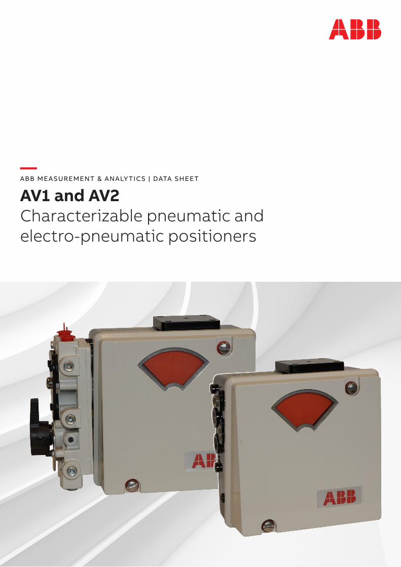
AV1 and AV2Characterizable pneumatic and electro-pneumatic positioners
2 AV1 AND AV2 CHARACTERIZABLE PNEUMATIC POSITIONERS | DS/AV12-EN REV. I
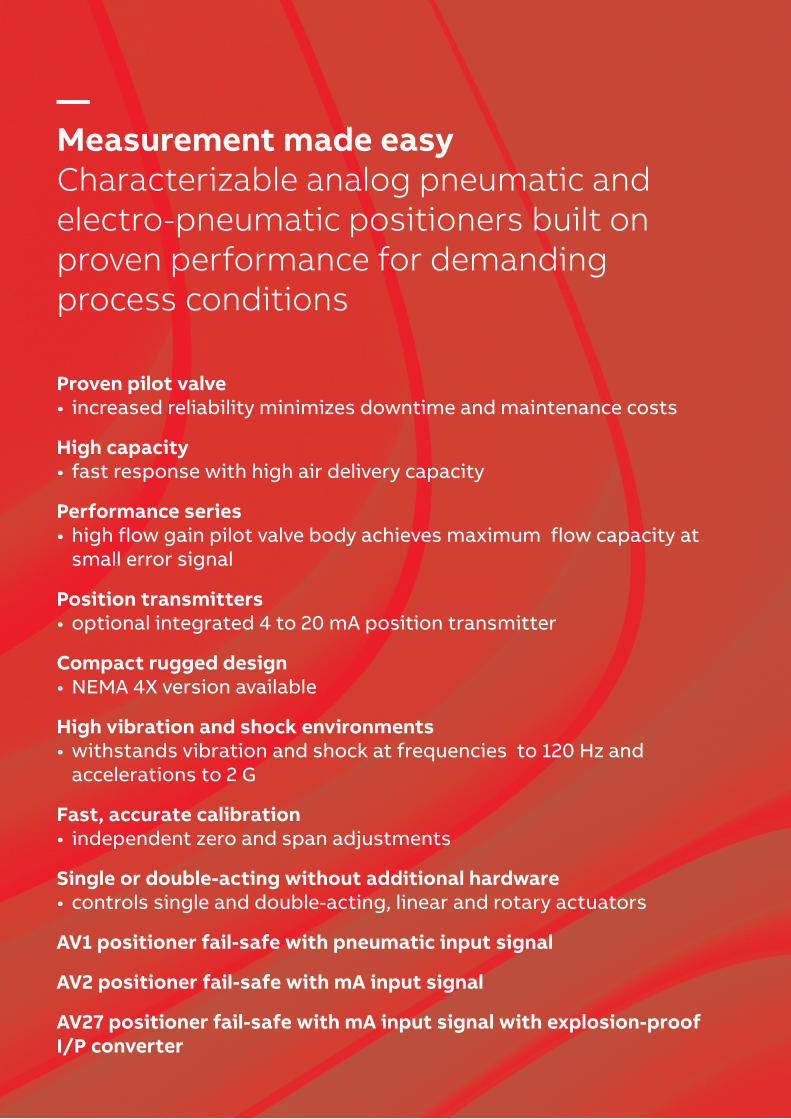
—Measurement made easyCharacterizable analog pneumatic and electro-pneumatic positioners built on proven performance for demanding process conditions
Proven pilot valve• increased reliability minimizes downtime and maintenance costs
High capacity• fast response with high air delivery capacity
Performance series• high flow gain pilot valve body achieves maximum flow capacity at
small error signal
Position transmitters• optional integrated 4 to 20 mA position transmitter
Compact rugged design• NEMA 4X version available
High vibration and shock environments• withstands vibration and shock at frequencies to 120 Hz and
accelerations to 2 G
Fast, accurate calibration• independent zero and span adjustments
Single or double-acting without additional hardware• controls single and double-acting, linear and rotary actuators
AV1 positioner fail-safe with pneumatic input signal
AV2 positioner fail-safe with mA input signal
AV27 positioner fail-safe with mA input signal with explosion-proof I/P converter
3AV1 AND AV2 CHARACTERIZABLE PNEUMATIC POSITIONERS | DS/AV12-EN REV. I
—Characterizable pneumatic positionersAV characterizable pneumatic positioners are control devices that satisfy a wide range of applications. They provide fast, sensitive and accurate positioning of pneumatic single- or double-acting, linear or rotary motion actuators. A mechanical connection from the actuator to a position feedback cam in the positioner establishes actual position. Three characterized segments on one cam provide application flexibility by establishing various relationships between input signal and actuator position. The relationships provided by the segments are square root, linear and square.
Using the cam and the zero, span and gain adjustments, the actuator responds with characteristics specific to an application.
An optional manifold assembly provides an integral shutoff and equalizing valve. This isolates the positioner from a double-acting actuator (with manual override) without removing the positioner from the process. The manifold also provides disposable filter cartridges that insure fast servicing and minimum downtime. Manifolds also contain three gage ports for mounting one instrument and two output gages. A supply gage is available and must be piped into the supply line by the user.
AV1 positioners are pneumatic positioners that use a pneumatic input to control the pneumatic output. AV2 positioners are electropneumatic positioners that use an I/P (current-to-pneumatic) converter to accept a 4 to 20 mA input signal and convert it to a pneumatic output.
Some nomenclature options include a high temperature AV1 positioner that can be operated and stored at temperatures up to 127 °C (250 °F). AV2 positioners are available with an explosion-proof I/P converter, external to the housing, that is mounted on an adapter block manifold.
The performance series provides a high flow gain pilot valve body having square ports that provide a maximized air flow for a small motion of the valve stem.
—Explosion-proof I/P converterThe AV27 positioner includes an explosion-proof I/P converter mounted to an adapter block manifold. The adapter block manifold is bolted to the outside of the main positioner housing. The unit is an AV12 positioner with the current to pneumatic (4 to 20 mA to 20.7 to 103.4 kPa (3.0 to 15.0 psig)) conversion occurring within the externally mounted I/P converter.
The 4 to 20 mA input signal wires are connected through an explosion-proof conduit entrance on the I/P converter. If no electrical connections are made within the main housing, the entire positioner can be considered suitable for application in the hazardous locations shown on the I/P label. Refer to Dimensions on page 10 for the external and mounting dimensions of the positioner.
—NEMA 4XThe positioners are available with a NEMA 4X housing. To maintain the NEMA 4X classification, the positioner must be installed as described in the NEMA 4X mounting kit. Suitable piping must be attached to the vent opening and vented in a manner to prevent the entrance of water under pressure (for example, from a hose). Additionally, the conduit connections must be suitable for a NEMA 4X rating.
4 AV1 AND AV2 CHARACTERIZABLE PNEUMATIC POSITIONERS | DS/AV12-EN REV. I
—Common specificationStandard stroke range (cam selection)*AV_ _1_ _ _ _
12.7 to 50.8 mm (0.5 to 2.0 in) linear, rotary input 45 °AV_ _2_ _ _ _
25.4 to 101.6 mm (1.0 to 4.0 in) linear, rotary input 90 °
GainTwo adjustment levels via gain hinge spring change for standard and performance series (high gain) units are available.
Supply pressure**172 to 1,034 kPa (25 to 150 psig)
Supply pressure effect0.05 % per 6.9 kPa for ±69 kPa change (0.05 % per 1.0 psig for ±10 psig change)
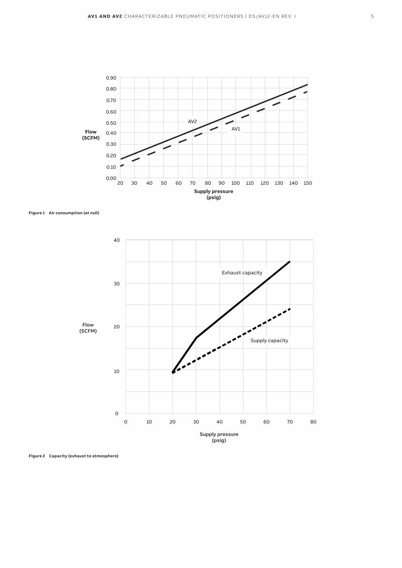
Air consumptionSee Figure 1 on page 5
CapacityMaximum capacity exhausted to atmosphere – see Figure 2 on page 5
Vibration effect***<2,0 % error for:
• 5 to 115 Hz at peak-to-peak constant displacement to 4 mm (0.16 in)
• 15 to 120 Hz at acceleration to 2 G.
Pneumatic connections1/4 NPT on supply, signal and output connections1/8 NPT on pressure gages
* Use 90° cam whenever possible
** Minimum supply pressure must be 34.4 kPa (5.0 psig) above the required operating pressure*** Tested according ISA-S75, 13 – 1989
Materials of constructionEnclosure
Aluminum and <0.5 % magnesiumPilot valve
303 stainless steel
Enclosure classificationStandard
• NEMA 3R classification when vent hole is protected from rain using rain elbow (1/2 NPT street elbow, see Figure 10 on page 11)
• NEMA 4X classification with option AV_ _ _ _ _ _N.
5AV1 AND AV2 CHARACTERIZABLE PNEUMATIC POSITIONERS | DS/AV12-EN REV. I
Flow(SCFM)
Supply pressure(psig)
AV2AV1
5030200.00
0.10
0.20
0.30
0.40
6040 70 80 90 100 110 120 130 140 150
0.50
0.60
0.70
0.80
0.90
Figure 1 Air consumption (at null)
Flow(SCFM)
Supply pressure(psig)
Exhaust capacity
Supply capacity
20100
0
10
20
30
40
30 40 50 60 70 80
Figure 2 Capacity (exhaust to atmosphere)
6 AV1 AND AV2 CHARACTERIZABLE PNEUMATIC POSITIONERS | DS/AV12-EN REV. I
—AV1 positioner specificationOperationInput range*
• AV11 and AV15 – 20.7 to 103.4 kPa (3.0 to 15.0 psig)
• AV12 and AV16 – 20.7 to 186.2 kPa (3.0 to 27.0 psig)
Accuracy**0.80 % of span maximum
Resolution0.09 % of span maximum
Hysteresis**0.45 % of span maximum
Repeatability**0.12 % of span maximum
Deadband**0.12 % of span maximum
Linearity**0.70 % of span maximum
Weight1.84 kg (4.06 lb)
Temperature limitsOperating***
AV11/2 –40 to 82 °C (–40 to 180 °F)AV15/6 –20 to 121 °C (–4 to 250 °F)
StorageAV11/2 –40 to 93 °C (–40 to 200 °F)AV15/6 –20 to 121 °C (–4 to 250 °F)
Humidity limits – operating and storage0 to 95 % non condensing
* Units have 50 % range suppression and / or zero elevation capability.
** Tested according ISA-S75, 13 – 1989
*** For operation below 4.4 °C (40 °F), dew point of supply air must be 10 °C (18 °F) lower than lowest expected operating temperature
—AV2 positioner specificationOperationInput range*
4 to 20mAInput impedance
250 Ω at 20 mAAccuracy**
0.90 % of span maximumResolution
0.30 % of span maximumHysteresis**
0.70 % of span maximumRepeatability**
0.50 % of span maximumDeadband**
0.30 % of span maximumLinearity**
0.70% of span maximum
WeightStandard model
2.32 kg (5.11 lb)Explosion-proof model
2.95 kg (6.51 lb)
Temperature limitsOperating***
–20 to 82 °C (–4 to 180 °F)Storage
–20 to 80 °C (–4 to 176 °F)
Humidity limitsOperating and storage
0 to 95% non condensing
7AV1 AND AV2 CHARACTERIZABLE PNEUMATIC POSITIONERS | DS/AV12-EN REV. I
—AV1/2_ _ _1 position transmitter specification
Total resistance2000 Ω, ±20 % potentiometer
Power rating• 1 W up to 70 °C (158 °F),• 0 W at or above 125 °C (257 °F)
Wiper rate of change9.9 Ω nominal per degree of cam rotation
Temperature effect0.05 % (500 ppm) per °C (0.03 % [278 ppm] per °F) maximum
Maximum voltage35 V DC or 30 V AC across the potentiometer ends
Temperature limitsOperating
–40 to 82 °C (–40 to 180 °F)Storage
–40 to 93 °C (–40 to 200 °F)
8 AV1 AND AV2 CHARACTERIZABLE PNEUMATIC POSITIONERS | DS/AV12-EN REV. I
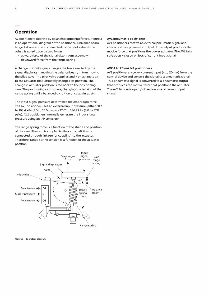
—OperationAV positioners operate by balancing opposing forces. Figure 3 is an operational diagram of the positioner. A balance beam, hinged at one end and connected to the pilot valve at the other, is acted upon by two forces:
• upward force of the signal diaphragm assembly• downward force from the range spring
A change in input signal changes the force exerted by the signal diaphragm, moving the balance beam, in turn moving the pilot valve. The pilot valve supplies and / or exhausts air to the actuator that ultimately changes its position. The change in actuator position is fed back to the positioning cam. The positioning cam moves, changing the tension of the range spring until a balanced condition once again exists.
The input signal pressure determines the diaphragm force. The AV1 positioner uses an external input pressure (either 20.7 to 103.4 kPa (3.0 to 15.0 psig) or 20.7 to 186.2 kPa (3.0 to 27.0 psig). AV2 positioners internally generate the input signal pressure using an I/P converter.
The range spring force is a function of the shape and position of the cam. The cam is coupled to the cam shaft that is connected through linkage (or coupling) to the actuator. Therefore, range spring tension is a function of the actuator position.
Diaphragm force
Rangespringforce
Inputsignal
pressure
Balance beam
GainhingespringSignal diaphragm
Range spring
Cam
Pilot valve
To actuator
Supply pressure
To actuator
O1
S
O2
Figure 3 Operation diagram
AV1 pneumatic positionerAV1 positioners receive an external pneumatic signal and converts it to a pneumatic output. This output produces the motive force that positions the power actuator. The AV1 fails safe open / closed on loss of current input signal.
AV2 4 to 20 mA I/P positionersAV2 positioners receive a current input (4 to 20 mA) from the control device and convert the signal to a pneumatic signal. This pneumatic signal is converted to a pneumatic output that produces the motive force that positions the actuator. The AV2 fails safe open / closed on loss of current input signal.
9AV1 AND AV2 CHARACTERIZABLE PNEUMATIC POSITIONERS | DS/AV12-EN REV. I
Position transmittersTwo types of position transmitters are available on AV1 and AV2 positioners.
The potentiometric position transmitter uses a high durability plastic film potentiometer to indicate the position of the cam shaft. The resulting resistive value is a function of the shaft position. The resistive output can be used for additional control purposes.
The 4 to 20 mA position transmitter uses a high durability plastic film potentiometer to indicate the cam shaft position. The resulting resistive value is sent to an electronics assembly that produces a proportional 4 to 20 mA signal. This signal can be used for additional control purposes.
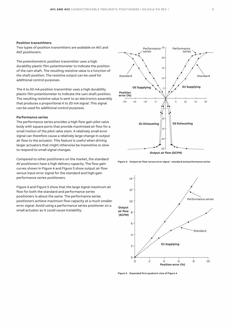
Performance seriesThe performance series provides a high flow gain pilot valve body with square ports that provide maximized air flow for a small motion of the pilot valve stem. A relatively small error signal can therefore cause a relatively large change in output air flow to the actuator. This feature is useful when driving larger actuators that might otherwise be insensitive or slow to respond to small signal changes.
Compared to other positioners on the market, the standard AV positioners have a high delivery capacity. The flow gain curves shown in Figure 4 and Figure 5 show output air flow versus input error signal for the standard and high-gain performance series positioners.
Figure 4 and Figure 5 show that the large signal maximum air flow for both the standard and performance series positioners is about the same. The performance series positioners achieve maximum flow capacity at a much smaller error signal. Avoid using a performance series positioner on a small actuator as it could cause instability.
Performance series
Positionerror (%)
O2 Supplying O1 Supplying
O1 Exhausting O2 Exhausting
Output air flow (SCFM)
Performance series
Standard Standard
5–5
5
10
15
20
25
–20
–25
10–10–15–20 15 20
–5
–10
–15
Figure 4 Output air flow versus error signal - standard and performance series
Performance series
Position error (%)
O1 Supplying
Output air flow (SCFM)
Standard
10864200
2
4
6
8
10
12
14
Figure 5 Expanded first quadrant view of Figure 4
10 AV1 AND AV2 CHARACTERIZABLE PNEUMATIC POSITIONERS | DS/AV12-EN REV. I
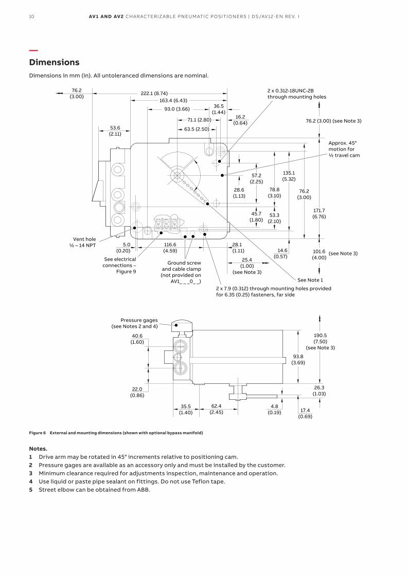
—DimensionsDimensions in mm (in). All untoleranced dimensions are nominal.
Vent hole½ – 14 NPT
See electricalconnections –
Figure 9
Ground screwand cable clamp
(not provided onAV1_ _ _0_ _)
2 x 0.312-18UNC-2Bthrough mounting holes
2 x 7.9 (0.312) through mounting holes provided for 6.35 (0.25) fasteners, far side
Approx. 45°motion for½ travel cam
76.2(3.00)
36.5(1.44)
16.2(0.64)
14.6(0.57)
28.6(1.13)
45.7(1.80)
53.3(2.10)
25.4(1.00)
(see Note 3)
28.1(1.11)
116.6(4.59)
5.0(0.20)
53.6(2.11)
See Note 1
76.2 (3.00) (see Note 3)
(see Note 3)101.6(4.00)
171.7(6.76)
76.2(3.00)
135.1(5.32)
57.2(2.25)
78.8(3.10)
222.1 (8.74)163.4 (6.43)
93.0 (3.66)
71.1 (2.80)
63.5 (2.50)
17.4(0.69)
4.8(0.19)
62.4(2.45)
40.6(1.60)
22.0(0.86)
35.5(1.40)
26.3(1.03)
Pressure gages(see Notes 2 and 4)
190.5(7.50)
(see Note 3)
93.8(3.69)
Figure 6 External and mounting dimensions (shown with optional bypass manifold)
Notes.1 Drive arm may be rotated in 45° increments relative to positioning cam.2 Pressure gages are available as an accessory only and must be installed by the customer.3 Minimum clearance required for adjustments inspection, maintenance and operation.4 Use liquid or paste pipe sealant on fittings. Do not use Teflon tape.5 Street elbow can be obtained from ABB.
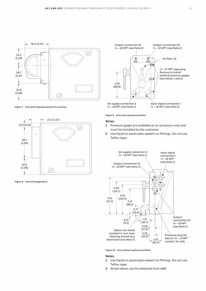
11AV1 AND AV2 CHARACTERIZABLE PNEUMATIC POSITIONERS | DS/AV12-EN REV. I
53.3(2.10)
58.7(2.31)
52.8(2.08)
78.0 (3.07)
Figure 7 View with explosion proof I/P converter
27.2 (1.07)
13.0 (0.51)
99.1(3.90)
52.8(2.08)
Figure 8 View with gage block
01 0202
01
S II
Air filter (3)
Output connection 01¼ – 18 NPT (see Note 2)
Output connection 02¼ – 18 NPT (see Note 2)
⅛ – 27 NPT pipe plug. Remove to install optional pressure gages(see Notes 1 and 2)
3.50(88.8)
Air supply connection S¼ – 18 NPT (see Note 2)
Input signal connection I¼ – 18 NPT (see Note 2)
Figure 9 View with optional manifold
Notes.1 Pressure gages are available as an accessory only and
must be installed by the customer.2 Use liquid or paste pipe sealant on fittings. Do not use
Teflon tape.
02
01
S
I
0.77(19.4)
1.21(30.7)
0.69(17.5)
0.76(19.3)
1.67(42.3)
0.37(9.3)
Output connection 01¼ – 18 NPT (see Note 1)
Elbow rain shieldinstalled in vent hole.Opening should face
downward (see Note 2)
Air supply connection S¼ – 18 NPT (see Note 1)
Input signalconnection I¼ – 18 NPT (see Note 1)
Output connection 02¼ – 18 NPT (see Note 1)
Knockout plug for electric ½ – 14 NPT conduit, far side
3.47(88.2)
4.03(102.4)
4.60(116.7)
5.41(37.4)
Figure 10 View without optional manifold
Notes.1 Use liquid or paste pipe sealant on fittings. Do not use
Teflon tape.2 Street elbow can be obtained from ABB.
12 AV1 AND AV2 CHARACTERIZABLE PNEUMATIC POSITIONERS | DS/AV12-EN REV. I
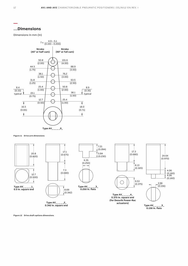
—…DimensionsDimensions in mm (in)
101.6(4.00)
76.2(3.00)
50.8(2.00)
38.1(1.50)
25.4(1.00)
25.4(1.00)
12.7(0.50)
38.1(1.50)
44.5(1.75)
50.8(2.00)
4.9 – 5.1(0.193 – 0.200)7 x
Stroke(90° or full cam)
Type AV_ _ _ _ _0_
Stroke(45° or half cam)
19.1(0.75)
31.8(1.25)
88.9(3.50)
63.5(2.50)
18.0(0.71)
16.5(0.65)
8.9(0.35)typical
8.4(0.33)typical
Figure 11 Drive arm dimensions
7.21(0.284)
Type AV_ _ _ _ _3_0.250 in. flats
5.84(0.230)
6.35(0.250)
Type AV_ _ _ _ _5_0.156 in. flats
24.64(0.970)
4.06(0.160)4.06(0.160)
3.96(0.156)
17.3(0.680)
9.53(0.375)
Type AV_ _ _ _ _4_0.375 in. square end
(for Dezurik Power-Racactuators)
8.13(0.320)
17.1(0.675)
Type AV_ _ _ _ _2_0.342 in. square end
8.69(0.342)
7.3(0.680)12.7
(0.500)
Type AV_ _ _ _ _1_0.5 in. square end
20.8(0.820)
Figure 12 Drive shaft options dimensions
13AV1 AND AV2 CHARACTERIZABLE PNEUMATIC POSITIONERS | DS/AV12-EN REV. I
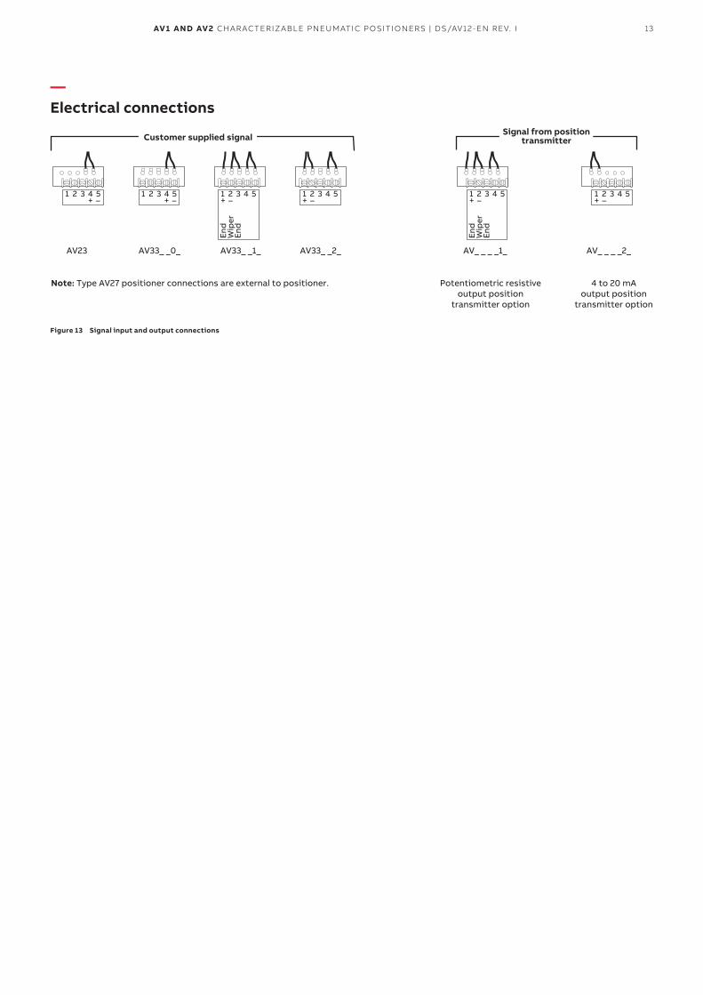
—Electrical connections
Signal from positiontransmitterCustomer supplied signal
AV_ _ _ _1_ AV_ _ _ _2_
4 to 20 mAoutput position
transmitter option
Potentiometric resistiveoutput position
transmitter option
Note: Type AV27 positioner connections are external to positioner.
1 2 3 4 5+ –
AV33_ _2_
1 2 3 4 5+ –
AV23
1 2 3 4 5+ –
AV33_ _0_
1 2 3 4 5+ –
1 2
End
End
Wip
er
3 4 5+ –
AV33_ _1_
1 2
End
End
Wip
er
3 4 5+ –
Figure 13 Signal input and output connections
14 AV1 AND AV2 CHARACTERIZABLE PNEUMATIC POSITIONERS | DS/AV12-EN REV. I
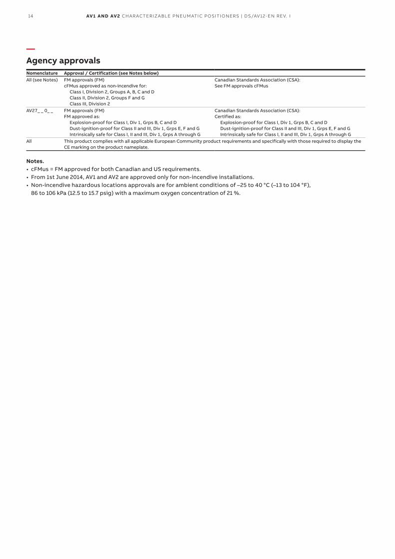
—Agency approvalsNomenclature Approval / Certification (see Notes below)All (see Notes) FM approvals (FM)
cFMus approved as non-incendive for:Class I, Division 2, Groups A, B, C and D Class II, Division 2, Groups F and G Class III, Division 2
Canadian Standards Association (CSA):See FM approvals cFMus
AV27_ _ 0_ _ FM approvals (FM) FM approved as:
Explosion-proof for Class I, Div 1, Grps B, C and D Dust-ignition-proof for Class II and III, Div 1, Grps E, F and G Intrinsically safe for Class I, II and III, Div 1, Grps A through G
Canadian Standards Association (CSA):Certified as:
Explosion-proof for Class I, Div 1, Grps B, C and D Dust-ignition-proof for Class II and III, Div 1, Grps E, F and G Intrinsically safe for Class I, II and III, Div 1, Grps A through G
All This product complies with all applicable European Community product requirements and specifically with those required to display the CE marking on the product nameplate.
Notes.• cFMus = FM approved for both Canadian and US requirements.• From 1st June 2014, AV1 and AV2 are approved only for non-incendive installations.• Non-incendive hazardous locations approvals are for ambient conditions of –25 to 40 °C (–13 to 104 °F),
86 to 106 kPa (12.5 to 15.7 psig) with a maximum oxygen concentration of 21 %.
15AV1 AND AV2 CHARACTERIZABLE PNEUMATIC POSITIONERS | DS/AV12-EN REV. I
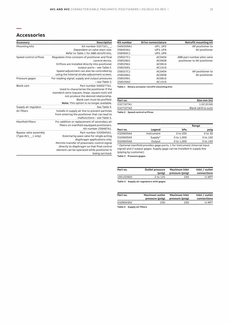
—AccessoriesAccessory DescriptionMounting kits Kit number 5327321_ _.
Dependent on valve stem size. Refer to Table 1 for ABB retrofit kits.
Speed control orifices Regulates time constant of positioner and final control device.
Orifices are installed directly into positioner output ports – see Table 2.
Speed adjustment can also be controlled by using the internal stroke adjustment screws.
Pressure gages For reading signal, supply and output pressures – see Table 3.
Blank cam Part number 5400277A1. Used to characterize the positioner if the
standard cams (square, linear, square root) will not produce the desired relationship.
Blank cam must be profiled. Note: This option is no longer available.
Supply air regulator See Table 4.Air filters Installs in supply air line to prevent particles
from entering the positioner that can lead to malfunctions – see Table 5.
Manifold filters For addition or replacement of secondary air filters on manifold-equipped positioners.
Kit number 258487A1.Bypass valve assembly (Type AV1_ _1 only)
Part number 5326945A1. External by-pass valve for single-acting
diaphragm applications only. Permits transfer of pneumatic control signal
directly to diaphragm so that final control element can be operated while positioner is
being serviced.
Kit number Drive nomenclature Retrofit mounting kit5400309A1 258493A1 258494C1
UP1, UP2 UP3, UP4 UP5, UP6
AP positioner to AV positioner
258527C1 258528A1 258529A1 258530A1
AC0404 AC0608 AC0816 AC1016
ABB part number pilot valve positioner to AV positioner
258527C1 258528A1 258529A1 258530A2
AC0404 AC0608 AC0816 AC1016
AP positioner to AV positioner
Table 1 Rotary actuator retrofit mounting kits
Part no. Size mm (in)5327327A1 1.02 (0.04)5327327A2 Blank (drill to suit)Table 2 Speed control orifices
RangePart no. Legend kPa psig5326605A4 Instrument 0 to 200 0 to 305326605A5 Supply* 0 to 1,000 0 to 1605326605A6 Output 0 to 1,000 0 to 160* Optional manifold provides gage ports, 1 for instrument (internal input signal) and 2 output gages. Supply gage can be installed in supply line (piping by customer).Table 3 Pressure gages
Part no. Outlet pressure (psig)
Maximum inlet pressure (psig)
Inlet / outlet connections
1951029D5 2 to 125 250 1/4 NPT
Table 4 Supply air regulators with gages
Part no. Maximum outlet pressure (psig)
Maximum inlet pressure (psig)
Inlet / outlet connections
5328563D2 250 250 1/4 NPT
Table 5 Supply air filters
16 AV1 AND AV2 CHARACTERIZABLE PNEUMATIC POSITIONERS | DS/AV12-EN REV. I
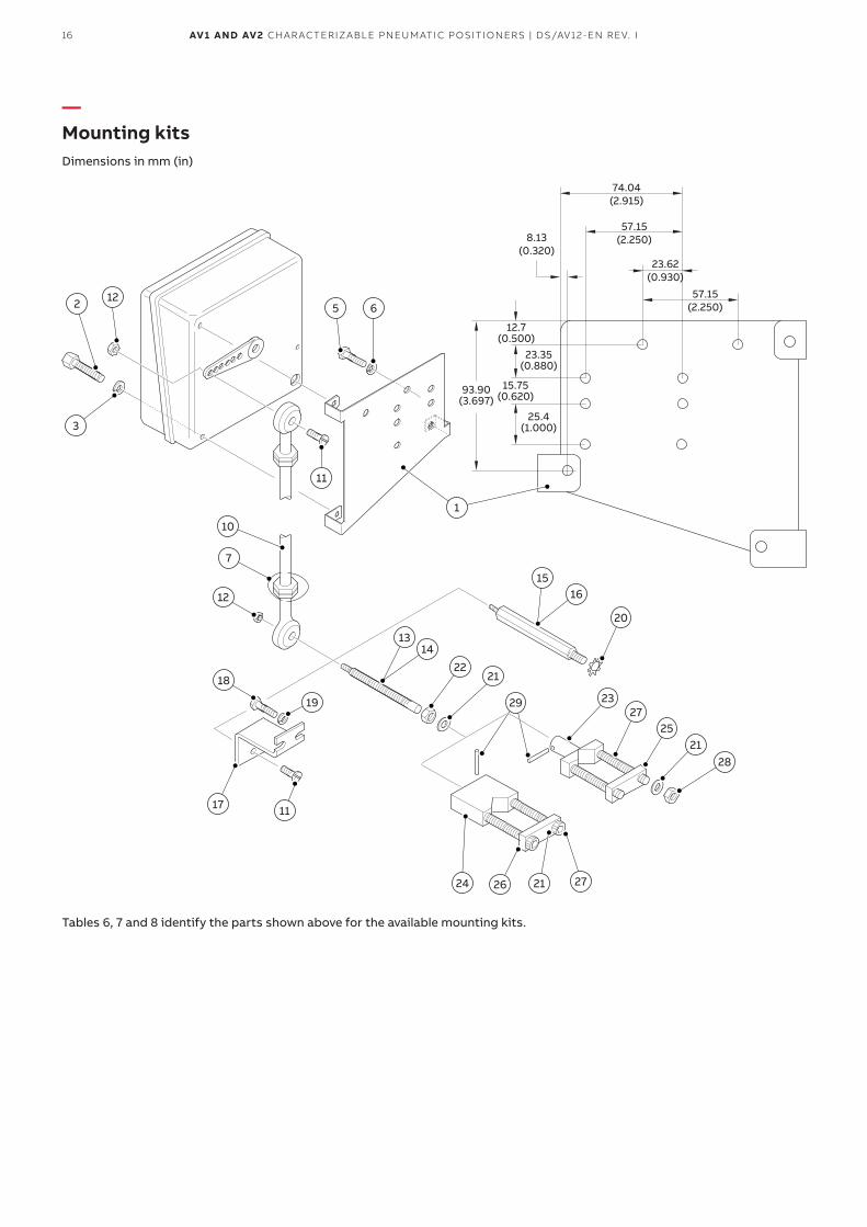
—Mounting kitsDimensions in mm (in)
12
3
2 5 6
1
11
10
7
12
18
17 11
24 26 21 27
2221
29 2327
2521
28
20
19
1314
1516
74.04(2.915)
57.15(2.250)
23.62(0.930)
57.15(2.250)
8.13(0.320)
12.7(0.500)
23.35(0.880)
15.75(0.620)
25.4(1.000)
93.90(3.697)
Tables 6, 7 and 8 identify the parts shown above for the available mounting kits.
17AV1 AND AV2 CHARACTERIZABLE PNEUMATIC POSITIONERS | DS/AV12-EN REV. I
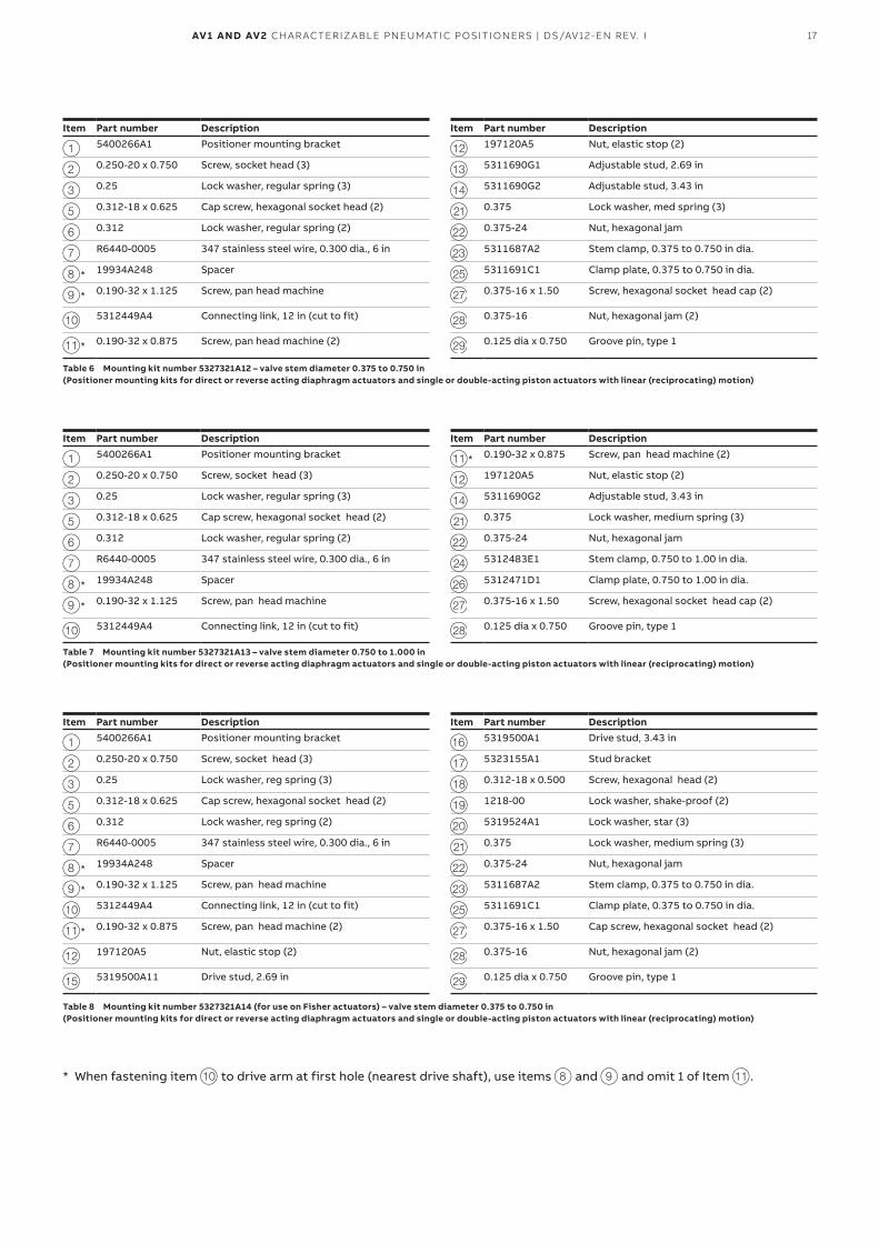
Item Part number Description Item Part number Description
1 5400266A1 Positioner mounting bracket l 197120A5 Nut, elastic stop (2)
2 0.250-20 x 0.750 Screw, socket head (3) m 5311690G1 Adjustable stud, 2.69 in
3 0.25 Lock washer, regular spring (3) n 5311690G2 Adjustable stud, 3.43 in
5 0.312-18 x 0.625 Cap screw, hexagonal socket head (2) u 0.375 Lock washer, med spring (3)
6 0.312 Lock washer, regular spring (2) v 0.375-24 Nut, hexagonal jam
7 R6440-0005 347 stainless steel wire, 0.300 dia., 6 in w 5311687A2 Stem clamp, 0.375 to 0.750 in dia.
8* 19934A248 Spacer y 5311691C1 Clamp plate, 0.375 to 0.750 in dia.
9* 0.190-32 x 1.125 Screw, pan head machine 27 0.375-16 x 1.50 Screw, hexagonal socket head cap (2)
j 5312449A4 Connecting link, 12 in (cut to fit) 28 0.375-16 Nut, hexagonal jam (2)
k* 0.190-32 x 0.875 Screw, pan head machine (2) 29 0.125 dia x 0.750 Groove pin, type 1
Table 6 Mounting kit number 5327321A12 – valve stem diameter 0.375 to 0.750 in (Positioner mounting kits for direct or reverse acting diaphragm actuators and single or double-acting piston actuators with linear (reciprocating) motion)
Item Part number Description Item Part number Description
1 5400266A1 Positioner mounting bracket k* 0.190-32 x 0.875 Screw, pan head machine (2)
2 0.250-20 x 0.750 Screw, socket head (3) l 197120A5 Nut, elastic stop (2)
3 0.25 Lock washer, regular spring (3) n 5311690G2 Adjustable stud, 3.43 in
5 0.312-18 x 0.625 Cap screw, hexagonal socket head (2) u 0.375 Lock washer, medium spring (3)
6 0.312 Lock washer, regular spring (2) v 0.375-24 Nut, hexagonal jam
7 R6440-0005 347 stainless steel wire, 0.300 dia., 6 in x 5312483E1 Stem clamp, 0.750 to 1.00 in dia.
8* 19934A248 Spacer z 5312471D1 Clamp plate, 0.750 to 1.00 in dia.
9* 0.190-32 x 1.125 Screw, pan head machine 27 0.375-16 x 1.50 Screw, hexagonal socket head cap (2)
j 5312449A4 Connecting link, 12 in (cut to fit) 28 0.125 dia x 0.750 Groove pin, type 1
Table 7 Mounting kit number 5327321A13 – valve stem diameter 0.750 to 1.000 in (Positioner mounting kits for direct or reverse acting diaphragm actuators and single or double-acting piston actuators with linear (reciprocating) motion)
Item Part number Description Item Part number Description
1 5400266A1 Positioner mounting bracket p 5319500A1 Drive stud, 3.43 in
2 0.250-20 x 0.750 Screw, socket head (3) q 5323155A1 Stud bracket
3 0.25 Lock washer, reg spring (3) r 0.312-18 x 0.500 Screw, hexagonal head (2)
5 0.312-18 x 0.625 Cap screw, hexagonal socket head (2) s 1218-00 Lock washer, shake-proof (2)
6 0.312 Lock washer, reg spring (2) t 5319524A1 Lock washer, star (3)
7 R6440-0005 347 stainless steel wire, 0.300 dia., 6 in u 0.375 Lock washer, medium spring (3)
8* 19934A248 Spacer v 0.375-24 Nut, hexagonal jam
9* 0.190-32 x 1.125 Screw, pan head machine w 5311687A2 Stem clamp, 0.375 to 0.750 in dia.
j 5312449A4 Connecting link, 12 in (cut to fit) y 5311691C1 Clamp plate, 0.375 to 0.750 in dia.
k* 0.190-32 x 0.875 Screw, pan head machine (2) 27 0.375-16 x 1.50 Cap screw, hexagonal socket head (2)
l 197120A5 Nut, elastic stop (2) 28 0.375-16 Nut, hexagonal jam (2)
o 5319500A11 Drive stud, 2.69 in 29 0.125 dia x 0.750 Groove pin, type 1
Table 8 Mounting kit number 5327321A14 (for use on Fisher actuators) – valve stem diameter 0.375 to 0.750 in (Positioner mounting kits for direct or reverse acting diaphragm actuators and single or double-acting piston actuators with linear (reciprocating) motion)
* When fastening item j to drive arm at first hole (nearest drive shaft), use items 8 and 9 and omit 1 of Item k.
18 AV1 AND AV2 CHARACTERIZABLE PNEUMATIC POSITIONERS | DS/AV12-EN REV. I
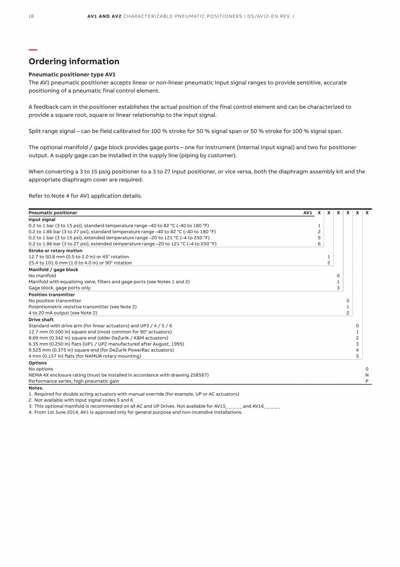
—Ordering informationPneumatic positioner type AV1The AV1 pneumatic positioner accepts linear or non-linear pneumatic input signal ranges to provide sensitive, accurate positioning of a pneumatic final control element.
A feedback cam in the positioner establishes the actual position of the final control element and can be characterized to provide a square root, square or linear relationship to the input signal.
Split range signal – can be field calibrated for 100 % stroke for 50 % signal span or 50 % stroke for 100 % signal span.
The optional manifold / gage block provides gage ports – one for instrument (internal input signal) and two for positioner output. A supply gage can be installed in the supply line (piping by customer).
When converting a 3 to 15 psig positioner to a 3 to 27 input positioner, or vice versa, both the diaphragm assembly kit and the appropriate diaphragm cover are required.
Refer to Note 4 for AV1 application details.
Pneumatic positioner AV1 X X X X X XInput signal0.2 to 1 bar (3 to 15 psi), standard temperature range –40 to 82 °C (–40 to 180 °F) 0.2 to 1.86 bar (3 to 27 psi), standard temperature range –40 to 82 °C (–40 to 180 °F) 0.2 to 1 bar (3 to 15 psi), extended temperature range –20 to 121 °C (–4 to 250 °F) 0.2 to 1.86 bar (3 to 27 psi), extended temperature range –20 to 121 °C (–4 to 250 °F)
1 2 5 6
Stroke or rotary motion12.7 to 50.8 mm (0.5 to 2.0 in) or 45° rotation 25.4 to 101.6 mm (1.0 to 4.0 in) or 90° rotation
1 2
Manifold / gage blockNo manifold Manifold with equalizing valve, filters and gage ports (see Notes 1 and 2) Gage block, gage ports only
0 1 3
Position transmitterNo position transmitter Potentiometric resistive transmitter (see Note 2) 4 to 20 mA output (see Note 2)
0 1 2
Drive shaftStandard with drive arm (for linear actuators) and UP3 / 4 / 5 / 6 12.7 mm (0.500 in) square end (most common for 90° actuators) 8.69 mm (0.342 in) square end (older DeZurik / K&M actuators) 6.35 mm (0.250 in) flats (UP1 / UP2 manufactured after August, 1995) 9.525 mm (0.375 in) square end (for DeZurik PowerRac actuators) 4 mm (0.157 in) flats (for NAMUR rotary mounting)
0 1 2 3 4 5
OptionsNo options NEMA 4X enclosure rating (must be installed in accordance with drawing 258567) Performance series, high pneumatic gain
0 N P
Notes.1. Required for double acting actuators with manual override (for example, UP or AC actuators)2. Not available with input signal codes 5 and 63. This optional manifold is recommended on all AC and UP Drives. Not available for AV15_ _ _ _ _ and AV16_ _ _ _ _4. From 1st June 2014, AV1 is approved only for general purpose and non-incendive installations.
19AV1 AND AV2 CHARACTERIZABLE PNEUMATIC POSITIONERS | DS/AV12-EN REV. I
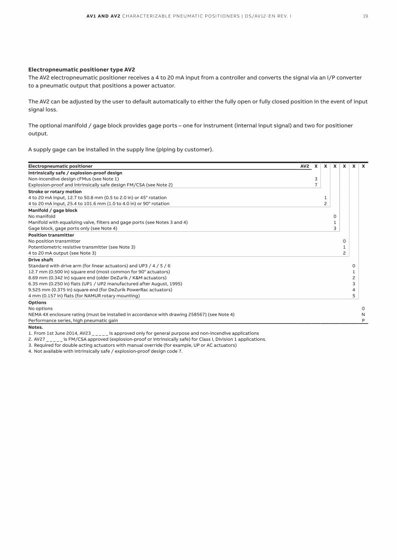
Electropneumatic positioner type AV2The AV2 electropneumatic positioner receives a 4 to 20 mA input from a controller and converts the signal via an I/P converter to a pneumatic output that positions a power actuator.
The AV2 can be adjusted by the user to default automatically to either the fully open or fully closed position in the event of input signal loss.
The optional manifold / gage block provides gage ports – one for instrument (internal input signal) and two for positioner output.
A supply gage can be installed in the supply line (piping by customer).
Electropneumatic positioner AV2 X X X X X XIntrinsically safe / explosion-proof designNon-incendive design cFMus (see Note 1) Explosion-proof and intrinsically safe design FM/CSA (see Note 2)
3 7
Stroke or rotary motion4 to 20 mA input, 12.7 to 50.8 mm (0.5 to 2.0 in) or 45° rotation 4 to 20 mA input, 25.4 to 101.6 mm (1.0 to 4.0 in) or 90° rotation
1 2
Manifold / gage blockNo manifold Manifold with equalizing valve, filters and gage ports (see Notes 3 and 4) Gage block, gage ports only (see Note 4)
0 1 3
Position transmitterNo position transmitter Potentiometric resistive transmitter (see Note 3) 4 to 20 mA output (see Note 3)
0 1 2
Drive shaftStandard with drive arm (for linear actuators) and UP3 / 4 / 5 / 6 12.7 mm (0.500 in) square end (most common for 90° actuators) 8.69 mm (0.342 in) square end (older DeZurik / K&M actuators) 6.35 mm (0.250 in) flats (UP1 / UP2 manufactured after August, 1995) 9.525 mm (0.375 in) square end (for DeZurik PowerRac actuators) 4 mm (0.157 in) flats (for NAMUR rotary mounting)
0 1 2 3 4 5
OptionsNo options NEMA 4X enclosure rating (must be installed in accordance with drawing 258567) (see Note 4) Performance series, high pneumatic gain
0 N P
Notes.1. From 1st June 2014, AV23 _ _ _ _ _ is approved only for general purpose and non-incendive applications2. AV27 _ _ _ _ _ is FM/CSA approved (explosion-proof or intrinsically safe) for Class I, Division 1 applications.3. Required for double acting actuators with manual override (for example, UP or AC actuators)4. Not available with intrinsically safe / explosion-proof design code 7.
20 AV1 AND AV2 CHARACTERIZABLE PNEUMATIC POSITIONERS | DS/AV12-EN REV. I
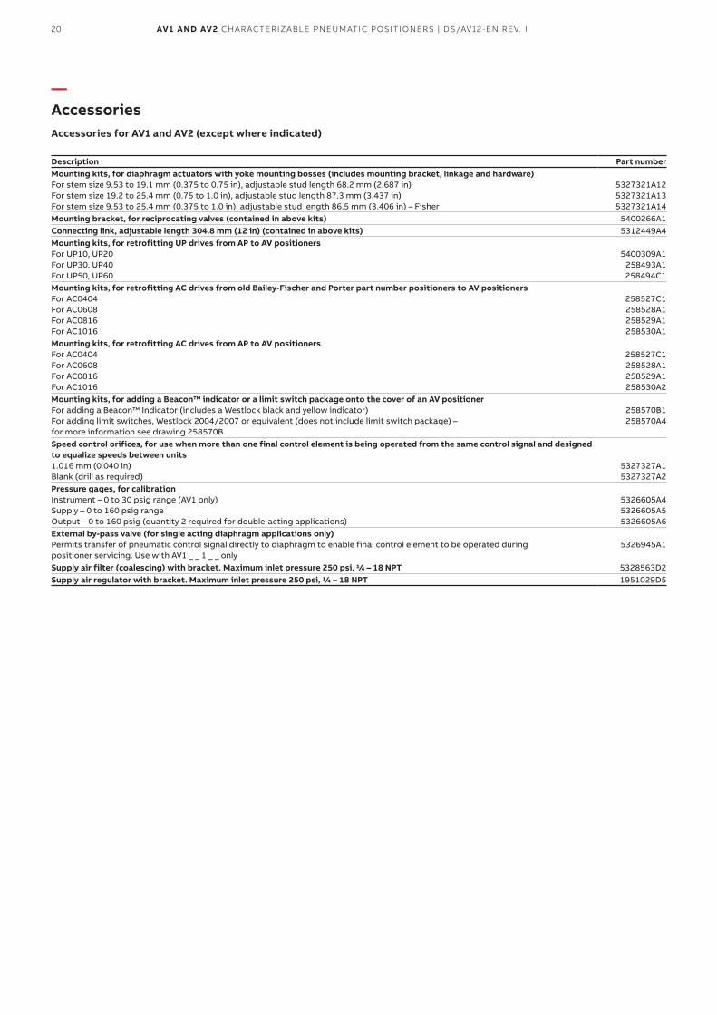
—AccessoriesAccessories for AV1 and AV2 (except where indicated)
Description Part numberMounting kits, for diaphragm actuators with yoke mounting bosses (includes mounting bracket, linkage and hardware)For stem size 9.53 to 19.1 mm (0.375 to 0.75 in), adjustable stud length 68.2 mm (2.687 in) For stem size 19.2 to 25.4 mm (0.75 to 1.0 in), adjustable stud length 87.3 mm (3.437 in) For stem size 9.53 to 25.4 mm (0.375 to 1.0 in), adjustable stud length 86.5 mm (3.406 in) – Fisher
5327321A12 5327321A13 5327321A14
Mounting bracket, for reciprocating valves (contained in above kits) 5400266A1Connecting link, adjustable length 304.8 mm (12 in) (contained in above kits) 5312449A4Mounting kits, for retrofitting UP drives from AP to AV positionersFor UP10, UP20 For UP30, UP40 For UP50, UP60
5400309A1 258493A1 258494C1
Mounting kits, for retrofitting AC drives from old Bailey-Fischer and Porter part number positioners to AV positionersFor AC0404 For AC0608 For AC0816 For AC1016
258527C1 258528A1 258529A1 258530A1
Mounting kits, for retrofitting AC drives from AP to AV positionersFor AC0404 For AC0608 For AC0816 For AC1016
258527C1 258528A1 258529A1 258530A2
Mounting kits, for adding a Beacon™ indicator or a limit switch package onto the cover of an AV positionerFor adding a Beacon™ Indicator (includes a Westlock black and yellow indicator) For adding limit switches, Westlock 2004/2007 or equivalent (does not include limit switch package) – for more information see drawing 258570B
258570B1 258570A4
Speed control orifices, for use when more than one final control element is being operated from the same control signal and designed to equalize speeds between units1.016 mm (0.040 in) Blank (drill as required)
5327327A1 5327327A2
Pressure gages, for calibrationInstrument – 0 to 30 psig range (AV1 only) Supply – 0 to 160 psig range Output – 0 to 160 psig (quantity 2 required for double-acting applications)
5326605A4 5326605A5 5326605A6
External by-pass valve (for single acting diaphragm applications only)Permits transfer of pneumatic control signal directly to diaphragm to enable final control element to be operated during positioner servicing. Use with AV1 _ _ 1 _ _ only
5326945A1
Supply air filter (coalescing) with bracket. Maximum inlet pressure 250 psi, 1/4 – 18 NPT 5328563D2Supply air regulator with bracket. Maximum inlet pressure 250 psi, 1/4 – 18 NPT 1951029D5
21AV1 AND AV2 CHARACTERIZABLE PNEUMATIC POSITIONERS | DS/AV12-EN REV. I
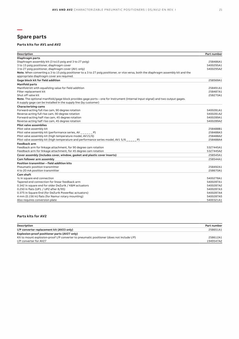
—Spare partsParts kits for AV1 and AV2
Description Part numberDiaphragm partsDiaphragm assembly kit (3 to15 psig and 3 to 27 psig) 3 to 15 psig positioner, diaphragm cover 3 to 27 psig positioner, diaphragm cover (AV1 only) Note. When converting a 3 to 15 psig positioner to a 3 to 27 psig positioner, or vice versa, both the diaphragm assembly kit and the appropriate diaphragm cover are required.
258486A1 5400295A1 5400295A2
Gage block kit for field addition 258569A1Manifold partsManifold kit with equalizing value for field addition Filter replacement kit Shut off valve kit Note. The optional manifold/gage block provides gage ports – one for instrument (internal input signal) and two output gages. A supply gage can be installed in the supply line (by customer)
258491A1 258487A1 258270A1
Characterizing camsForward-acting full rise cam, 90 degree rotation Reverse-acting full rise cam, 90 degree rotation Forward-acting half rise cam, 45 degree rotation Reverse-acting half rise cam, 45 degree rotation
5400281A1 5400281A2 5400289A1 5400289A2
Pilot valve assembliesPilot valve assembly kit Pilot valve assembly kit (performance series, AV _ _ _ _ _ _ P) Pilot valve assembly kit (high temperature model, AV15/6) Pilot valve assembly kit (high temperature and performance series model, AV1 5/6 _ _ _ _ _ P)
258488B1 258488A3 258488A2 258488A4
Feedback armFeedback arm for linkage attachment, for 90 degree cam rotation Feedback arm for linkage attachment, for 45 degree cam rotation
5327445A1 5327445A2
Cover assembly (includes cover, window, gasket and plastic cover inserts) 258545A1Cam follower arm assembly 258544A1Position transmitter – field addition kits Pneumatic position transmitter 4 to 20 mA position transmitter
258492A1 258670A1
Cam shaft1/2 in square end connection Tapered end connection for linear feedback arm 0.342 in square end for older DeZurik / K&M actuators 0.250 in flats (UP1 / UP2 after 8/95) 0.375 in Square End (for DeZurik PowerRac actuators) 4 mm (0.156 in) flats (for Namur rotary mounting) Also requires conversion plate
5400278A1 5400287A1 5400287A2 5400287A3 5400287A4 5400287A5 5400321A1
Parts kits for AV2
Description Part numberI/P converter replacement kit (AV23 only) 258651A1Explosion-proof positioner parts (AV27 only)Kit to mount explosion-proof I/P converter to pneumatic positioner (does not include I/P) I/P converter for AV27
258612A1 1949547A2

22 AV1 AND AV2 CHARACTERIZABLE PNEUMATIC POSITIONERS | DS/AV12-EN REV. I
Sales Service
—Notes

23AV1 AND AV2 CHARACTERIZABLE PNEUMATIC POSITIONERS | DS/AV12-EN REV. I
DS
/AV1
2-E
N R
ev. I
0
6.20
18
—ABB Inc. Measurement & Analytics125 E. County Line Road Warminster, PA 18974 USA Tel: +1 215 674 6000 Fax: +1 215 674 7183
ABB Limited Measurement & AnalyticsHoward road, St. Neots Cambridgeshire, PE19 8EU UK Tel: +44 (0)1480 488 080 Fax: +44 (0)1480 470 787 Email: [email protected]
abb.com/measurement
—We reserve the right to make technical changes or modify the contents of this document without prior notice. With regard to purchase orders, the agreed particulars shall prevail. ABB does not accept any responsibility whatsoever for potential errors or possible lack of information in this document.
We reserve all rights in this document and in the subject matter and illustrations contained therein. Any reproduction, disclosure to third parties or utilization of its contents – in whole or in parts – is forbidden without prior written consent of ABB.
© Copyright 2018 ABB.All rights reserved.