Embed Size (px)
Citation preview
Content
Pump technology terms . . . . . . . . . . . . . . . . . . . . . . . . . . . . . . . . . . . . . . . . 8Flow rate [m≈/h] . . . . . . . . . . . . . . . . . . . . . . . . . . . . . . . . . . . . . . . . . . . . . . . . . . . . . . . . . . . . 8Total head [m] . . . . . . . . . . . . . . . . . . . . . . . . . . . . . . . . . . . . . . . . . . . . . . . . . . . . . . . . . . . . . 8Power consumpt ion . . . . . . . . . . . . . . . . . . . . . . . . . . . . . . . . . . . . . . . . . . . . . . . . . . . . . . . . . 8Dynamic viscosity η . . . . . . . . . . . . . . . . . . . . . . . . . . . . . . . . . . . . . . . . . . . . . . . . . . . . . 9Flow behavior of f luids . . . . . . . . . . . . . . . . . . . . . . . . . . . . . . . . . . . . . . . . . . . . . . . . . . . . . 10Types of f low . . . . . . . . . . . . . . . . . . . . . . . . . . . . . . . . . . . . . . . . . . . . . . . . . . . . . . . . . . . . . 12Laminar f low . . . . . . . . . . . . . . . . . . . . . . . . . . . . . . . . . . . . . . . . . . . . . . . . . . . . . . . . . . . . . 12Turbulent flow . . . . . . . . . . . . . . . . . . . . . . . . . . . . . . . . . . . . . . . . . . . . . . . . . . . . . . . . . . . . 12Reynolds number . . . . . . . . . . . . . . . . . . . . . . . . . . . . . . . . . . . . . . . . . . . . . . . . . . . . . . . . . . 13NPSH value [m] . . . . . . . . . . . . . . . . . . . . . . . . . . . . . . . . . . . . . . . . . . . . . . . . . . . . . . . . . . . 14NPSH value of the pump . . . . . . . . . . . . . . . . . . . . . . . . . . . . . . . . . . . . . . . . . . . . . . . . . . . . 14NPSH value of the plant . . . . . . . . . . . . . . . . . . . . . . . . . . . . . . . . . . . . . . . . . . . . . . . . . . . . 14
Loss of head calculation . . . . . . . . . . . . . . . . . . . . . . . . . . . . . . . . . . . . . .16Loss of head in st raight pipe runs . . . . . . . . . . . . . . . . . . . . . . . . . . . . . . . . . . . . . . . . . . . . . 16Loss of head caused by f itt ings . . . . . . . . . . . . . . . . . . . . . . . . . . . . . . . . . . . . . . . . . . . . . . . 17
Pump type selection . . . . . . . . . . . . . . . . . . . . . . . . . . . . . . . . . . . . . . . . . .19Pump type selection . . . . . . . . . . . . . . . . . . . . . . . . . . . . . . . . . . . . . . . . . . . . . . . . . . . . . . . 19
Centrifugal pumps . . . . . . . . . . . . . . . . . . . . . . . . . . . . . . . . . . . . . . . . . . .20Features of the centrifugal pump . . . . . . . . . . . . . . . . . . . . . . . . . . . . . . . . . . . . . . . . . . . . . 20Q/H curve . . . . . . . . . . . . . . . . . . . . . . . . . . . . . . . . . . . . . . . . . . . . . . . . . . . . . . . . . . . . . . . . 20Throt t ling the f low . . . . . . . . . . . . . . . . . . . . . . . . . . . . . . . . . . . . . . . . . . . . . . . . . . . . . . . . . 21Orif ice plate calculation . . . . . . . . . . . . . . . . . . . . . . . . . . . . . . . . . . . . . . . . . . . . . . . . . . . . 21Correct ion of the impeller diameter . . . . . . . . . . . . . . . . . . . . . . . . . . . . . . . . . . . . . . . . . . . 22Pump speed control . . . . . . . . . . . . . . . . . . . . . . . . . . . . . . . . . . . . . . . . . . . . . . . . . . . . . . . . 23Parallely connected pumps . . . . . . . . . . . . . . . . . . . . . . . . . . . . . . . . . . . . . . . . . . . . . . . . . . 23Pumps connected in series . . . . . . . . . . . . . . . . . . . . . . . . . . . . . . . . . . . . . . . . . . . . . . . . . . 24Cavitat ion . . . . . . . . . . . . . . . . . . . . . . . . . . . . . . . . . . . . . . . . . . . . . . . . . . . . . . . . . . . . . . . . 24Vapour pressure . . . . . . . . . . . . . . . . . . . . . . . . . . . . . . . . . . . . . . . . . . . . . . . . . . . . . . . . . . . 25Centrifugal pump types . . . . . . . . . . . . . . . . . . . . . . . . . . . . . . . . . . . . . . . . . . . . . . . . . . . . . 26Select ion criteria . . . . . . . . . . . . . . . . . . . . . . . . . . . . . . . . . . . . . . . . . . . . . . . . . . . . . . . . . . 27Centrifugal pump FP . . . . . . . . . . . . . . . . . . . . . . . . . . . . . . . . . . . . . . . . . . . . . . . . . . . . . . . 28Size select ion . . . . . . . . . . . . . . . . . . . . . . . . . . . . . . . . . . . . . . . . . . . . . . . . . . . . . . . . . . . . . 28Centrifugal pump FP performance diagram . . . . . . . . . . . . . . . . . . . . . . . . . . . . . . . . . . . .29Power consumpt ion of the pump . . . . . . . . . . . . . . . . . . . . . . . . . . . . . . . . . . . . . . . . . . . . . 30Pump ef f iciency . . . . . . . . . . . . . . . . . . . . . . . . . . . . . . . . . . . . . . . . . . . . . . . . . . . . . . . . . . . 30Check NPSH value . . . . . . . . . . . . . . . . . . . . . . . . . . . . . . . . . . . . . . . . . . . . . . . . . . . . . . . . . 31Self -priming centrifugal pump FZ . . . . . . . . . . . . . . . . . . . . . . . . . . . . . . . . . . . . . . . . . . . . 32Size select ion . . . . . . . . . . . . . . . . . . . . . . . . . . . . . . . . . . . . . . . . . . . . . . . . . . . . . . . . . . . . . 32Power consumpt ion of the pump . . . . . . . . . . . . . . . . . . . . . . . . . . . . . . . . . . . . . . . . . . . . . 33Multistage centrifugal pump FM . . . . . . . . . . . . . . . . . . . . . . . . . . . . . . . . . . . . . . . . . . . . . 34
Content
Positive displacement pumps . . . . . . . . . . . . . . . . . . . . . . . . . . . . . . . . . . .35Features and operating principle of a posit ive displacement pump . . . . . . . . . . . . . . . . . 35Operat ing scheme . . . . . . . . . . . . . . . . . . . . . . . . . . . . . . . . . . . . . . . . . . . . . . . . . . . . . . . . . 35Performance curve . . . . . . . . . . . . . . . . . . . . . . . . . . . . . . . . . . . . . . . . . . . . . . . . . . . . . . . . . 36Pump speed . . . . . . . . . . . . . . . . . . . . . . . . . . . . . . . . . . . . . . . . . . . . . . . . . . . . . . . . . . . . . . 36Viscosity . . . . . . . . . . . . . . . . . . . . . . . . . . . . . . . . . . . . . . . . . . . . . . . . . . . . . . . . . . . . . . . . . 36Clearance losses . . . . . . . . . . . . . . . . . . . . . . . . . . . . . . . . . . . . . . . . . . . . . . . . . . . . . . . . . . . 36Designes . . . . . . . . . . . . . . . . . . . . . . . . . . . . . . . . . . . . . . . . . . . . . . . . . . . . . . . . . . . . . . . . . 37Design versions . . . . . . . . . . . . . . . . . . . . . . . . . . . . . . . . . . . . . . . . . . . . . . . . . . . . . . . . . . . . 37Select ion of design . . . . . . . . . . . . . . . . . . . . . . . . . . . . . . . . . . . . . . . . . . . . . . . . . . . . . . . . 38Circumferent ial piston pump FK, FKL . . . . . . . . . . . . . . . . . . . . . . . . . . . . . . . . . . . . . . . . . . 38Type select ion . . . . . . . . . . . . . . . . . . . . . . . . . . . . . . . . . . . . . . . . . . . . . . . . . . . . . . . . . . . . . 39Case 1: η ∪ 1 mPa s . . . . . . . . . . . . . . . . . . . . . . . . . . . . . . . . . . . . . . . . . . . . . . . . . . . . . . . . 40Case 2: viscous product η up to 200 mPa s . . . . . . . . . . . . . . . . . . . . . . . . . . . . . . . . . . . . .43Case 3: viscous product η = 200–100,000 mPa s . . . . . . . . . . . . . . . . . . . . . . . . . . . . . . . . 47Rotary lobe pump FL . . . . . . . . . . . . . . . . . . . . . . . . . . . . . . . . . . . . . . . . . . . . . . . . . . . . . . . 50Select ion . . . . . . . . . . . . . . . . . . . . . . . . . . . . . . . . . . . . . . . . . . . . . . . . . . . . . . . . . . . . . . . . . 50Case 1: viscosity η ∪ 1 mPa s . . . . . . . . . . . . . . . . . . . . . . . . . . . . . . . . . . . . . . . . . . . . . . . . 51Case 2: viscous product η up to 500 mPa s . . . . . . . . . . . . . . . . . . . . . . . . . . . . . . . . . . . . .54Case 3: viscous product η = 500–100,000 mPa s . . . . . . . . . . . . . . . . . . . . . . . . . . . . . . . . 58
Mechanical seal selection . . . . . . . . . . . . . . . . . . . . . . . . . . . . . . . . . . . . . 61Mechanical seal . . . . . . . . . . . . . . . . . . . . . . . . . . . . . . . . . . . . . . . . . . . . . . . . . . . . . . . . . . . 61Single mechanical seals . . . . . . . . . . . . . . . . . . . . . . . . . . . . . . . . . . . . . . . . . . . . . . . . . . . . . 61Double mechanical seals . . . . . . . . . . . . . . . . . . . . . . . . . . . . . . . . . . . . . . . . . . . . . . . . . . . . 62“Back to Back” arrangement . . . . . . . . . . . . . . . . . . . . . . . . . . . . . . . . . . . . . . . . . . . . . . . . . 63“Face to Face” arrangement . . . . . . . . . . . . . . . . . . . . . . . . . . . . . . . . . . . . . . . . . . . . . . . . . 64Mechanical seal designs . . . . . . . . . . . . . . . . . . . . . . . . . . . . . . . . . . . . . . . . . . . . . . . . . . . . 65Seal face materials . . . . . . . . . . . . . . . . . . . . . . . . . . . . . . . . . . . . . . . . . . . . . . . . . . . . . . . . . 65Elastomers . . . . . . . . . . . . . . . . . . . . . . . . . . . . . . . . . . . . . . . . . . . . . . . . . . . . . . . . . . . . . . . 66
Pump cleaning . . . . . . . . . . . . . . . . . . . . . . . . . . . . . . . . . . . . . . . . . . . . . .67Cleaning . . . . . . . . . . . . . . . . . . . . . . . . . . . . . . . . . . . . . . . . . . . . . . . . . . . . . . . . . . . . . . . . . 67CIP . . . . . . . . . . . . . . . . . . . . . . . . . . . . . . . . . . . . . . . . . . . . . . . . . . . . . . . . . . . . . . . . . . . . . . 67CIP plant cleaning . . . . . . . . . . . . . . . . . . . . . . . . . . . . . . . . . . . . . . . . . . . . . . . . . . . . . . . . . 67CIP compat ible design . . . . . . . . . . . . . . . . . . . . . . . . . . . . . . . . . . . . . . . . . . . . . . . . . . . . . . 67SIP . . . . . . . . . . . . . . . . . . . . . . . . . . . . . . . . . . . . . . . . . . . . . . . . . . . . . . . . . . . . . . . . . . . . . . 68
Units of measure and conversion . . . . . . . . . . . . . . . . . . . . . . . . . . . . . . .69Units of measure . . . . . . . . . . . . . . . . . . . . . . . . . . . . . . . . . . . . . . . . . . . . . . . . . . . . . . . . . . 69Conversion . . . . . . . . . . . . . . . . . . . . . . . . . . . . . . . . . . . . . . . . . . . . . . . . . . . . . . . . . . . . . . . 69
Pump technologyterms
For bet ter understanding of the following chapters, we f irst ly will def ine and explain the
technical terms relat ing to pump technology used in this brochure. The reader will f ind
these terms in alphabet ical order in the index. Measures and conversion formulae are
summarised in a table.
The f low rate is the ef fect ive volume f lowing per unit of t ime through the discharge
connect ion of a pump.
In order to opt imize the pump design, the f low rate must be accurately determined.
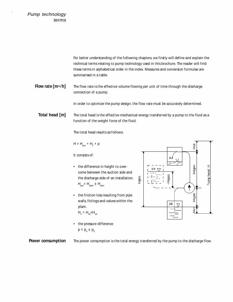
The total head is the ef fect ive mechanical energy t ransferred by a pump to the f luid as a
funct ion of the weight force of the f luid.
The total head results as follows:
H = Hgeo + HV + p
It consists of :
• the dif ference in height to over-
come between the suct ion side and
the discharge side of an installat ion.
Hgeo= Hdgeo ± Hsgeo
• the f rict ion loss result ing f rom pipe
walls, f it t ings and valves within the
plant .
HV = HVS+HVd
• the pressure dif ference
p = pA ± pE
The power consumpt ion is the total energy t ransferred by the pump to the discharge f low.
Flow rate [m≈/h]
Total head [m]
Power consumption
Pump technologyterms
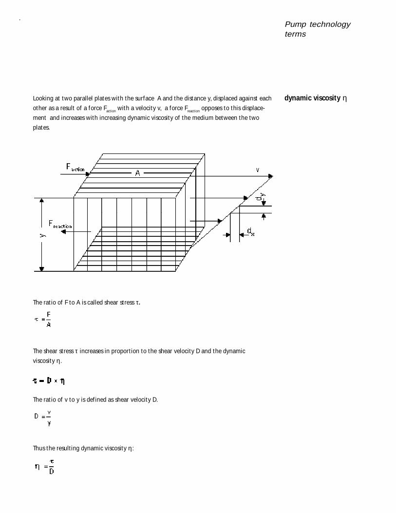
Looking at two parallel plates with the surface A and the distance y, displaced against each
other as a result of a force Fact ion with a velocity v, a force Freact ion opposes to this displace-
ment and increases with increasing dynamic viscosity of the medium between the two
plates.
The rat io of F to A is called shear st ress τ.
The shear st ress τ increases in proport ion to the shear velocity D and the dynamic
viscosity η.
The rat io of v to y is def ined as shear velocity D.
Thus the result ing dynamic viscosity η:
dynamic viscosity η
Pump technologyterms
Thus, the dynamic viscosity η is a characterist ic parameter of the f luid concerned and
depends on the temperature. Therefore the viscosity is always indicated together with the
corresponding temperature.
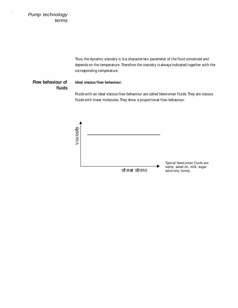
Ideal viscous flow behaviour:
Fluids with an ideal viscous f low behaviour are called Newtonian f luids. They are viscous
f luids with linear molecules. They show a proport ional f low behaviour.
Typical Newtonian f luids are:water, salad oil, milk, sugarsolut ions, honey.
Flow behaviour offluids
Pump technologyterms
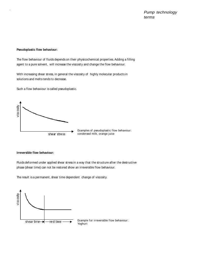
Pseudoplastic flow behaviour:
The f low behaviour of f luids depends on their physicochemical propert ies. Adding a f illing
agent to a pure solvent , will increase the viscosity and change the f low behaviour.
With increasing shear st ress, in general the viscosity of highly molecular products in
solut ions and melts tends to decrease.
Such a f low behaviour is called pseudoplast ic.
Examples of pseudoplast ic f low behaviour:condensed milk, orange juice
Irreversible flow behaviour:
Fluids deformed under applied shear st ress in a way that the st ructure af ter the destruct ive
phase (shear t ime) can not be restored show an irreversible f low behaviour.
The result is a permanent , shear t ime dependent change of viscosity.
Example f or irreversible f low behaviour:Yoghurt
Pump technologyterms
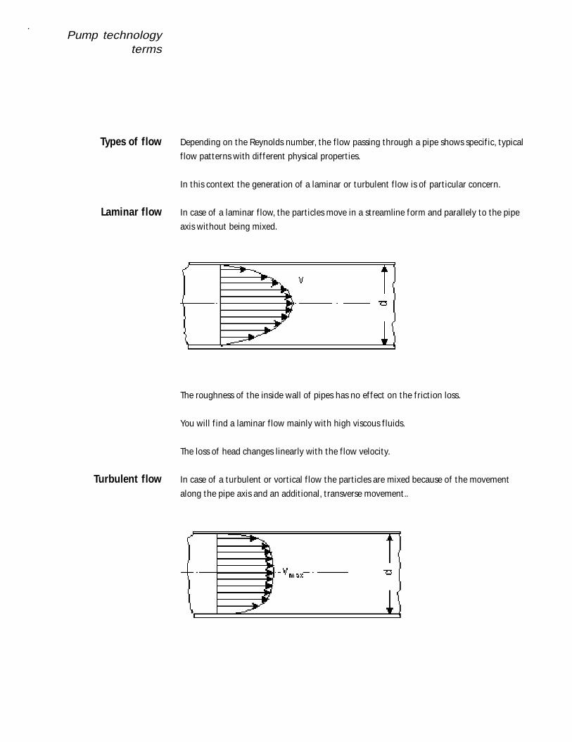
Depending on the Reynolds number, the f low passing through a pipe shows specif ic, typical
f low pat terns with dif ferent physical propert ies.
In this context the generat ion of a laminar or turbulent f low is of part icular concern.
In case of a laminar f low, the part icles move in a st reamline form and parallely to the pipe
axis without being mixed.
The roughness of the inside wall of pipes has no ef fect on the f rict ion loss.
You will f ind a laminar f low mainly with high viscous f luids.
The loss of head changes linearly with the f low velocity.
In case of a turbulent or vort ical f low the part icles are mixed because of the movement
along the pipe axis and an addit ional, t ransverse movement..
Types of flow
Laminar flow
Turbulent flow
Pump technologyterms
The roughness of the pipe inside has great ef fect on the f rict ion loss.
Turbulent f lows are mainly found with water or f luids similar to water.
The loss on pump head varies by square of the f low velocity.
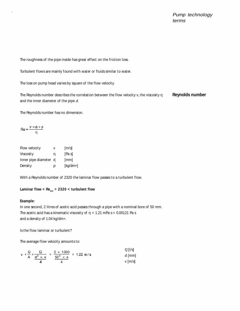
The Reynolds number describes the correlat ion between the f low velocity v, the viscosity ηand the inner diameter of the pipe d.
The Reynolds number has no dimension.
Flow velocity v [m/s]
Viscosity η [Pa s]
Inner pipe diameter di [mm]
Density ρ [kg/dm≈]
With a Reynolds number of 2320 the laminar f low passes to a turbulent f low.
Laminar flow < Rekrit = 2320 < turbulent flow
Example:
In one second, 2 lit res of acet ic acid passes through a pipe with a nominal bore of 50 mm.
The acet ic acid has a kinemat ic viscosity of η = 1.21 mPa s = 0.00121 Pa s
and a density of 1.04 kg/dm≈.
Is the f low laminar or turbulent?
The average f low velocity amounts to:
Reynolds number
Q [l/s]
d [mm]
v [m/s]
Pump technologyterms
Thus the calculated Reynolds number is:
The Reynolds number exceeds the crit ical Reynolds number Rekrit=2320. The f low is turbu-
lent .
NPSH is the abbreviat ion for Net Posit ive Suct ion Head
Besides the f low rate Q and the pump head H, the NPSH value is one of the most important
characterist ic parameter of a centrifugal pump.
The NPSH value of the pump depends on the design and speed of the pump. The higher the
speed of the pump, the higher the NPSH value will be.
The NPSH value is measured on a pump test stand and cannot be modif ied without sup-
plementary means.
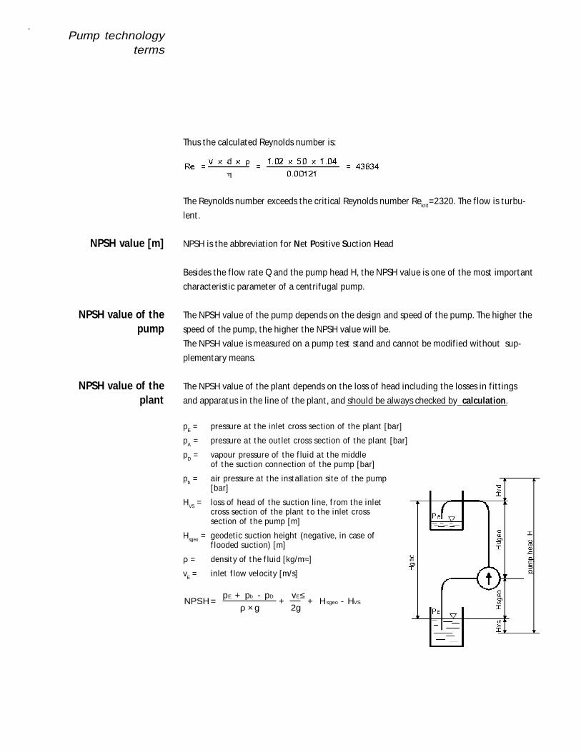
The NPSH value of the plant depends on the loss of head including the losses in f it t ings
and apparatus in the line of the plant , and should be always checked by calculation.
pE = pressure at t he inlet cross section of the plant [bar]
pA = pressure at t he out let cross section of t he plant [bar]
pD = vapour pressure of the f luid at t he middleof t he suction connection of t he pump [bar]
pb = air pressure at t he installation site of t he pump[bar]
HVS = loss of head of t he suction line, f rom the inletcross section of the plant t o t he inlet crosssection of t he pump [m]
Hsgeo = geodet ic suction height (negative, in case off looded suction) [m]
ρ = densit y of t he f luid [kg/m≈]
vE = inlet f low velocity [m/s]
NPSH= p + p - p
g+
v ≤2g
+ H - H E b D E
sgeo VSρ ×
NPSH value [m]
NPSH value of thepump
NPSH value of theplant
Pump technologyterms
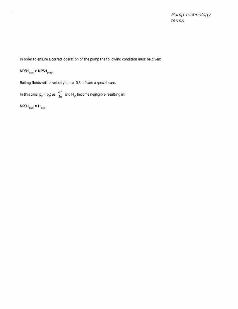
In order to ensure a correct operat ion of the pump the following condit ion must be given:
NPSHplant > NPSHpump
Boiling f luids with a velocity up to 0,3 m/s are a special case.
In this case: pE = pD; as v2g
E2
and HVS become negligible result ing in:
NPSHplant = Hsgeo
Loss of headcalculation
Already during design of the plant and piping layout in f ront of and behind the pump,
losses can be limited when considering:
• the pipe diameter is suf f icient ly dimensioned,
• less f it t ings are used,
• f it t ings with low f rict ion loss are selected,
• short pipe runs are planned.
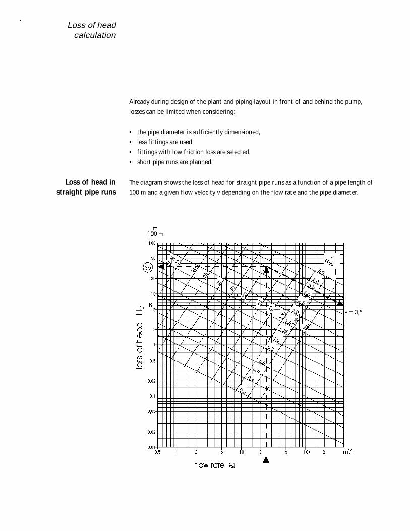
The diagram shows the loss of head for st raight pipe runs as a funct ion of a pipe length of
100 m and a given f low velocity v depending on the f low rate and the pipe diameter.
Loss of head instraight pipe runs
Loss of headcalculation
Example:
Flow rate Q = 25 m≈/h
Pipe diameter d = 50 mm
From the diagram results:
Flow velocity v = 3.5 m/s
Loss of head HV = 35 m/100 m
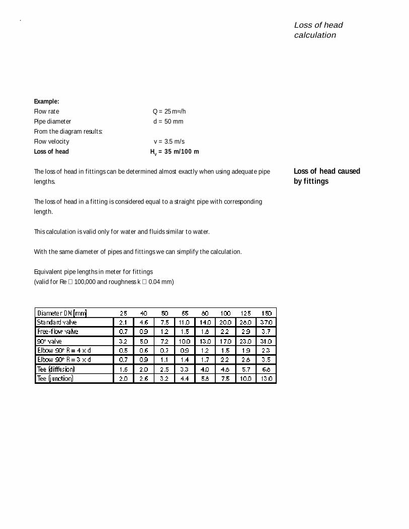
The loss of head in f it t ings can be determined almost exact ly when using adequate pipe
lengths.
The loss of head in a f it t ing is considered equal to a st raight pipe with corresponding
length.
This calculat ion is valid only for water and f luids similar to water.
With the same diameter of pipes and f it t ings we can simplify the calculat ion.
Equivalent pipe lengths in meter for f it t ings
(valid for Re ⊕ 100,000 and roughness k ∪ 0.04 mm)
Loss of head causedby fittings
Loss of headcalculation
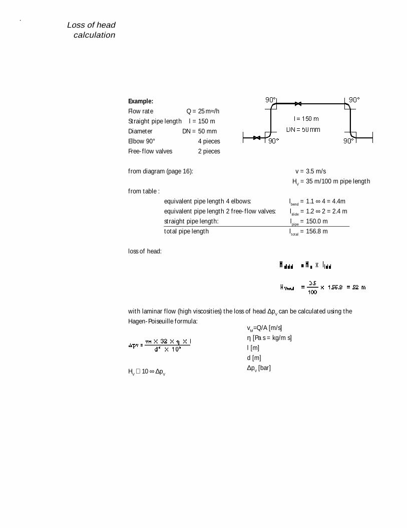
Example:
Flow rate Q = 25 m≈/h
Straight pipe length l = 150 m
Diameter DN = 50 mm
Elbow 90° 4 pieces
Free- f low valves 2 pieces
from diagram (page 16): v = 3.5 m/s
HV = 35 m/100 m pipe length
from table :
equivalent pipe length 4 elbows: lbend = 1.1 ∞ 4 = 4.4m
equivalent pipe length 2 f ree- f low valves: lslide = 1.2 ∞ 2 = 2.4 m
straight pipe length: lpipe = 150.0 m
total pipe length ltotal = 156.8 m
loss of head:
with laminar f low (high viscosit ies) the loss of head ∆pV can be calculated using the
Hagen-Poiseuille formula:
HV ∪ 10 ∞ ∆pV
vM=Q/A [m/s]
η [Pa s = kg/m s]
l [m]
d [m]
∆pV [bar]
Pump typeselection
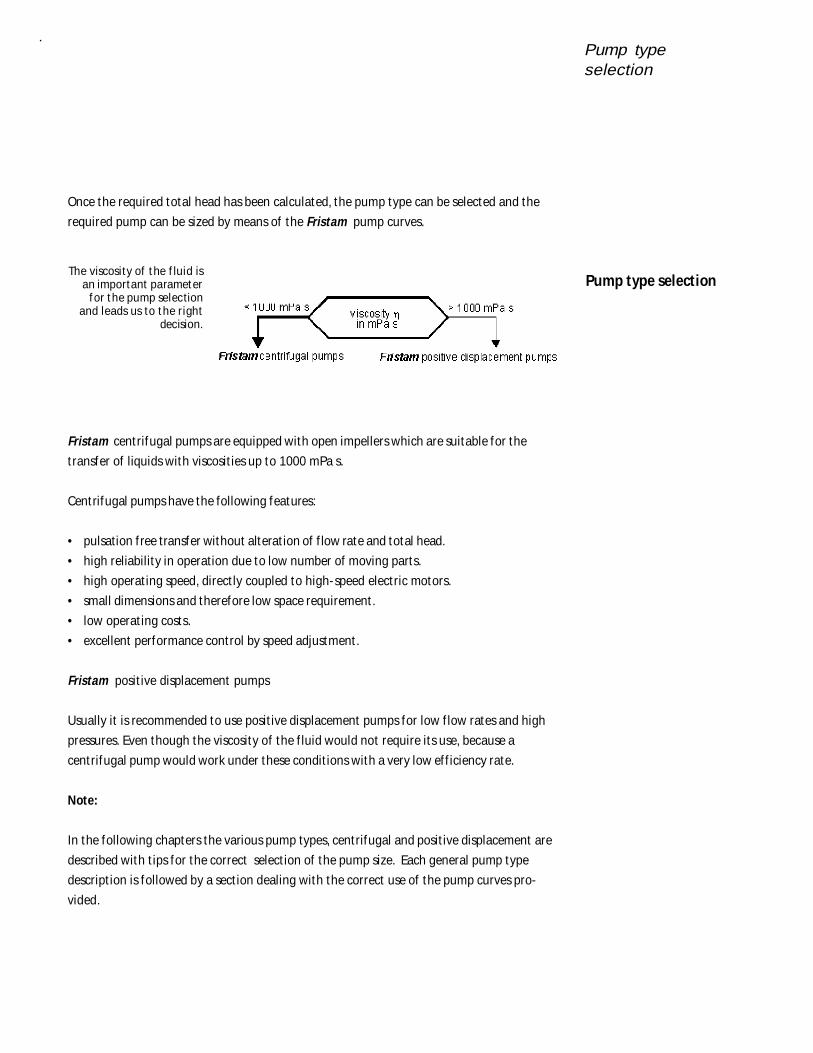
Once the required total head has been calculated, the pump type can be selected and the
required pump can be sized by means of the Fristam pump curves.
The viscosity of t he f luid isan important parameter
f or t he pump selectionand leads us to t he right
decision.
Fristam centrifugal pumps are equipped with open impellers which are suitable for the
transfer of liquids with viscosit ies up to 1000 mPa s.
Centrifugal pumps have the following features:
• pulsation f ree transfer without alterat ion of f low rate and total head.
• high reliability in operation due to low number of moving parts.
• high operat ing speed, direct ly coupled to high-speed electric motors.
• small dimensions and therefore low space requirement .
• low operat ing costs.
• excellent performance control by speed adjustment .
Fristam posit ive displacement pumps
Usually it is recommended to use posit ive displacement pumps for low f low rates and high
pressures. Even though the viscosity of the f luid would not require its use, because a
centrifugal pump would work under these condit ions with a very low ef f iciency rate.
Note:
In the following chapters the various pump types, centrifugal and posit ive displacement are
described with t ips for the correct select ion of the pump size. Each general pump type
descript ion is followed by a sect ion dealing with the correct use of the pump curves pro-
vided.
Pump type selection
Centrifugal pumps
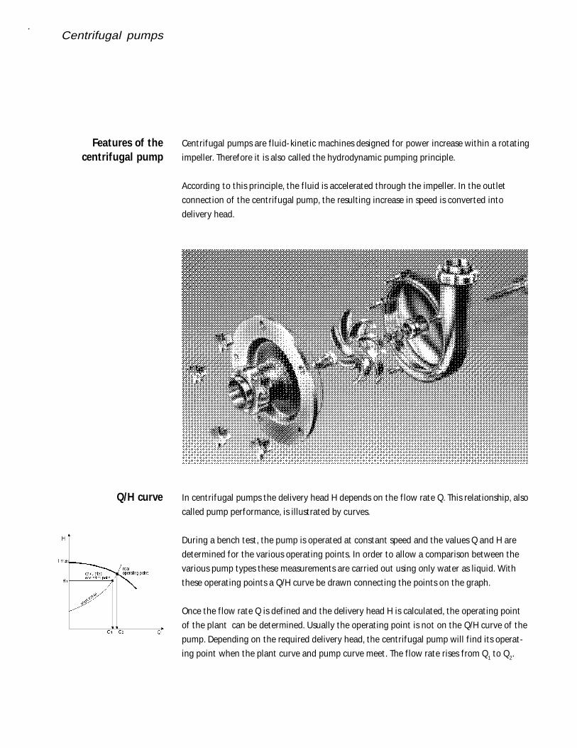
Centrifugal pumps are f luid- kinet ic machines designed for power increase within a rotat ing
impeller. Therefore it is also called the hydrodynamic pumping principle.
According to this principle, the f luid is accelerated through the impeller. In the out let
connect ion of the centrifugal pump, the result ing increase in speed is converted into
delivery head.
In centrifugal pumps the delivery head H depends on the f low rate Q. This relat ionship, also
called pump performance, is illust rated by curves.
During a bench test , the pump is operated at constant speed and the values Q and H are
determined for the various operat ing points. In order to allow a comparison between the
various pump types these measurements are carried out using only water as liquid. With
these operat ing points a Q/H curve be drawn connect ing the points on the graph.
Once the f low rate Q is def ined and the delivery head H is calculated, the operat ing point
of the plant can be determined. Usually the operat ing point is not on the Q/H curve of the
pump. Depending on the required delivery head, the centrifugal pump will f ind its operat-
ing point when the plant curve and pump curve meet . The f low rate rises f rom Q1 to Q2.
Features of thecentrifugal pump
Q/H curve
Centrifugal pumps
The required operat ing point is obtained by adapt ing the pump to the specif ied operat ing
condit ions.
This can be done by the following act ions:
• throt t ling the f low
• correct ing the diameter of the impeller
• Adjust ing the speed of the drive
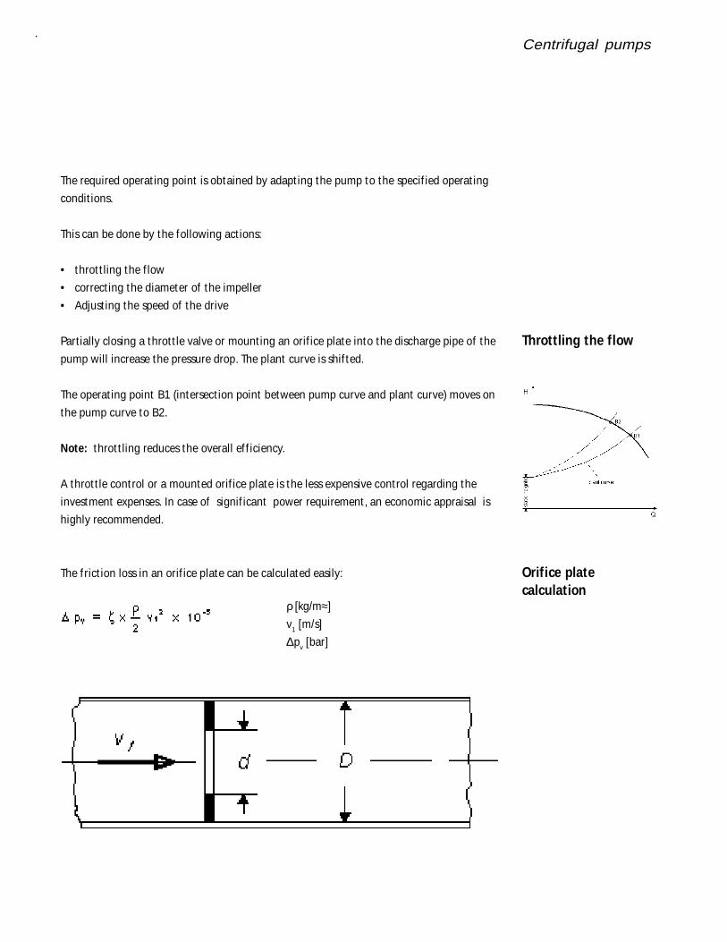
Partially closing a throt t le valve or mount ing an orif ice plate into the discharge pipe of the
pump will increase the pressure drop. The plant curve is shif ted.
The operat ing point B1 (intersect ion point between pump curve and plant curve) moves on
the pump curve to B2.
Note: throt t ling reduces the overall ef f iciency.
A throt t le control or a mounted orif ice plate is the less expensive control regarding the
investment expenses. In case of signif icant power requirement , an economic appraisal is
highly recommended.
The f rict ion loss in an orif ice plate can be calculated easily:
ρ [kg/m≈]
v1 [m/s]
∆pv [bar]
Throttling the flow
Orifice platecalculation
Centrifugal pumps
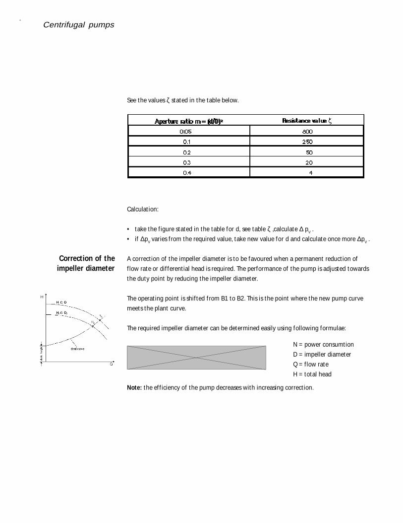
See the values ζ stated in the table below.
Calculat ion:
• take the f igure stated in the table for d, see table ζ ,calculate ∆ pV .
• if ∆pV varies f rom the required value, take new value for d and calculate once more ∆pV .
A correct ion of the impeller diameter is to be favoured when a permanent reduct ion of
f low rate or dif ferent ial head is required. The performance of the pump is adjusted towards
the duty point by reducing the impeller diameter.
The operat ing point is shif ted f rom B1 to B2. This is the point where the new pump curve
meets the plant curve.
The required impeller diameter can be determined easily using following formulae:
Note: the ef f iciency of the pump decreases with increasing correct ion.
Correction of theimpeller diameter
N = power consumt ion
D = impeller diameter
Q = f low rate
H = total head
Centrifugal pumps
Pump speed control
Parallely connectedpumps
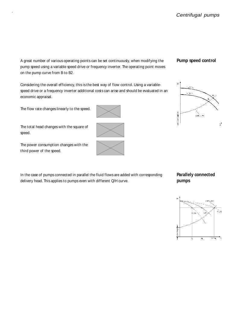
A great number of various operat ing points can be set cont inuously, when modifying the
pump speed using a variable speed drive or f requency inverter. The operat ing point moves
on the pump curve f rom B to B2.
Considering the overall ef f iciency, this is the best way of f low control. Using a variable-
speed drive or a f requency inverter addit ional costs can arise and should be evaluated in an
economic appraisal.
The f low rate changes linearly to the speed.
The total head changes with the square of
speed.
The power consumpt ion changes with the
third power of the speed.
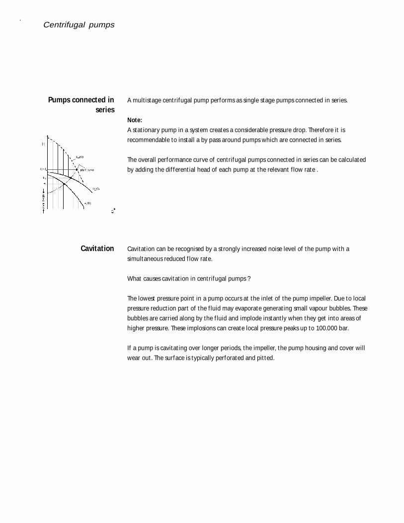
In the case of pumps connected in parallel the f luid f lows are added with corresponding
delivery head. This applies to pumps even with dif ferent Q/H curve.
Centrifugal pumps
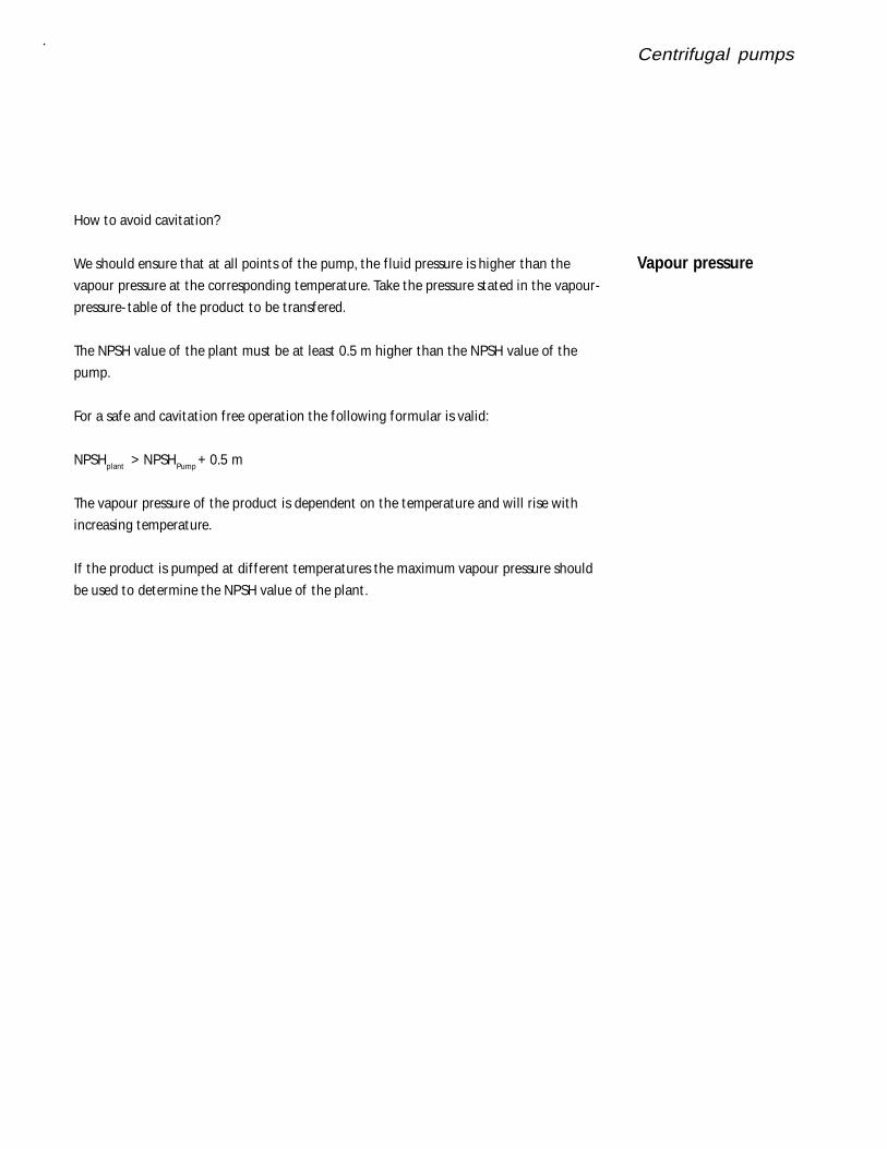
A mult istage centrifugal pump performs as single stage pumps connected in series.
Note:
A stat ionary pump in a system creates a considerable pressure drop. Therefore it is
recommendable to install a by pass around pumps which are connected in series.
The overall performance curve of centrifugal pumps connected in series can be calculated
by adding the dif ferent ial head of each pump at the relevant f low rate .
Cavitat ion can be recognised by a st rongly increased noise level of the pump with a
simultaneous reduced f low rate.
What causes cavitat ion in centrifugal pumps ?
The lowest pressure point in a pump occurs at the inlet of the pump impeller. Due to local
pressure reduct ion part of the f luid may evaporate generat ing small vapour bubbles. These
bubbles are carried along by the f luid and implode instant ly when they get into areas of
higher pressure. These implosions can create local pressure peaks up to 100.000 bar.
If a pump is cavitat ing over longer periods, the impeller, the pump housing and cover will
wear out . The surface is typically perforated and pit ted.
Pumps connected inseries
Cavitation
Centrifugal pumps
How to avoid cavitat ion?
We should ensure that at all points of the pump, the f luid pressure is higher than the
vapour pressure at the corresponding temperature. Take the pressure stated in the vapour-
pressure- table of the product to be t ransfered.
The NPSH value of the plant must be at least 0.5 m higher than the NPSH value of the
pump.
For a safe and cavitat ion f ree operat ion the following formular is valid:
NPSHplant > NPSHPump + 0.5 m
The vapour pressure of the product is dependent on the temperature and will rise with
increasing temperature.
If the product is pumped at dif ferent temperatures the maximum vapour pressure should
be used to determine the NPSH value of the plant .
Vapour pressure
Centrifugal pumps
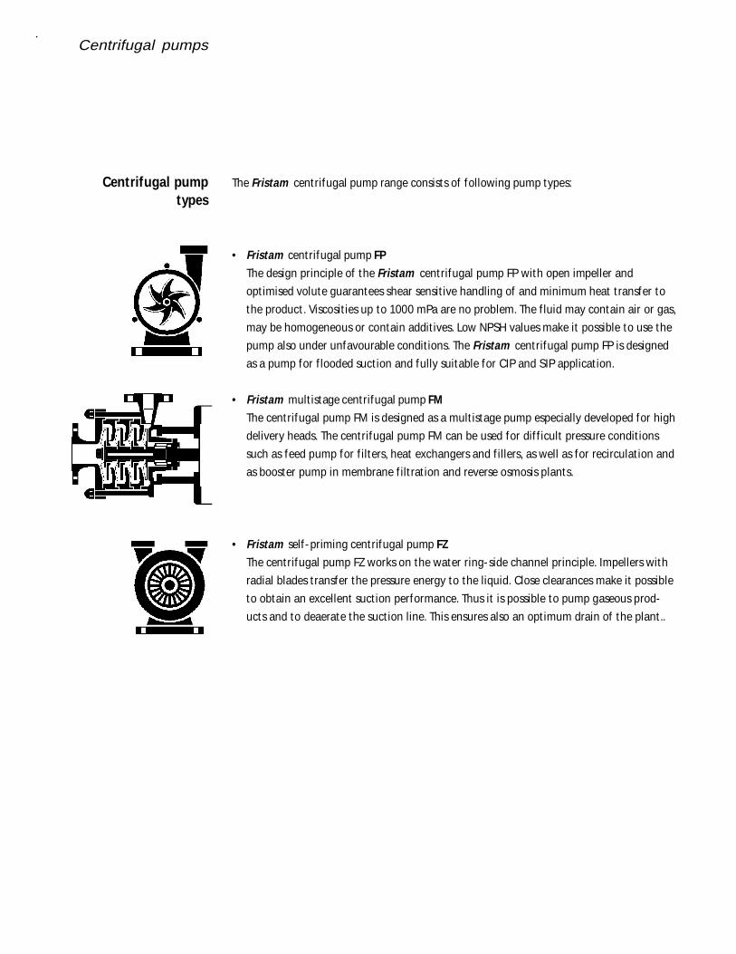
The Fristam centrifugal pump range consists of following pump types:
• Fristam centrifugal pump FP
The design principle of the Fristam centrifugal pump FP with open impeller and
opt imised volute guarantees shear sensit ive handling of and minimum heat t ransfer to
the product . Viscosit ies up to 1000 mPa are no problem. The f luid may contain air or gas,
may be homogeneous or contain addit ives. Low NPSH values make it possible to use the
pump also under unfavourable condit ions. The Fristam centrifugal pump FP is designed
as a pump for f looded suct ion and fully suitable for CIP and SIP applicat ion.
• Fristam mult istage centrifugal pump FM
The centrifugal pump FM is designed as a mult istage pump especially developed for high
delivery heads. The centrifugal pump FM can be used for dif f icult pressure condit ions
such as feed pump for f ilters, heat exchangers and f illers, as well as for recirculat ion and
as booster pump in membrane f ilt rat ion and reverse osmosis plants.
• Fristam self - priming centrifugal pump FZ
The centrifugal pump FZ works on the water ring-side channel principle. Impellers with
radial blades t ransfer the pressure energy to the liquid. Close clearances make it possible
to obtain an excellent suct ion performance. Thus it is possible to pump gaseous prod-
ucts and to deaerate the suct ion line. This ensures also an opt imum drain of the plant ..
Centrifugal pumptypes
Centrifugal pumps
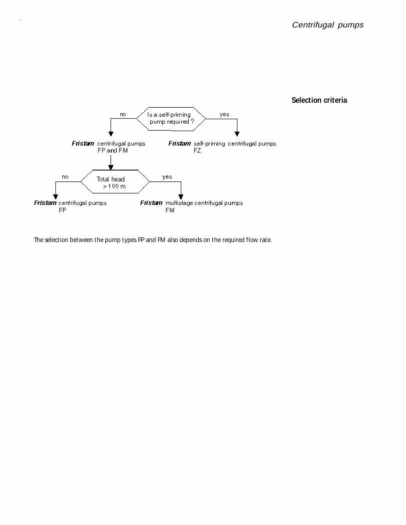
The select ion between the pump types FP and FM also depends on the required f low rate.
Selection criteria
Centrifugal pumps
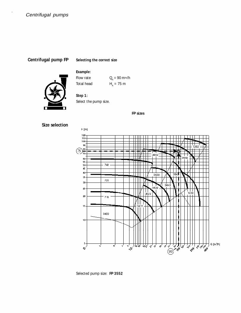
Selecting the correct size
Example:
Flow rate QA = 90 m≈/h
Total head HA = 75 m
Step 1:
Select the pump size.
FP sizes
Selected pump size: FP 3552
Centrifugal pump FP
Size selection
Centrifugal pumps
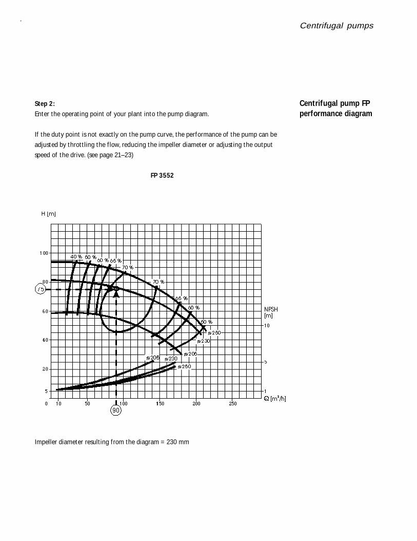
Step 2:
Enter the operat ing point of your plant into the pump diagram.
If the duty point is not exact ly on the pump curve, the performance of the pump can be
adjusted by throt t ling the f low, reducing the impeller diameter or adjust ing the output
speed of the drive. (see page 21–23)
FP 3552
Impeller diameter result ing f rom the diagram = 230 mm
Centrifugal pump FPperformance diagram
Centrifugal pumps
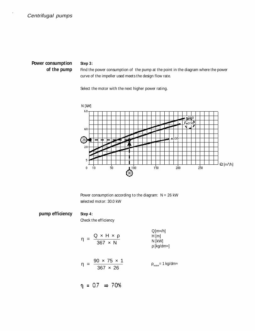
Step 3:
Find the power consumpt ion of the pump at the point in the diagram where the power
curve of the impeller used meets the design f low rate.
Select the motor with the next higher power rat ing.
Power consumpt ion according to the diagram: N = 26 kW
selected motor: 30.0 kW
Step 4:
Check the ef f iciency
η ρ =
Q H N
× ×
×367
η = 90 75 1
367 26
× ××
ρwater= 1 kg/dm≈
Power consumptionof the pump
pump efficiency
Q [m≈/h]H [m]N [kW]ρ [kg/dm≈]
Centrifugal pumps
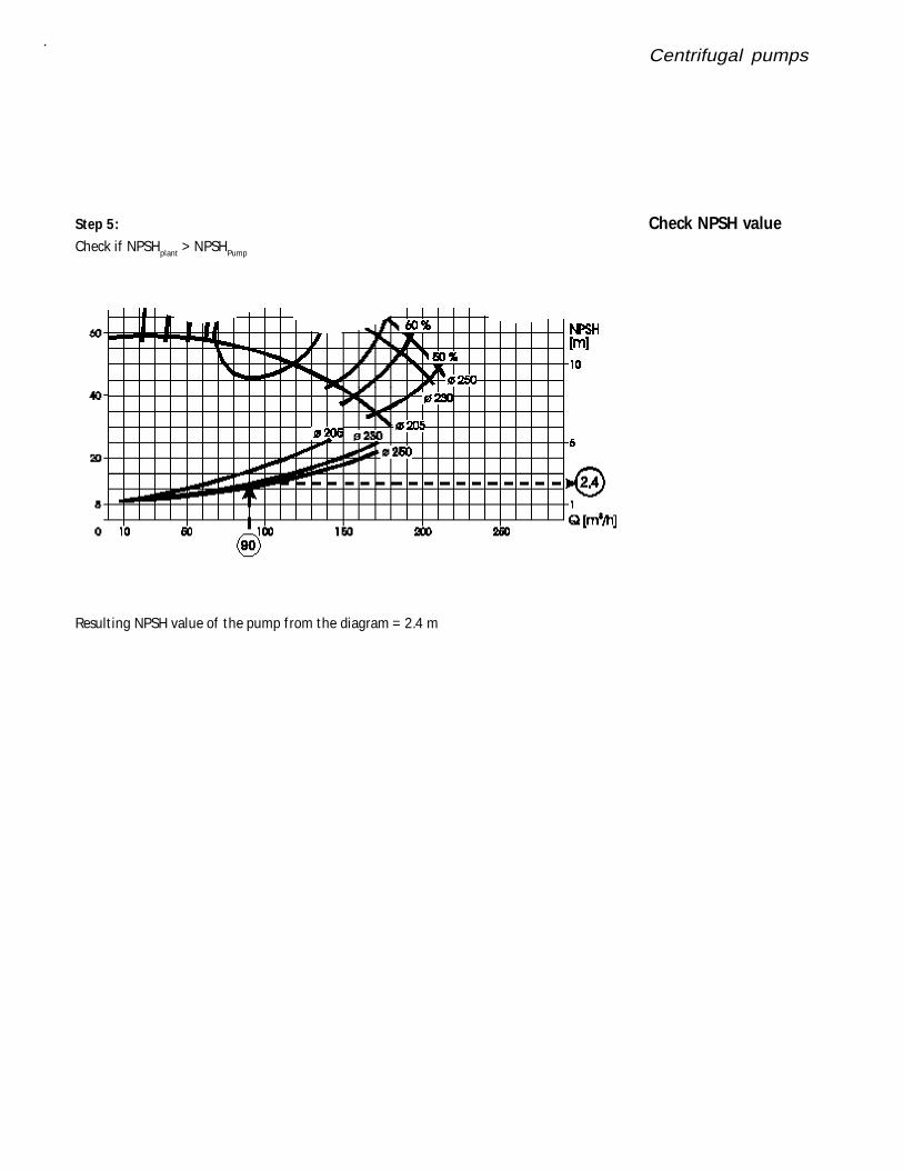
Step 5:
Check if NPSHplant > NPSHPump
Result ing NPSH value of the pump f rom the diagram = 2.4 m
Check NPSH value
Centrifugal pumps
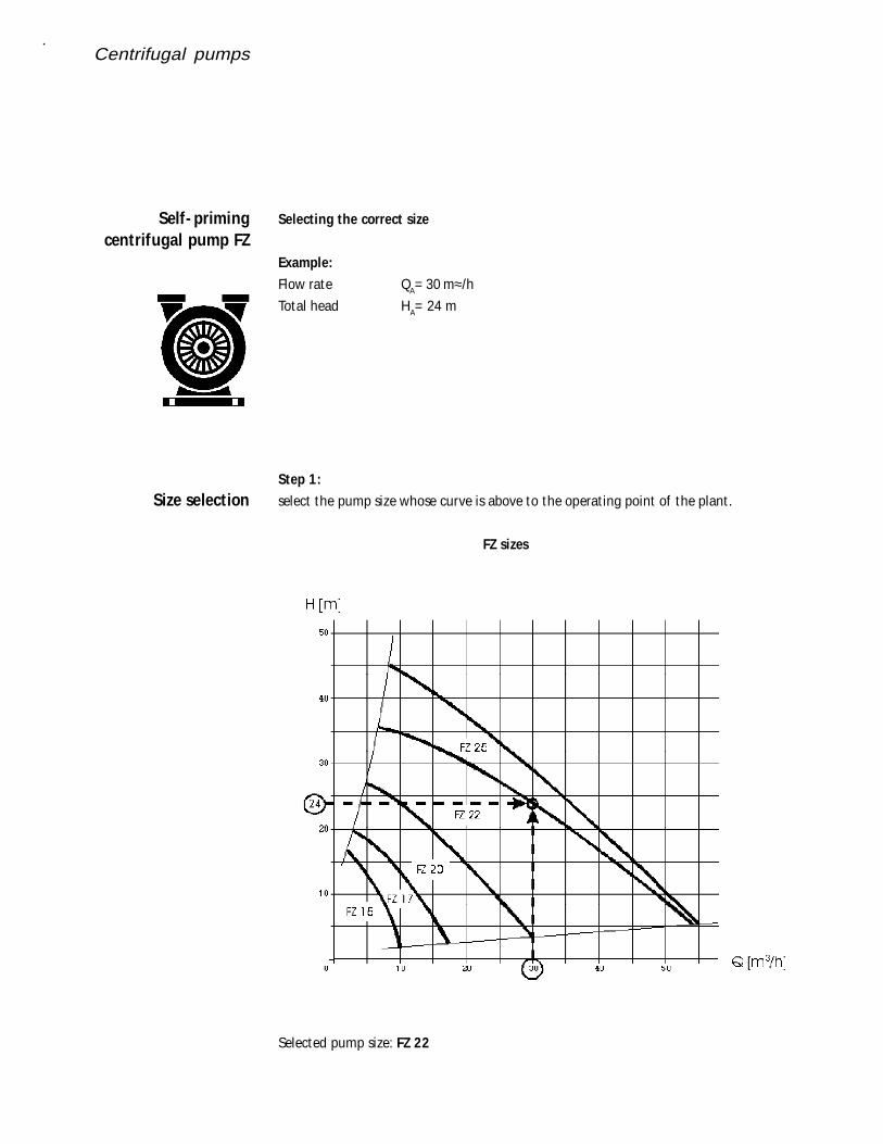
Selecting the correct size
Example:
Flow rate QA= 30 m≈/h
Total head HA= 24 m
Step 1:
select the pump size whose curve is above to the operat ing point of the plant .
FZ sizes
Selected pump size: FZ 22
Self- primingcentrifugal pump FZ
Size selection
Centrifugal pumps
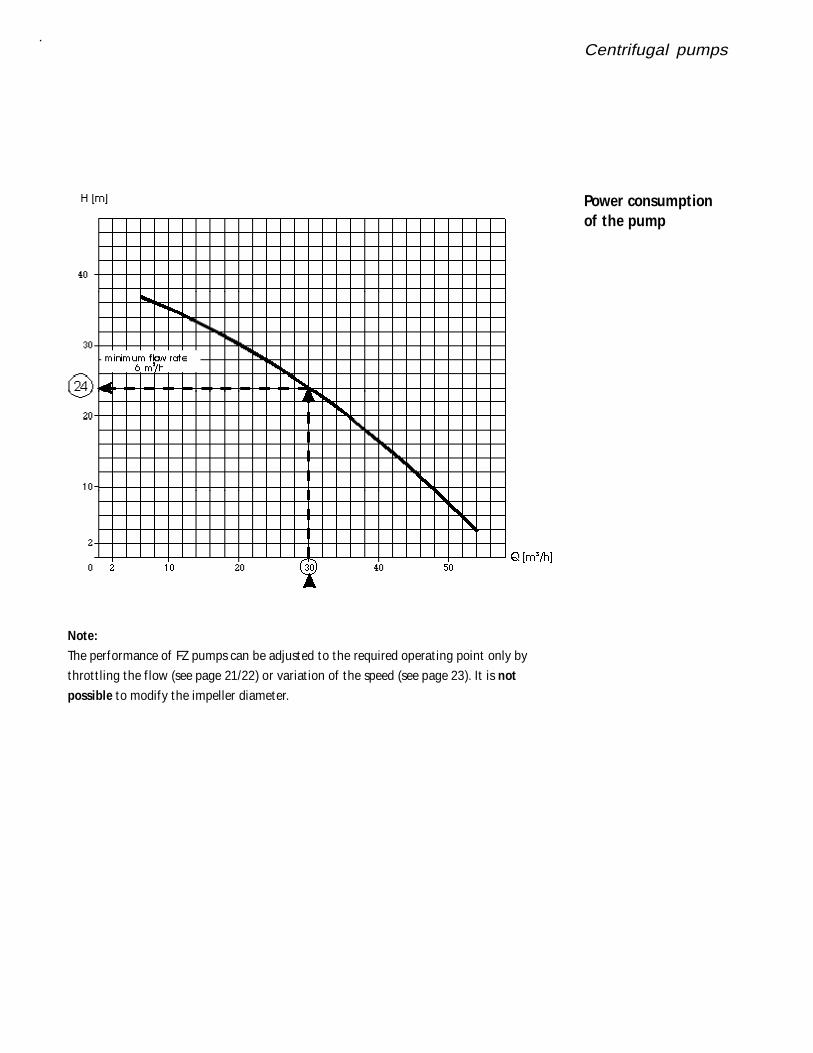
Note:
The performance of FZ pumps can be adjusted to the required operat ing point only by
throt t ling the f low (see page 21/22) or variat ion of the speed (see page 23). It is not
possible to modify the impeller diameter.
Power consumptionof the pump
Centrifugal pumps
Multistagecentrifugal pump FM
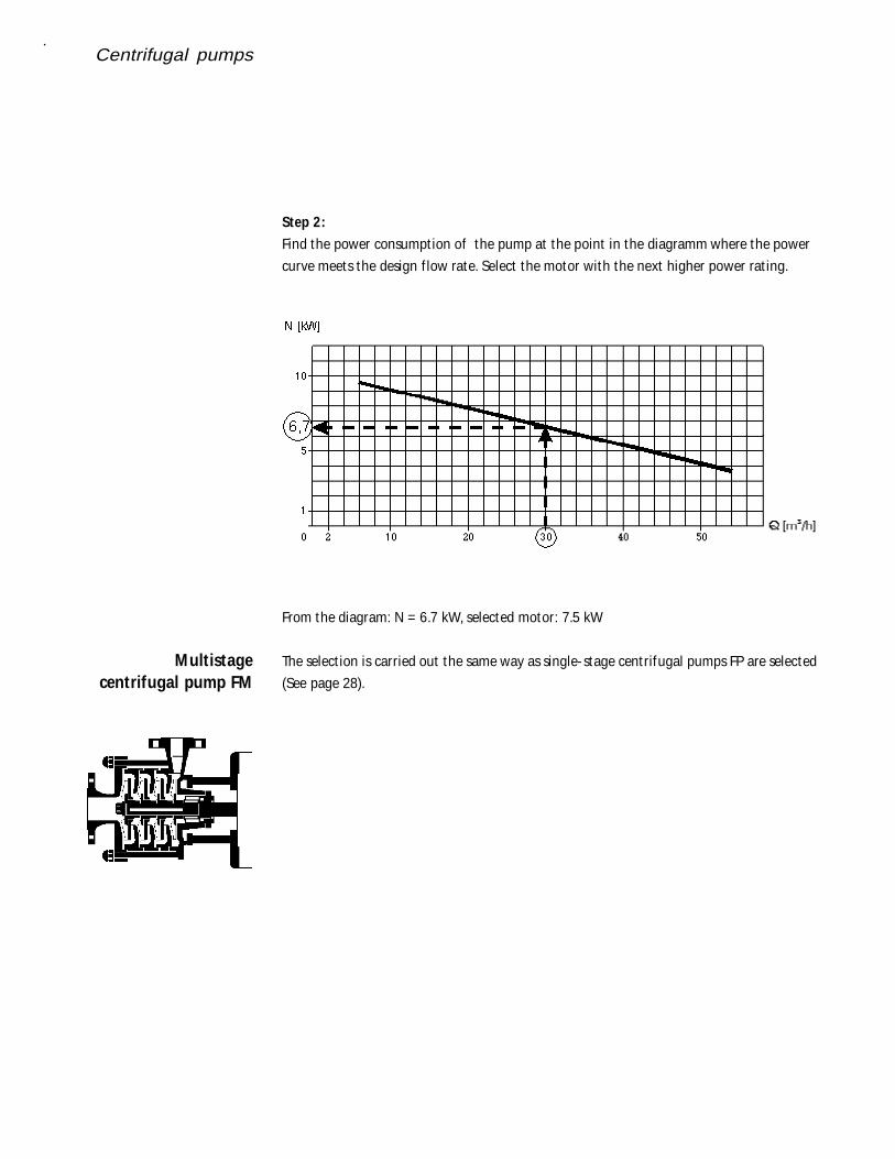
Step 2:
Find the power consumpt ion of the pump at the point in the diagramm where the power
curve meets the design f low rate. Select the motor with the next higher power rat ing.
From the diagram: N = 6.7 kW, selected motor: 7.5 kW
The select ion is carried out the same way as single-stage centrifugal pumps FP are selected
(See page 28).
Positivedisplacementpumps
Posit ive displacement pumps are hydrostat ic machines. They operate with a posit ive t ransfer
and should not work against a closed system.
All rotary pumps are designed af ter the same principle. Two rotors are arranged on parallel
shaf ts and driven by an external synchronous gear box.
The rotors rotate in opposite direct ions to each other. Small radial and axial clearences assure
that they have no contact with each other, or the pump body. The rotors are designed to
form a barrier between the suct ion and pressure side of the pump in any posit ion. The
sealing is only maintained by narrow gaps. There are no addit ional seals or valves.
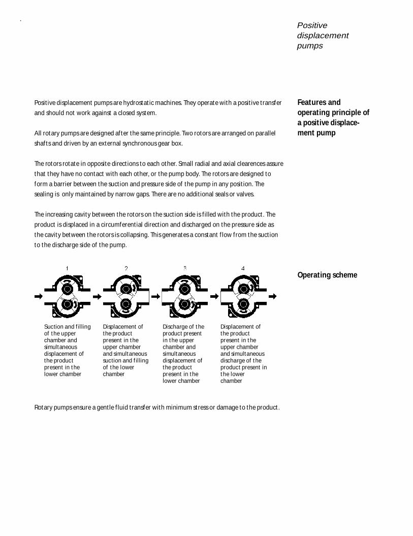
The increasing cavity between the rotors on the suct ion side is f illed with the product . The
product is displaced in a circumferent ial direct ion and discharged on the pressure side as
the cavity between the rotors is collapsing. This generates a constant f low f rom the suct ion
to the discharge side of the pump.
Rotary pumps ensure a gent le f luid t ransfer with minimum stress or damage to the product .
Features andoperating principle ofa positive displace-ment pump
Operating scheme
Suction and f il lingof t he upperchamber andsimultaneousdisplacement ofthe productpresent in t helower chamber
Displacement ofthe productpresent in t heupper chamberand simultaneoussuction and f il lingof t he lowerchamber
Discharge of t heproduct presentin t he upperchamber andsimultaneousdisplacement ofthe productpresent in t helower chamber
Displacement ofthe productpresent in t heupper chamberand simultaneousdischarge of t heproduct present int he lowerchamber
Positivedisplacement
pumps
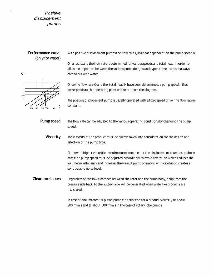
With posit ive displacement pumps the f low rate Q is linear dependent on the pump speed n.
On a test stand the f low rate is determined for various speeds and total head. In order to
allow a comparison between the various pump designs and types, these tests are always
carried out with water.
Once the f low rate Q and the total head H have been determined, a pump speed n that
corresponds to this operat ing point will result f rom the diagram.
The posit ive displacement pump is usually operated with a f ixed speed drive. The f low rate is
constant .
The f low rate can be adjusted to the various operat ing condit ions by changing the pump
speed.
The viscosity of the product must be always taken into considerat ion for the design and
select ion of the pump type.
Fluids with higher viscosit ies require more t ime to enter the displacement chamber. In those
cases the pump speed must be adjusted accordingly to avoid cavitat ion which reduces the
volumetric ef f iciency and increases the wear. A pump operat ing with cavitation creates a
considerable noise level.
Regardless of the low clearance between the rotor and the pump body, a slip f rom the
pressure side back to the suct ion side will be generated when waterlike products are
transfered.
In case of circumferent ial piston pumps the slip stops at a product viscosity of about
200 mPa s and at about 500 mPa s in the case of rotary lobe pumps.
Performance curve(only for water)
Pump speed
Viscosity
Clearance losses
Positivedisplacementpumps
Fristam supplies two different positive diplacement pump designs depending on the applica-
tion.
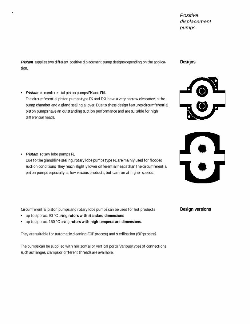
• Fristam circumferent ial piston pumps FK and FKL
The circumferent ial piston pumps type FK and FKL have a very narrow clearance in the
pump chamber and a gland sealing allover. Due to these design features circumferent ial
piston pumps have an outstanding suct ion performance and are suitable for high
dif ferent ial heads.
• Fristam rotary lobe pumps FL
Due to the gland/line sealing, rotary lobe pumps type FL are mainly used for f looded
suct ion condit ions. They reach slight ly lower dif ferent ial heads than the circumferent ial
piston pumps especially at low viscous products, but can run at higher speeds.
Circumferent ial piston pumps and rotary lobe pumps can be used for hot products
• up to approx. 90 °C using rotors with standard dimensions
• up to approx. 150 °C using rotors with high temperature dimensions.
They are suitable for automat ic cleaning (CIP process) and sterilisat ion (SIP process).
The pumps can be supplied with horizontal or vert ical ports. Various types of connect ions
such as f langes, clamps or dif ferent threads are available.
Designs
Design versions
Positivedisplacement
pumps
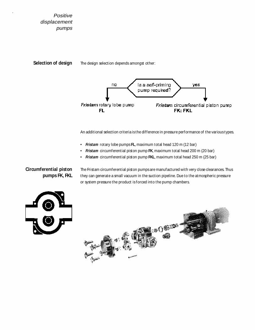
The design select ion depends amongst other:
An addit ional select ion criteria is the dif ference in pressure performance of the various types.
• Fristam rotary lobe pumps FL, maximum total head 120 m (12 bar)
• Fristam circumferent ial piston pump FK, maximum total head 200 m (20 bar)
• Fristam circumferent ial piston pump FKL, maximum total head 250 m (25 bar)
The Fristam circumferent ial piston pumps are manufactured with very close clearances. Thus
they can generate a small vacuum in the suct ion pipeline. Due to the atmospheric pressure
or system pressure the product is forced into the pump chambers.
Selection of design
Circumferential pistonpumps FK, FKL
Positivedisplacementpumps
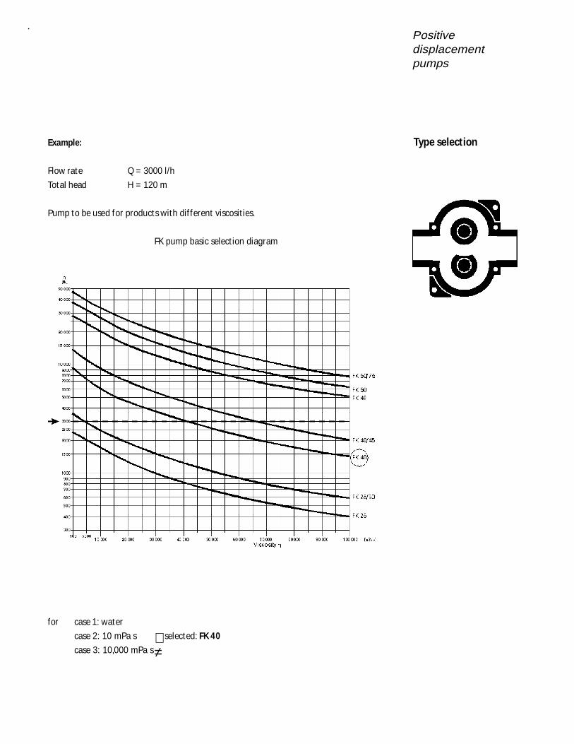
Example:
Flow rate Q = 3000 l/h
Total head H = 120 m
Pump to be used for products with dif ferent viscosit ies.
FK pump basic select ion diagram
for case 1: water
case 2: 10 mPa s selected: FK 40
case 3: 10,000 mPa s≠
Type selection
Positivedisplacement
pumps
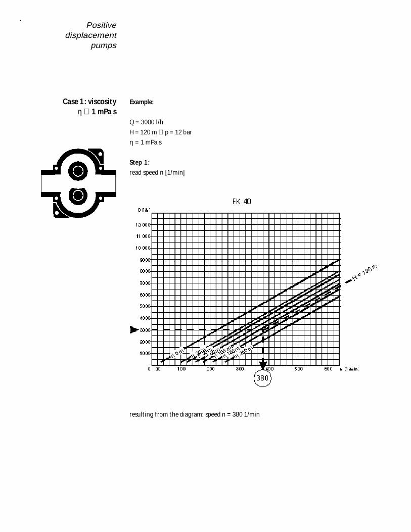
Example:
Q = 3000 l/h
H = 120 m ∪ p = 12 bar
η = 1 mPa s
Step 1:
read speed n [1/min]
result ing f rom the diagram: speed n = 380 1/min
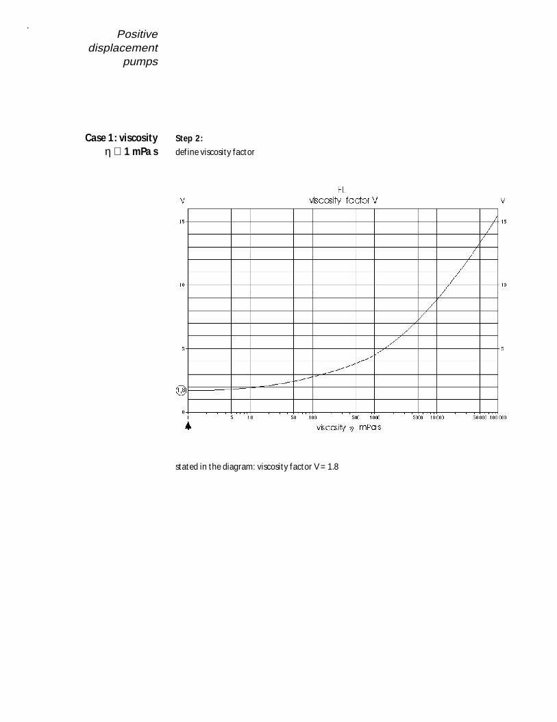
Case 1: viscosityη ∪ 1 mPa s
Positivedisplacementpumps
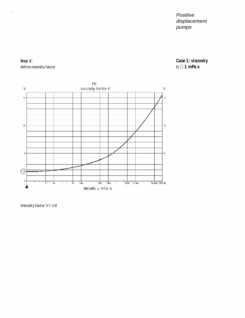
Step 2:
def ine viscosity factor
Viscosity factor V = 1.8
Case 1: viscosityη ∪ 1 mPa s
Positivedisplacement
pumps
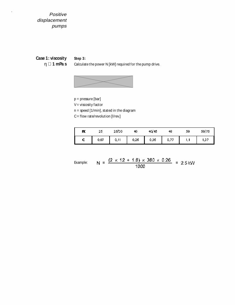
Step 3:
Calculate the power N [kW] required for the pump drive.
p = pressure [bar]
V = viscosity factor
n = speed [1/min], stated in the diagram
C = f low rate/revolut ion [l/rev.]
Example:
Case 1: viscosityη ∪ 1 mPa s
Positivedisplacementpumps
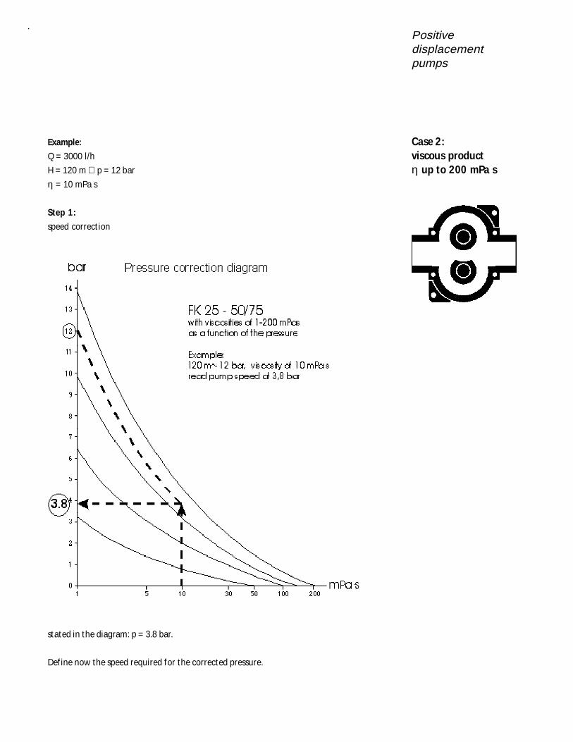
Example:
Q = 3000 l/h
H = 120 m ∪ p = 12 bar
η = 10 mPa s
Step 1:
speed correct ion
stated in the diagram: p = 3.8 bar.
Def ine now the speed required for the corrected pressure.
Case 2:viscous productη up to 200 mPa s
Positivedisplacement
pumps
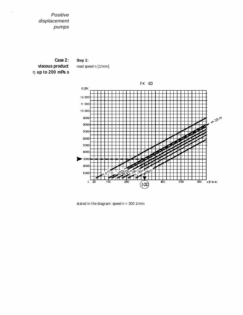
Step 2:
read speed n [1/min]
stated in the diagram: speed n = 300 1/min
Case 2:viscous product
η up to 200 mPa s
Positivedisplacementpumps
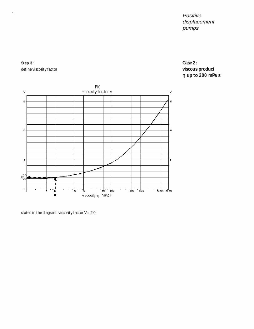
Step 3:
def ine viscosity factor
stated in the diagram: viscosity factor V = 2.0
Case 2:viscous productη up to 200 mPa s

Positivedisplacement
pumps
Step 3:
Calculate power consumpt ion N [kW] to select the pump drive.
N =(2 p + V) n C
1000× × ×
p = pressure in bar ∪ H/10
V = viscosity factor
n = speed with H = 38 m
C = f low rate/revolut ion [l/rev.]
Example :
Case 2:viscous product
η up to 200 mPa s
Positivedisplacementpumps
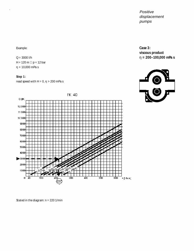
Example:
Q = 3000 l/h
H = 120 m ∪ p = 12 bar
η = 10,000 mPa s
Step 1:
read speed with H = 0, η > 200 mPa s
Stated in the diagram: n = 220 1/min
Case 3:viscous productη = 200–100,000 mPa s
Positivedisplacement
pumps
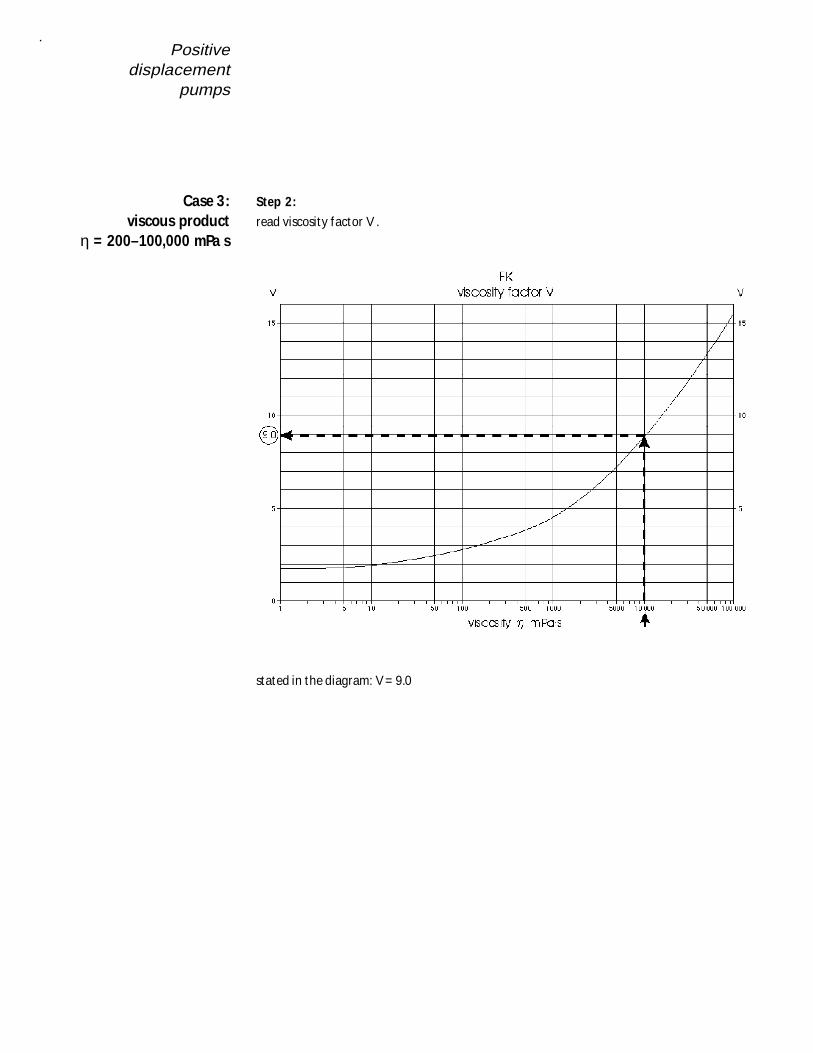
Step 2:
read viscosity factor V .
stated in the diagram: V = 9.0
Case 3:viscous product
η = 200–100,000 mPa s
Positivedisplacementpumps
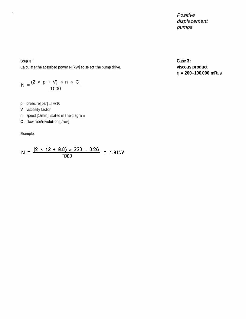
Step 3:
Calculate the absorbed power N [kW] to select the pump drive.
N =(2 p + V) n C
1000× × ×
p = pressure [bar] ∪ H/10
V = viscosity factor
n = speed [1/min], stated in the diagram
C = f low rate/revolut ion [l/rev.]
Example:
Case 3:viscous productη = 200–100,000 mPa s
Positivedisplacement
pumps
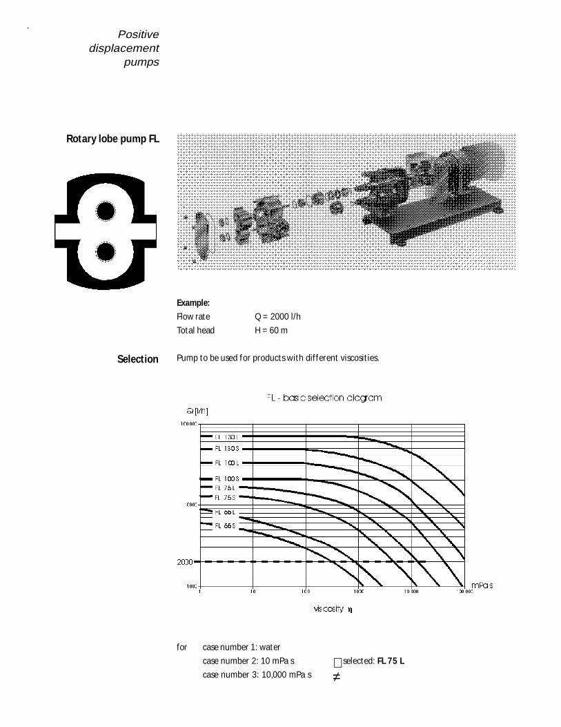
Example:
Flow rate Q = 2000 l/h
Total head H = 60 m
Pump to be used for products with dif ferent viscosit ies.
for case number 1: water
case number 2: 10 mPa s selected: FL 75 L
case number 3: 10,000 mPa s ≠
Rotary lobe pump FL
Selection
Positivedisplacementpumps
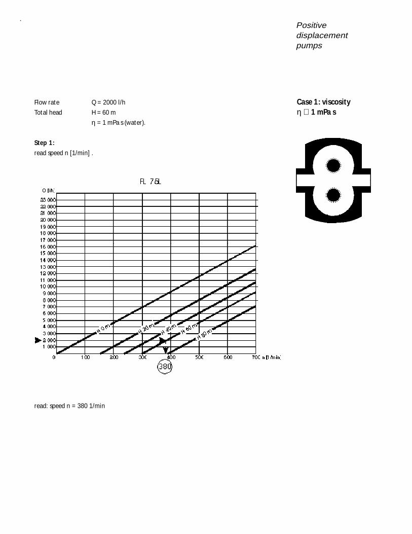
Flow rate Q = 2000 l/h
Total head H = 60 m
η = 1 mPa s (water).
Step 1:
read speed n [1/min] .
read: speed n = 380 1/min
Case 1: viscosityη ∪ 1 mPa s
Positivedisplacement
pumps
Step 2:
def ine viscosity factor
stated in the diagram: viscosity factor V = 1.8
Case 1: viscosityη ∪ 1 mPa s

Positivedisplacementpumps
Step 3:
Calculate the absorbed power N [kW] to select the pump drive.
N =(2 p + V) n C
1000× × ×
p = pressure in bar ∪ H/10
V = viscosity factor
n = speed with H = 0
C = f low rate/revolut ion [l/rev.]
Example:
Case 1: viscosityη ∪ 1 mPa s
Positivedisplacement
pumps
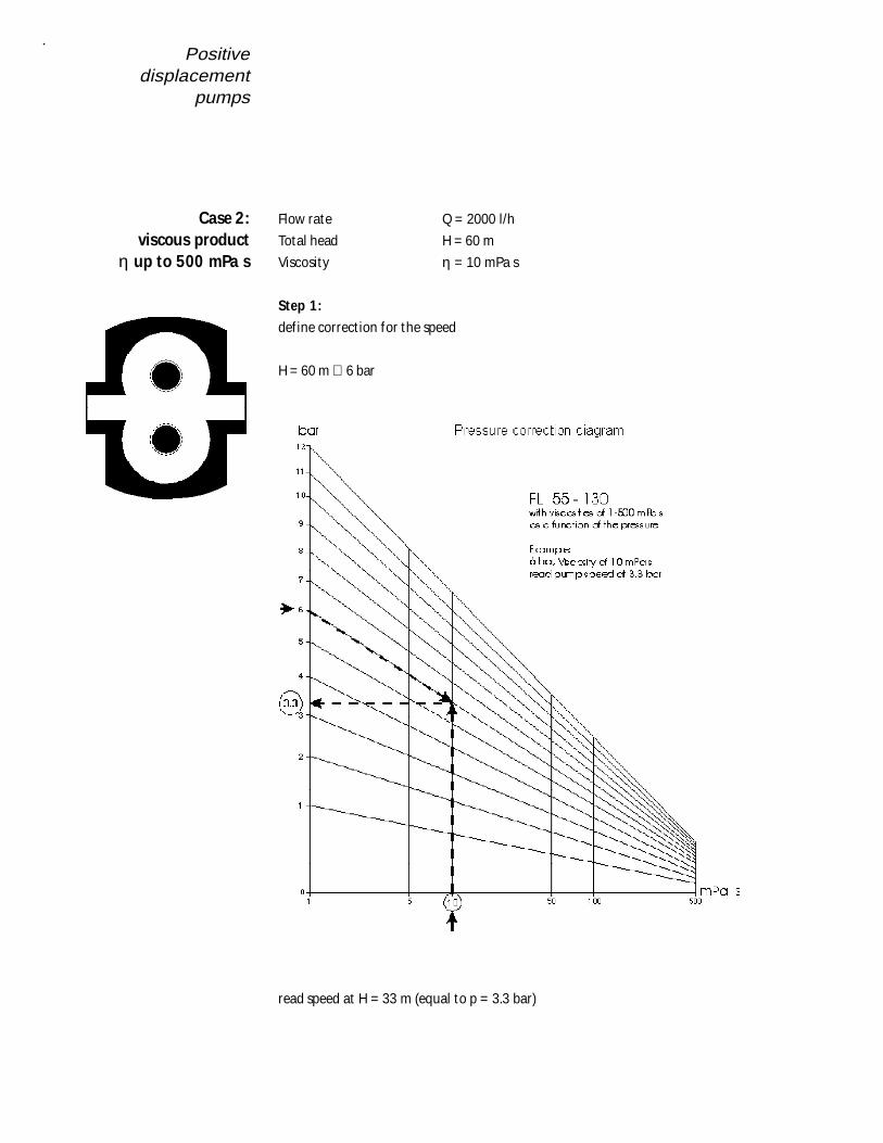
Flow rate Q = 2000 l/h
Total head H = 60 m
Viscosity η = 10 mPa s
Step 1:
def ine correct ion for the speed
H = 60 m ∪ 6 bar
read speed at H = 33 m (equal to p = 3.3 bar)
Case 2:viscous product
η up to 500 mPa s
Positivedisplacementpumps
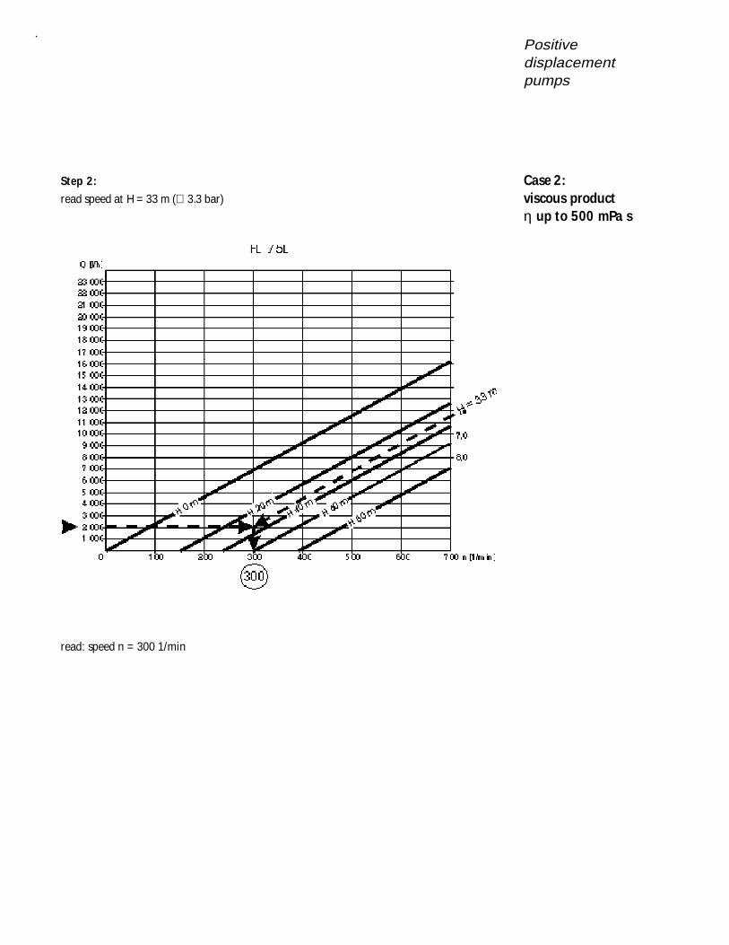
Step 2:
read speed at H = 33 m (∪ 3.3 bar)
read: speed n = 300 1/min
Case 2:viscous productη up to 500 mPa s
Positivedisplacement
pumps
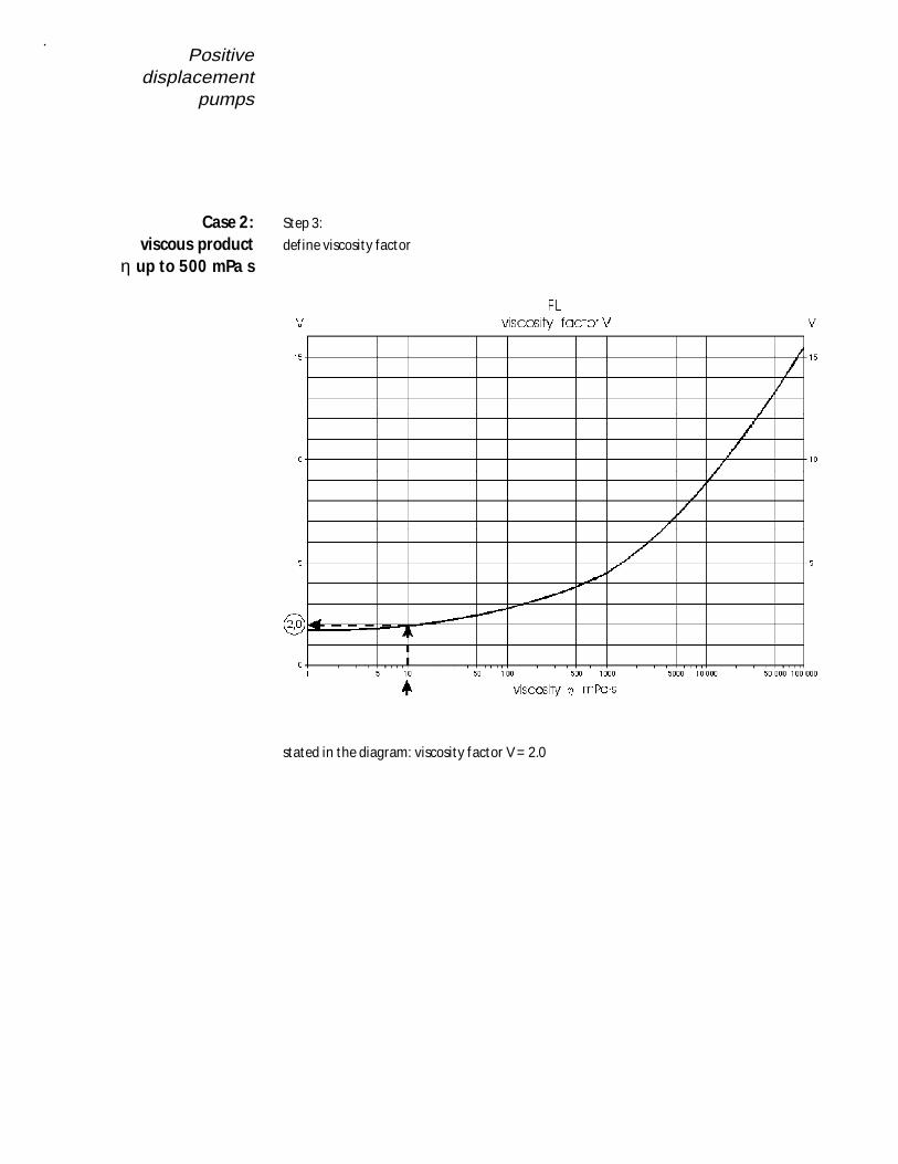
Step 3:
def ine viscosity factor
stated in the diagram: viscosity factor V = 2.0
Case 2:viscous product
η up to 500 mPa s
Positivedisplacementpumps
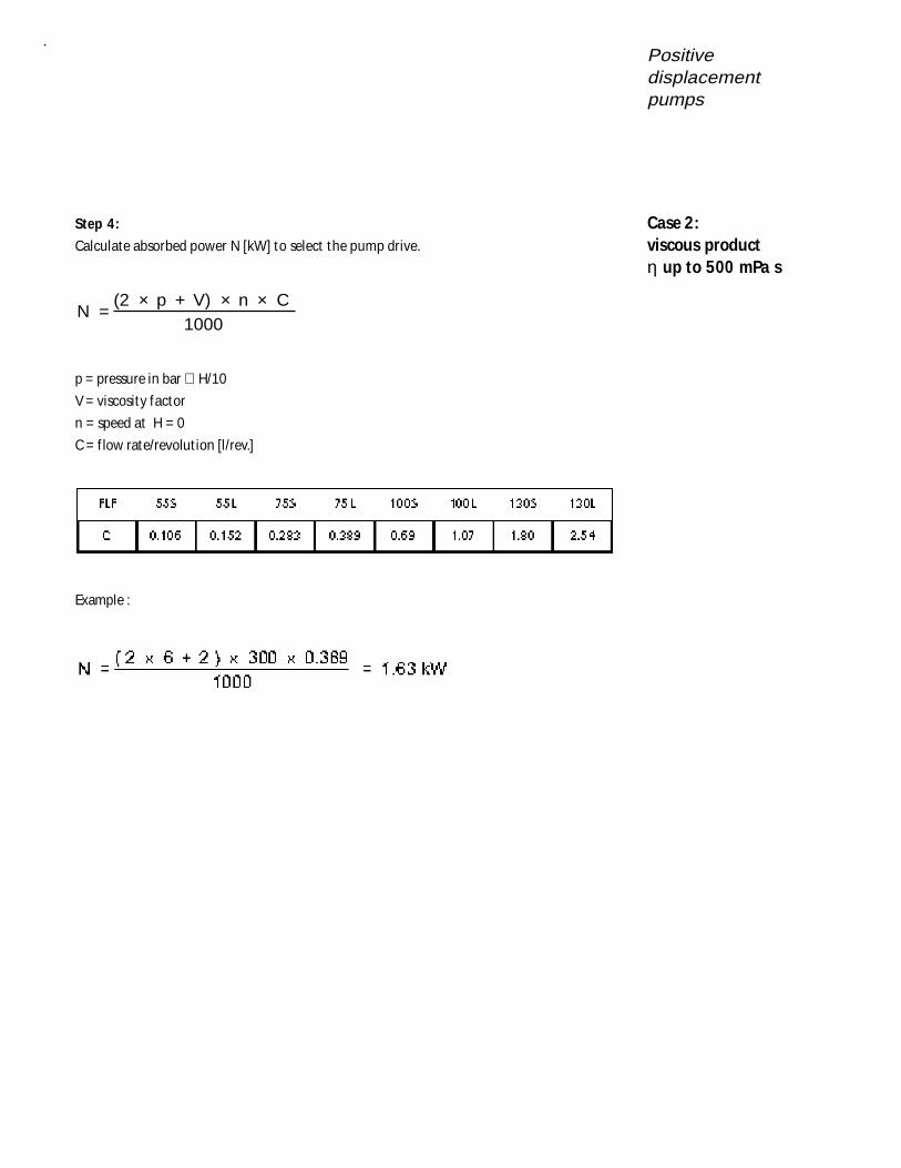
Step 4:
Calculate absorbed power N [kW] to select the pump drive.
N =(2 p + V) n C
1000× × ×
p = pressure in bar ∪ H/10
V = viscosity factor
n = speed at H = 0
C = f low rate/revolut ion [l/rev.]
Example :
Case 2:viscous productη up to 500 mPa s
Positivedisplacement
pumps
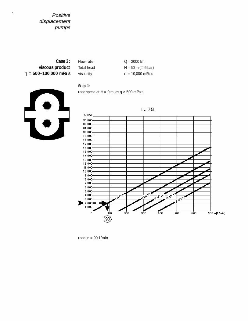
Flow rate Q = 2000 l/h
Total head H = 60 m (∪ 6 bar)
viscosity η = 10,000 mPa s
Step 1:
read speed at H = 0 m, as η > 500 mPa s
read: n = 90 1/min
Case 3:viscous product
η = 500–100,000 mPa s
Positivedisplacementpumps
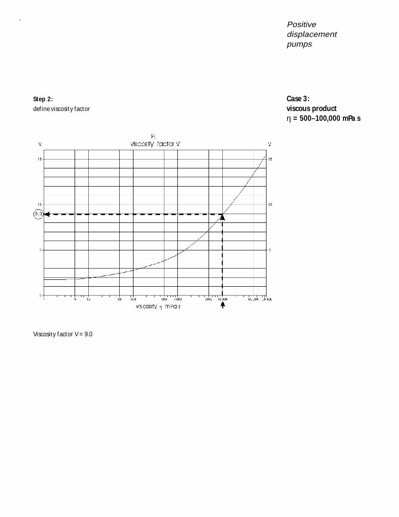
Step 2:
def ine viscosity factor
Viscosity factor V = 9.0
Case 3:viscous productη = 500–100,000 mPa s
Positivedisplacement
pumps
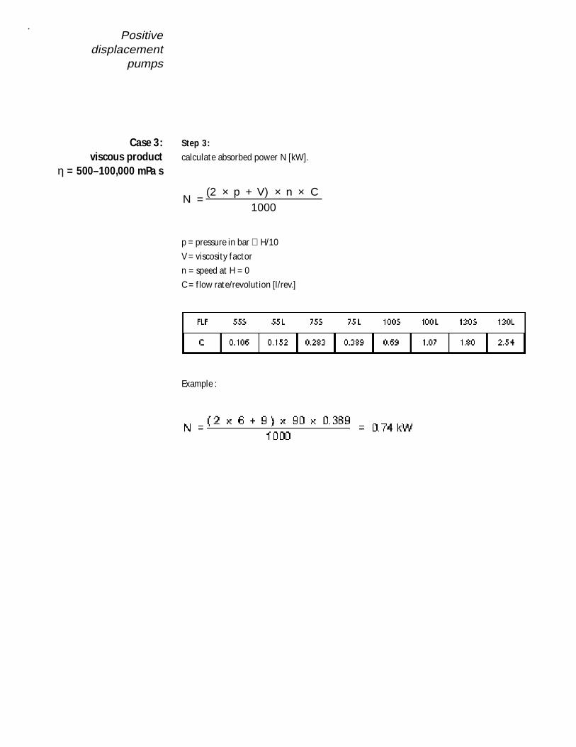
Step 3:
calculate absorbed power N [kW].
N =(2 p + V) n C
1000× × ×
p = pressure in bar ∪ H/10
V = viscosity factor
n = speed at H = 0
C = f low rate/revolut ion [l/rev.]
Example :
Case 3:viscous product
η = 500–100,000 mPa s
Mechanical sealselection
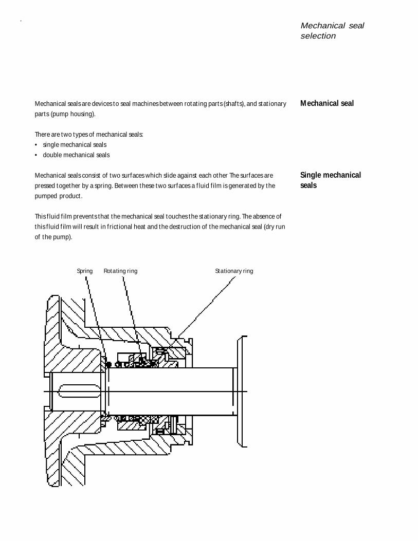
Mechanical seals are devices to seal machines between rotat ing parts (shaf ts), and stat ionary
parts (pump housing).
There are two types of mechanical seals:
• single mechanical seals
• double mechanical seals
Mechanical seals consist of two surfaces which slide against each other The surfaces are
pressed together by a spring. Between these two surfaces a f luid film is generated by the
pumped product .
This f luid f ilm prevents that the mechanical seal touches the stat ionary ring. The absence of
this f luid f ilm will result in f rict ional heat and the destruct ion of the mechanical seal (dry run
of the pump).
Mechanical seal
Single mechanicalseals
Spring Rotating ring Stationary ring

Mechanical sealselection
The spring is in the product . The product pressure acts addit ional to the spring on the
rotat ing seal part .
Therefore standard mechanical seals are used only for a pressure up to 10 bar. For higher
pressures, balanced mechanical seals are used.
In this case two mechanical seals are arranged in series. The inboard or, “primary seal” keeps
the product in the pump housing. The outboard or, “secondary seal” prevents leakage of the
f lush liquid into the atmoshere.
The double mechanical seals can be provided by Fristam in two dif ferent arrangements:
• Back to Back
• Face to Face
These mechanical seal arrangements are used,
• if a f luid product leakage needs to be avoided,
• when aggressive media are used or at high pressures and temperatures,
• for many polymerising, st icky media and media which tend to sedimentat ion,
• for vacuum applicat ions.
Double mechanicalseals
Mechanical sealselection
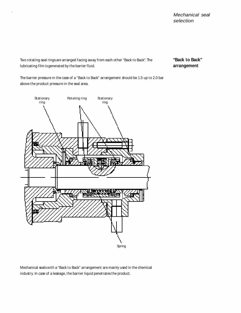
Two rotat ing seal rings are arranged facing away f rom each other “Back to Back”. The
lubricat ing f ilm is generated by the barrier f luid.
The barrier pressure in the case of a “Back to Back” arrangement should be 1.5 up to 2.0 bar
above the product pressure in the seal area.
Mechanical seals with a “Back to Back” arrangement are mainly used in the chemical
industry. In case of a leakage, the barrier liquid penetrates the product .
Stat ionary Rotating ring Stat ionary r ing ring
Spring
“Back to Back”arrangement
Mechanical sealselection
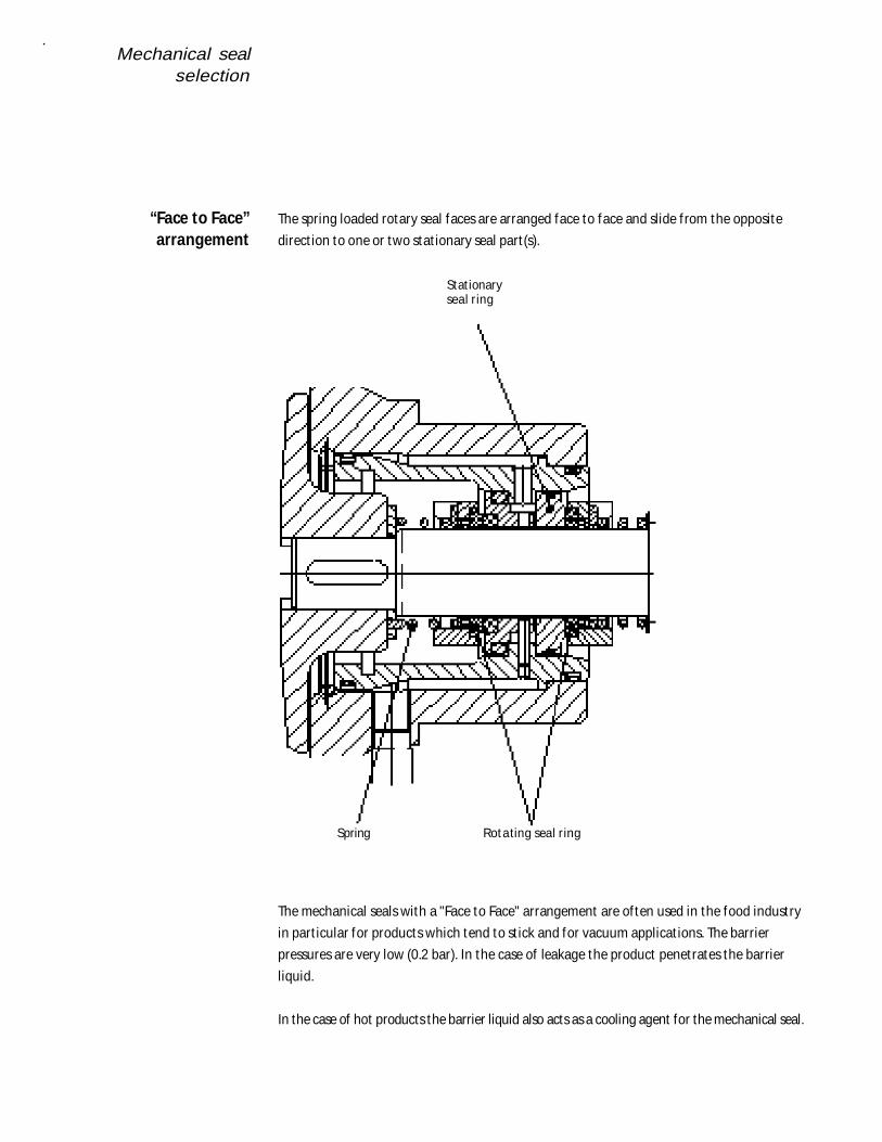
The spring loaded rotary seal faces are arranged face to face and slide f rom the opposite
direct ion to one or two stat ionary seal part (s).
The mechanical seals with a "Face to Face" arrangement are of ten used in the food industry
in part icular for products which tend to st ick and for vacuum applicat ions. The barrier
pressures are very low (0.2 bar). In the case of leakage the product penetrates the barrier
liquid.
In the case of hot products the barrier liquid also acts as a cooling agent for the mechanical seal.
“Face to Face”arrangement
Stat ionaryseal r ing
Spring Rotating seal r ing
Mechanical sealselection
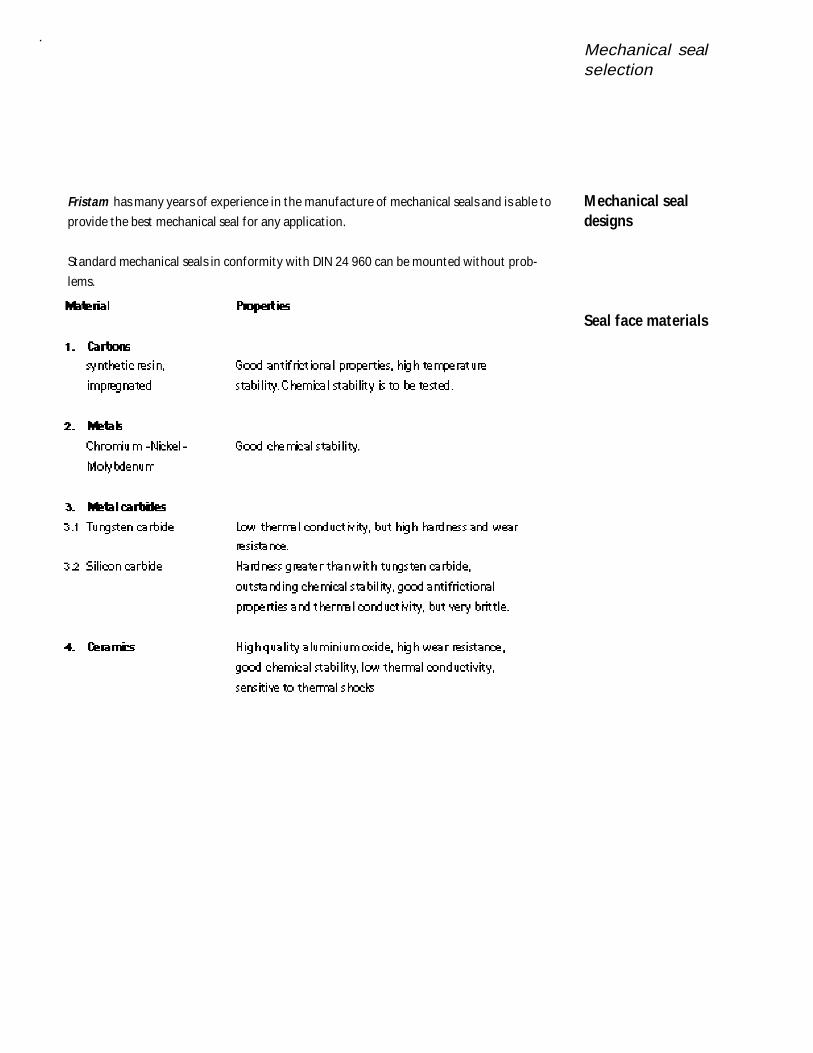
Fristam has many years of experience in the manufacture of mechanical seals and is able to
provide the best mechanical seal for any applicat ion.
Standard mechanical seals in conformity with DIN 24 960 can be mounted without prob-
lems.
Mechanical sealdesigns
Seal face materials
Mechanical sealselection
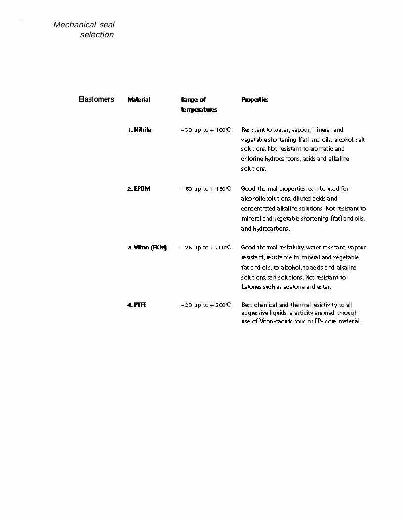
Elastomers
Pump cleaning
The t ransfer of hygienic, high quality products requires a clean pump. Therefore at the end
of a product ion process the pumps must be cleaned immediately. The plant needs to be
clean and f ree f rom germs before start ing a new product ion cycle.
Cleaning is the operat ion to remove all t races of product f rom the plant . A properly cleaned
surface is f ree f rom visible, percept ible or chemically detectable dirt deposits (residue).
The standard cleaning process for plants is the CIP - (Cleaning in Place). This implies clean-
ing without dismant ling of the plant by means of CIP f luids.
In the food industry a CIP process requires the following steps:
• preliminary rinsing with water
• f lushing with alkaline solut ion
• intermediate rinsing with water
• f lushing with acid
• rinsing with clean water
To clean the unit eff icient ly a turbulent f low of the CIP f luid is required. A minimum f low
velocity in pipes is usually 2 m/s.
Viscous f luids are of ten t ransferred by posit ive displacement pumps at low flow velocit ies. In
order to obtain the f low rate required for CIP it may be necessary to f it an addit ional clean-
ing pump such as a centrifugal pump.
Fristam pumps are fully CIP capable. They are characterised by:
• welded and ground joints
• round edges and angles
• smooth joining
• no narrow gaps and dead legs
• O- rings immersed in the pump housing
• smooth, nonporous internals with a high surface f inish
Cleaning
CIP
CIP plant cleaning
CIP compatible design
Pump cleaning
After CIP cleaning an addit ional sterilisat ion in place process (SIP) may be required when
highly sensit ive products are handled, inact ivat ing any micro-organisms which might be st ill
present in the pump.
The sterilisat ion can be carried out by means of chemicals, hot water or steam. In the dairy
industry the sterilisat ion temperature is approximately 145° C.
SIP
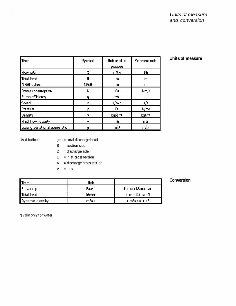
Units of measureand conversion
Used indices: geo = total discharge head
S = suct ion side
D = discharge side
E = inlet cross sect ion
A = discharge cross sect ion
V = loss
*) valid only for water
Units of measure
Conversion
Index
Cavitat ion . . . . . . . . . . . . . . . . . . . . . . . . . . . . . . . . . . . . . . . . . . . . . . . . . . . . . . . . . . . . . . . . . . . 24Centrifugal pumps connected in series . . . . . . . . . . . . . . . . . . . . . . . . . . . . . . . . . . . . . . . . . . . 24Centrifugal pumps, Features . . . . . . . . . . . . . . . . . . . . . . . . . . . . . . . . . . . . . . . . . . . . . . . . . . . . 20Centrifugal pumps parallely connected . . . . . . . . . . . . . . . . . . . . . . . . . . . . . . . . . . . . . . . . . . . 23Centrifugal pumps, pump ef f iciency . . . . . . . . . . . . . . . . . . . . . . . . . . . . . . . . . . . . . . . . . . . . . 30Centrifugal pumps, Q/H curve . . . . . . . . . . . . . . . . . . . . . . . . . . . . . . . . . . . . . . . . . . . . . . . . . . . 20Centrifugal pumps, select ion criteria . . . . . . . . . . . . . . . . . . . . . . . . . . . . . . . . . . . . . . . . . . . . . 27Centrifugal pumps, size select ion . . . . . . . . . . . . . . . . . . . . . . . . . . . . . . . . . . . . . . . . . . . . . 28, 32Centrifugal pump types . . . . . . . . . . . . . . . . . . . . . . . . . . . . . . . . . . . . . . . . . . . . . . . . . . . . . . . . 26Conversion . . . . . . . . . . . . . . . . . . . . . . . . . . . . . . . . . . . . . . . . . . . . . . . . . . . . . . . . . . . . . . . . . . 69Correct ion of the impeller diameter . . . . . . . . . . . . . . . . . . . . . . . . . . . . . . . . . . . . . . . . . . . . . . 22Double mechanical seals . . . . . . . . . . . . . . . . . . . . . . . . . . . . . . . . . . . . . . . . . . . . . . . . . . . . . . . 62Flow behavior of f luids . . . . . . . . . . . . . . . . . . . . . . . . . . . . . . . . . . . . . . . . . . . . . . . . . . . . . . . . 10Flow rate . . . . . . . . . . . . . . . . . . . . . . . . . . . . . . . . . . . . . . . . . . . . . . . . . . . . . . . . . . . . . . . . . . . . . 8Laminar f low . . . . . . . . . . . . . . . . . . . . . . . . . . . . . . . . . . . . . . . . . . . . . . . . . . . . . . . . . . . . . . . . 12Loss of head caused by f itt ings . . . . . . . . . . . . . . . . . . . . . . . . . . . . . . . . . . . . . . . . . . . . . . . . . . 17Loss of head in st raight pipe runs . . . . . . . . . . . . . . . . . . . . . . . . . . . . . . . . . . . . . . . . . . . . . . . . 16NPSH value . . . . . . . . . . . . . . . . . . . . . . . . . . . . . . . . . . . . . . . . . . . . . . . . . . . . . . . . . . . . . . . . . . 14NPSH value of the plant . . . . . . . . . . . . . . . . . . . . . . . . . . . . . . . . . . . . . . . . . . . . . . . . . . . . . . . 14NPSH value of the pump . . . . . . . . . . . . . . . . . . . . . . . . . . . . . . . . . . . . . . . . . . . . . . . . . . . . . . . 14Orif ice plate calculation . . . . . . . . . . . . . . . . . . . . . . . . . . . . . . . . . . . . . . . . . . . . . . . . . . . . . . . 21Posit ive displacement pump, features . . . . . . . . . . . . . . . . . . . . . . . . . . . . . . . . . . . . . . . . . . . . 35Posit ive displacement pump, operating scheme . . . . . . . . . . . . . . . . . . . . . . . . . . . . . . . . . . . .35Power consumpt ion of the pump . . . . . . . . . . . . . . . . . . . . . . . . 8, 30, 33, 42, 46, 49, 53, 57, 60Pump ef f iciency . . . . . . . . . . . . . . . . . . . . . . . . . . . . . . . . . . . . . . . . . . . . . . . . . . . . . . . . . . . . . . 30Pump speed control . . . . . . . . . . . . . . . . . . . . . . . . . . . . . . . . . . . . . . . . . . . . . . . . . . . . . . . . 23, 36Pump type selection . . . . . . . . . . . . . . . . . . . . . . . . . . . . . . . . . . . . . . . . . . . . . . . . . . . . . . . . . . 19Q/H curve of centrifugal pumps . . . . . . . . . . . . . . . . . . . . . . . . . . . . . . . . . . . . . . . . . . . . . . . . . 20Reynolds number . . . . . . . . . . . . . . . . . . . . . . . . . . . . . . . . . . . . . . . . . . . . . . . . . . . . . . . . . . . . . 13Single mechanical seals . . . . . . . . . . . . . . . . . . . . . . . . . . . . . . . . . . . . . . . . . . . . . . . . . . . . . . . . 61Throt t ling the f low . . . . . . . . . . . . . . . . . . . . . . . . . . . . . . . . . . . . . . . . . . . . . . . . . . . . . . . . . . . . 21Total head . . . . . . . . . . . . . . . . . . . . . . . . . . . . . . . . . . . . . . . . . . . . . . . . . . . . . . . . . . . . . . . . . . . . 8Turbulent flow . . . . . . . . . . . . . . . . . . . . . . . . . . . . . . . . . . . . . . . . . . . . . . . . . . . . . . . . . . . . . . . 12Types of f low . . . . . . . . . . . . . . . . . . . . . . . . . . . . . . . . . . . . . . . . . . . . . . . . . . . . . . . . . . . . . . . . 12Units of measure . . . . . . . . . . . . . . . . . . . . . . . . . . . . . . . . . . . . . . . . . . . . . . . . . . . . . . . . . . . . . 69Vapour pressure . . . . . . . . . . . . . . . . . . . . . . . . . . . . . . . . . . . . . . . . . . . . . . . . . . . . . . . . . . . . . . 25Viscosity . . . . . . . . . . . . . . . . . . . . . . . . . . . . . . . . . . . . . . . . . . . . . . . . . . . . . . . . . . . . . . . . . . 9, 36