Embed Size (px)
Citation preview
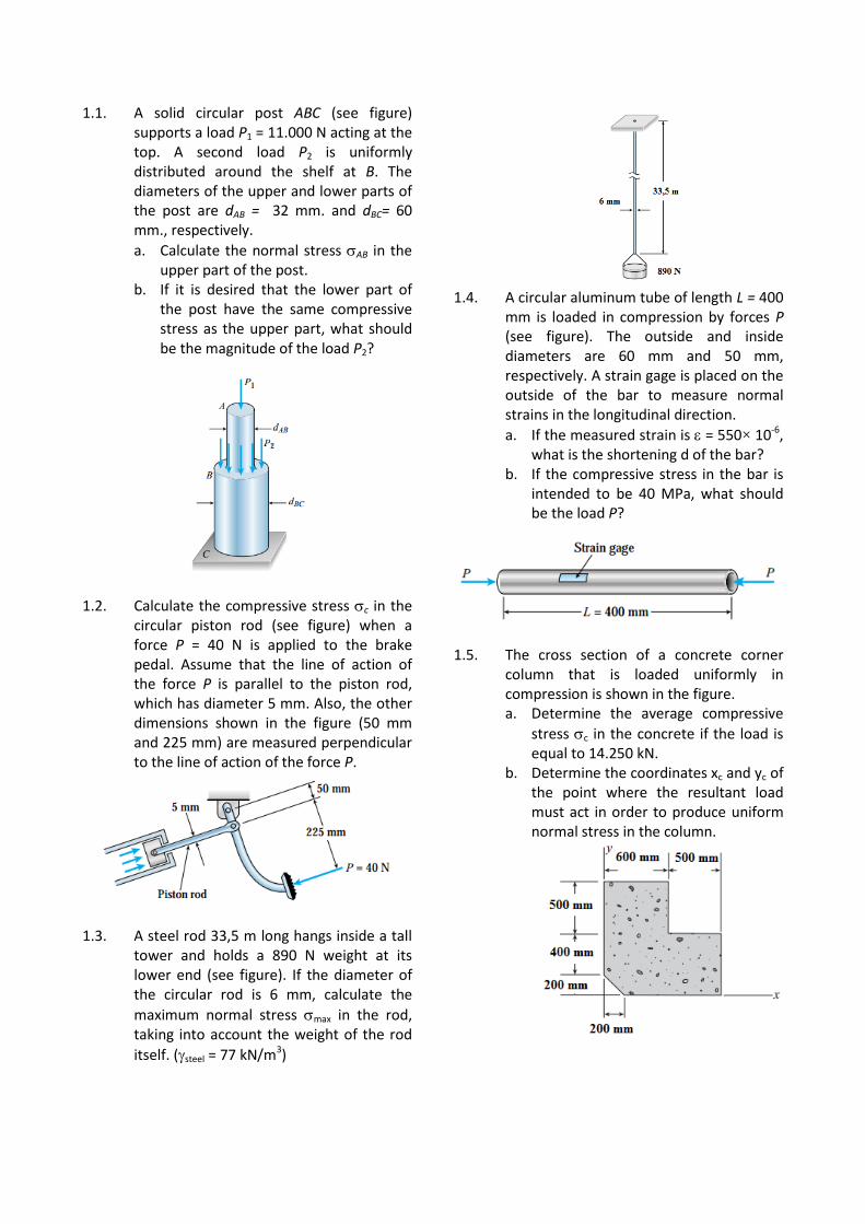
1.1. A solid circular post ABC (see figure) supports a load P1 = 11.000 N acting at the top. A second load P2 is uniformly distributed around the shelf at B. The diameters of the upper and lower parts of the post are dAB = 32 mm. and dBC= 60 mm., respectively.
a. Calculate the normal stress AB in the upper part of the post.
b. If it is desired that the lower part of the post have the same compressive stress as the upper part, what should be the magnitude of the load P2?
1.2. Calculate the compressive stress c in the circular piston rod (see figure) when a force P = 40 N is applied to the brake pedal. Assume that the line of action of the force P is parallel to the piston rod, which has diameter 5 mm. Also, the other dimensions shown in the figure (50 mm and 225 mm) are measured perpendicular to the line of action of the force P.
1.3. A steel rod 33,5 m long hangs inside a tall tower and holds a 890 N weight at its lower end (see figure). If the diameter of the circular rod is 6 mm, calculate the
maximum normal stress max in the rod, taking into account the weight of the rod
itself. (steel = 77 kN/m3)
1.4. A circular aluminum tube of length L = 400
mm is loaded in compression by forces P (see figure). The outside and inside diameters are 60 mm and 50 mm, respectively. A strain gage is placed on the outside of the bar to measure normal strains in the longitudinal direction.
a. If the measured strain is = 550× 10-6, what is the shortening d of the bar?
b. If the compressive stress in the bar is intended to be 40 MPa, what should be the load P?
1.5. The cross section of a concrete corner
column that is loaded uniformly in compression is shown in the figure. a. Determine the average compressive
stress c in the concrete if the load is equal to 14.250 kN.
b. Determine the coordinates xc and yc of the point where the resultant load must act in order to produce uniform normal stress in the column.
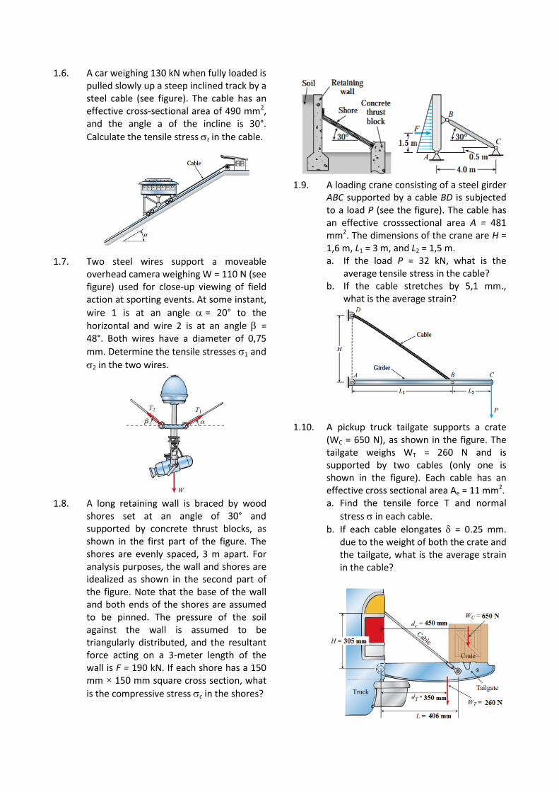
1.6. A car weighing 130 kN when fully loaded is pulled slowly up a steep inclined track by a steel cable (see figure). The cable has an effective cross-sectional area of 490 mm2, and the angle a of the incline is 30°.
Calculate the tensile stress t in the cable.
1.7. Two steel wires support a moveable overhead camera weighing W = 110 N (see figure) used for close-up viewing of field action at sporting events. At some instant,
wire 1 is at an angle = 20° to the
horizontal and wire 2 is at an angle = 48°. Both wires have a diameter of 0,75
mm. Determine the tensile stresses 1 and
2 in the two wires.
1.8. A long retaining wall is braced by wood
shores set at an angle of 30° and supported by concrete thrust blocks, as shown in the first part of the figure. The shores are evenly spaced, 3 m apart. For analysis purposes, the wall and shores are idealized as shown in the second part of the figure. Note that the base of the wall and both ends of the shores are assumed to be pinned. The pressure of the soil against the wall is assumed to be triangularly distributed, and the resultant force acting on a 3-meter length of the wall is F = 190 kN. If each shore has a 150 mm × 150 mm square cross section, what
is the compressive stress c in the shores?
1.9. A loading crane consisting of a steel girder
ABC supported by a cable BD is subjected to a load P (see the figure). The cable has an effective crosssectional area A = 481 mm2. The dimensions of the crane are H = 1,6 m, L1 = 3 m, and L2 = 1,5 m. a. If the load P = 32 kN, what is the
average tensile stress in the cable? b. If the cable stretches by 5,1 mm.,
what is the average strain?
1.10. A pickup truck tailgate supports a crate
(WC = 650 N), as shown in the figure. The tailgate weighs WT = 260 N and is supported by two cables (only one is shown in the figure). Each cable has an effective cross sectional area Ae = 11 mm2. a. Find the tensile force T and normal
stress in each cable.
b. If each cable elongates = 0.25 mm. due to the weight of both the crate and the tailgate, what is the average strain in the cable?
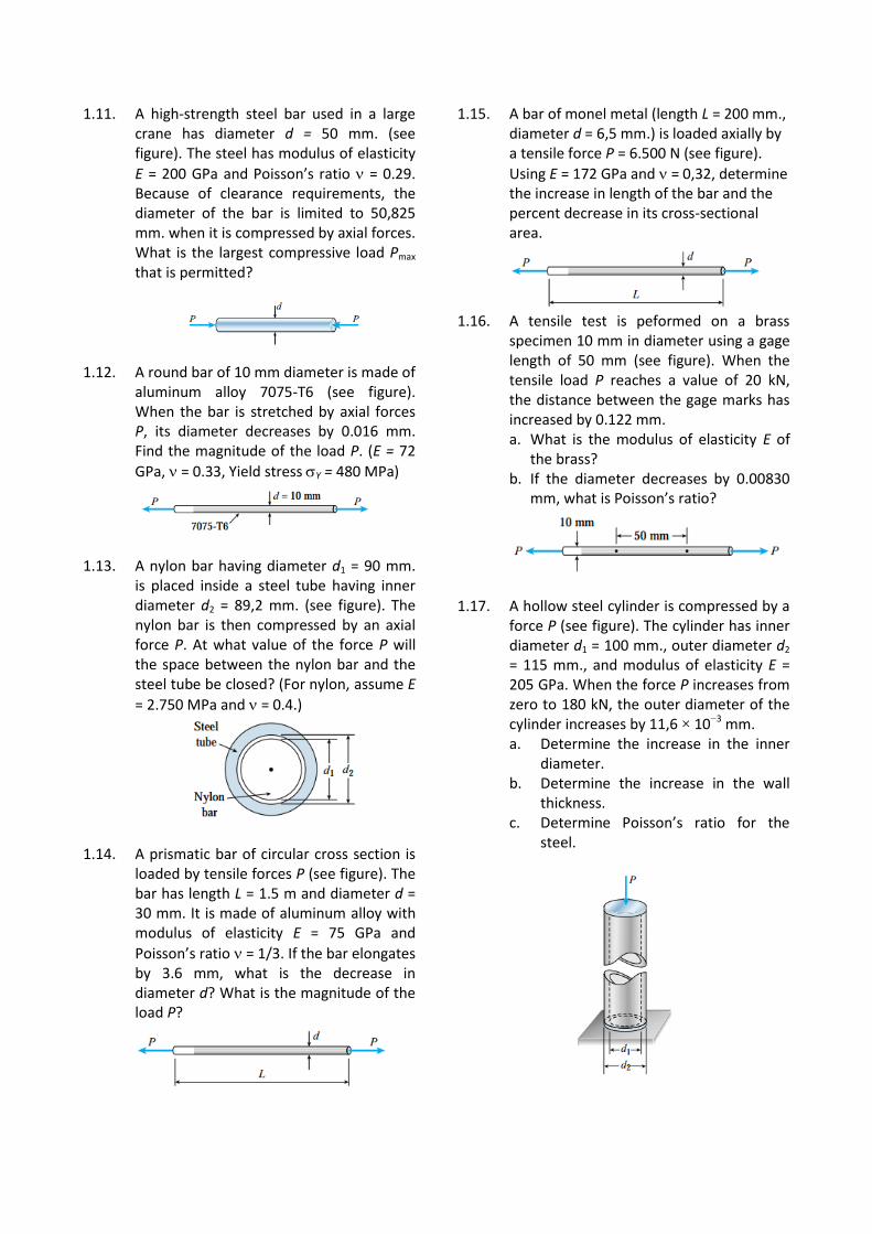
1.11. A high-strength steel bar used in a large crane has diameter d = 50 mm. (see figure). The steel has modulus of elasticity
E = 200 GPa and Poisson’s ratio = 0.29. Because of clearance requirements, the diameter of the bar is limited to 50,825 mm. when it is compressed by axial forces. What is the largest compressive load Pmax that is permitted?
1.12. A round bar of 10 mm diameter is made of aluminum alloy 7075-T6 (see figure). When the bar is stretched by axial forces P, its diameter decreases by 0.016 mm. Find the magnitude of the load P. (E = 72
GPa, = 0.33, Yield stress Y = 480 MPa)
1.13. A nylon bar having diameter d1 = 90 mm. is placed inside a steel tube having inner diameter d2 = 89,2 mm. (see figure). The nylon bar is then compressed by an axial force P. At what value of the force P will the space between the nylon bar and the steel tube be closed? (For nylon, assume E
= 2.750 MPa and = 0.4.)
1.14. A prismatic bar of circular cross section is loaded by tensile forces P (see figure). The bar has length L = 1.5 m and diameter d = 30 mm. It is made of aluminum alloy with modulus of elasticity E = 75 GPa and
Poisson’s ratio = 1/3. If the bar elongates by 3.6 mm, what is the decrease in diameter d? What is the magnitude of the load P?
1.15. A bar of monel metal (length L = 200 mm., diameter d = 6,5 mm.) is loaded axially by a tensile force P = 6.500 N (see figure).
Using E = 172 GPa and = 0,32, determine the increase in length of the bar and the percent decrease in its cross-sectional area.
1.16. A tensile test is peformed on a brass
specimen 10 mm in diameter using a gage length of 50 mm (see figure). When the tensile load P reaches a value of 20 kN, the distance between the gage marks has increased by 0.122 mm. a. What is the modulus of elasticity E of
the brass? b. If the diameter decreases by 0.00830
mm, what is Poisson’s ratio?
1.17. A hollow steel cylinder is compressed by a force P (see figure). The cylinder has inner diameter d1 = 100 mm., outer diameter d2 = 115 mm., and modulus of elasticity E = 205 GPa. When the force P increases from zero to 180 kN, the outer diameter of the cylinder increases by 11,6 × 10⁻³ mm. a. Determine the increase in the inner
diameter. b. Determine the increase in the wall
thickness. c. Determine Poisson’s ratio for the
steel.
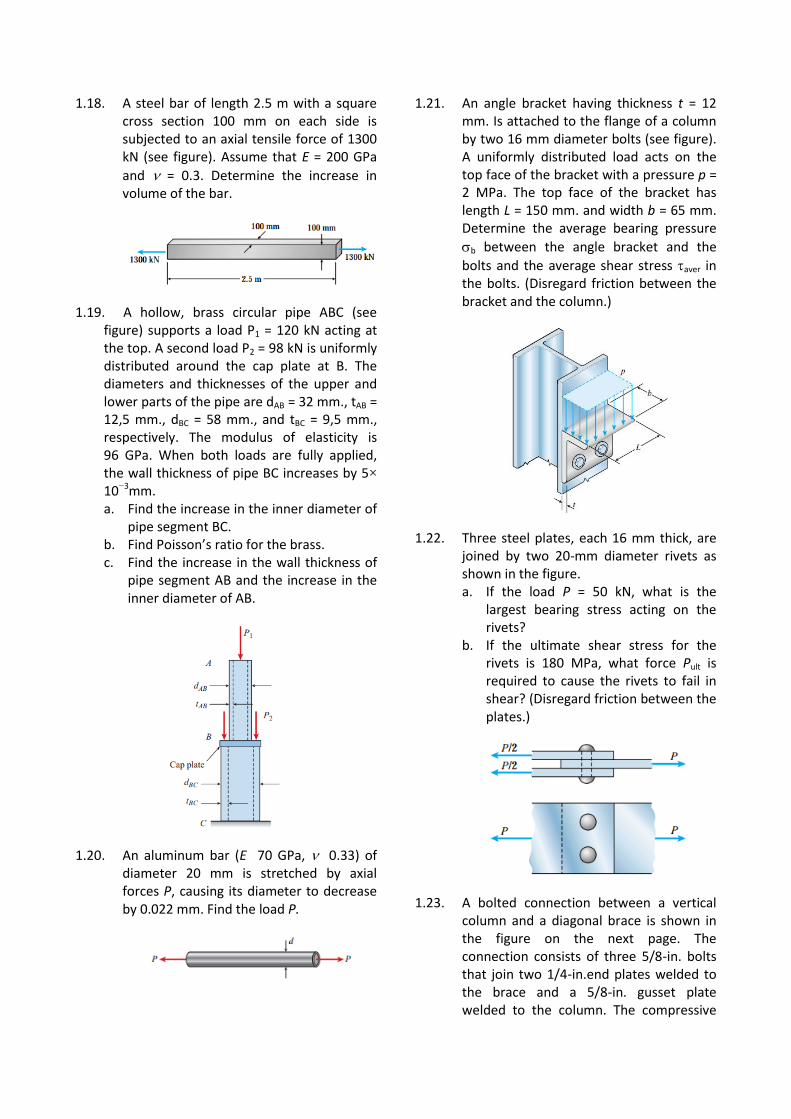
1.18. A steel bar of length 2.5 m with a square cross section 100 mm on each side is subjected to an axial tensile force of 1300 kN (see figure). Assume that E = 200 GPa
and = 0.3. Determine the increase in volume of the bar.
1.19. A hollow, brass circular pipe ABC (see figure) supports a load P1 = 120 kN acting at the top. A second load P2 = 98 kN is uniformly distributed around the cap plate at B. The diameters and thicknesses of the upper and lower parts of the pipe are dAB = 32 mm., tAB = 12,5 mm., dBC = 58 mm., and tBC = 9,5 mm., respectively. The modulus of elasticity is 96 GPa. When both loads are fully applied, the wall thickness of pipe BC increases by 5× 10⁻³mm. a. Find the increase in the inner diameter of
pipe segment BC. b. Find Poisson’s ratio for the brass. c. Find the increase in the wall thickness of
pipe segment AB and the increase in the inner diameter of AB.
1.20. An aluminum bar (E 70 GPa, 0.33) of diameter 20 mm is stretched by axial forces P, causing its diameter to decrease by 0.022 mm. Find the load P.
1.21. An angle bracket having thickness t = 12 mm. Is attached to the flange of a column by two 16 mm diameter bolts (see figure). A uniformly distributed load acts on the top face of the bracket with a pressure p = 2 MPa. The top face of the bracket has length L = 150 mm. and width b = 65 mm. Determine the average bearing pressure
b between the angle bracket and the
bolts and the average shear stress aver in the bolts. (Disregard friction between the bracket and the column.)
1.22. Three steel plates, each 16 mm thick, are joined by two 20-mm diameter rivets as shown in the figure. a. If the load P = 50 kN, what is the
largest bearing stress acting on the rivets?
b. If the ultimate shear stress for the rivets is 180 MPa, what force Pult is required to cause the rivets to fail in shear? (Disregard friction between the plates.)
1.23. A bolted connection between a vertical column and a diagonal brace is shown in the figure on the next page. The connection consists of three 5/8-in. bolts that join two 1/4-in.end plates welded to the brace and a 5/8-in. gusset plate welded to the column. The compressive
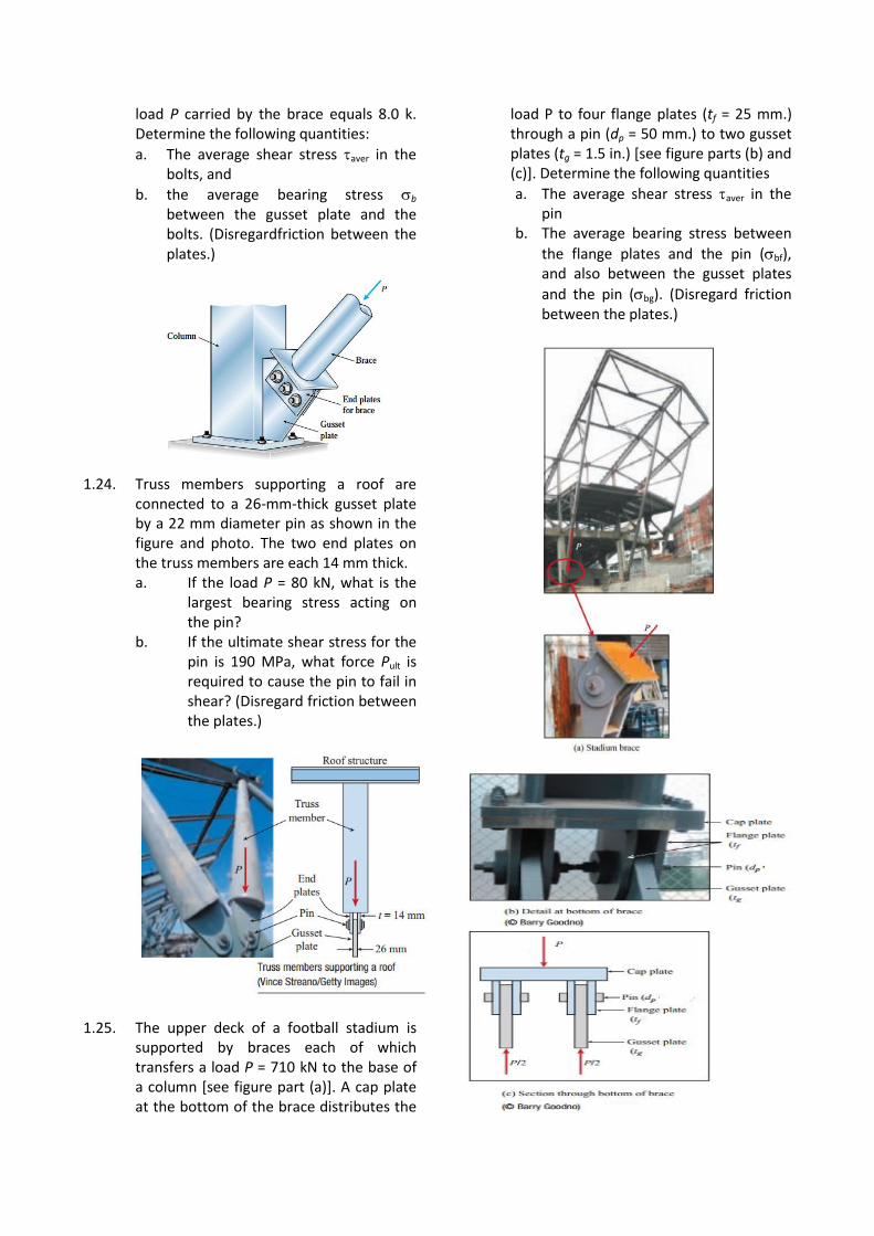
load P carried by the brace equals 8.0 k. Determine the following quantities:
a. The average shear stress aver in the bolts, and
b. the average bearing stress b between the gusset plate and the bolts. (Disregardfriction between the plates.)
1.24. Truss members supporting a roof are connected to a 26-mm-thick gusset plate by a 22 mm diameter pin as shown in the figure and photo. The two end plates on the truss members are each 14 mm thick. a. If the load P = 80 kN, what is the
largest bearing stress acting on the pin?
b. If the ultimate shear stress for the pin is 190 MPa, what force Pult is required to cause the pin to fail in shear? (Disregard friction between the plates.)
1.25. The upper deck of a football stadium is supported by braces each of which transfers a load P = 710 kN to the base of a column [see figure part (a)]. A cap plate at the bottom of the brace distributes the
load P to four flange plates (tf = 25 mm.) through a pin (dp = 50 mm.) to two gusset plates (tg = 1.5 in.) [see figure parts (b) and (c)]. Determine the following quantities
a. The average shear stress aver in the pin
b. The average bearing stress between
the flange plates and the pin (bf), and also between the gusset plates
and the pin (bg). (Disregard friction between the plates.)
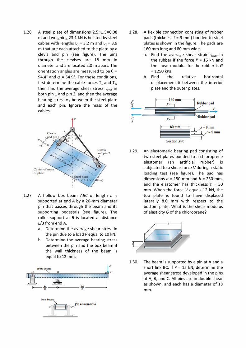
1.26. A steel plate of dimensions 2.5×1.5×0.08 m and weighing 23.1 kN is hoisted by steel cables with lengths L1 = 3.2 m and L2 = 3.9 m that are each attached to the plate by a clevis and pin (see figure). The pins through the clevises are 18 mm in diameter and are located 2.0 m apart. The
orientation angles are measured to be =
94.4° and = 54.9°. For these conditions, first determine the cable forces T1 and T2,
then find the average shear stress aver in both pin 1 and pin 2, and then the average
bearing stress b between the steel plate and each pin. Ignore the mass of the cables.
1.27. A hollow box beam ABC of length L is supported at end A by a 20-mm diameter pin that passes through the beam and its supporting pedestals (see figure). The roller support at B is located at distance L/3 from end A. a. Determine the average shear stress in
the pin due to a load P equal to 10 kN. b. Determine the average bearing stress
between the pin and the box beam if the wall thickness of the beam is equal to 12 mm.
1.28. A flexible connection consisting of rubber pads (thickness t = 9 mm) bonded to steel plates is shown in the figure. The pads are 160 mm long and 80 mm wide.
a. Find the average shear strain aver in the rubber if the force P = 16 kN and the shear modulus for the rubber is G = 1250 kPa.
b. Find the relative horizontal
displacement between the interior plate and the outer plates.
1.29. An elastomeric bearing pad consisting of two steel plates bonded to a chloroprene elastomer (an artificial rubber) is subjected to a shear force V during a static loading test (see figure). The pad has dimensions a = 150 mm and b = 250 mm, and the elastomer has thickness t = 50 mm. When the force V equals 12 kN, the top plate is found to have displaced laterally 8.0 mm with respect to the bottom plate. What is the shear modulus of elasticity G of the chloroprene?
1.30. The beam is supported by a pin at A and a short link BC. If P = 15 kN, determine the average shear stress developed in the pins at A, B, and C. All pins are in double shear as shown, and each has a diameter of 18 mm.
1.31. A bar of solid circular cross section is loaded in tension by forces P (see figure). The bar has length L = 380 mm and diameter d = 6 mm. The material is a magnesium alloy having modulus of elasticity E = 42.7 GPa. The allowable stress in tension is sallow 89.6 GPa and the elongation of the bar must not exceed 0.08 mm.
1.32. A tie-down on the deck of a sailboat consists of a bent bar bolted at both ends, as shown in the figure. The diameter dB of the bar is 6 mm, the diameter dW of the washers is 22 mm, and the thickness t of the fiberglass deck is 10 mm. If the allowable shear stress in the fiberglass is 2.1 MPa, and the allowable bearing pressure between the washer and the fiberglass is 3.8 MPa, what is the allowable load Pallow on the tie-down?
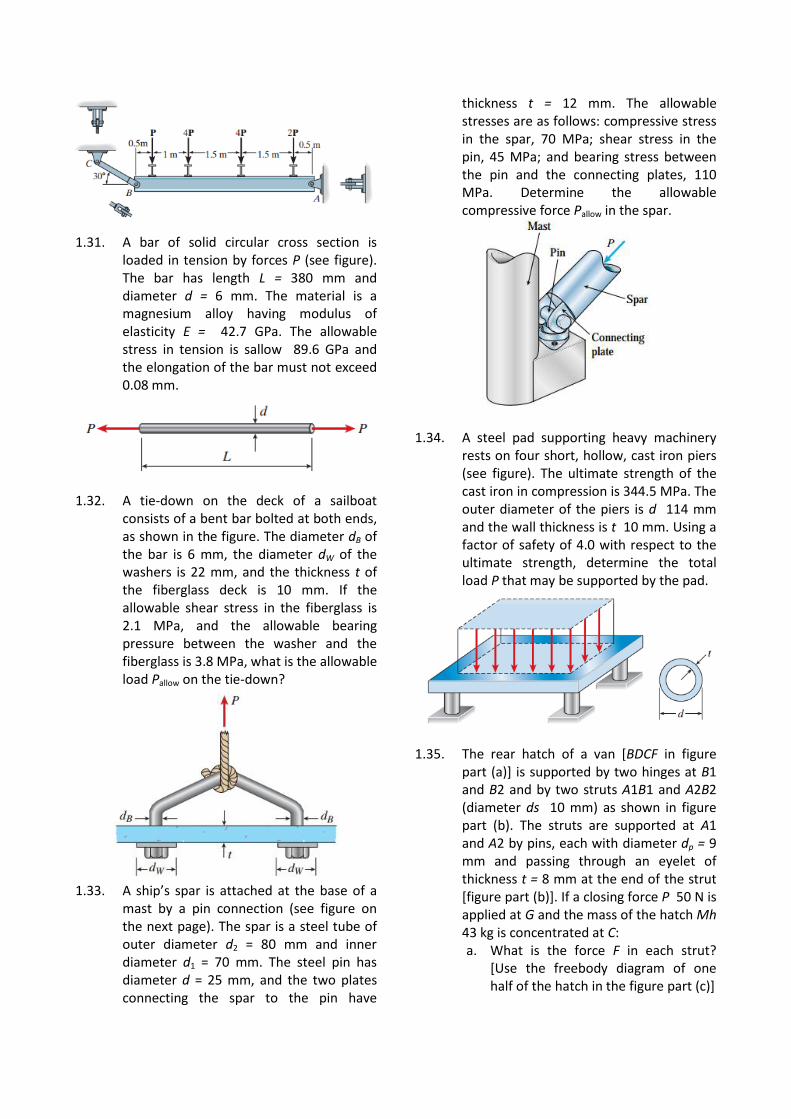
1.33. A ship’s spar is attached at the base of a
mast by a pin connection (see figure on the next page). The spar is a steel tube of outer diameter d2 = 80 mm and inner diameter d1 = 70 mm. The steel pin has diameter d = 25 mm, and the two plates connecting the spar to the pin have
thickness t = 12 mm. The allowable stresses are as follows: compressive stress in the spar, 70 MPa; shear stress in the pin, 45 MPa; and bearing stress between the pin and the connecting plates, 110 MPa. Determine the allowable compressive force Pallow in the spar.
1.34. A steel pad supporting heavy machinery
rests on four short, hollow, cast iron piers (see figure). The ultimate strength of the cast iron in compression is 344.5 MPa. The outer diameter of the piers is d 114 mm and the wall thickness is t 10 mm. Using a factor of safety of 4.0 with respect to the ultimate strength, determine the total load P that may be supported by the pad.
1.35. The rear hatch of a van [BDCF in figure part (a)] is supported by two hinges at B1 and B2 and by two struts A1B1 and A2B2 (diameter ds 10 mm) as shown in figure part (b). The struts are supported at A1 and A2 by pins, each with diameter dp = 9 mm and passing through an eyelet of thickness t = 8 mm at the end of the strut [figure part (b)]. If a closing force P 50 N is applied at G and the mass of the hatch Mh 43 kg is concentrated at C: a. What is the force F in each strut?
[Use the freebody diagram of one half of the hatch in the figure part (c)]
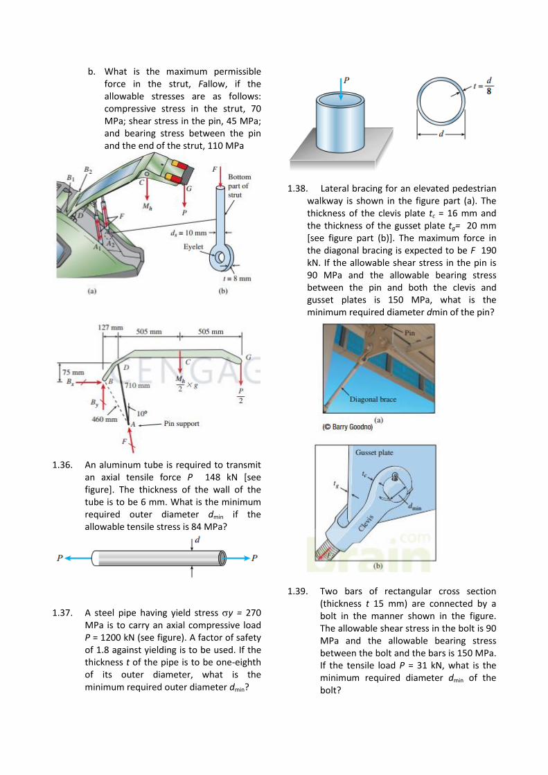
b. What is the maximum permissible force in the strut, Fallow, if the allowable stresses are as follows: compressive stress in the strut, 70 MPa; shear stress in the pin, 45 MPa; and bearing stress between the pin and the end of the strut, 110 MPa
1.36. An aluminum tube is required to transmit
an axial tensile force P 148 kN [see figure]. The thickness of the wall of the tube is to be 6 mm. What is the minimum required outer diameter dmin if the allowable tensile stress is 84 MPa?
1.37. A steel pipe having yield stress y = 270 MPa is to carry an axial compressive load P = 1200 kN (see figure). A factor of safety of 1.8 against yielding is to be used. If the thickness t of the pipe is to be one-eighth of its outer diameter, what is the minimum required outer diameter dmin?
1.38. Lateral bracing for an elevated pedestrian walkway is shown in the figure part (a). The thickness of the clevis plate tc = 16 mm and the thickness of the gusset plate tg= 20 mm [see figure part (b)]. The maximum force in the diagonal bracing is expected to be F 190 kN. If the allowable shear stress in the pin is 90 MPa and the allowable bearing stress between the pin and both the clevis and gusset plates is 150 MPa, what is the minimum required diameter dmin of the pin?
1.39. Two bars of rectangular cross section (thickness t 15 mm) are connected by a bolt in the manner shown in the figure. The allowable shear stress in the bolt is 90 MPa and the allowable bearing stress between the bolt and the bars is 150 MPa. If the tensile load P = 31 kN, what is the minimum required diameter dmin of the bolt?
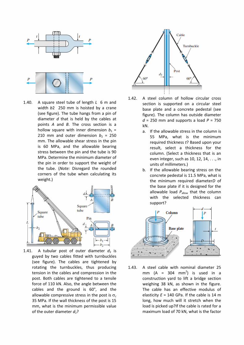
1.40. A square steel tube of length L 6 m and width b2 250 mm is hoisted by a crane (see figure). The tube hangs from a pin of diameter d that is held by the cables at points A and B. The cross section is a hollow square with inner dimension b1 = 210 mm and outer dimension b2 = 250 mm. The allowable shear stress in the pin is 60 MPa, and the allowable bearing stress between the pin and the tube is 90 MPa. Determine the minimum diameter of the pin in order to support the weight of the tube. (Note: Disregard the rounded corners of the tube when calculating its weight.)
1.41. A tubular post of outer diameter d2 is
guyed by two cables fitted with turnbuckles (see figure). The cables are tightened by rotating the turnbuckles, thus producing tension in the cables and compression in the post. Both cables are tightened to a tensile force of 110 kN. Also, the angle between the cables and the ground is 60°, and the
allowable compressive stress in the post is c 35 MPa. If the wall thickness of the post is 15 mm, what is the minimum permissible value of the outer diameter d2?
1.42. A steel column of hollow circular cross
section is supported on a circular steel base plate and a concrete pedestal (see figure). The column has outside diameter d = 250 mm and supports a load P = 750 kN. a. If the allowable stress in the column is
55 MPa, what is the minimum required thickness t? Based upon your result, select a thickness for the column. (Select a thickness that is an even integer, such as 10, 12, 14, . . ., in units of millimeters.)
b. If the allowable bearing stress on the concrete pedestal is 11.5 MPa, what is the minimum required diameterD of the base plate if it is designed for the allowable load Pallow that the column with the selected thickness can support?
1.43. A steel cable with nominal diameter 25 mm (A = 304 mm2) is used in a construction yard to lift a bridge section weighing 38 kN, as shown in the figure. The cable has an effective modulus of elasticity E = 140 GPa. If the cable is 14 m long, how much will it stretch when the load is picked up?If the cable is rated for a maximum load of 70 kN, what is the factor
of safety with respect to failure of the cable?
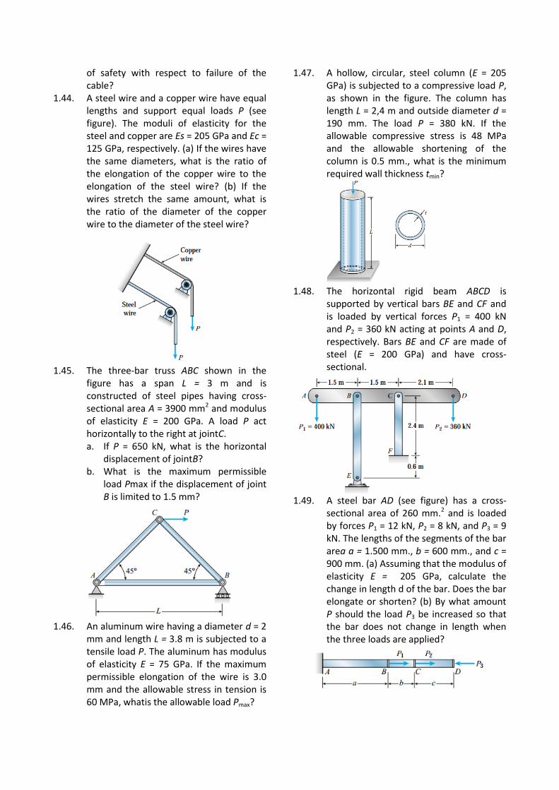
1.44. A steel wire and a copper wire have equal lengths and support equal loads P (see figure). The moduli of elasticity for the steel and copper are Es = 205 GPa and Ec = 125 GPa, respectively. (a) If the wires have the same diameters, what is the ratio of the elongation of the copper wire to the elongation of the steel wire? (b) If the wires stretch the same amount, what is the ratio of the diameter of the copper wire to the diameter of the steel wire?
1.45. The three-bar truss ABC shown in the
figure has a span L = 3 m and is constructed of steel pipes having cross-sectional area A = 3900 mm2 and modulus of elasticity E = 200 GPa. A load P act horizontally to the right at jointC. a. If P = 650 kN, what is the horizontal
displacement of jointB? b. What is the maximum permissible
load Pmax if the displacement of joint B is limited to 1.5 mm?
1.46. An aluminum wire having a diameter d = 2
mm and length L = 3.8 m is subjected to a tensile load P. The aluminum has modulus of elasticity E = 75 GPa. If the maximum permissible elongation of the wire is 3.0 mm and the allowable stress in tension is 60 MPa, whatis the allowable load Pmax?
1.47. A hollow, circular, steel column (E = 205 GPa) is subjected to a compressive load P, as shown in the figure. The column has length L = 2,4 m and outside diameter d = 190 mm. The load P = 380 kN. If the allowable compressive stress is 48 MPa and the allowable shortening of the column is 0.5 mm., what is the minimum required wall thickness tmin?
1.48. The horizontal rigid beam ABCD is
supported by vertical bars BE and CF and is loaded by vertical forces P1 = 400 kN and P2 = 360 kN acting at points A and D, respectively. Bars BE and CF are made of steel (E = 200 GPa) and have cross-sectional.
1.49. A steel bar AD (see figure) has a cross-
sectional area of 260 mm.2 and is loaded by forces P1 = 12 kN, P2 = 8 kN, and P3 = 9 kN. The lengths of the segments of the bar area a = 1.500 mm., b = 600 mm., and c = 900 mm. (a) Assuming that the modulus of elasticity E = 205 GPa, calculate the change in length d of the bar. Does the bar elongate or shorten? (b) By what amount P should the load P3 be increased so that the bar does not change in length when the three loads are applied?
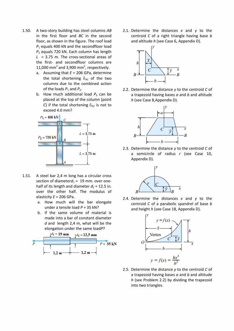
1.50. A two-story building has steel columns AB in the first floor and BC in the second floor, as shown in the figure. The roof load P1 equals 400 kN and the secondfloor load P2 equals 720 kN. Each column has length L = 3.75 m. The cross-sectional areas of the first- and secondfloor columns are 11,000 mm2 and 3,900 mm2, respectively. a. Assuming that E = 206 GPa, determine
the total shortening AC of the two columns due to the combined action of the loads P1 and P2.
b. How much additional load P0 can be placed at the top of the column (point
C) if the total shortening AC is not to exceed 4.0 mm?
1.51. A steel bar 2,4 m long has a circular cross section of diameterd1 = 19 mm. over one-half of its length and diameter d2 = 12.5 in. over the other half. The modulus of elasticity E = 206 GPa. a. How much will the bar elongate
under a tensile load P = 35 kN? b. If the same volume of material is
made into a bar of constant diameter d and length 2,4 m, what will be the elongation under the same loadP?
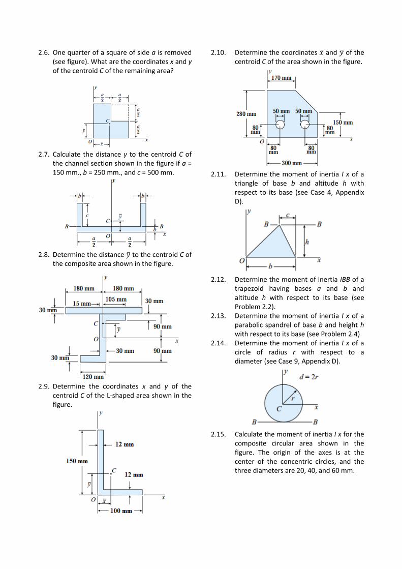
2.1. Determine the distances x and y to the centroid C of a right triangle having base b and altitude h (see Case 6, Appendix D).
2.2. Determine the distance y to the centroid C of
a trapezoid having bases a and b and altitude h (see Case 8,Appendix D).
2.3. Determine the distance y to the centroid C of
a semicircle of radius r (see Case 10, Appendix D).
2.4. Determine the distances x and y to the
centroid C of a parabolic spandrel of base b and height h (see Case 18, Appendix D).
2.5. Determine the distance y to the centroid C of
a trapezoid having bases a and b and altitude h (see Problem 2.2) by dividing the trapezoid into two triangles.
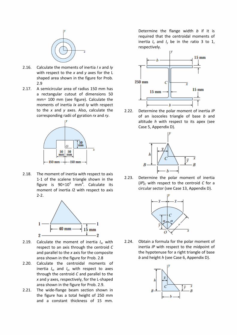
2.6. One quarter of a square of side a is removed (see figure). What are the coordinates x and y of the centroid C of the remaining area?
2.7. Calculate the distance y to the centroid C of
the channel section shown in the figure if a = 150 mm., b = 250 mm., and c = 500 mm.
2.8. Determine the distance �̅� to the centroid C of
the composite area shown in the figure.
2.9. Determine the coordinates x and y of the
centroid C of the L-shaped area shown in the figure.
2.10. Determine the coordinates �̅� and �̅� of the centroid C of the area shown in the figure.
2.11. Determine the moment of inertia I x of a
triangle of base b and altitude h with respect to its base (see Case 4, Appendix D).
2.12. Determine the moment of inertia IBB of a
trapezoid having bases a and b and altitude h with respect to its base (see Problem 2.2).
2.13. Determine the moment of inertia I x of a parabolic spandrel of base b and height h with respect to its base (see Problem 2.4)
2.14. Determine the moment of inertia I x of a circle of radius r with respect to a diameter (see Case 9, Appendix D).
2.15. Calculate the moment of inertia I x for the
composite circular area shown in the figure. The origin of the axes is at the center of the concentric circles, and the three diameters are 20, 40, and 60 mm.
2.16. Calculate the moments of inertia I x and Iy
with respect to the x and y axes for the L shaped area shown in the figure for Prob. 2.9
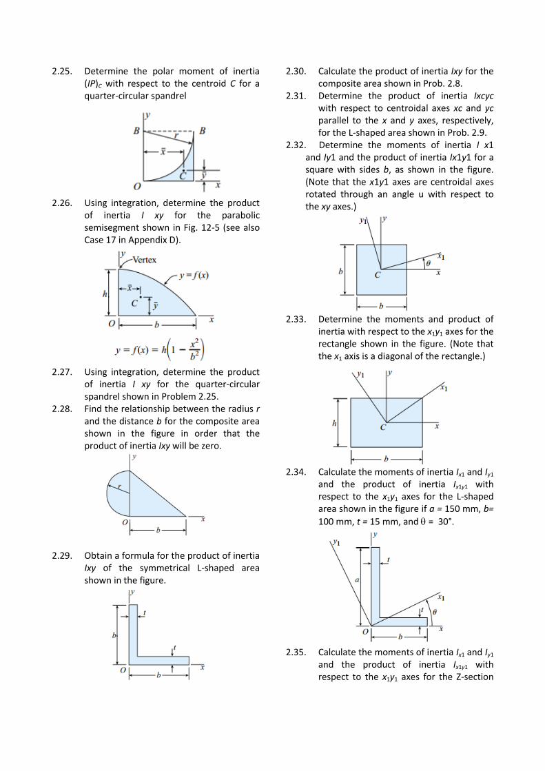
2.17. A semicircular area of radius 150 mm has a rectangular cutout of dimensions 50 mm× 100 mm (see figure). Calculate the moments of inertia Ix and Iy with respect to the x and y axes. Also, calculate the corresponding radii of gyration rx and ry.
2.18. The moment of inertia with respect to axis
1-1 of the scalene triangle shown in the figure is 90×103 mm4. Calculate its moment of inertia I2 with respect to axis 2-2.
2.19. Calculate the moment of inertia Ixc with
respect to an axis through the centroid C and parallel to the x axis for the composite area shown in the figure for Prob. 2.8
2.20. Calculate the centroidal moments of inertia Ixc and Iyc with respect to axes through the centroid C and parallel to the x and y axes, respectively, for the L-shaped area shown in the figure for Prob. 2.9.
2.21. The wide-flange beam section shown in the figure has a total height of 250 mm and a constant thickness of 15 mm.
Determine the flange width b if it is required that the centroidal moments of inertia Ix and Iy be in the ratio 3 to 1, respectively.
2.22. Determine the polar moment of inertia IP
of an isosceles triangle of base b and altitude h with respect to its apex (see Case 5, Appendix D).
2.23. Determine the polar moment of inertia
(IP)C with respect to the centroid C for a circular sector (see Case 13, Appendix D).
2.24. Obtain a formula for the polar moment of
inertia IP with respect to the midpoint of the hypotenuse for a right triangle of base b and height h (see Case 6, Appendix D).
2.25. Determine the polar moment of inertia (IP)C with respect to the centroid C for a quarter-circular spandrel
2.26. Using integration, determine the product
of inertia I xy for the parabolic semisegment shown in Fig. 12-5 (see also Case 17 in Appendix D).
2.27. Using integration, determine the product
of inertia I xy for the quarter-circular spandrel shown in Problem 2.25.
2.28. Find the relationship between the radius r and the distance b for the composite area shown in the figure in order that the product of inertia Ixy will be zero.
2.29. Obtain a formula for the product of inertia
Ixy of the symmetrical L-shaped area shown in the figure.
2.30. Calculate the product of inertia Ixy for the composite area shown in Prob. 2.8.
2.31. Determine the product of inertia Ixcyc with respect to centroidal axes xc and yc parallel to the x and y axes, respectively, for the L-shaped area shown in Prob. 2.9.
2.32. Determine the moments of inertia I x1 and Iy1 and the product of inertia Ix1y1 for a square with sides b, as shown in the figure. (Note that the x1y1 axes are centroidal axes rotated through an angle u with respect to the xy axes.)
2.33. Determine the moments and product of
inertia with respect to the x1y1 axes for the rectangle shown in the figure. (Note that the x1 axis is a diagonal of the rectangle.)
2.34. Calculate the moments of inertia Ix1 and Iy1
and the product of inertia Ix1y1 with respect to the x1y1 axes for the L-shaped area shown in the figure if a = 150 mm, b=
100 mm, t = 15 mm, and = 30°.
2.35. Calculate the moments of inertia Ix1 and Iy1
and the product of inertia Ix1y1 with respect to the x1y1 axes for the Z-section
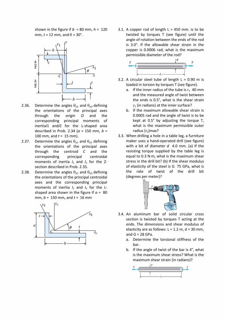
shown in the figure if b = 80 mm, h = 120
mm, t = 12 mm, and = 30°.
2.36. Determine the angles p1 and p2 defining
the orientations of the principal axes through the origin O and the corresponding principal moments of inertiaI1 andI2 for the L-shaped area described in Prob. 2.34 (a = 150 mm, b = 100 mm, and t = 15 mm).
2.37. Determine the angles p1 and p2 defining the orientations of the principal axes through the centroid C and the corresponding principal centroidal moments of inertia I1 and I2 for the Z-section described in Prob. 2.35.
2.38. Determine the angles p1 and p2 defining the orientations of the principal centroidal axes and the corresponding principal moments of inertia I1 and I2 for the L-shaped area shown in the figure if a = 80 mm, b = 150 mm, and t = 16 mm
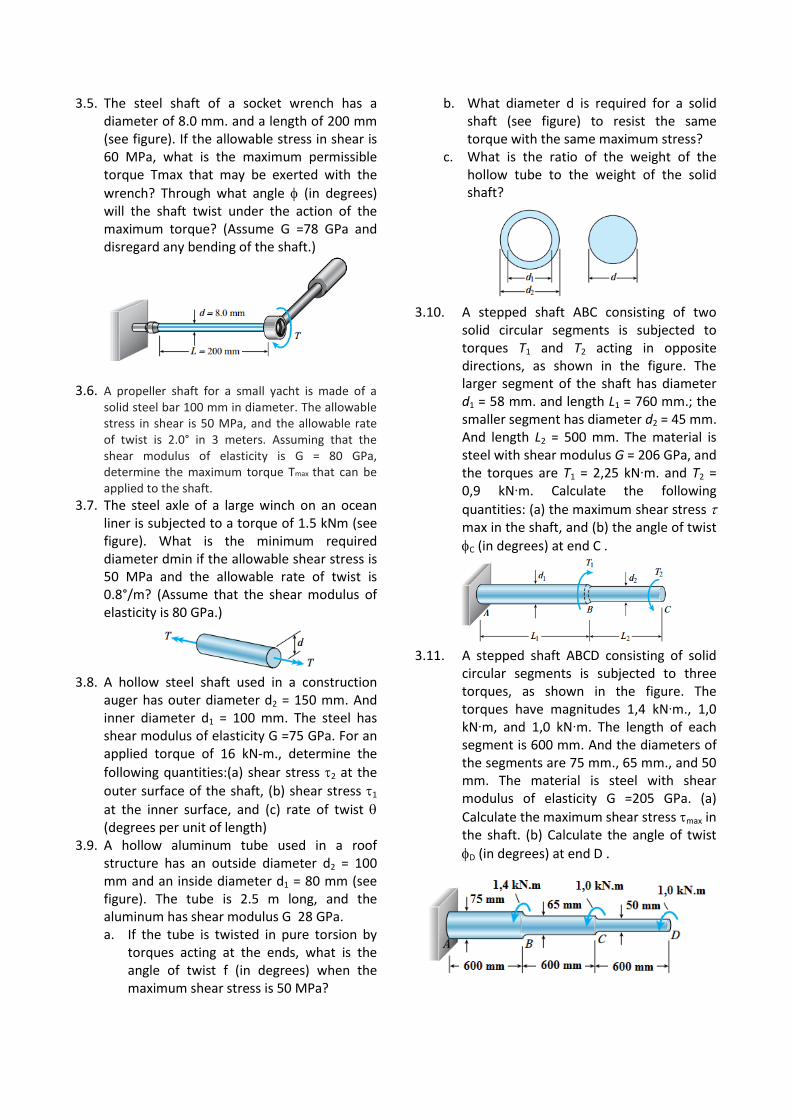
3.1. A copper rod of length L = 450 mm. is to be twisted by torques T (see figure) until the angle of rotation between the ends of the rod is 3.0°. If the allowable shear strain in the copper is 0.0006 rad, what is the maximum permissible diameter of the rod?
3.2. A circular steel tube of length L = 0.90 m is
loaded in torsion by torques T (see figure). a. If the inner radius of the tube is r1 40 mm
and the measured angle of twist between the ends is 0.5°, what is the shear strain
1 (in radians) at the inner surface? b. If the maximum allowable shear strain is
0.0005 rad and the angle of twist is to be kept at 0.5° by adjusting the torque T, what is the maximum permissible outer radius (r2)max?
3.3. When drilling a hole in a table leg, a furniture maker uses a hand-operated drill (see figure) with a bit of diameter d 4.0 mm. (a) If the resisting torque supplied by the table leg is equal to 0.3 N∙m, what is the maximum shear stress in the drill bit? (b) If the shear modulus of elasticity of the steel is G 75 GPa, what is the rate of twist of the drill bit (degrees per meter)?
3.4. An aluminum bar of solid circular cross
section is twisted by torques T acting at the ends. The dimensions and shear modulus of elasticity are as follows: L = 1.2 m, d = 30 mm, and G = 28 GPa. a. Determine the torsional stiffness of the
bar. b. If the angle of twist of the bar is 4°, what
is the maximum shear stress? What is the maximum shear strain (in radians)?
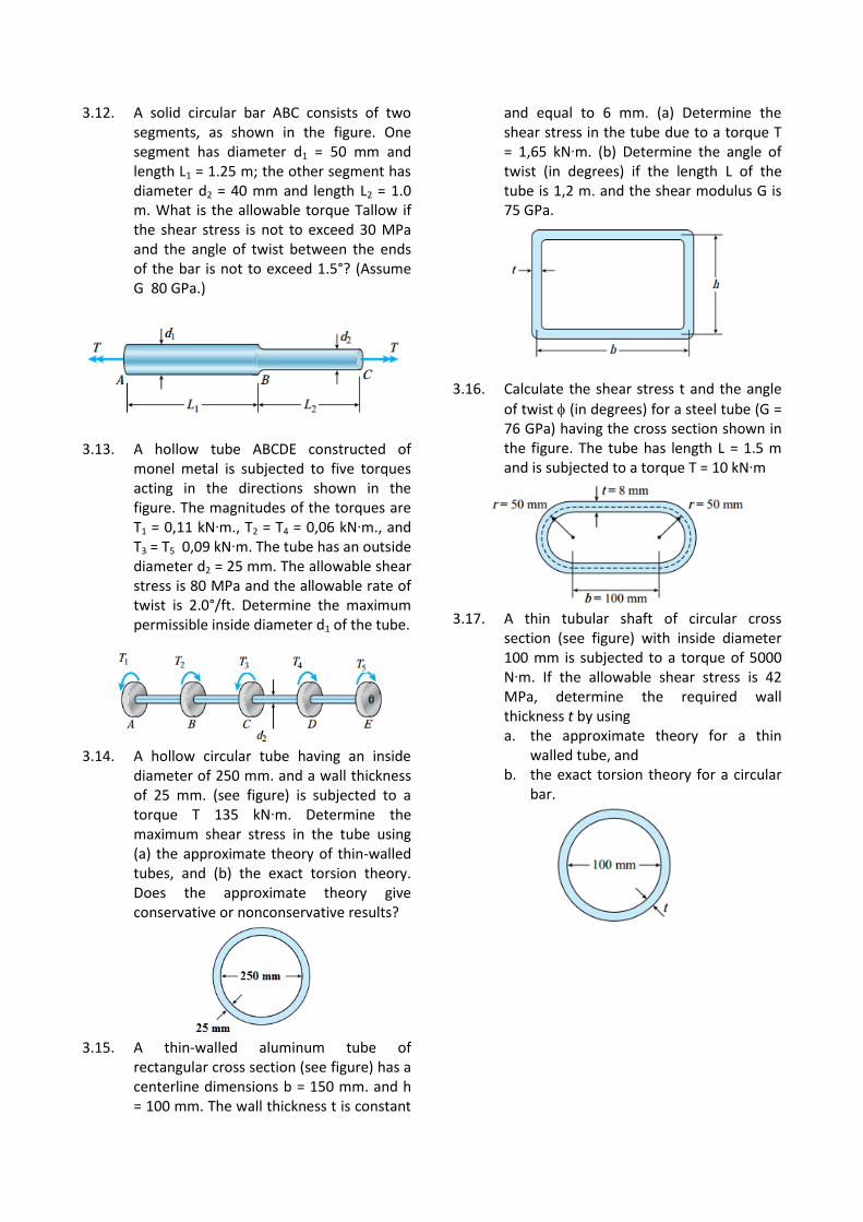
3.5. The steel shaft of a socket wrench has a diameter of 8.0 mm. and a length of 200 mm (see figure). If the allowable stress in shear is 60 MPa, what is the maximum permissible torque Tmax that may be exerted with the
wrench? Through what angle (in degrees) will the shaft twist under the action of the maximum torque? (Assume G =78 GPa and disregard any bending of the shaft.)
3.6. A propeller shaft for a small yacht is made of a solid steel bar 100 mm in diameter. The allowable stress in shear is 50 MPa, and the allowable rate of twist is 2.0° in 3 meters. Assuming that the shear modulus of elasticity is G = 80 GPa, determine the maximum torque Tmax that can be applied to the shaft.
3.7. The steel axle of a large winch on an ocean liner is subjected to a torque of 1.5 kNm (see figure). What is the minimum required diameter dmin if the allowable shear stress is 50 MPa and the allowable rate of twist is 0.8°/m? (Assume that the shear modulus of elasticity is 80 GPa.)
3.8. A hollow steel shaft used in a construction
auger has outer diameter d2 = 150 mm. And inner diameter d1 = 100 mm. The steel has shear modulus of elasticity G =75 GPa. For an applied torque of 16 kN-m., determine the
following quantities:(a) shear stress 2 at the
outer surface of the shaft, (b) shear stress 1
at the inner surface, and (c) rate of twist (degrees per unit of length)
3.9. A hollow aluminum tube used in a roof structure has an outside diameter d2 = 100 mm and an inside diameter d1 = 80 mm (see figure). The tube is 2.5 m long, and the aluminum has shear modulus G 28 GPa. a. If the tube is twisted in pure torsion by
torques acting at the ends, what is the angle of twist f (in degrees) when the maximum shear stress is 50 MPa?
b. What diameter d is required for a solid shaft (see figure) to resist the same torque with the same maximum stress?
c. What is the ratio of the weight of the hollow tube to the weight of the solid shaft?
3.10. A stepped shaft ABC consisting of two
solid circular segments is subjected to torques T1 and T2 acting in opposite directions, as shown in the figure. The larger segment of the shaft has diameter d1 = 58 mm. and length L1 = 760 mm.; the smaller segment has diameter d2 = 45 mm. And length L2 = 500 mm. The material is steel with shear modulus G = 206 GPa, and the torques are T1 = 2,25 kN∙m. and T2 = 0,9 kN∙m. Calculate the following
quantities: (a) the maximum shear stress max in the shaft, and (b) the angle of twist
C (in degrees) at end C .
3.11. A stepped shaft ABCD consisting of solid
circular segments is subjected to three torques, as shown in the figure. The torques have magnitudes 1,4 kN∙m., 1,0 kN∙m, and 1,0 kN∙m. The length of each segment is 600 mm. And the diameters of the segments are 75 mm., 65 mm., and 50 mm. The material is steel with shear modulus of elasticity G =205 GPa. (a)
Calculate the maximum shear stress max in the shaft. (b) Calculate the angle of twist
D (in degrees) at end D .
3.12. A solid circular bar ABC consists of two segments, as shown in the figure. One segment has diameter d1 = 50 mm and length L1 = 1.25 m; the other segment has diameter d2 = 40 mm and length L2 = 1.0 m. What is the allowable torque Tallow if the shear stress is not to exceed 30 MPa and the angle of twist between the ends of the bar is not to exceed 1.5°? (Assume G 80 GPa.)
3.13. A hollow tube ABCDE constructed of
monel metal is subjected to five torques acting in the directions shown in the figure. The magnitudes of the torques are T1 = 0,11 kN∙m., T2 = T4 = 0,06 kN∙m., and T3 = T5 0,09 kN∙m. The tube has an outside diameter d2 = 25 mm. The allowable shear stress is 80 MPa and the allowable rate of twist is 2.0°/ft. Determine the maximum permissible inside diameter d1 of the tube.
3.14. A hollow circular tube having an inside
diameter of 250 mm. and a wall thickness of 25 mm. (see figure) is subjected to a torque T 135 kN∙m. Determine the maximum shear stress in the tube using (a) the approximate theory of thin-walled tubes, and (b) the exact torsion theory. Does the approximate theory give conservative or nonconservative results?
3.15. A thin-walled aluminum tube of
rectangular cross section (see figure) has a centerline dimensions b = 150 mm. and h = 100 mm. The wall thickness t is constant
and equal to 6 mm. (a) Determine the shear stress in the tube due to a torque T = 1,65 kN∙m. (b) Determine the angle of twist (in degrees) if the length L of the tube is 1,2 m. and the shear modulus G is 75 GPa.
3.16. Calculate the shear stress t and the angle
of twist (in degrees) for a steel tube (G = 76 GPa) having the cross section shown in the figure. The tube has length L = 1.5 m and is subjected to a torque T = 10 kN∙m
3.17. A thin tubular shaft of circular cross
section (see figure) with inside diameter 100 mm is subjected to a torque of 5000 N∙m. If the allowable shear stress is 42 MPa, determine the required wall thickness t by using a. the approximate theory for a thin
walled tube, and b. the exact torsion theory for a circular
bar.
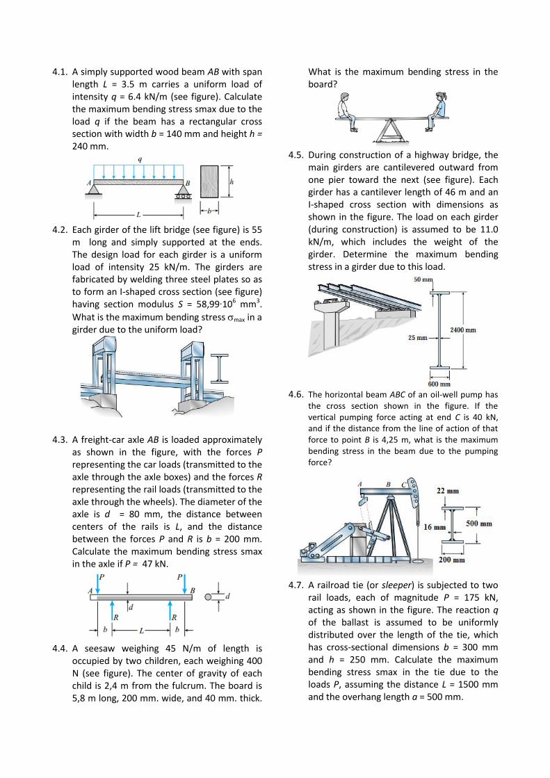
4.1. A simply supported wood beam AB with span length L = 3.5 m carries a uniform load of intensity q = 6.4 kN/m (see figure). Calculate the maximum bending stress smax due to the load q if the beam has a rectangular cross section with width b = 140 mm and height h = 240 mm.
4.2. Each girder of the lift bridge (see figure) is 55
m long and simply supported at the ends. The design load for each girder is a uniform load of intensity 25 kN/m. The girders are fabricated by welding three steel plates so as to form an I-shaped cross section (see figure) having section modulus S = 58,99∙106 mm3.
What is the maximum bending stress max in a girder due to the uniform load?
4.3. A freight-car axle AB is loaded approximately
as shown in the figure, with the forces P representing the car loads (transmitted to the axle through the axle boxes) and the forces R representing the rail loads (transmitted to the axle through the wheels). The diameter of the axle is d = 80 mm, the distance between centers of the rails is L, and the distance between the forces P and R is b = 200 mm. Calculate the maximum bending stress smax in the axle if P = 47 kN.
4.4. A seesaw weighing 45 N/m of length is
occupied by two children, each weighing 400 N (see figure). The center of gravity of each child is 2,4 m from the fulcrum. The board is 5,8 m long, 200 mm. wide, and 40 mm. thick.
What is the maximum bending stress in the board?
4.5. During construction of a highway bridge, the
main girders are cantilevered outward from one pier toward the next (see figure). Each girder has a cantilever length of 46 m and an I-shaped cross section with dimensions as shown in the figure. The load on each girder (during construction) is assumed to be 11.0 kN/m, which includes the weight of the girder. Determine the maximum bending stress in a girder due to this load.
4.6. The horizontal beam ABC of an oil-well pump has
the cross section shown in the figure. If the vertical pumping force acting at end C is 40 kN, and if the distance from the line of action of that force to point B is 4,25 m, what is the maximum bending stress in the beam due to the pumping force?
4.7. A railroad tie (or sleeper) is subjected to two
rail loads, each of magnitude P = 175 kN, acting as shown in the figure. The reaction q of the ballast is assumed to be uniformly distributed over the length of the tie, which has cross-sectional dimensions b = 300 mm and h = 250 mm. Calculate the maximum bending stress smax in the tie due to the loads P, assuming the distance L = 1500 mm and the overhang length a = 500 mm.
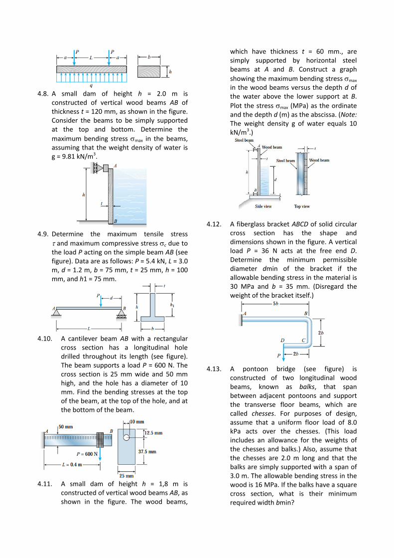
4.8. A small dam of height h = 2.0 m is
constructed of vertical wood beams AB of thickness t = 120 mm, as shown in the figure. Consider the beams to be simply supported at the top and bottom. Determine the
maximum bending stress max in the beams, assuming that the weight density of water is g = 9.81 kN/m3.
4.9. Determine the maximum tensile stress
and maximum compressive stress c due to the load P acting on the simple beam AB (see figure). Data are as follows: P = 5.4 kN, L = 3.0 m, d = 1.2 m, b = 75 mm, t = 25 mm, h = 100 mm, and h1 = 75 mm.
4.10. A cantilever beam AB with a rectangular
cross section has a longitudinal hole drilled throughout its length (see figure). The beam supports a load P = 600 N. The cross section is 25 mm wide and 50 mm high, and the hole has a diameter of 10 mm. Find the bending stresses at the top of the beam, at the top of the hole, and at the bottom of the beam.
4.11. A small dam of height h = 1,8 m is
constructed of vertical wood beams AB, as shown in the figure. The wood beams,
which have thickness t = 60 mm., are simply supported by horizontal steel beams at A and B. Construct a graph
showing the maximum bending stress max in the wood beams versus the depth d of the water above the lower support at B.
Plot the stress max (MPa) as the ordinate and the depth d (m) as the abscissa. (Note: The weight density g of water equals 10 kN/m3.)
4.12. A fiberglass bracket ABCD of solid circular
cross section has the shape and dimensions shown in the figure. A vertical load P = 36 N acts at the free end D. Determine the minimum permissible diameter dmin of the bracket if the allowable bending stress in the material is 30 MPa and b = 35 mm. (Disregard the weight of the bracket itself.)
4.13. A pontoon bridge (see figure) is
constructed of two longitudinal wood beams, known as balks, that span between adjacent pontoons and support the transverse floor beams, which are called chesses. For purposes of design, assume that a uniform floor load of 8.0 kPa acts over the chesses. (This load includes an allowance for the weights of the chesses and balks.) Also, assume that the chesses are 2.0 m long and that the balks are simply supported with a span of 3.0 m. The allowable bending stress in the wood is 16 MPa. If the balks have a square cross section, what is their minimum required width bmin?
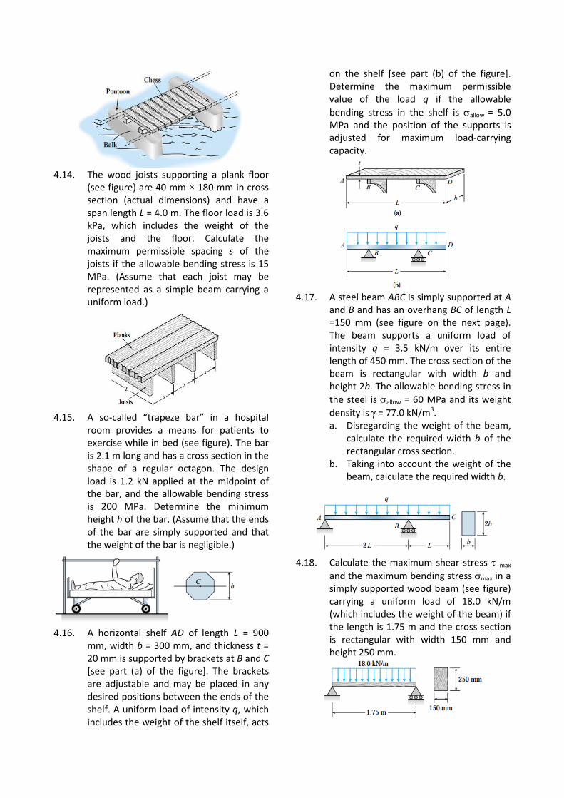
4.14. The wood joists supporting a plank floor
(see figure) are 40 mm × 180 mm in cross section (actual dimensions) and have a span length L = 4.0 m. The floor load is 3.6 kPa, which includes the weight of the joists and the floor. Calculate the maximum permissible spacing s of the joists if the allowable bending stress is 15 MPa. (Assume that each joist may be represented as a simple beam carrying a uniform load.)
4.15. A so-called “trapeze bar” in a hospital
room provides a means for patients to exercise while in bed (see figure). The bar is 2.1 m long and has a cross section in the shape of a regular octagon. The design load is 1.2 kN applied at the midpoint of the bar, and the allowable bending stress is 200 MPa. Determine the minimum height h of the bar. (Assume that the ends of the bar are simply supported and that the weight of the bar is negligible.)
4.16. A horizontal shelf AD of length L = 900
mm, width b = 300 mm, and thickness t = 20 mm is supported by brackets at B and C [see part (a) of the figure]. The brackets are adjustable and may be placed in any desired positions between the ends of the shelf. A uniform load of intensity q, which includes the weight of the shelf itself, acts
on the shelf [see part (b) of the figure]. Determine the maximum permissible value of the load q if the allowable
bending stress in the shelf is allow = 5.0 MPa and the position of the supports is adjusted for maximum load-carrying capacity.
4.17. A steel beam ABC is simply supported at A
and B and has an overhang BC of length L =150 mm (see figure on the next page). The beam supports a uniform load of intensity q = 3.5 kN/m over its entire length of 450 mm. The cross section of the beam is rectangular with width b and height 2b. The allowable bending stress in
the steel is allow = 60 MPa and its weight
density is = 77.0 kN/m3. a. Disregarding the weight of the beam,
calculate the required width b of the rectangular cross section.
b. Taking into account the weight of the beam, calculate the required width b.
4.18. Calculate the maximum shear stress max
and the maximum bending stress max in a simply supported wood beam (see figure) carrying a uniform load of 18.0 kN/m (which includes the weight of the beam) if the length is 1.75 m and the cross section is rectangular with width 150 mm and height 250 mm.
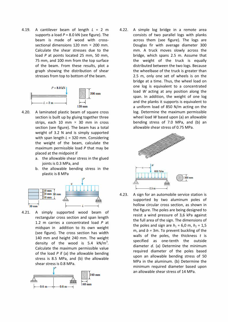
4.19. A cantilever beam of length L = 2 m supports a load P = 8.0 kN (see figure). The beam is made of wood with cross-sectional dimensions 120 mm × 200 mm. Calculate the shear stresses due to the load P at points located 25 mm, 50 mm, 75 mm, and 100 mm from the top surface of the beam. From these results, plot a graph showing the distribution of shear stresses from top to bottom of the beam.
4.20. A laminated plastic beam of square cross
section is built up by gluing together three strips, each 10 mm × 30 mm in cross section (see figure). The beam has a total weight of 3.2 N and is simply supported with span length L = 320 mm. Considering the weight of the beam, calculate the maximum permissible load P that may be placed at the midpoint if a. the allowable shear stress in the glued
joints is 0.3 MPa, and b. the allowable bending stress in the
plastic is 8 MPa
4.21. A simply supported wood beam of
rectangular cross section and span length 1.2 m carries a concentrated load P at midspan in addition to its own weight (see figure). The cross section has width 140 mm and height 240 mm. The weight density of the wood is 5.4 kN/m3. Calculate the maximum permissible value of the load P if (a) the allowable bending stress is 8.5 MPa, and (b) the allowable shear stress is 0.8 MPa.
4.22. A simple log bridge in a remote area consists of two parallel logs with planks across them (see figure). The logs are Douglas fir with average diameter 300 mm. A truck moves slowly across the bridge, which spans 2.5 m. Assume that the weight of the truck is equally distributed between the two logs. Because the wheelbase of the truck is greater than 2.5 m, only one set of wheels is on the bridge at a time. Thus, the wheel load on one log is equivalent to a concentrated load W acting at any position along the span. In addition, the weight of one log and the planks it supports is equivalent to a uniform load of 850 N/m acting on the log. Determine the maximum permissible wheel load W based upon (a) an allowable bending stress of 7.0 MPa, and (b) an allowable shear stress of 0.75 MPa.
4.23. A sign for an automobile service station is
supported by two aluminum poles of hollow circular cross section, as shown in the figure. The poles are being designed to resist a wind pressure of 3,6 kPa against the full area of the sign. The dimensions of the poles and sign are h1 = 6,0 m, h2 = 1,5 m, and b = 3m. To prevent buckling of the walls of the poles, the thickness t is specified as one-tenth the outside diameter d. (a) Determine the minimum required diameter of the poles based upon an allowable bending stress of 50 MPa in the aluminum. (b) Determine the minimum required diameter based upon an allowable shear stress of 14 MPa.
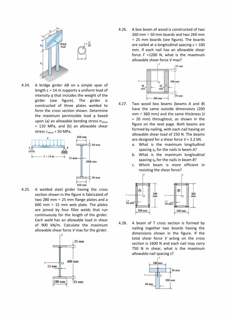
4.24. A bridge girder AB on a simple span of
length L = 14 m supports a uniform load of intensity q that includes the weight of the girder (see figure). The girder is constructed of three plates welded to form the cross section shown. Determine the maximum permissible load q based
upon (a) an allowable bending stress allow = 110 MPa, and (b) an allowable shear
stress allow = 50 MPa.
4.25. A welded steel girder having the cross
section shown in the figure is fabricated of two 280 mm × 25 mm flange plates and a 600 mm × 15 mm web plate. The plates are joined by four fillet welds that run continuously for the length of the girder. Each weld has an allowable load in shear of 900 kN/m. Calculate the maximum allowable shear force V max for the girder.
4.26. A box beam of wood is constructed of two 260 mm × 50 mm boards and two 260 mm × 25 mm boards (see figure). The boards are nailed at a longitudinal spacing s = 100 mm. If each nail has an allowable shear force F =1200 N, what is the maximum allowable shear force V max?
4.27. Two wood box beams (beams A and B)
have the same outside dimensions (200 mm × 360 mm) and the same thickness (t = 20 mm) throughout, as shown in the figure on the next page. Both beams are formed by nailing, with each nail having an allowable shear load of 250 N. The beams are designed for a shear force V = 3.2 kN. a. What is the maximum longitudinal
spacing sA for the nails in beam A? b. What is the maximum longitudinal
spacing sB for the nails in beam B? c. Which beam is more efficient in
resisting the shear force?
4.28. A beam of T cross section is formed by
nailing together two boards having the dimensions shown in the figure. If the total shear force V acting on the cross section is 1600 N and each nail may carry 750 N in shear, what is the maximum allowable nail spacing s?
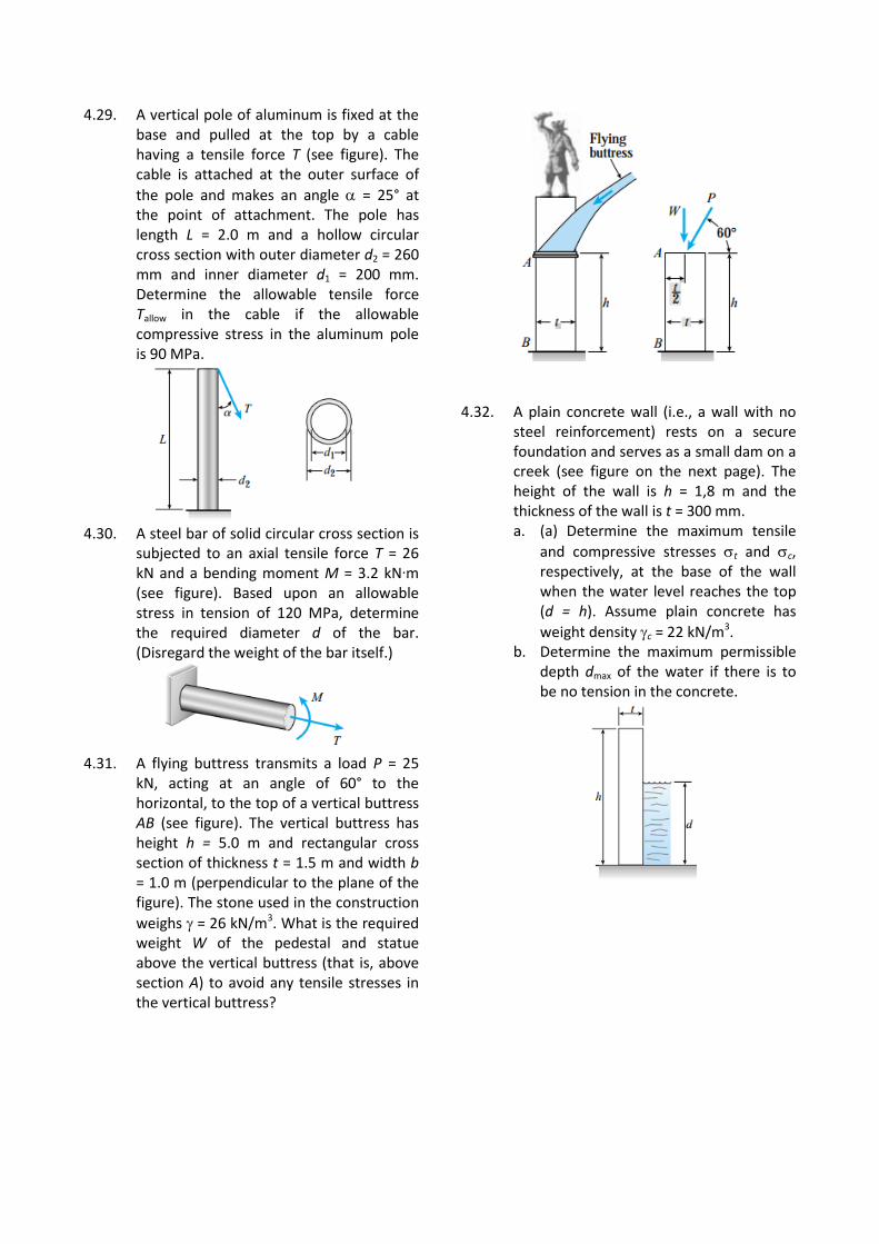
4.29. A vertical pole of aluminum is fixed at the base and pulled at the top by a cable having a tensile force T (see figure). The cable is attached at the outer surface of
the pole and makes an angle = 25° at the point of attachment. The pole has length L = 2.0 m and a hollow circular cross section with outer diameter d2 = 260 mm and inner diameter d1 = 200 mm. Determine the allowable tensile force Tallow in the cable if the allowable compressive stress in the aluminum pole is 90 MPa.
4.30. A steel bar of solid circular cross section is
subjected to an axial tensile force T = 26 kN and a bending moment M = 3.2 kN∙m (see figure). Based upon an allowable stress in tension of 120 MPa, determine the required diameter d of the bar. (Disregard the weight of the bar itself.)
4.31. A flying buttress transmits a load P = 25
kN, acting at an angle of 60° to the horizontal, to the top of a vertical buttress AB (see figure). The vertical buttress has height h = 5.0 m and rectangular cross section of thickness t = 1.5 m and width b = 1.0 m (perpendicular to the plane of the figure). The stone used in the construction
weighs = 26 kN/m3. What is the required weight W of the pedestal and statue above the vertical buttress (that is, above section A) to avoid any tensile stresses in the vertical buttress?
4.32. A plain concrete wall (i.e., a wall with no steel reinforcement) rests on a secure foundation and serves as a small dam on a creek (see figure on the next page). The height of the wall is h = 1,8 m and the thickness of the wall is t = 300 mm. a. (a) Determine the maximum tensile
and compressive stresses t and c, respectively, at the base of the wall when the water level reaches the top (d = h). Assume plain concrete has
weight density c = 22 kN/m3. b. Determine the maximum permissible
depth dmax of the water if there is to be no tension in the concrete.
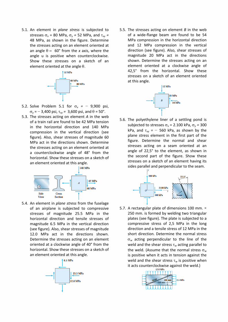
5.1. An element in plane stress is subjected to
stresses x = 80 MPa, y = 52 MPa, and xy = 48 MPa, as shown in the figure. Determine the stresses acting on an element oriented at
an angle 60° from the x axis, where the angle u is positive when counterclockwise. Show these stresses on a sketch of an
element oriented at the angle .
5.2. Solve Problem 5.1 for x = − 9,900 psi,
y = − 3,400 psi, xy = 3,600 psi, and = 50°. 5.3. The stresses acting on element A in the web
of a train rail are found to be 42 MPa tension in the horizontal direction and 140 MPa compression in the vertical direction (see figure). Also, shear stresses of magnitude 60 MPa act in the directions shown. Determine the stresses acting on an element oriented at a counterclockwise angle of 48° from the horizontal. Show these stresses on a sketch of an element oriented at this angle.
5.4. An element in plane stress from the fuselage
of an airplane is subjected to compressive stresses of magnitude 25.5 MPa in the horizontal direction and tensile stresses of magnitude 6.5 MPa in the vertical direction (see figure). Also, shear stresses of magnitude 12.0 MPa act in the directions shown. Determine the stresses acting on an element oriented at a clockwise angle of 40° from the horizontal. Show these stresses on a sketch of an element oriented at this angle.
5.5. The stresses acting on element B in the web of a wide-flange beam are found to be 54 MPa compression in the horizontal direction and 12 MPa compression in the vertical direction (see figure). Also, shear stresses of magnitude 20 MPa act in the directions shown. Determine the stresses acting on an element oriented at a clockwise angle of 42,5° from the horizontal. Show these stresses on a sketch of an element oriented at this angle.
5.6. The polyethylene liner of a settling pond is
subjected to stresses x = 2.100 kPa, y = 300
kPa, and xy = − 560 kPa, as shown by the plane stress element in the first part of the figure. Determine the normal and shear stresses acting on a seam oriented at an angle of 22,5° to the element, as shown in the second part of the figure. Show these stresses on a sketch of an element having its sides parallel and perpendicular to the seam.
5.7. A rectangular plate of dimensions 100 mm. ×
250 mm. is formed by welding two triangular plates (see figure). The plate is subjected to a compressive stress of 2,5 MPa in the long direction and a tensile stress of 12 MPa in the short direction. Determine the normal stress
w acting perpendicular to the line of the
weld and the shear stress w acting parallel to
the weld. (Assume that the normal stress w
is positive when it acts in tension against the
weld and the shear stress w is positive when it acts counterclockwise against the weld.)
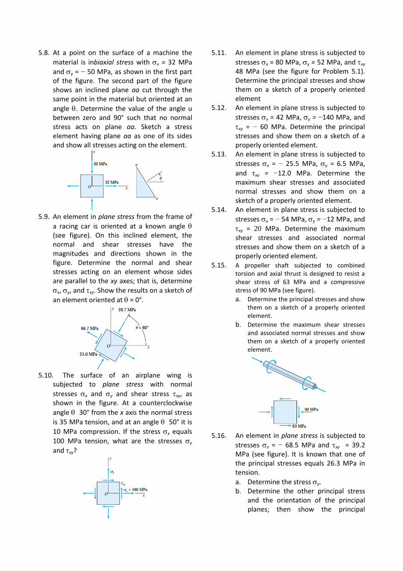
5.8. At a point on the surface of a machine the
material is inbiaxial stress with x = 32 MPa
and y = − 50 MPa, as shown in the first part of the figure. The second part of the figure shows an inclined plane aa cut through the same point in the material but oriented at an
angle . Determine the value of the angle u between zero and 90° such that no normal stress acts on plane aa. Sketch a stress element having plane aa as one of its sides and show all stresses acting on the element.
5.9. An element in plane stress from the frame of
a racing car is oriented at a known angle (see figure). On this inclined element, the normal and shear stresses have the magnitudes and directions shown in the figure. Determine the normal and shear stresses acting on an element whose sides are parallel to the xy axes; that is, determine
x, y, and xy. Show the results on a sketch of
an element oriented at = 0°.
5.10. The surface of an airplane wing is
subjected to plane stress with normal
stresses x and y and shear stress xy, as shown in the figure. At a counterclockwise
angle 30° from the x axis the normal stress
is 35 MPa tension, and at an angle 50° it is
10 MPa compression. If the stress x equals
100 MPa tension, what are the stresses y
and xy?
5.11. An element in plane stress is subjected to
stresses x = 80 MPa, y = 52 MPa, and xy 48 MPa (see the figure for Problem 5.1). Determine the principal stresses and show them on a sketch of a properly oriented element
5.12. An element in plane stress is subjected to
stresses x = 42 MPa, y = −140 MPa, and
xy = − 60 MPa. Determine the principal stresses and show them on a sketch of a properly oriented element.
5.13. An element in plane stress is subjected to
stresses x = − 25.5 MPa, y = 6.5 MPa,
and xy = −12.0 MPa. Determine the maximum shear stresses and associated normal stresses and show them on a sketch of a properly oriented element.
5.14. An element in plane stress is subjected to
stresses x = − 54 MPa, y = −12 MPa, and
xy = 20 MPa. Determine the maximum shear stresses and associated normal stresses and show them on a sketch of a properly oriented element.
5.15. A propeller shaft subjected to combined torsion and axial thrust is designed to resist a shear stress of 63 MPa and a compressive stress of 90 MPa (see figure). a. Determine the principal stresses and show
them on a sketch of a properly oriented element.
b. Determine the maximum shear stresses and associated normal stresses and show them on a sketch of a properly oriented element.
5.16. An element in plane stress is subjected to
stresses x = − 68.5 MPa and xy = 39.2 MPa (see figure). It is known that one of the principal stresses equals 26.3 MPa in tension.
a. Determine the stress y. b. Determine the other principal stress
and the orientation of the principal planes; then show the principal
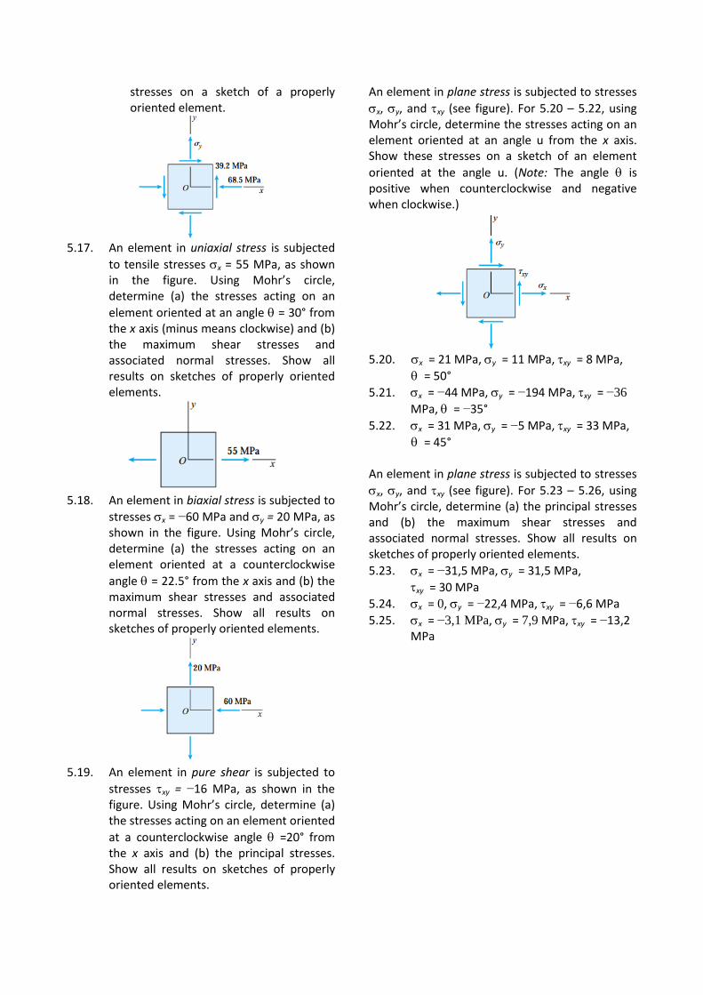
stresses on a sketch of a properly oriented element.
5.17. An element in uniaxial stress is subjected
to tensile stresses x = 55 MPa, as shown in the figure. Using Mohr’s circle, determine (a) the stresses acting on an
element oriented at an angle = 30° from the x axis (minus means clockwise) and (b) the maximum shear stresses and associated normal stresses. Show all results on sketches of properly oriented elements.
5.18. An element in biaxial stress is subjected to
stresses x = −60 MPa and y = 20 MPa, as shown in the figure. Using Mohr’s circle, determine (a) the stresses acting on an element oriented at a counterclockwise
angle = 22.5° from the x axis and (b) the maximum shear stresses and associated normal stresses. Show all results on sketches of properly oriented elements.
5.19. An element in pure shear is subjected to
stresses xy = −16 MPa, as shown in the figure. Using Mohr’s circle, determine (a) the stresses acting on an element oriented
at a counterclockwise angle =20° from the x axis and (b) the principal stresses. Show all results on sketches of properly oriented elements.
An element in plane stress is subjected to stresses
x, y, and xy (see figure). For 5.20 – 5.22, using Mohr’s circle, determine the stresses acting on an element oriented at an angle u from the x axis. Show these stresses on a sketch of an element
oriented at the angle u. (Note: The angle is positive when counterclockwise and negative when clockwise.)
5.20. x = 21 MPa, y = 11 MPa, xy = 8 MPa,
= 50°
5.21. x = −44 MPa, y = −194 MPa, xy = −36
MPa, = −35°
5.22. x = 31 MPa, y = −5 MPa, xy = 33 MPa,
= 45° An element in plane stress is subjected to stresses
x, y, and xy (see figure). For 5.23 – 5.26, using Mohr’s circle, determine (a) the principal stresses and (b) the maximum shear stresses and associated normal stresses. Show all results on sketches of properly oriented elements.
5.23. x = −31,5 MPa, y = 31,5 MPa,
xy = 30 MPa
5.24. x = 0, y = −22,4 MPa, xy = −6,6 MPa
5.25. x = −3,1 MPa, y = 7,9 MPa, xy = −13,2 MPa
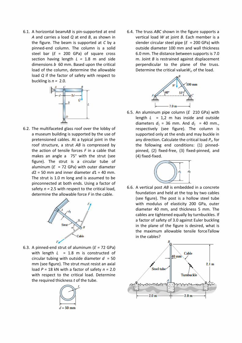
6.1. A horizontal beamAB is pin-supported at end A and carries a load Q at end B, as shown in the figure. The beam is supported at C by a pinned-end column. The column is a solid steel bar (E = 200 GPa) of square cross section having length L = 1.8 m and side dimensions b 60 mm. Based upon the critical load of the column, determine the allowable load Q if the factor of safety with respect to buckling is n = 2.0.
6.2. The multifaceted glass roof over the lobby of
a museum building is supported by the use of pretensioned cables. At a typical joint in the roof structure, a strut AB is compressed by the action of tensile forces F in a cable that makes an angle a 75° with the strut (see figure). The strut is a circular tube of aluminum (E = 72 GPa) with outer diameter d2 = 50 mm and inner diameter d1 = 40 mm. The strut is 1.0 m long and is assumed to be pinconnected at both ends. Using a factor of safety n = 2.5 with respect to the critical load, determine the allowable force F in the cable.
6.3. A pinned-end strut of aluminum (E = 72 GPa)
with length L = 1.8 m is constructed of circular tubing with outside diameter d = 50 mm (see figure). The strut must resist an axial load P = 18 kN with a factor of safety n = 2.0 with respect to the critical load. Determine the required thickness t of the tube.
6.4. The truss ABC shown in the figure supports a vertical load W at joint B. Each member is a slender circular steel pipe (E = 200 GPa) with outside diameter 100 mm and wall thickness 6.0 mm. The distance between supports is 7.0 m. Joint B is restrained against displacement perpendicular to the plane of the truss. Determine the critical valueWcr of the load.
6.5. An aluminum pipe column (E 210 GPa) with
length L = 1,2 m has inside and outside diameters d1 = 36 mm. And d2 = 40 mm., respectively (see figure). The column is supported only at the ends and may buckle in any direction. Calculate the critical load Pcr for the following end conditions: (1) pinned- pinned, (2) fixed-free, (3) fixed-pinned, and (4) fixed-fixed.
6.6. A vertical post AB is embedded in a concrete
foundation and held at the top by two cables (see figure). The post is a hollow steel tube with modulus of elasticity 200 GPa, outer diameter 40 mm, and thickness 5 mm. The cables are tightened equally by turnbuckles. If a factor of safety of 3.0 against Euler buckling in the plane of the figure is desired, what is the maximum allowable tensile forceTallow in the cables?
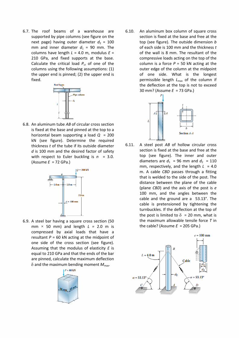
6.7. The roof beams of a warehouse are supported by pipe columns (see figure on the next page) having outer diameter d2 = 100 mm and inner diameter d1 = 90 mm. The columns have length L = 4.0 m, modulus E = 210 GPa, and fixed supports at the base. Calculate the critical load Pcr of one of the columns using the following assumptions: (1) the upper end is pinned; (2) the upper end is fixed.
6.8. An aluminum tube AB of circular cross section
is fixed at the base and pinned at the top to a horizontal beam supporting a load Q = 200 kN (see figure). Determine the required thickness t of the tube if its outside diameter d is 100 mm and the desired factor of safety with respect to Euler buckling is n = 3.0. (Assume E = 72 GPa.)
6.9. A steel bar having a square cross section (50
mm × 50 mm) and length L = 2.0 m is compressed by axial loads that have a resultant P = 60 kN acting at the midpoint of one side of the cross section (see figure). Assuming that the modulus of elasticity E is equal to 210 GPa and that the ends of the bar are pinned, calculate the maximum deflection
and the maximum bending moment Mmax.
6.10. An aluminum box column of square cross section is fixed at the base and free at the top (see figure). The outside dimension b of each side is 100 mm and the thickness t of the wall is 8 mm. The resultant of the compressive loads acting on the top of the column is a force P = 50 kN acting at the outer edge of the column at the midpoint of one side. What is the longest permissible length Lmax of the column if the deflection at the top is not to exceed 30 mm? (Assume E = 73 GPa.)
6.11. A steel post AB of hollow circular cross
section is fixed at the base and free at the top (see figure). The inner and outer diameters are d1 = 96 mm and d2 = 110 mm, respectively, and the length L = 4.0 m. A cable CBD passes through a fitting that is welded to the side of the post. The distance between the plane of the cable (plane CBD) and the axis of the post is e 100 mm, and the angles between the cable and the ground are a 53.13°. The cable is pretensioned by tightening the turnbuckles. If the deflection at the top of
the post is limited to = 20 mm, what is the maximum allowable tensile force T in the cable? (Assume E = 205 GPa.)
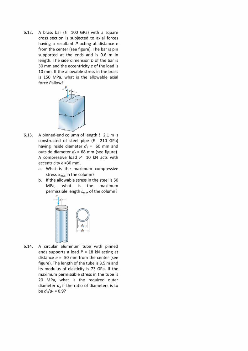
6.12. A brass bar (E 100 GPa) with a square cross section is subjected to axial forces having a resultant P acting at distance e from the center (see figure). The bar is pin supported at the ends and is 0.6 m in length. The side dimension b of the bar is 30 mm and the eccentricity e of the load is 10 mm. If the allowable stress in the brass is 150 MPa, what is the allowable axial force Pallow?
6.13. A pinned-end column of length L 2.1 m is
constructed of steel pipe (E 210 GPa) having inside diameter d1 = 60 mm and outside diameter d2 = 68 mm (see figure). A compressive load P 10 kN acts with eccentricity e =30 mm. a. What is the maximum compressive
stress max in the column? b. If the allowable stress in the steel is 50
MPa, what is the maximum permissible length Lmax of the column?
6.14. A circular aluminum tube with pinned
ends supports a load P = 18 kN acting at distance e = 50 mm from the center (see figure). The length of the tube is 3.5 m and its modulus of elasticity is 73 GPa. If the maximum permissible stress in the tube is 20 MPa, what is the required outer diameter d2 if the ratio of diameters is to be d1/d2 = 0.9?