Embed Size (px)
Citation preview
070-BCE-004 070-BCE-016
IOE, PULCHOWK CAMPUS
1 ABHASH ACHARYA
ANIL NEPAL
TRANSPORTATION
ENGINEERING - I (HILL ROADS)
Compiled and Prepared By:
Abhash Acharya (070-BCE-004)
Anil Nepal (070-BCE-016)
Central Campus, Pulchowk
070-BCE-004 070-BCE-016 IOE, PULCHOWK CAMPUS
2 ABHASH ACHARYA ANIL NEPAL
Hill Roads
5.1 Introduction
A hill road may be defined as the one which passes through a terrain with a cross slope of 25% or
more. There may be sections along hill roads with the cross slope less than 25%, especially when
the road follows a river route. Even then these sections are also referred to as hill roads. Hence, to
establish a hill road overall terrain must be taken into account.
The hilly regions generally have extremes of climatic conditions, difficult and hazardous terrains,
topography and vast high altitude areas. The region is sparsely populated and basic infrastructural
facilities available in plain terrain are absent. Hence, a strong stable and feasible road must be
present in hilly areas for overall development of other sectors as well.
Design and Construction Problems
Design and Construction of roads in hills and mountain are more complex than in plain terrain. It
is due to several factors associated in the region. They are:
A hilly or mountainous area is characterized by highly broken relief with vastly differing
elevations and steep slopes, deep gorges etc. which may unnecessarily increase road length.
The geological condition varies from place to place.
Hill slopes stable before construction may not be as stable due to increased human
activities.
There may be variation in hydro-geological conditions which may easily be overlooked
during design and construction
Due to highly broken relief construction of special structures should be done at different
places. This increases the cost of the construction.
Variation in the climatic condition such as the change in temperature due to altitude
difference, pressure variation, precipitation increases at greater height etc.
High-speed runoff occurs due to the presence of high cross slopes.
Filling may overload the weak soil underneath which may trigger new slides.
The need of design of hairpin bends to attain heights.
5.2 Special Consideration in Hill Road Design
Alignment of Hill Roads
Selecting an alignment in the hilly region is a complex task. The designer should attempt to choose
a short, easy, economical and safe comforting route.
070-BCE-004 070-BCE-016
IOE, PULCHOWK CAMPUS
3 ABHASH ACHARYA
ANIL NEPAL
General considerations
When designing hill roads the route is located along valleys, hill sides and if required over
mountain passes. Due to complex topography, the length of the route is automatically increased.
Due to harsh geological conditions, special structures also have to be provided.
Apart from the highly broken relief which has a fixed role in determining the alignment and
location of special structures, climatic and geological conditions are also important. In locating the
alignment special consideration should be made in respect to the variations in:
1. Temperature
2. Rainfall
3. Atmospheric pressure and winds
4. Geological conditions
Temperature
Air temperature is in the hills is lower than in the valley. The temperature drop being
approximately 0.5° per 100 m of rising.
On slopes facing south and southwest snow disappears rapidly and rain water evaporates
quickly while on slopes facing north and northeast rain water or snow may remain for the
longer time.
Unequal warming of slopes, sharp temperature variations and erosion by water are the
causes of slope facing south and southwest.
Rainfall
Rainfall increases with increase in sea level.
The maximum rainfall is in the zone of intensive cloud formation at 1500-2500 m above
sea level. Generally, the increase of rainfall for every 100 m of elevation averages 40 to 60
mm.
In summer very heavy storms may occur in the hills and about 15 to 25% of the annual
may occur in a single rainfall. The effects of these types of rainfall are serious and should
be considered well.
Atmospheric pressure and winds
It decreases with increase in elevation.
At high altitudes, the wind velocities may reach up to 25-30 m/s and depth of frost
penetration is also 1.5 to 2 m.
Intensive weathering of rocks because of sharp temperature variations which cause high
winds.
070-BCE-004 070-BCE-016 IOE, PULCHOWK CAMPUS
4 ABHASH ACHARYA ANIL NEPAL
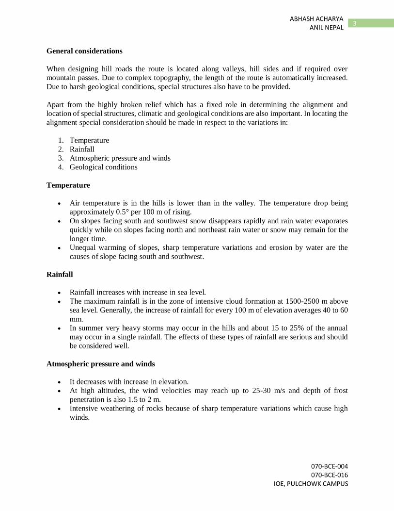
Geological conditions
The inclination of folds may vary from horizontal to vertical stratification of rock. These
folds often have faults. Limestone or sandstone folds may be interleaved with layers of
clay which when wetted may cause fracturing along their surface. This may result in shear
or slip fold.
The degree of stability of hill slopes depends on types of rock, degree of strata inclination
or dip, occurrence of clay seams, the hardness of the rocks and presence of ground water.
When locating the route
an engineer must study
the details of geological
conditions of that area and
follow stable hill slopes
where no ground water,
landslides, and unstable
folds occur.
Route location in Hills
Hill roads may follow
different path according
to the feasibility of the
road. However, a hill road
alignment varies for the
sections along the valley
bottom and along the
mountain pass. The first is
called river route and the
second is called ridge
route.
River route
The location of a route
along a river valley is the
most frequent case of hill
alignment as there is a
great advantage of
running a road at a gentle
gradient. Also, there is a
benefit of low
construction cost and
operation cost.
070-BCE-004 070-BCE-016
IOE, PULCHOWK CAMPUS
5 ABHASH ACHARYA
ANIL NEPAL
However, a river valley may run through numerous horizontal curves. Requirements for the
construction of large bridges over tributaries also may occur. It may also be necessary to construct
special retaining structures and protection walls on hill side for safe guarding the road against
avalanches.
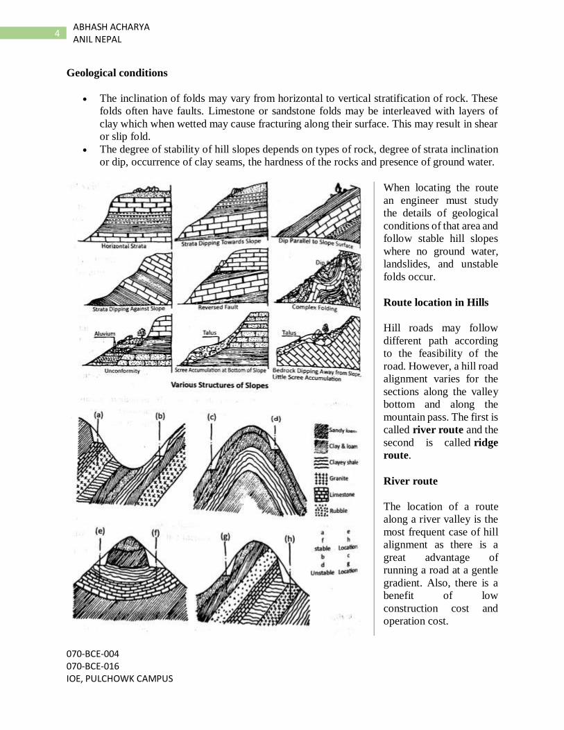
Some important considerations
Road bed should be
located sufficiently above
and away from the
maximum water level.
When the road bed is near
to the waste water course
embankment slope should
be well protected and
stabilized.
More care should be given
to geological and
hydrological structures.
Best alternatives should
be selected for crossing
water sources.
For example, as shown in figure a
road is to be connected from A to
B.
The first alternative runs through alluvial making a bridge. However, it may not be feasible unless
there are strong foundations which may increase construction cost greatly.
The second alternative is located above the alluvial fan through which the bridge length is greatly
reduced
Similarly, other options like route III or IV may also be chosen depending upon the economic
comparison.
070-BCE-004 070-BCE-016 IOE, PULCHOWK CAMPUS
6 ABHASH ACHARYA ANIL NEPAL
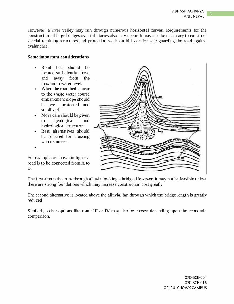
Ridge route
It is characterized by the very
steep gradient.
A large number of sharp
curves occurs on the road
with hair pin bends.
Extensive earthwork is
required.
The requirement for the
construction of special
structures.
The necessity of long length away from the air route.
Gradient
In hill roads, a heavy amount of earthwork is required. So to reduce the earthwork for reducing
construction cost the gradients selected are close to maximum. Although steep gradients help in
reducing earthwork and length of road, it also causes increased fuel consumption and reduction in
operating speed as the vehicles will be on low gears which will use more energy. So both these
factors must be taken into account and a suitable solution should be chosen.
The cumulative rise or fall in elevation should not exceed 100 m in mountainous terrain and 120
m in steep terrains. Vertical curves are designed as the square parabola. The curves should be
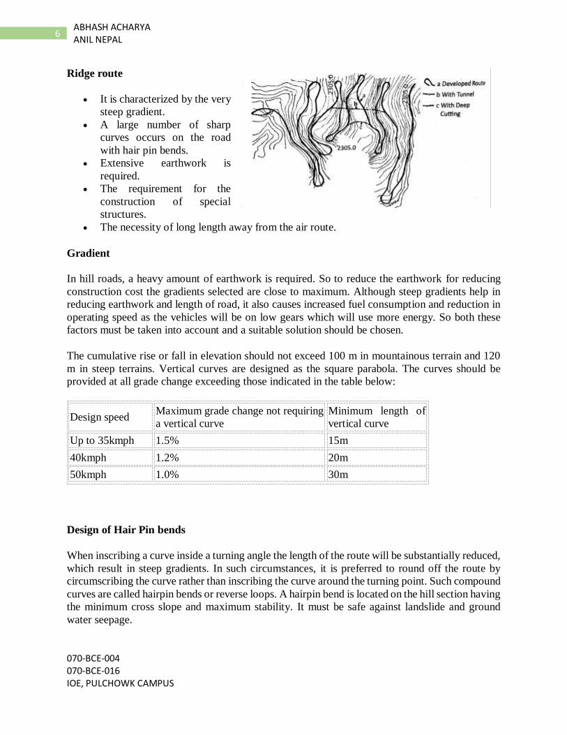
provided at all grade change exceeding those indicated in the table below:
Design speed Maximum grade change not requiring
a vertical curve
Minimum length of
vertical curve
Up to 35kmph 1.5% 15m
40kmph 1.2% 20m
50kmph 1.0% 30m
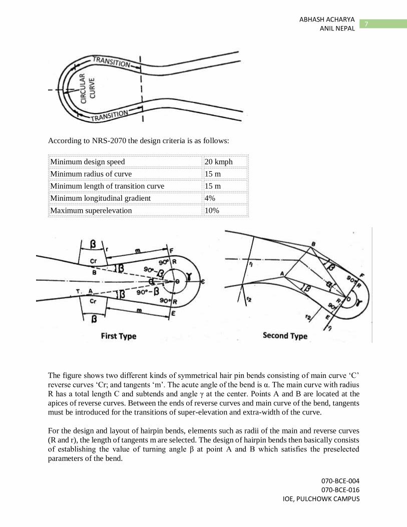
Design of Hair Pin bends
When inscribing a curve inside a turning angle the length of the route will be substantially reduced,
which result in steep gradients. In such circumstances, it is preferred to round off the route by
circumscribing the curve rather than inscribing the curve around the turning point. Such compound
curves are called hairpin bends or reverse loops. A hairpin bend is located on the hill section having
the minimum cross slope and maximum stability. It must be safe against landslide and ground
water seepage.
070-BCE-004 070-BCE-016
IOE, PULCHOWK CAMPUS
7 ABHASH ACHARYA
ANIL NEPAL
According to NRS-2070 the design criteria is as follows:
Minimum design speed 20 kmph
Minimum radius of curve 15 m
Minimum length of transition curve 15 m
Minimum longitudinal gradient 4%
Maximum superelevation 10%
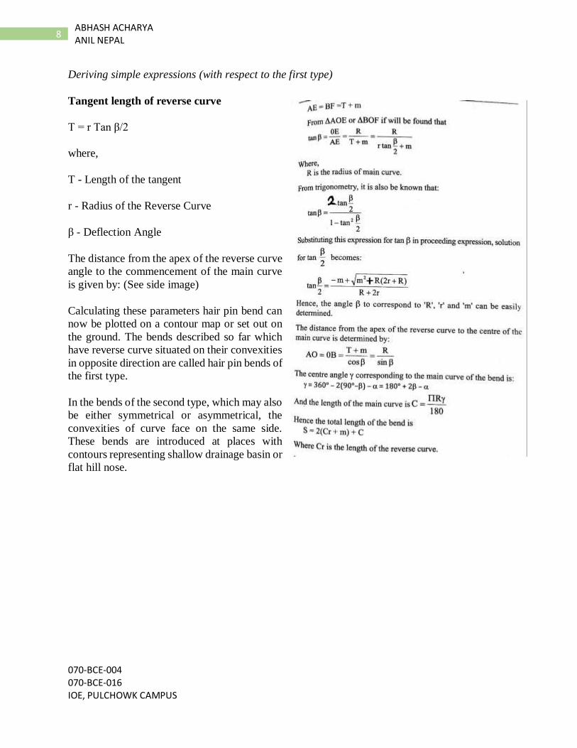
The figure shows two different kinds of symmetrical hair pin bends consisting of main curve ‘C’
reverse curves ‘Cr; and tangents ‘m’. The acute angle of the bend is α. The main curve with radius
R has a total length C and subtends and angle γ at the center. Points A and B are located at the
apices of reverse curves. Between the ends of reverse curves and main curve of the bend, tangents
must be introduced for the transitions of super-elevation and extra-width of the curve.
For the design and layout of hairpin bends, elements such as radii of the main and reverse curves
(R and r), the length of tangents m are selected. The design of hairpin bends then basically consists
of establishing the value of turning angle β at point A and B which satisfies the preselected
parameters of the bend.
070-BCE-004 070-BCE-016 IOE, PULCHOWK CAMPUS
8 ABHASH ACHARYA ANIL NEPAL
Deriving simple expressions (with respect to the first type)
Tangent length of reverse curve
T = r Tan β/2
where,
T - Length of the tangent
r - Radius of the Reverse Curve
β - Deflection Angle
The distance from the apex of the reverse curve
angle to the commencement of the main curve
is given by: (See side image)
Calculating these parameters hair pin bend can
now be plotted on a contour map or set out on
the ground. The bends described so far which
have reverse curve situated on their convexities
in opposite direction are called hair pin bends of
the first type.
In the bends of the second type, which may also
be either symmetrical or asymmetrical, the
convexities of curve face on the same side.
These bends are introduced at places with
contours representing shallow drainage basin or
flat hill nose.
070-BCE-004 070-BCE-016
IOE, PULCHOWK CAMPUS
9 ABHASH ACHARYA
ANIL NEPAL
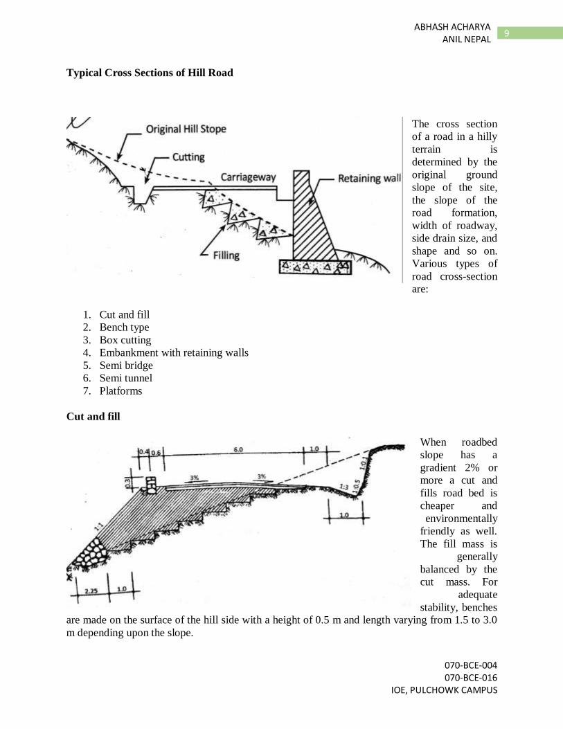
Typical Cross Sections of Hill Road
The cross section
of a road in a hilly
terrain is
determined by the
original ground
slope of the site,
the slope of the
road formation,
width of roadway,
side drain size, and
shape and so on.
Various types of
road cross-section
are:
1. Cut and fill
2. Bench type
3. Box cutting
4. Embankment with retaining walls
5. Semi bridge
6. Semi tunnel
7. Platforms
Cut and fill
When roadbed
slope has a
gradient 2% or
more a cut and
fills road bed is
cheaper and
environmentally
friendly as well.
The fill mass is
generally
balanced by the
cut mass. For
adequate
stability, benches
are made on the surface of the hill side with a height of 0.5 m and length varying from 1.5 to 3.0
m depending upon the slope.
070-BCE-004 070-BCE-016 IOE, PULCHOWK CAMPUS
10 ABHASH ACHARYA ANIL NEPAL
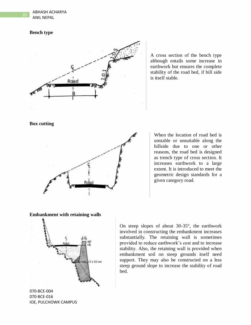
Bench type
A cross section of the bench type
although entails some increase in
earthwork but ensures the complete
stability of the road bed, if hill side
is itself stable.
Box cutting
When the location of road bed is
unstable or unsuitable along the
hillside due to one or other
reasons, the road bed is designed
as trench type of cross section. It
increases earthwork to a large
extent. It is introduced to meet the
geometric design standards for a
given category road.
Embankment with retaining walls
On steep slopes of about 30-35°, the earthwork
involved in constructing the embankment increases
substantially. The retaining wall is sometimes
provided to reduce earthwork’s cost and to increase
stability. Also, the retaining wall is provided when
embankment soil on steep grounds itself need
support. They may also be constructed on a less
steep ground slope to increase the stability of road
bed.
070-BCE-004 070-BCE-016
IOE, PULCHOWK CAMPUS
11 ABHASH ACHARYA
ANIL NEPAL
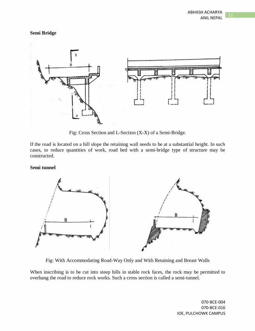
Semi Bridge
Fig: Cross Section and L-Section (X-X) of a Semi-Bridge.
If the road is located on a hill slope the retaining wall needs to be at a substantial height. In such
cases, to reduce quantities of work, road bed with a semi-bridge type of structure may be
constructed.
Semi tunnel
Fig: With Accommodating Road-Way Only and With Retaining and Breast Walls
When inscribing is to be cut into steep hills in stable rock faces, the rock may be permitted to
overhang the road to reduce rock works. Such a cross section is called a semi-tunnel.
070-BCE-004 070-BCE-016 IOE, PULCHOWK CAMPUS
12 ABHASH ACHARYA ANIL NEPAL
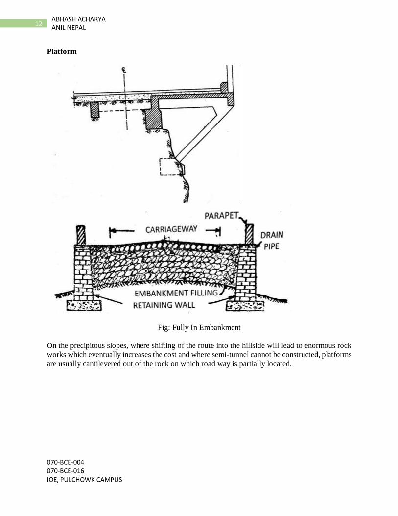
Platform
Fig: Fully In Embankment
On the precipitous slopes, where shifting of the route into the hillside will lead to enormous rock
works which eventually increases the cost and where semi-tunnel cannot be constructed, platforms
are usually cantilevered out of the rock on which road way is partially located.
070-BCE-004 070-BCE-016
IOE, PULCHOWK CAMPUS
13 ABHASH ACHARYA
ANIL NEPAL
5.3 Special Structures in Hill Roads
When constructing hill roads a lot of special structures are required owing to harsh geological and
hydrological conditions as well as highly broken relief.
The following types of structures are mostly used in the hill roads for strength durability and
stability:
1. Retaining structures
2. Drainage structures
3. Slope protection structures
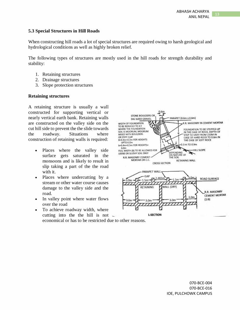
Retaining structures
A retaining structure is usually a wall
constructed for supporting vertical or
nearly vertical earth bank. Retaining walls
are constructed on the valley side on the
cut hill side to prevent the the slide towards
the roadway. Situations where
construction of retaining walls is required:
Places where the valley side
surface gets saturated in the
monsoons and is likely to result in
slip taking a part of the the road
with it.
Places where undercutting by a
stream or other water course causes
damage to the valley side and the
road.
In valley point where water flows
over the road
To achieve roadway width, where
cutting into the the hill is not
economical or has to be restricted due to other reasons.
070-BCE-004 070-BCE-016 IOE, PULCHOWK CAMPUS
14 ABHASH ACHARYA ANIL NEPAL
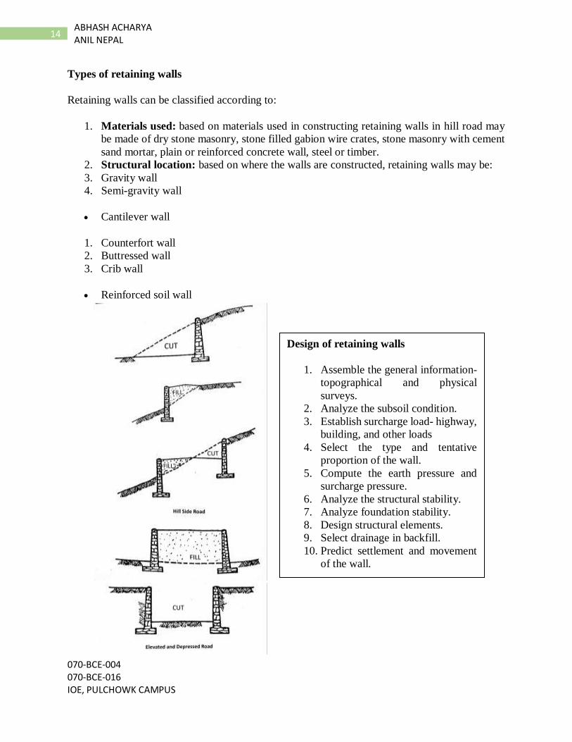
Types of retaining walls
Retaining walls can be classified according to:
1. Materials used: based on materials used in constructing retaining walls in hill road may
be made of dry stone masonry, stone filled gabion wire crates, stone masonry with cement
sand mortar, plain or reinforced concrete wall, steel or timber.
2. Structural location: based on where the walls are constructed, retaining walls may be:
3. Gravity wall
4. Semi-gravity wall
Cantilever wall
1. Counterfort wall
2. Buttressed wall
3. Crib wall
Reinforced soil wall
Design of retaining walls
1. Assemble the general information-
topographical and physical
surveys.
2. Analyze the subsoil condition.
3. Establish surcharge load- highway,
building, and other loads
4. Select the type and tentative
proportion of the wall.
5. Compute the earth pressure and
surcharge pressure.
6. Analyze the structural stability.
7. Analyze foundation stability.
8. Design structural elements.
9. Select drainage in backfill.
10. Predict settlement and movement
of the wall.
070-BCE-004 070-BCE-016
IOE, PULCHOWK CAMPUS
15 ABHASH ACHARYA
ANIL NEPAL
Drainage Structures
The main problems that hill roads face are the harmful effect of water. Water may come from
different sources to the parts of the road. This water must be drained using any means necessary.
Drainage of hill roads can be studied under following sub-topics:
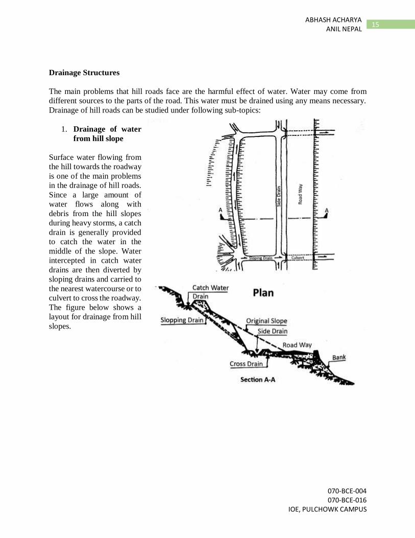
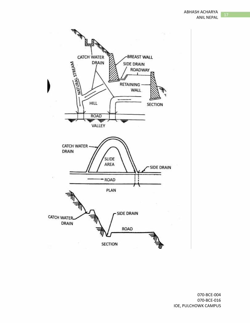
1. Drainage of water
from hill slope
Surface water flowing from
the hill towards the roadway
is one of the main problems
in the drainage of hill roads.
Since a large amount of
water flows along with
debris from the hill slopes
during heavy storms, a catch
drain is generally provided
to catch the water in the
middle of the slope. Water
intercepted in catch water
drains are then diverted by
sloping drains and carried to
the nearest watercourse or to
culvert to cross the roadway.
The figure below shows a
layout for drainage from hill
slopes.
070-BCE-004 070-BCE-016 IOE, PULCHOWK CAMPUS
16 ABHASH ACHARYA ANIL NEPAL
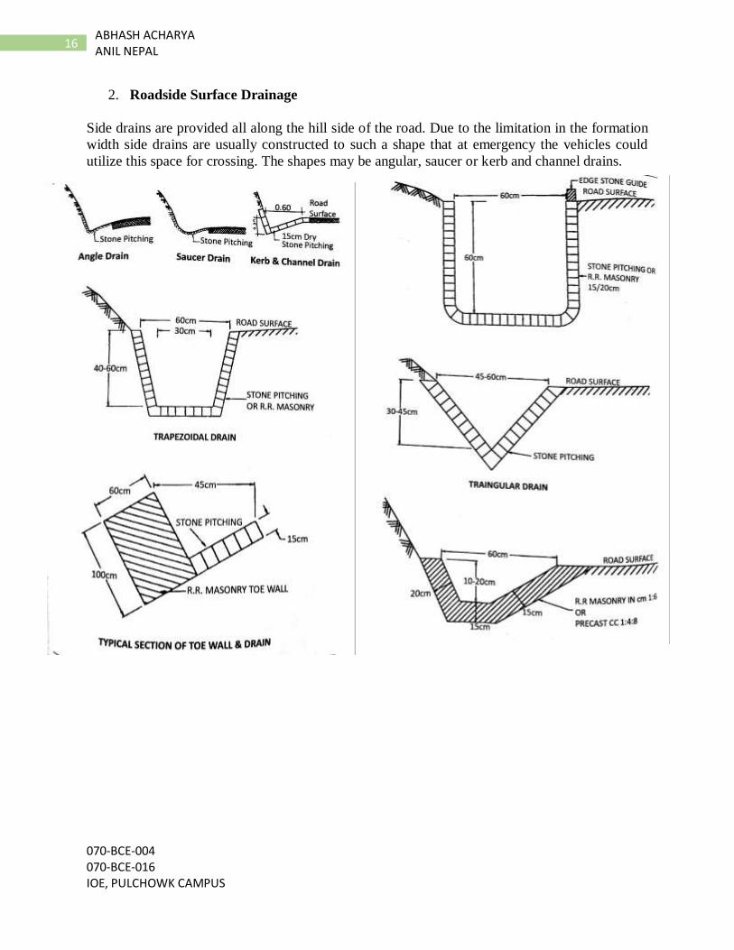
2. Roadside Surface Drainage
Side drains are provided all along the hill side of the road. Due to the limitation in the formation
width side drains are usually constructed to such a shape that at emergency the vehicles could
utilize this space for crossing. The shapes may be angular, saucer or kerb and channel drains.
070-BCE-004 070-BCE-016
IOE, PULCHOWK CAMPUS
17 ABHASH ACHARYA
ANIL NEPAL
070-BCE-004 070-BCE-016 IOE, PULCHOWK CAMPUS
18 ABHASH ACHARYA ANIL NEPAL
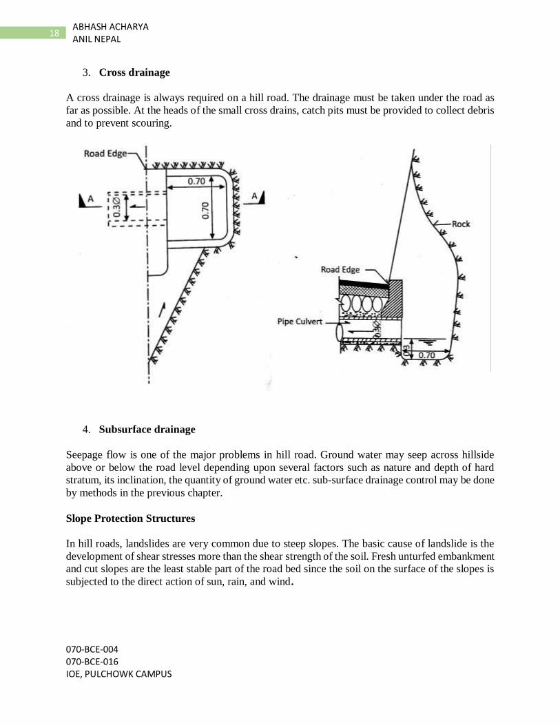
3. Cross drainage
A cross drainage is always required on a hill road. The drainage must be taken under the road as
far as possible. At the heads of the small cross drains, catch pits must be provided to collect debris
and to prevent scouring.
4. Subsurface drainage
Seepage flow is one of the major problems in hill road. Ground water may seep across hillside
above or below the road level depending upon several factors such as nature and depth of hard
stratum, its inclination, the quantity of ground water etc. sub-surface drainage control may be done
by methods in the previous chapter.
Slope Protection Structures
In hill roads, landslides are very common due to steep slopes. The basic cause of landslide is the
development of shear stresses more than the shear strength of the soil. Fresh unturfed embankment
and cut slopes are the least stable part of the road bed since the soil on the surface of the slopes is
subjected to the direct action of sun, rain, and wind.
070-BCE-004 070-BCE-016
IOE, PULCHOWK CAMPUS
19 ABHASH ACHARYA
ANIL NEPAL
Causes of landslides
Increase in moisture content of the soil in hill slopes which increases the pore water
pressure.
Alternate swelling and contracting of the soil mass.
Seepage pressure of percolating groundwater.
Steeper slopes.
Human activities like blasting and using heavy vehicles at unstable zones.
Preventive measures
The highway may be realigned at areas more prone to landslides.
Construction of retaining walls must be done at places where required
Adopting easy slopes during design and construction of the road.
Treatment of slopes to increase stability conditions.
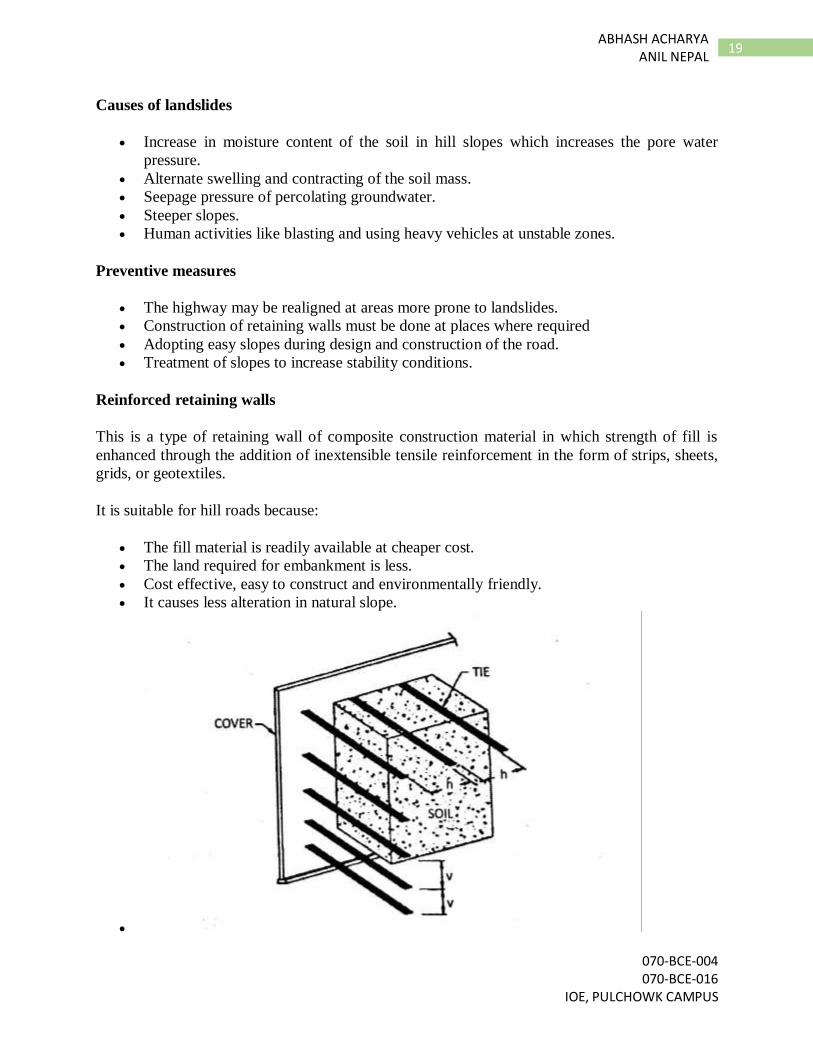
Reinforced retaining walls
This is a type of retaining wall of composite construction material in which strength of fill is
enhanced through the addition of inextensible tensile reinforcement in the form of strips, sheets,
grids, or geotextiles.
It is suitable for hill roads because:
The fill material is readily available at cheaper cost.
The land required for embankment is less.
Cost effective, easy to construct and environmentally friendly.
It causes less alteration in natural slope.
070-BCE-004 070-BCE-016 IOE, PULCHOWK CAMPUS
20 ABHASH ACHARYA ANIL NEPAL
River training structures
River training refers to the structural measures which are taken to improve a river and its banks.
River training is an important component in the prevention and mitigation of flash floods and
general flood control, as well as in other activities such as ensuring the safe passage of a flood
under a bridge. Hill roads along the river may also be in danger due to different problems created
by it.
Problems created by river
Frequent changes in river course.
Avulsion of one river into another.
Development of natural cut-off.
Landslides in catchment -rise in silt load.
Aggradation of river bed -high flood levels –Flooding
River instability -change in bed slopes (seismic activity).
Degradation of river bed downstream of a dam or a barrage.
Effects of flood embankment on the regime of rivers.
Effects of extraction of sand and boulders.
Effects of heavy urbanization along the river banks.
River training structures
River training structures can be classified into two main categories:
Transversal protection structures
Installed perpendicular to the water course:
Check dams, Spurs, Sills, Screen, bands, Porcupines, Bank protection as a bar.
Longitudinal protection structures.
Installed on river banks parallel to the river course:
Levees or earth fill embankments, Concrete embankments, Revetments and rock riprap, sheet
piles, etc
Other Protection Structures.
070-BCE-004 070-BCE-016
IOE, PULCHOWK CAMPUS
21 ABHASH ACHARYA
ANIL NEPAL
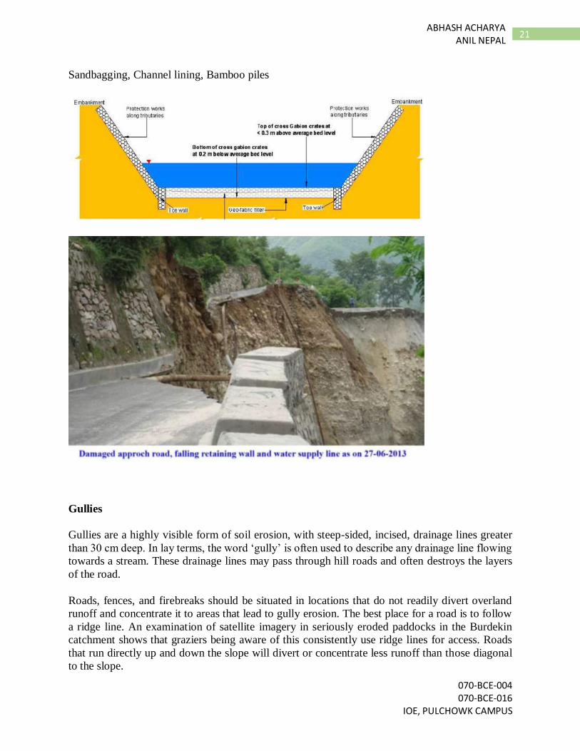
Sandbagging, Channel lining, Bamboo piles
Gullies
Gullies are a highly visible form of soil erosion, with steep-sided, incised, drainage lines greater
than 30 cm deep. In lay terms, the word ‘gully’ is often used to describe any drainage line flowing
towards a stream. These drainage lines may pass through hill roads and often destroys the layers
of the road.
Roads, fences, and firebreaks should be situated in locations that do not readily divert overland
runoff and concentrate it to areas that lead to gully erosion. The best place for a road is to follow
a ridge line. An examination of satellite imagery in seriously eroded paddocks in the Burdekin
catchment shows that graziers being aware of this consistently use ridge lines for access. Roads
that run directly up and down the slope will divert or concentrate less runoff than those diagonal
to the slope.
070-BCE-004 070-BCE-016 IOE, PULCHOWK CAMPUS
22 ABHASH ACHARYA ANIL NEPAL
Roads should have a profile that does not concentrate overland runoff. Roads that are below normal
ground level through constant use or inappropriate maintenance should be re-profiled to a form
that does not concentrate overland runoff; alternatively, they should have drainage works
incorporated to ensure runoff is dispersed onto stable areas. Associated table drains and mitre
drains should have a trapezoidal shape with a flat bottom and not a triangular shape that is more
conducive to eroding.
Gully control structures
Weir:
The durability of a weir depends on the construction materials used. Weirs can be made from wire
netting, rock, gabions, logs, tyres, concrete, steel sheet piles or hay bales. Strips of suitable
vegetation can also be used to act like a pervious weir. Where the vegetation has a relatively short
life, the intention is that the weirs will retain some sediment and promote vegetative growth before
the weir decays.
Types of weirs
Wire netting weirs
Hay bale weirs
Rock and gabion weirs
Tyre-rock weirs
Concrete and log weirs
Sand bag weirs
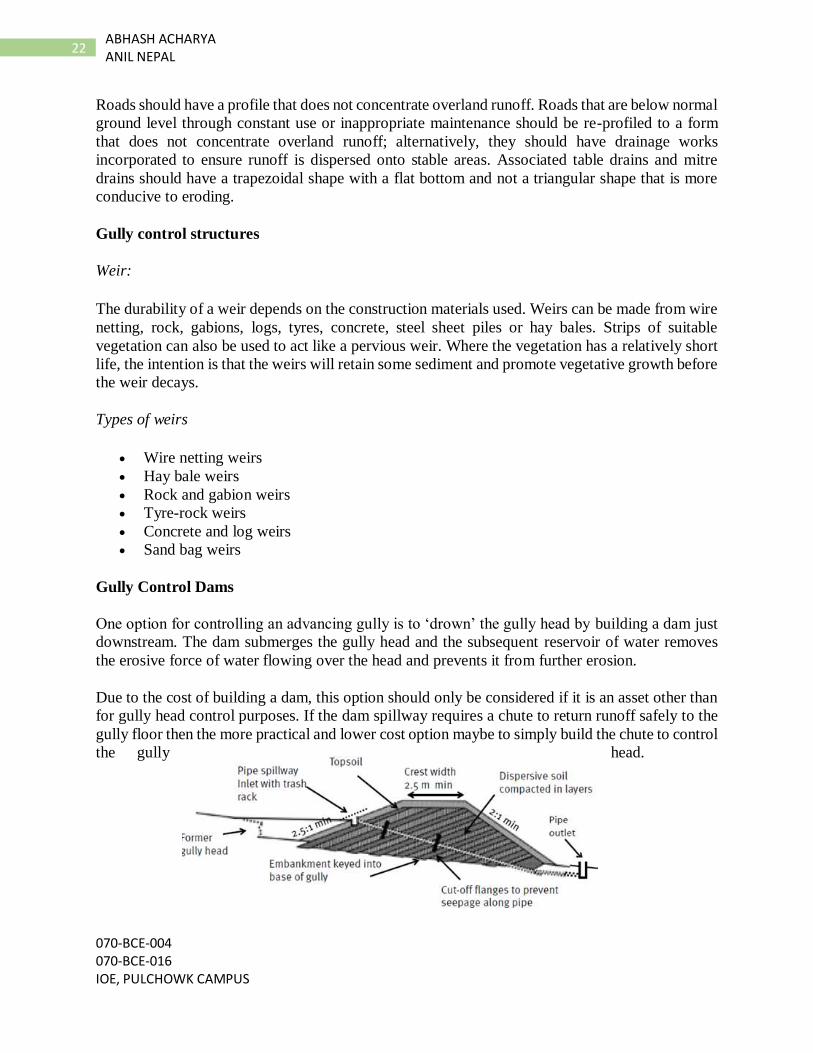
Gully Control Dams
One option for controlling an advancing gully is to ‘drown’ the gully head by building a dam just
downstream. The dam submerges the gully head and the subsequent reservoir of water removes
the erosive force of water flowing over the head and prevents it from further erosion.
Due to the cost of building a dam, this option should only be considered if it is an asset other than
for gully head control purposes. If the dam spillway requires a chute to return runoff safely to the
gully floor then the more practical and lower cost option maybe to simply build the chute to control
the gully head.
070-BCE-004 070-BCE-016
IOE, PULCHOWK CAMPUS
23 ABHASH ACHARYA
ANIL NEPAL
Chutes
Gully control chutes are formed by battering gully heads to an acceptable slope depending on the
method used to stabilize them. As well as for controlling gullies, chutes are used as by-washes in
farm dams. They are also used to convey water over steep road batters, to control bed erosion in
streams, and for urban developments such as sports fields.
Chutes require some form of energy dissipation at the outlet to help dissipate the energy gained
when runoff flows down the chute.
Chute failure often occurs when runoff fails to enter the chute properly. It is critical to control
potential leaks and flow bypassing, especially at the chute entrance, and also to ensure suitable
side walls contain the flows within the chute.
Bibliography:
Marsani A. and Shrestha D.K. (2071), Transportation Engineering Volume - I, Divine Print
Support, Lagan Tole, Kathmandu
Parajuli P.M. (1999), Course Manual of Transportation Engineering - I, IOE, Pulchowk Campus,
Lalitpur, Nepal.
Nepal Road Standard 2070
Nepal Rural Road Standard 2071


![laghu-udyog.gov.inlaghu-udyog.gov.in/.../circulars/annual_statement07hindi.pdfAuthor abhash [ ABHASH_737 ] Created Date 1/16/2008 11:27:00 AM](https://img.pdfslide.net/doc/110x75/608b87103fe84f4b42570838/laghu-udyoggovinlaghu-udyoggovincircularsannual-author-abhash-abhash737.jpg)

![Publication1 - Silent Hill · PDF file[SILENT HILL] rSlLENT HILL] fSlLENT HILL] fSlLENT HILL] îüä i Keiichiro Toyama Takayoshi Sato . añtöJD-E3 . HILL r. -54 -54 -350 -54 -34](https://img.pdfslide.net/doc/110x75/5aa23fe57f8b9aa0108cf926/publication1-silent-hill-silent-hill-rsllent-hill-fsllent-hill-fsllent-hill.jpg)