Embed Size (px)
Citation preview
ABLOY® DA460 SWING DOOR OPERATORInstallation and commissioning manual
2
APPROVALS / STANDARDS
73/23/EEC (Low Voltage directive)93/68/EEC (Low Voltage directive)89/336/EEC (EMC directive)Statement of fi re doors by Technical Research Centre of Finland
------------------ THIS MANUAL CONTAINS IMPORTANT SAFETY INSTRUCTIONS ------------------
Warning - IT IS IMPORTANT FOR SAFETY OF PERSONS TO FOLLOW THESE INSTRUCTIONS.
------------------------------------ SAVE THESE INSTRUCTIONS -----------------------------------------
This appliance is not intended for use by persons (including children) with reduced physical, sensory or mental capabilities, or lack of experience and knowledge, unless they have been given supervision or instruction concerning use of the appliance by a person responsible for their safety.
Do not allow children to play with fi xed controls.
Frequently examine the installation for imbalance and sings of wear or damage to cables, springs and mountings. Do not use if repair or adjustment is necessary.
Disconnect the supply when cleaning or other maintenance is being carried out.
Before installing the operator, check that the operator is in good mechanical condition and it opens and closes properly.
Ensure that entrapment between door and the surroundings is avoided.
Ensure that the operator is suited for installation. Check temperature, humidity, door weights, etc. restriction in line with specifi cations applicable in the manual or other Abloy® Oy material.
Note!Instructions, design specifi cations and illustrations which are contained in this manual are not binding. Abloy Oy reserves the right as part of ongoing product development to make changes without previous notice.
3
CONTENTS
Approvals ..... . . . . . . . . . . . . . . . . . . . . . . . . . . . . . . . . . . . . . . . . . . . . . . . . . . . . . . . . . . . . . . . . . . . . . . . . . . . . . . . . . . . . . . . . . . . . . . . . . . . . . . . . . . . . . . . . . . . . . . . 2Revision ..... . . . . . . . . . . . . . . . . . . . . . . . . . . . . . . . . . . . . . . . . . . . . . . . . . . . . . . . . . . . . . . . . . . . . . . . . . . . . . . . . . . . . . . . . . . . . . . . . . . . . . . . . . . . . . . . . . . . . . . . . . 4Content of delivery ..... . . . . . . . . . . . . . . . . . . . . . . . . . . . . . . . . . . . . . . . . . . . . . . . . . . . . . . . . . . . . . . . . . . . . . . . . . . . . . . . . . . . . . . . . . . . . . . . . . . . . . . . . 5General information ..... . . . . . . . . . . . . . . . . . . . . . . . . . . . . . . . . . . . . . . . . . . . . . . . . . . . . . . . . . . . . . . . . . . . . . . . . . . . . . . . . . . . . . . . . . . . . . . . . . . . . . . . 6Operation ..... . . . . . . . . . . . . . . . . . . . . . . . . . . . . . . . . . . . . . . . . . . . . . . . . . . . . . . . . . . . . . . . . . . . . . . . . . . . . . . . . . . . . . . . . . . . . . . . . . . . . . . . . . . . . . . . . . . . . . . 7Main switch and mode switch ..... . . . . . . . . . . . . . . . . . . . . . . . . . . . . . . . . . . . . . . . . . . . . . . . . . . . . . . . . . . . . . . . . . . . . . . . . . . . . . . . . . . . . . . . . . 7 Door weight ..... . . . . . . . . . . . . . . . . . . . . . . . . . . . . . . . . . . . . . . . . . . . . . . . . . . . . . . . . . . . . . . . . . . . . . . . . . . . . . . . . . . . . . . . . . . . . . . . . . . . . . . . . . . . . . . . . . . 8Installation ..... . . . . . . . . . . . . . . . . . . . . . . . . . . . . . . . . . . . . . . . . . . . . . . . . . . . . . . . . . . . . . . . . . . . . . . . . . . . . . . . . . . . . . . . . . . . . . . . . . . . . . . . . . . . . . . . . . . . . 9Internal connections ..... . . . . . . . . . . . . . . . . . . . . . . . . . . . . . . . . . . . . . . . . . . . . . . . . . . . . . . . . . . . . . . . . . . . . . . . . . . . . . . . . . . . . . . . . . . . . . . . . . . . . 14Commissioning ..... . . . . . . . . . . . . . . . . . . . . . . . . . . . . . . . . . . . . . . . . . . . . . . . . . . . . . . . . . . . . . . . . . . . . . . . . . . . . . . . . . . . . . . . . . . . . . . . . . . . . . . . . . . . . 15A safe door ..... . . . . . . . . . . . . . . . . . . . . . . . . . . . . . . . . . . . . . . . . . . . . . . . . . . . . . . . . . . . . . . . . . . . . . . . . . . . . . . . . . . . . . . . . . . . . . . . . . . . . . . . . . . . . . . . . . . 18External connections ..... . . . . . . . . . . . . . . . . . . . . . . . . . . . . . . . . . . . . . . . . . . . . . . . . . . . . . . . . . . . . . . . . . . . . . . . . . . . . . . . . . . . . . . . . . . . . . . . . . . . 19Connection examples ..... . . . . . . . . . . . . . . . . . . . . . . . . . . . . . . . . . . . . . . . . . . . . . . . . . . . . . . . . . . . . . . . . . . . . . . . . . . . . . . . . . . . . . . . . . . . . . . . . . . 21Self diagnostic ..... . . . . . . . . . . . . . . . . . . . . . . . . . . . . . . . . . . . . . . . . . . . . . . . . . . . . . . . . . . . . . . . . . . . . . . . . . . . . . . . . . . . . . . . . . . . . . . . . . . . . . . . . . . . . 27Maintenance ..... . . . . . . . . . . . . . . . . . . . . . . . . . . . . . . . . . . . . . . . . . . . . . . . . . . . . . . . . . . . . . . . . . . . . . . . . . . . . . . . . . . . . . . . . . . . . . . . . . . . . . . . . . . . . . . . . 28Spare parts ..... . . . . . . . . . . . . . . . . . . . . . . . . . . . . . . . . . . . . . . . . . . . . . . . . . . . . . . . . . . . . . . . . . . . . . . . . . . . . . . . . . . . . . . . . . . . . . . . . . . . . . . . . . . . . . . . . . . 29
4
REVISION
Following pages have been revised:
Page Revision
14 Safetysensor-unit added into connections.15-16 Settings updated.18 Added a note about safety sensors.19-26 All connections drawings updated.28 Safety sensor diagnistics added.29 Safetysensor-unit info added.
As at 22.05.2015.
5
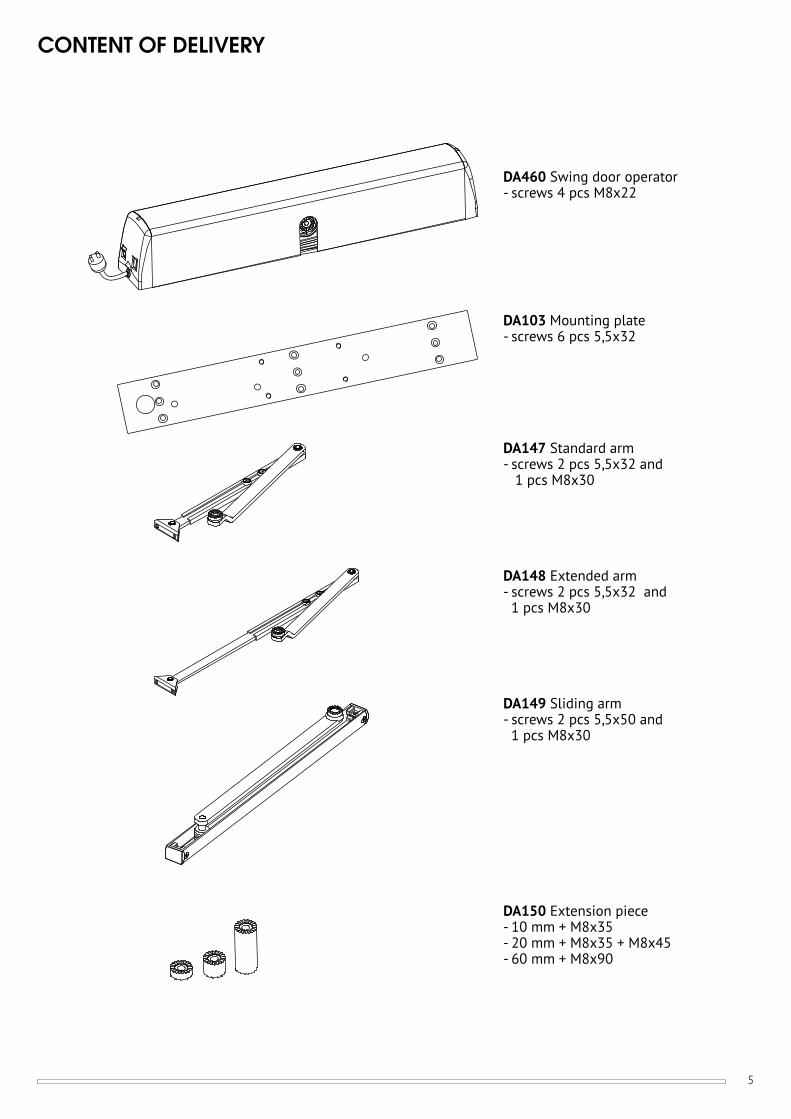
CONTENT OF DELIVERY
DA460 Swing door operator- screws 4 pcs M8x22
DA103 Mounting plate- screws 6 pcs 5,5x32
DA147 Standard arm- screws 2 pcs 5,5x32 and 1 pcs M8x30
DA148 Extended arm- screws 2 pcs 5,5x32 and 1 pcs M8x30
DA149 Sliding arm- screws 2 pcs 5,5x50 and 1 pcs M8x30
DA150 Extension piece - 10 mm + M8x35 - 20 mm + M8x35 + M8x45- 60 mm + M8x90
6
GENERAL INFORMATION
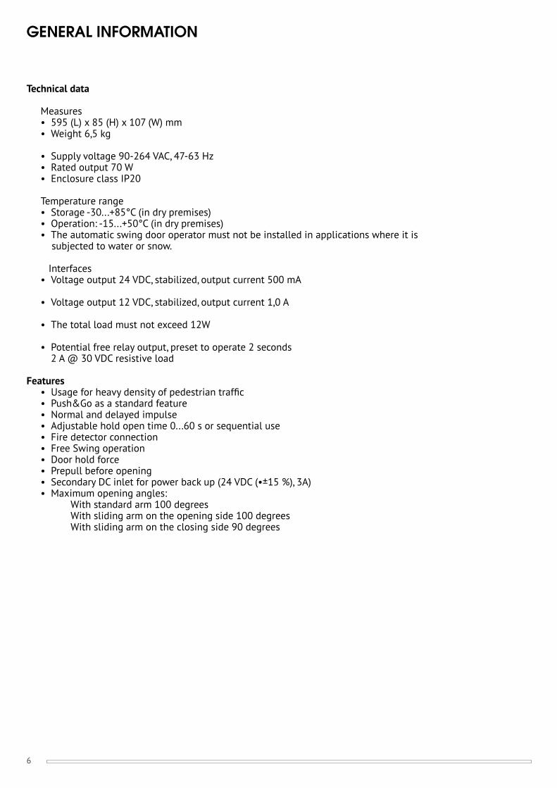
Technical data
Measures • 595 (L) x 85 (H) x 107 (W) mm • Weight 6,5 kg
• Supply voltage 90-264 VAC, 47-63 Hz • Rated output 70 W • Enclosure class IP20
Temperature range • Storage -30...+85°C (in dry premises) • Operation: -15...+50°C (in dry premises) • The automatic swing door operator must not be installed in applications where it is subjected to water or snow.
Interfaces • Voltage output 24 VDC, stabilized, output current 500 mA
• Voltage output 12 VDC, stabilized, output current 1,0 A
• The total load must not exceed 12W
• Potential free relay output, preset to operate 2 seconds 2 A @ 30 VDC resistive load
Features • Usage for heavy density of pedestrian traffi c • Push&Go as a standard feature • Normal and delayed impulse • Adjustable hold open time 0...60 s or sequential use • Fire detector connection • Free Swing operation • Door hold force • Prepull before opening • Secondary DC inlet for power back up (24 VDC (•±15 %), 3A) • Maximum opening angles: With standard arm 100 degrees With sliding arm on the opening side 100 degrees With sliding arm on the closing side 90 degrees
7
OPERATION
ABLOY® DA460 is an electromechanical swing door operator for heavy use. The door operator includes new free swing function: when using the door manually it operates lightly without motor’s resistance and the door can be left in open position when required. It can be used on both single and double, internal and external, fi re and emergency exit doors.
Safety features
Opening cycle: If the door is obstructed in opening cycle. The door is set free and hold open time is started. After 1 second, new trial is done to open the door. Maximum amount for trials is 4. If this is exceeded or hold open time is end, the door is closed.
Closing cycle: If the door is obstructed in closing cycle. The door is set free and 4 new trials are done to close the door. If the closing is still obstructed, the operator tries to close the door at one minute intervals.
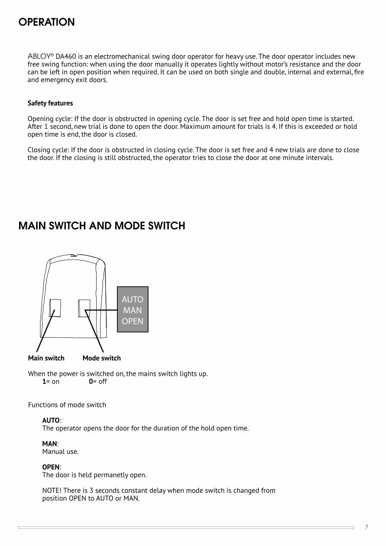
MAIN SWITCH AND MODE SWITCH
Main switch Mode switch
When the power is switched on, the mains switch lights up. 1= on 0= off
Functions of mode switch
AUTO: The operator opens the door for the duration of the hold open time.
MAN: Manual use.
OPEN: The door is held permanetly open.
NOTE! There is 3 seconds constant delay when mode switch is changed from position OPEN to AUTO or MAN.
8
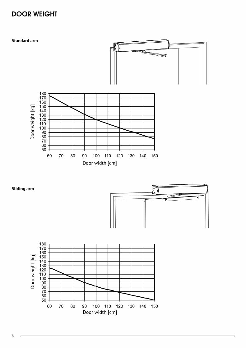
DOOR WEIGHT
5060708090
100110120130140150160170180
60 70 80 90 100 110 120 130 140 150
5060708090
100110120130140150160170180
60 70 80 90 100 110 120 130 140 150
Standard arm
Sliding arm
Doo
r wei
ght [
kg]
Door width [cm]
Doo
r wei
ght [
kg]
Door width [cm]
9
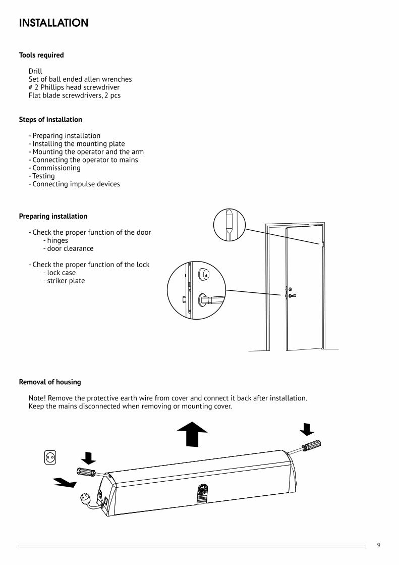
INSTALLATION
Tools required
DrillSet of ball ended allen wrenches# 2 Phillips head screwdriverFlat blade screwdrivers, 2 pcs
Steps of installation
- Preparing installation- Installing the mounting plate- Mounting the operator and the arm- Connecting the operator to mains- Commissioning- Testing- Connecting impulse devices
Preparing installation
- Check the proper function of the door - hinges - door clearance
- Check the proper function of the lock - lock case - striker plate
Removal of housing
Note! Remove the protective earth wire from cover and connect it back after installation.Keep the mains disconnected when removing or mounting cover.
10
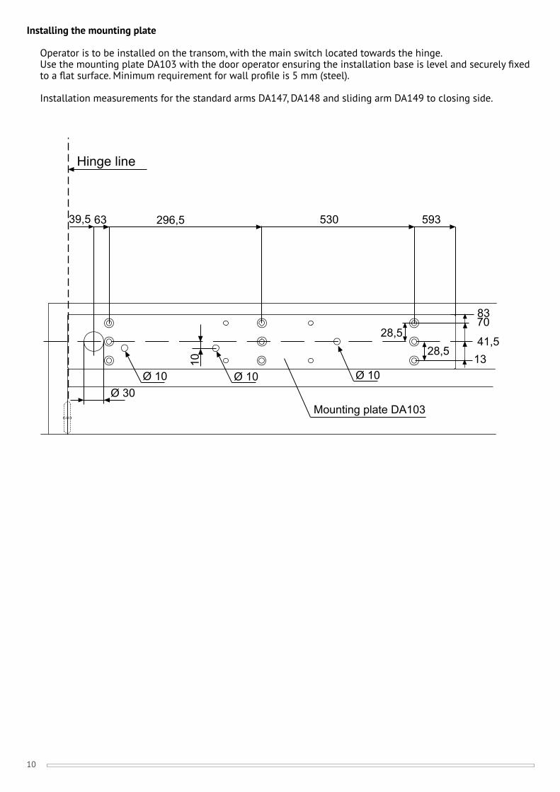
Installing the mounting plate
Operator is to be installed on the transom, with the main switch located towards the hinge. Use the mounting plate DA103 with the door operator ensuring the installation base is level and securely fi xed to a fl at surface. Minimum requirement for wall profi le is 5 mm (steel).
Installation measurements for the standard arms DA147, DA148 and sliding arm DA149 to closing side.
Hinge line
63 296,5 530 593
28,528,5
1341,5
7083
39,5
10
Ø 10Ø 10 Ø 10
Mounting plate DA103Ø 30
11
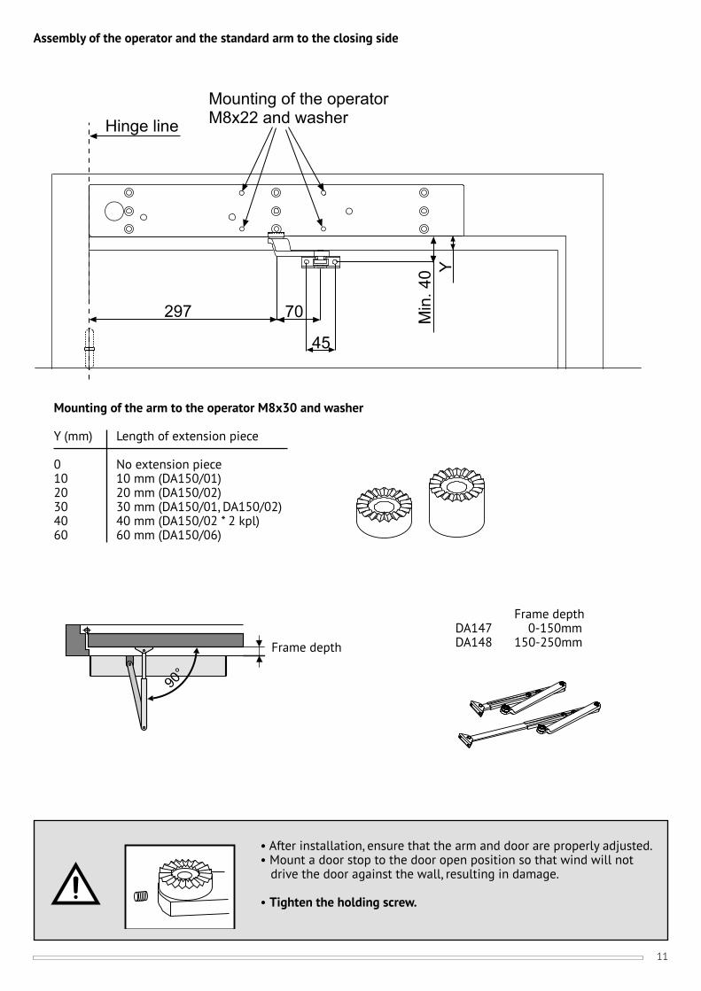
Assembly of the operator and the standard arm to the closing side
Hinge lineMounting of the operatorM8x22 and washer
70
45
Min
. 40
297
Y
90°
• After installation, ensure that the arm and door are properly adjusted.• Mount a door stop to the door open position so that wind will not drive the door against the wall, resulting in damage.
• Tighten the holding screw.
Mounting of the arm to the operator M8x30 and washer
Y (mm) Length of extension piece
0 No extension piece10 10 mm (DA150/01)20 20 mm (DA150/02)30 30 mm (DA150/01, DA150/02)40 40 mm (DA150/02 * 2 kpl)60 60 mm (DA150/06)
Frame depth
Frame depthDA147 0-150mmDA148 150-250mm
12
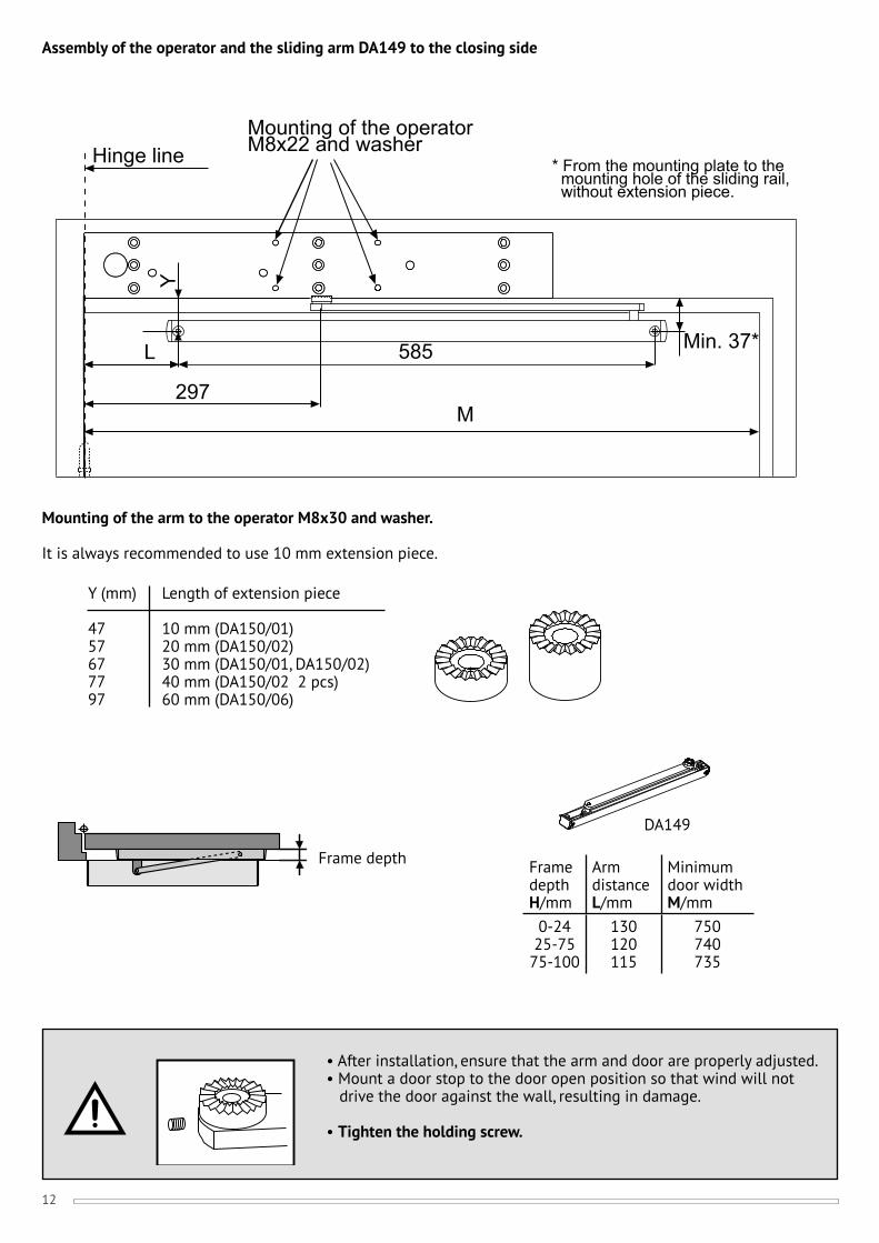
Assembly of the operator and the sliding arm DA149 to the closing side
• After installation, ensure that the arm and door are properly adjusted.• Mount a door stop to the door open position so that wind will not drive the door against the wall, resulting in damage.
• Tighten the holding screw.
Y
297
Min. 37*
M
L 585
Mounting of the operatorM8x22 and washerHinge line * From the mounting plate to the
mounting hole of the sliding rail, without extension piece.
Y (mm) Length of extension piece
47 10 mm (DA150/01)57 20 mm (DA150/02)67 30 mm (DA150/01, DA150/02)77 40 mm (DA150/02 2 pcs)97 60 mm (DA150/06)
Mounting of the arm to the operator M8x30 and washer.
It is always recommended to use 10 mm extension piece.
Frame depth
DA149
Frame depthH/mm
Arm distanceL/mm
Minimum door widthM/mm
0-2425-75
75-100
130120115
750740735
13
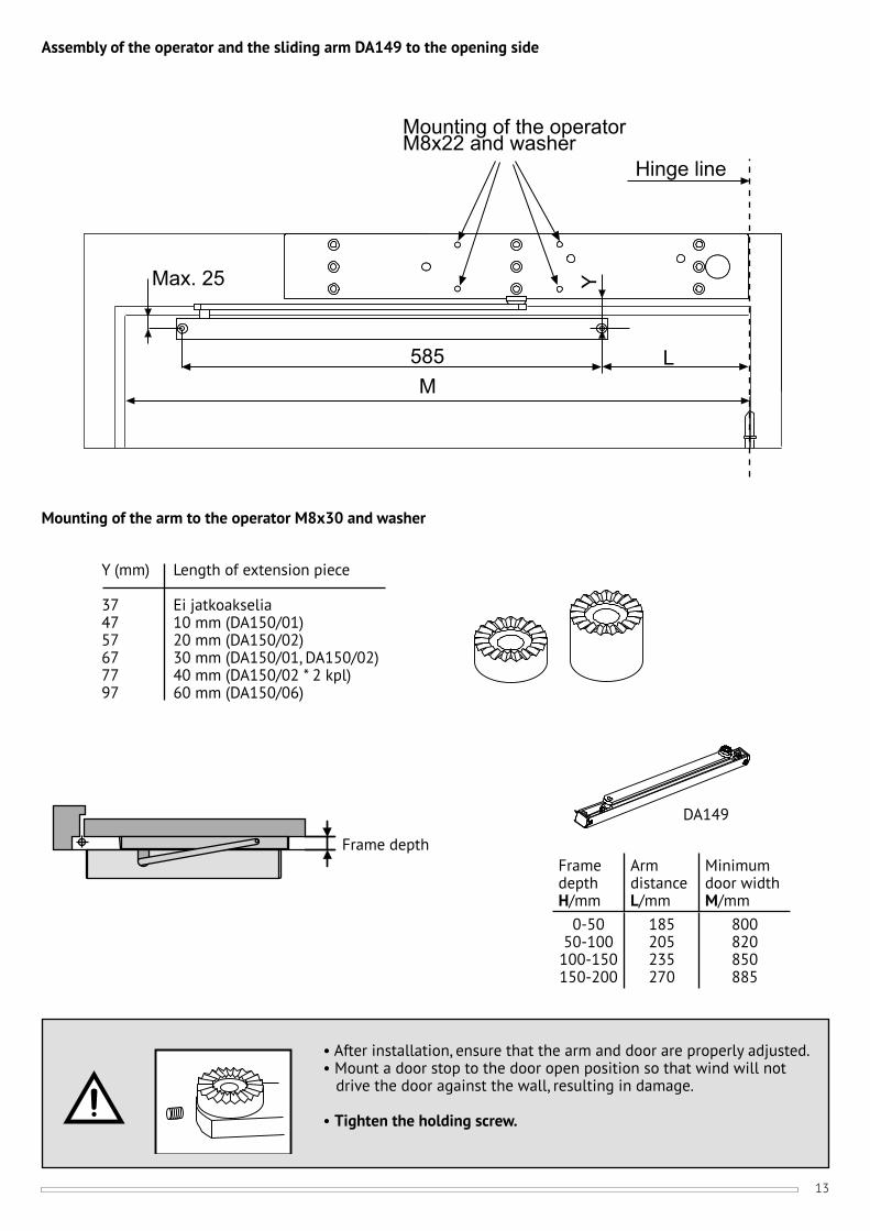
• After installation, ensure that the arm and door are properly adjusted.• Mount a door stop to the door open position so that wind will not drive the door against the wall, resulting in damage.
• Tighten the holding screw.
Assembly of the operator and the sliding arm DA149 to the opening side
Mounting of the operatorM8x22 and washer
Hinge line
585M
L
YMax. 25
Mounting of the arm to the operator M8x30 and washer
Y (mm) Length of extension piece
37 Ei jatkoakselia47 10 mm (DA150/01)57 20 mm (DA150/02)67 30 mm (DA150/01, DA150/02)77 40 mm (DA150/02 * 2 kpl)97 60 mm (DA150/06)
DA149
Frame depthFrame depthH/mm
Arm distanceL/mm
Minimum door widthM/mm
0-5050-100
100-150150-200
185205235270
800820850885

14
- Electrical connections should be made by a qualifi ed electrician.- The power plug must have an easy access.- If permanent connection is made unit must be equipped with an external switch providing all pole disconnection.- Keep the mains disconnected during installation.
INTERNAL CONNECTIONS
DC supply back-up
When not mains operated, or for back-up supply, the external 24 VDC (min. 3A) supply can be connected to X1 connectors 2 and 3. Connect + from DC supply back-up to X1 connector 2 and GND to X1 connector 3. No battery charging or maintenance is provided by DA460.
white
brown
white
brown
I
0
LN
To motorredblack
Asentoanturi
Main switch
AUTO: red & blackMAN: NCOPEN: blue & black
X4
X2
X6
0V
DCAC
PE
blackX1
+ 24V backup+ 24V in
X5
whi
te
brow
n
white
External power supply unit +24VDC, min 3A
redblackblue
AUTOMAN
OPENSafetysensor-unit
Mode switch
CU
15
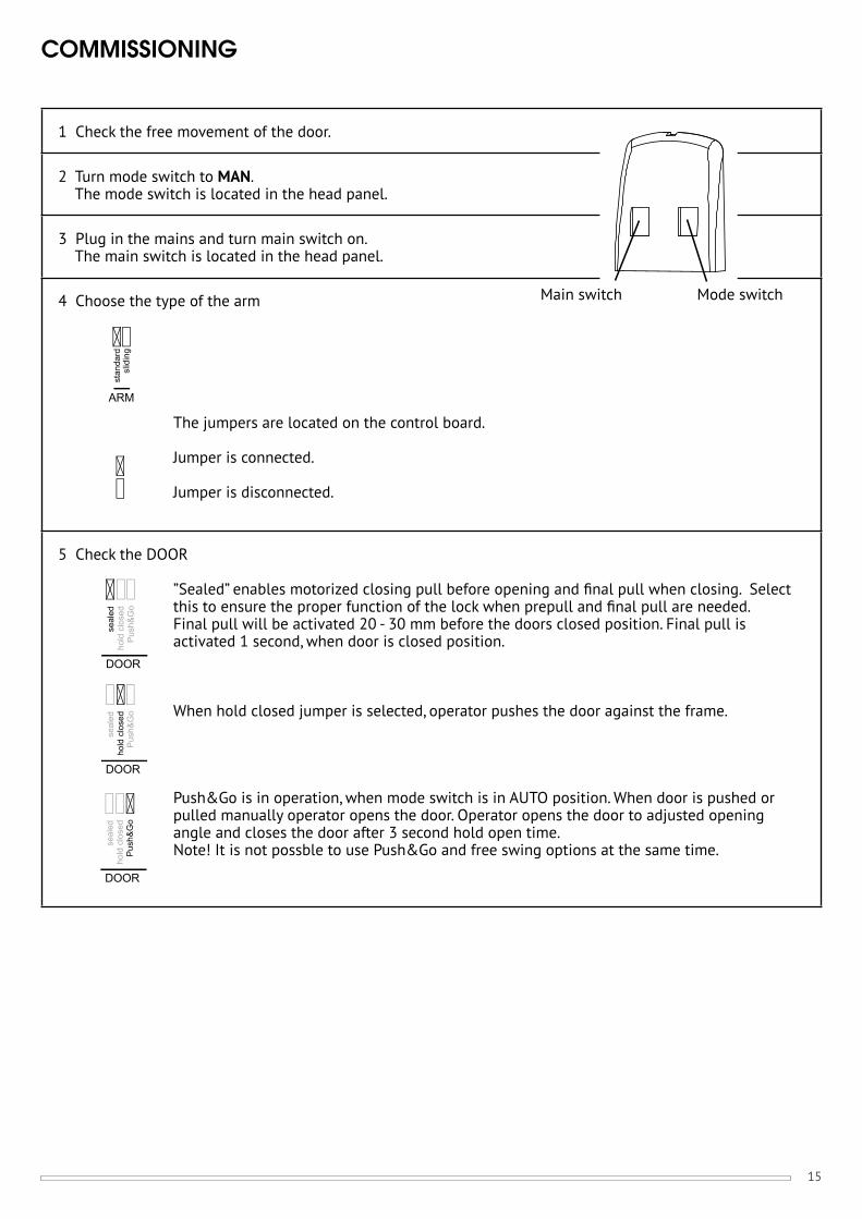
COMMISSIONING
1 Check the free movement of the door.
2 Turn mode switch to MAN. The mode switch is located in the head panel.
3 Plug in the mains and turn main switch on. The main switch is located in the head panel.
4 Choose the type of the arm
The jumpers are located on the control board.
Jumper is connected.
Jumper is disconnected.
5 Check the DOOR
”Sealed” enables motorized closing pull before opening and fi nal pull when closing. Select this to ensure the proper function of the lock when prepull and fi nal pull are needed. Final pull will be activated 20 - 30 mm before the doors closed position. Final pull is activated 1 second, when door is closed position.
When hold closed jumper is selected, operator pushes the door against the frame.
Push&Go is in operation, when mode switch is in AUTO position. When door is pushed or pulled manually operator opens the door. Operator opens the door to adjusted opening angle and closes the door after 3 second hold open time.Note! It is not possble to use Push&Go and free swing options at the same time.
ARM
stan
dard
slid
ing
seal
edho
ld c
lose
dP
ush&
Go
DOOR
seal
edho
ld c
lose
dP
ush&
Go
DOOR
seal
edho
ld c
lose
dP
ush&
Go
DOOR
Main switch Mode switch
16
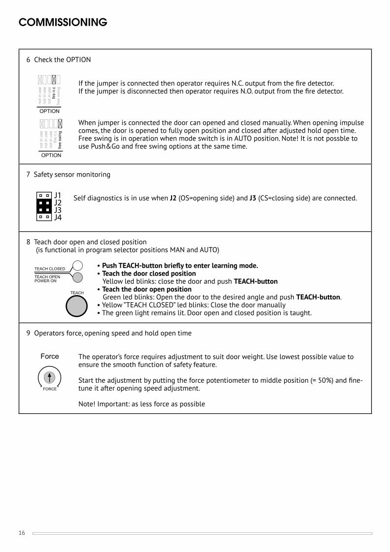
COMMISSIONING
6 Check the OPTION
If the jumper is connected then operator requires N.C. output from the fi re detector.If the jumper is disconnected then operator requires N.O. output from the fi re detector.
When jumper is connected the door can opened and closed manually. When opening impulse comes, the door is opened to fully open position and closed after adjusted hold open time.Free swing is in operation when mode switch is in AUTO position. Note! It is not possble to use Push&Go and free swing options at the same time.
7 Safety sensor monitoring
Self diagnostics is in use when J2 (OS=opening side) and J3 (CS=closing side) are connected.
8 Teach door open and closed position (is functional in program selector positions MAN and AUTO)
• Push TEACH-button briefl y to enter learning mode.• Teach the door closed position Yellow led blinks: close the door and push TEACH-button• Teach the door open position Green led blinks: Open the door to the desired angle and push TEACH-button.• Yellow ”TEACH CLOSED” led blinks: Close the door manually• The green light remains lit. Door open and closed position is taught.
9 Operators force, opening speed and hold open time
The operator’s force requires adjustment to suit door weight. Use lowest possible value to ensure the smooth function of safety feature.
Start the adjustment by putting the force potentiometer to middle position (= 50%) and fi ne-tune it after opening speed adjustment.
Note! Important: as less force as possible
OPTION
OPTION
not i
n us
eno
t in
use
not i
n us
efir
e n.
cfre
e sw
ing
not i
n us
eno
t in
use
not i
n us
efir
e n.
cfre
e sw
ing
TEACH OPENPOWER ON
TEACH CLOSED
TEACH
FORCE
Force
J1J2J3J4

17
COMMISSIONING
Adjust the opening speed.
Minimum safe opening and closing times for door of various widths and weights are summarized in the table.
Hold open times
Adjust fi rst hold open time for delayed impulse and then hold open time for normal impulse. Adjusting the hold open time for delayed impulse
Entering the mode:• Turn mode switch to AUTO position.• Press TEACH button at least 3 seconds.• In the programming mode green led is lit, yellow led is fl ashing 3 times, pause, 3 times, pause...• Adjust the hold open time for delayed impulse (0...60 sec). Time starts when the door is in open position. Full right position (seq) of the potentiometer means that every other impulse either opens or closes the door.
Back to normal mode:• Press TEACH button at least 3 seconds or wait 2 minutes.• Turn mode switch to MAN position.
Adjusting hold open time for normal impulse
Adjust the hold open time (0...60 s). Time starts when the door is in open position. Full right position (seq) of the potentiometer means that every other impulse either opens or closes the door.
Note! For safe operation, always use low force, speed and long hold open time.
10 Test the operation
• Turn mode switch to AUTO.• Test the operation• If the function is not desired, repeat steps 4 to 9.
Resetting operator to factory settings (operator is moved to new door)
• Turn mode switch to OPEN.• Push TEACH-button briefl y. After that push TEACH-button 5 sec. Door open and closed position information is removed from the memory.
SPEEDmin max
HOLDOPEN
seq
0
60
HOLDOPEN
seq
0
60
Time (sec.) Door weight (kg)60 80 100 120
Door width(mm)
800100012001300
2,7 3,2 3,5 3,93,4 4,0 4,4 4,84,1 4,7 5,3 5,84,5 5,1 5,8 6,3

18
A SAFE DOOR
The safety of the door operator is controlled by basic adjustments; operator force, speeds, and hold open times.
• The operator force is an important adjustment. A high value affects to the safety feature and also to its sensitivity.• High speeds increases the energy transferred in the door causing it not stop correctly.• With hold open times the distance from impulse device to door is preset.
1. Adjust low speeds.2. Adjust the operator force to a low setting ensuring the safety feature activates on door moving.3. Adjust the hold open times.
By following these basic procedures the operator is safe in operation.
Note!!! High speeds and safety is only possible by fi tting of Safety sensors.
REMEMBER!With using safety sensors to opening and closings sides and activating self diagnostics, the door environment will be safe and meets the EN 16005-standards.
Note. fi ll the included EN 16005 checklist.
19
EXTERNAL CONNECTIONS
12
34
56
78
910
1112
+24V out
GND
Normal
Not
y
Lockin
g
GND
circuit
t
in use
r
impulse
Fire
detector
+12V out
Delayed
impulse
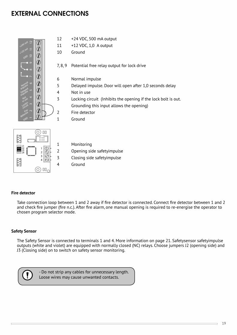
12 +24 VDC, 500 mA output11 +12 VDC, 1,0 A output10 Ground
7, 8, 9 Potential free relay output for lock drive
6 Normal impulse5 Delayed impulse. Door will open after 1,0 seconds delay4 Not in use3 Locking circuit (Inhibits the opening if the lock bolt is out. Grounding this input allows the opening)2 Fire detector1 Ground
Fire detector
Take connection loop between 1 and 2 away if fi re detector is connected. Connect fi re detector between 1 and 2 and check fi re jumper (fi re n.c.). After fi re alarm, one manual opening is required to re-energise the operator to chosen program selector mode.
Safety Sensor
The Safety Sensor is connected to terminals 1 and 4. More information on page 21. Safetysensor safetyimpulse outputs (white and violet) are equipped with normally closed (NC) relays. Choose jumpers J2 (opening side) and J3 (Closing side) on to switch on safety sensor monitoring.
1234
J1J2J3J4
1 Monitoring2 Opening side safetyimpulse3 Closing side safetyimpulse4 Ground
- Do not strip any cables for unnecessary length. Loose wires may cause unwanted contacts.
20
EXTERNAL CONNECTIONS
Impulse inputs
The closing contact drive (NO) must be potential free. The impulse device, like a push button or motion sensor, must be installed within direct sight of the door. Maximum length of the impulse device cable is 30 meters. The total resistance of the control switch and its wiring must not exceed 100 ohm, when switch is closed.
Delayed impulse: delay = 1,0 seconds. When the operator receives the opening impulse, the lock is released immediately and door is opened after 1,0 seconds.
Normal impulse: Door is opened immediately.
- Do not strip any cables for unnecessary length. Loose wires may cause unwanted contacts.
21
CONNECTION EXAMPLES
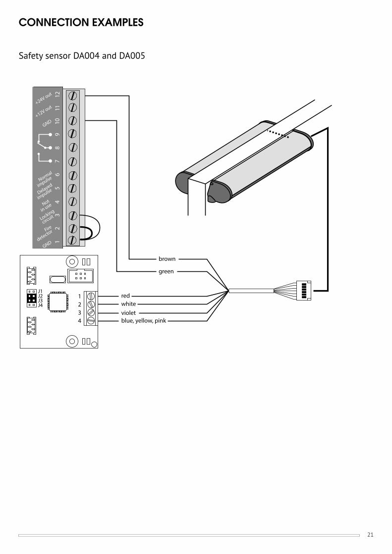
Safety sensor DA004 and DA005
redwhitevioletblue, yellow, pink
green
brown
12
34
56
78
910
1112
+24V out
GND
Normal
Not
y
Locking
GND
circuitin use
r
impulse
Fire
detector
+12V out
Delayed
impulse
1234
J1J2J3J4
22
CONNECTION EXAMPLES
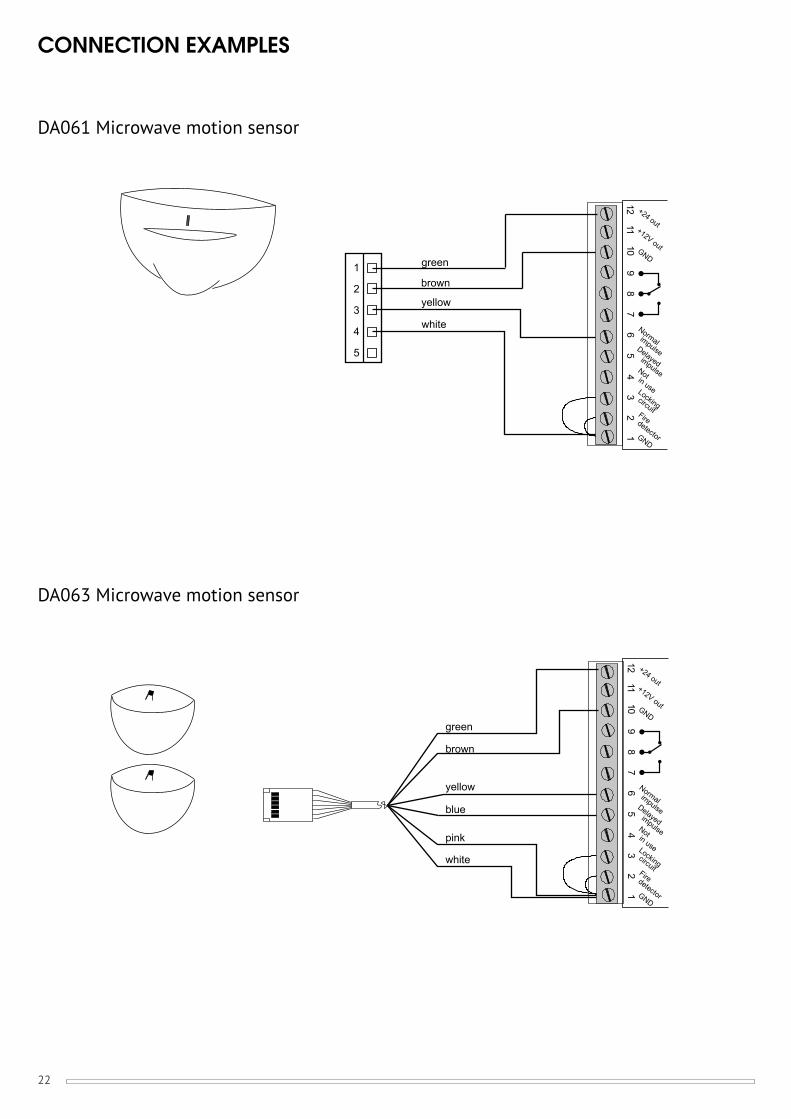
DA061 Microwave motion sensor
DA063 Microwave motion sensor
12
34
56
78
910
1112 +24 out
Normal
Not
Locking
GND
circuit
in use
impulse
Firedetector
+12V out
Delayedimpulse
GND
1
2
3
4
5
yellow
white
brown
green
12
34
56
78
910
1112 +24 out
Normal
Not
Locking
GND
circuit
in use
impulse
Firedetector
+12V out
Delayedimpulse
GND
yellow
white
green
pink
blue
brown
23
12
34
56
78
910
1112 +24 out
Normal
Not
Locking
GND
circuit
in use
impulse
Firedetector
+12V out
Delayedimpulse
GND
CO
MN
.ON
.C
red
black
blue
X2
X5
13
2
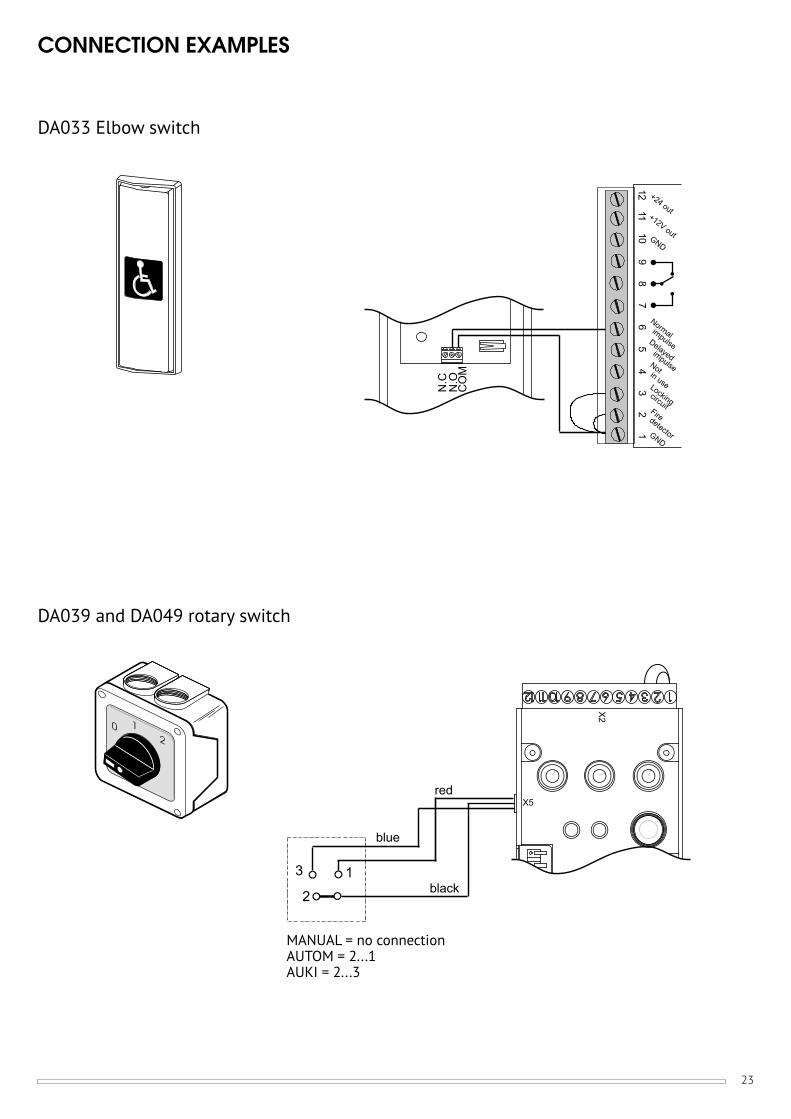
CONNECTION EXAMPLES
DA033 Elbow switch
DA039 and DA049 rotary switch
MANUAL = no connectionAUTOM = 2...1AUKI = 2...3
24
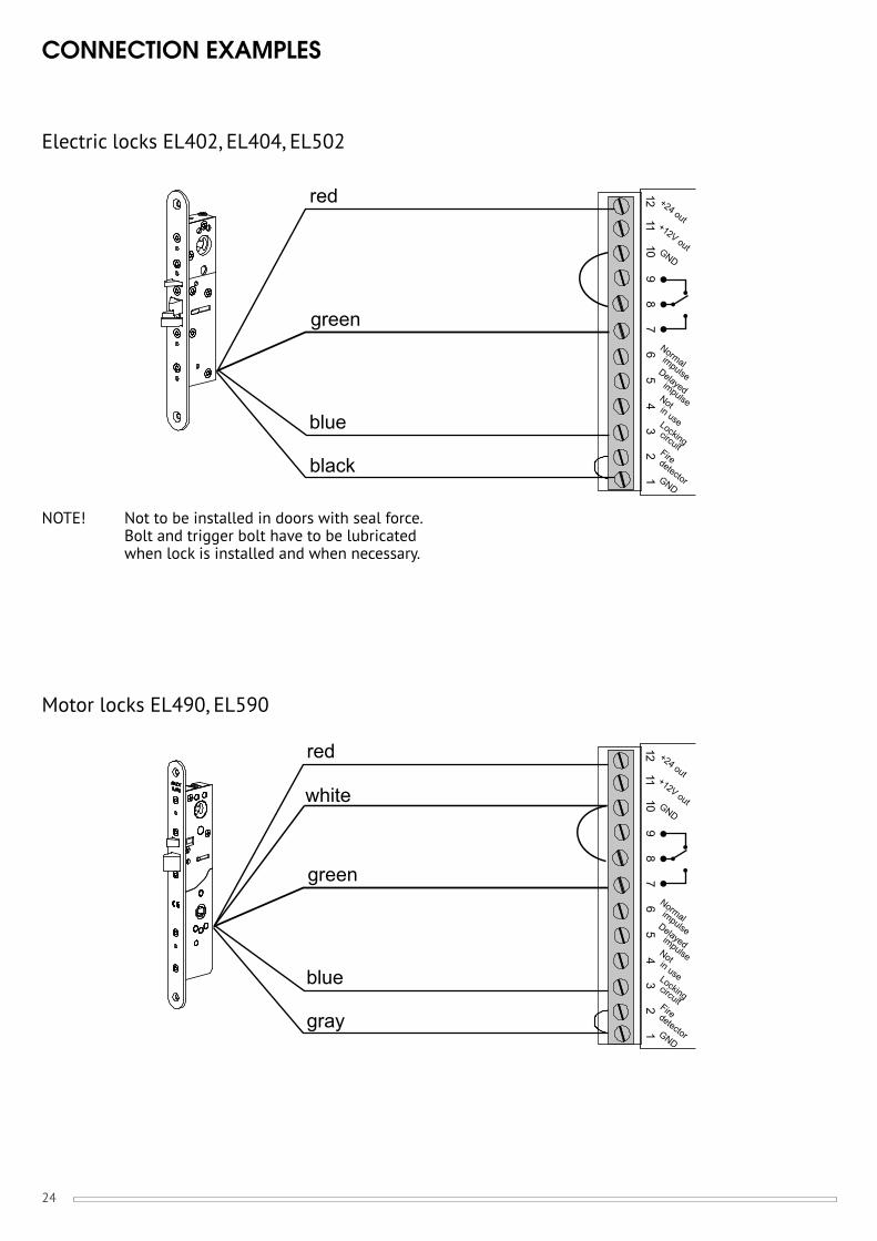
CONNECTION EXAMPLES
Electric locks EL402, EL404, EL502
Motor locks EL490, EL590
12
34
56
78
910
1112 +24 out
Normal
Not
Locking
GND
circuit
in use
impulse
Firedetector
+12V out
Delayedimpulse
GND
gray
blue
red
green
white
black
blue
red
green
12
34
56
78
910
1112 +24 out
Normal
Not
Locking
GND
circuit
in use
impulse
Firedetector
+12V out
Delayedimpulse
GND
NOTE! Not to be installed in doors with seal force. Bolt and trigger bolt have to be lubricated when lock is installed and when necessary.
25
12
34
56
78
910
1112 +24 out
Normal
Not
Locking
GND
circuit
in use
impulse
Firedetector
+12V out
Delayedimpulse
GND
12
34
56
78
910
1112 +24 out
Normal
Not
Locking
GND
circuit
in use
impulse
Firedetector
+12V out
Delayedimpulse
GND
Impulse device
ACTIVE DOOR
PASSIVE DOOR
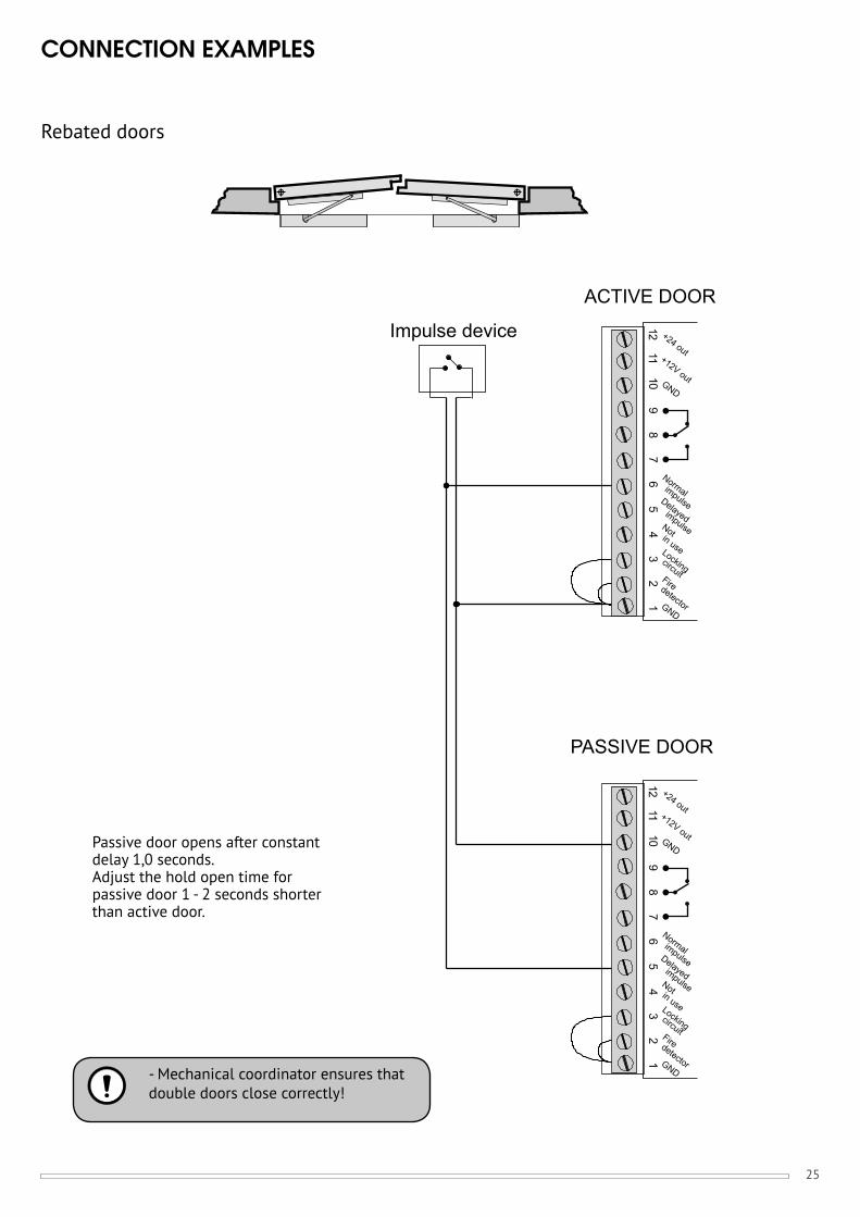
CONNECTION EXAMPLES
Rebated doors
Passive door opens after constant delay 1,0 seconds.Adjust the hold open time for passive door 1 - 2 seconds shorter than active door.
- Mechanical coordinator ensures that double doors close correctly!
26
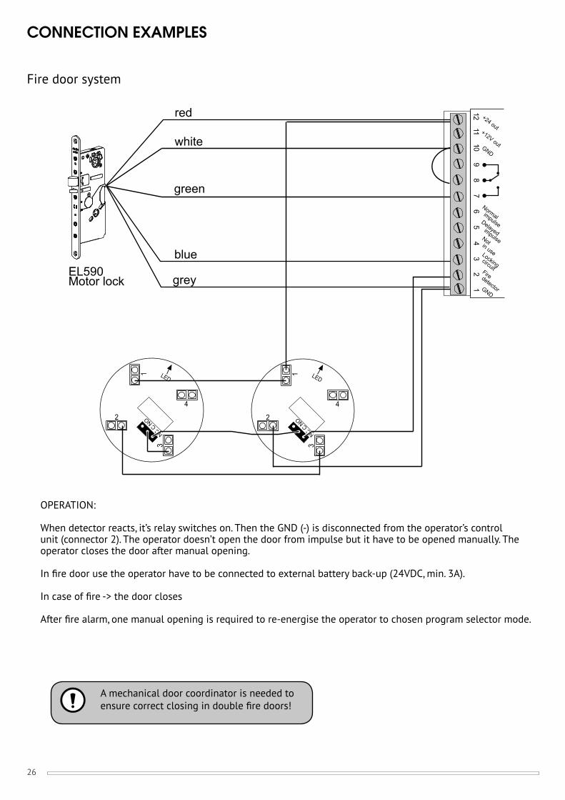
CONNECTION EXAMPLES
Fire door system
OPERATION:
When detector reacts, it’s relay switches on. Then the GND (-) is disconnected from the operator’s control unit (connector 2). The operator doesn’t open the door from impulse but it have to be opened manually. The operator closes the door after manual opening.
In fi re door use the operator have to be connected to external battery back-up (24VDC, min. 3A).
In case of fi re -> the door closes
After fi re alarm, one manual opening is required to re-energise the operator to chosen program selector mode.
12
34
56
78
910
1112 +24 out
Normal
Not
Locking
GND
circuit
in use
impulse
Firedetector
+12V out
Delayedimpulse
GND
4
3
2
1 LED
NC NO
C
4
3
2
1 LED
NC NO
C
grey
blue
red
green
white
EL590Motor lock
A mechanical door coordinator is needed to ensure correct closing in double fi re doors!
27
SELF DIAGNOSTICS (CONTROL UNIT)
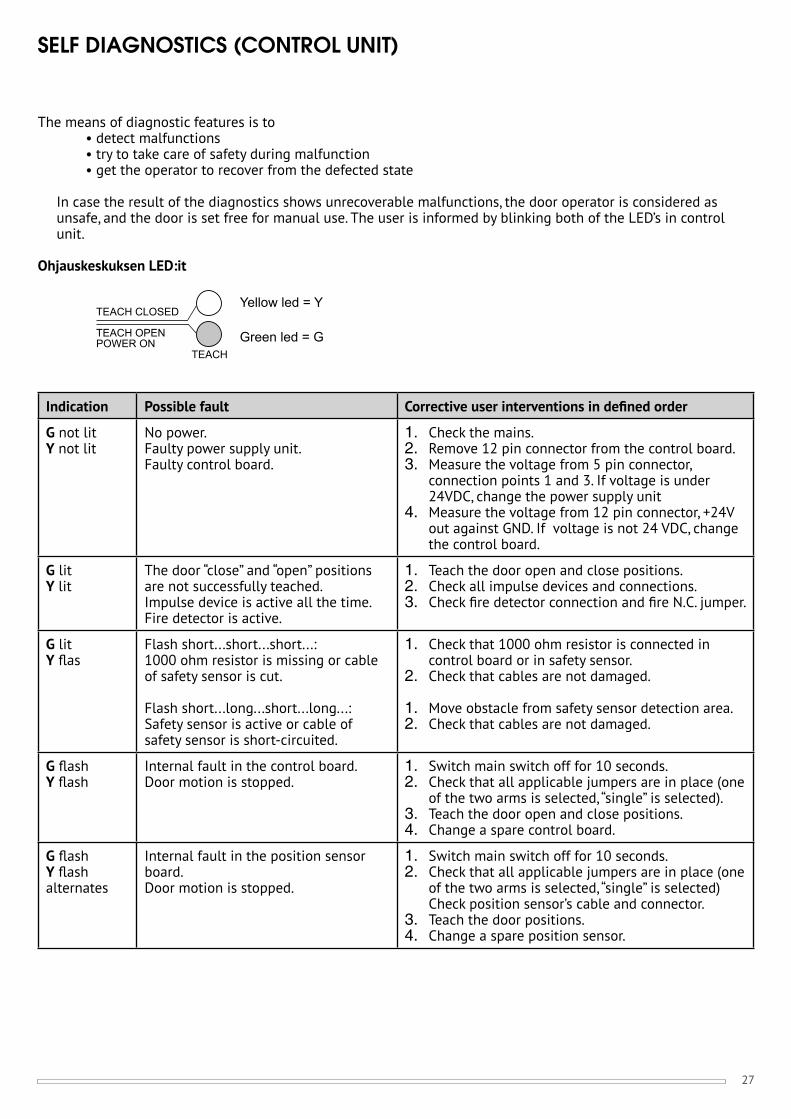
The means of diagnostic features is to • detect malfunctions • try to take care of safety during malfunction • get the operator to recover from the defected state
In case the result of the diagnostics shows unrecoverable malfunctions, the door operator is considered as unsafe, and the door is set free for manual use. The user is informed by blinking both of the LED’s in control unit.
Ohjauskeskuksen LED:it
Indication Possible fault Corrective user interventions in defi ned order
G not lit Y not lit
No power.Faulty power supply unit.Faulty control board.
1. Check the mains.2. Remove 12 pin connector from the control board.3. Measure the voltage from 5 pin connector,
connection points 1 and 3. If voltage is under 24VDC, change the power supply unit
4. Measure the voltage from 12 pin connector, +24V out against GND. If voltage is not 24 VDC, change the control board.
G litY lit
The door “close” and “open” positions are not successfully teached.Impulse device is active all the time.Fire detector is active.
1. Teach the door open and close positions.2. Check all impulse devices and connections.3. Check fi re detector connection and fi re N.C. jumper.
G litY fl as
Flash short...short...short...:1000 ohm resistor is missing or cable of safety sensor is cut.
Flash short...long...short...long...:Safety sensor is active or cable of safety sensor is short-circuited.
1. Check that 1000 ohm resistor is connected in control board or in safety sensor.
2. Check that cables are not damaged.
1. Move obstacle from safety sensor detection area.2. Check that cables are not damaged.
G fl ashY fl ash
Internal fault in the control board. Door motion is stopped.
1. Switch main switch off for 10 seconds.2. Check that all applicable jumpers are in place (one
of the two arms is selected, “single” is selected).3. Teach the door open and close positions.4. Change a spare control board.
G fl ashY fl ash alternates
Internal fault in the position sensor board. Door motion is stopped.
1. Switch main switch off for 10 seconds.2. Check that all applicable jumpers are in place (one
of the two arms is selected, “single” is selected) Check position sensor’s cable and connector.
3. Teach the door positions.4. Change a spare position sensor.
TEACH OPENPOWER ON
TEACH CLOSED
TEACH
Yellow led = Y
Green led = G
28
MAINTENANCE
Requirements for trouble-free use of the operator
Installation, commissioning and maintenance is made by trained and qualifi ed technician.
Door leaf is moving sensitively and locking works well.
Regular annual services are made: • Under 100 openings per day; service once a year • 100 ... 500 openings per day; service two times a year • Over 500 openings per day; service 3... 4 times a year
Inspections made in the service: • Greasing of the bevel gears, use for example Molykote 165 LT • Fixing of the operator and arm • Function and adjustments of impulse and safety devices • Programming and adjustments of the operator
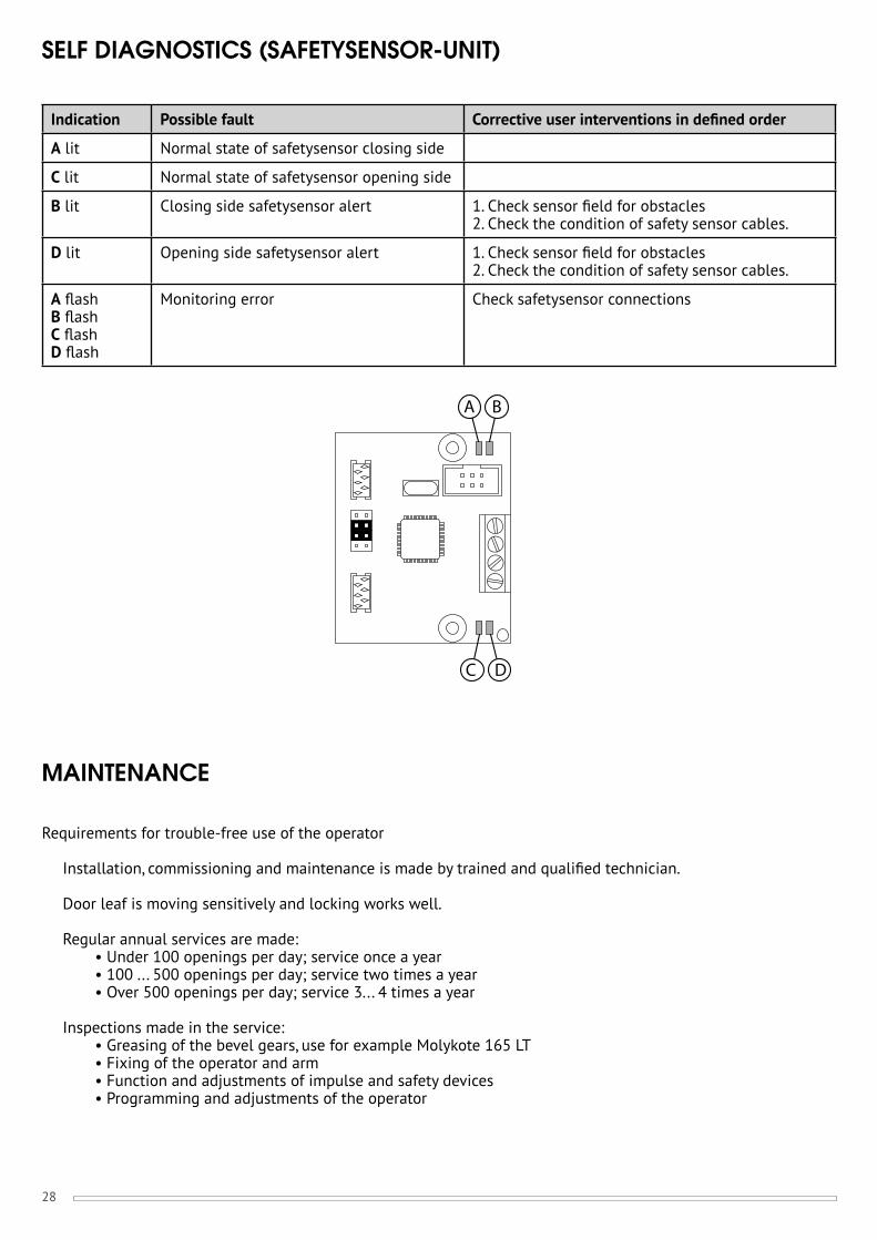
SELF DIAGNOSTICS (SAFETYSENSOR-UNIT)
A B
DC
Indication Possible fault Corrective user interventions in defi ned order
A lit Normal state of safetysensor closing side
C lit Normal state of safetysensor opening side
B lit Closing side safetysensor alert 1. Check sensor fi eld for obstacles2. Check the condition of safety sensor cables.
D lit Opening side safetysensor alert 1. Check sensor fi eld for obstacles2. Check the condition of safety sensor cables.
A fl ashB fl ashC fl ashD fl ash
Monitoring error Check safetysensor connections
29
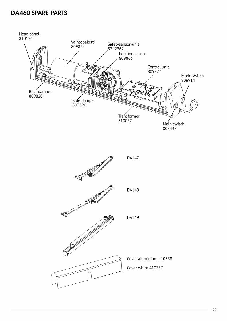
DA460 SPARE PARTS
Head panel810174
Vaihtopaketti809854
Position sensor809863
Control unit809877
Mode switch806914
Rear damper809820
Side damper803520
Transformer810057
Main switch807437
DA147
DA148
DA149
Cover aluminium 410358
Cover white 410357
Safetysensor-unit5742362

30

31

Nim
ike:
931
2568
Pä
iväy
s: 0
5/20
15M
JP /
25.
5.20
15 /
InD
esig
n
This product contains materials, such as electronics, which require specialist recycling techniques.When the product is taken out of use, disassemble it and sort and recycle the different materials as per valid recycling instructions.
We reserve the right to make alterations to the products described in this leaflet.
An ASSA ABLOY Group brand
MANUFACTURER:ABLOY secures people, property, and business operations on land, at sea, and in the air – in all circumstances.
ASSA ABLOY is the global leader in door opening solutions, dedicated to satisfying end-user needs for security, safety and convenience.
Abloy OyWahlforssinkatu 20
P.O. Box 108FI-80101 Joensuu | Finland
Tel. +358 20 599 2501WWW.ABLOY.COM