Embed Size (px)
Citation preview

About the Centuri Orion™
The Orion was released in the 1971 Centuri Catalog in
late 1970. Introduced as a big and highly detailed single
engine demonstration rocket, the Orion used parts from
the Saturn 1B and Saturn V kits to give it the look of a
futuristic NASA interplanetary exploration rocket. The
first production models used a balsa nose cone and six
balsa pod cones. The pod cones were replaced with
plastic just after release and the large nose cone was
replaced with a plastic version several months later. It
was released as Catalog No. KC-8 and retailed for $4.95.
The Semroc Retro-Repro™ Centuri Orion™ is very close
to the original. All the nose cones are balsa like the origi-
nal version. The vacuform wraps are replaced with em-
bossed glossy card stock and balsa parts to provide for
greater detailing. The parachute is reduced to 16” for
less drift with the lower weight.
Copyright © 2010 Semroc Astronautics Corporation
Box 1271 Knightdale, NC 27545 (919) 266-1977
About Centuri Engineering
Centuri Engineering Company was started in 1961 by
Leroy (Lee) Piester in his garage while he was still in
college in Phoenix, Arizona. With his wife, Betty, they
built Centuri into one of the largest model rocket compa-
nies ever.
Centuri was known for its unusual and innovative de-
signs, producing over 140 different kits with something
for every model rocketeer. They also produced model
rocket engines and pioneered the modern composite
high powered engines with their Enerjet line.
Centuri Engineering was sold to Damon in the late
1960’s and shared the same parent corporation with
Estes Industries, the largest model rocket company in
the world. The Centuri product line was kept separate
from the Estes line until 1983. A few of the old kits have
been reissued by Estes since then, but for the most part,
Centuri Engineering Company lives today only in the
dreams of the senior members of the model rocket com-
munity.
March 7, 2010
Made in the U.S.A by Semroc Astronautics Corporation - Knightdale, N.C. 27545
Centuri Orion™
Kit No. KV-41
Specifications Body Diameter 2.04” (5.2 cm) Length 22.6” (57.4 cm) Fin Span 7.3” (18.6 cm) Net Weight 3.1 oz. (88.0 g)
Engine Approx. Altitude B6-2 175’ C6-3 475’
PARACHUTE RECOVERY
FUTURISTIC SCALE-LIKE
EASY TO BUILD
FUN DEMOS
BALSA FINS & NOSE CONE
TM
What is a Retro-Repro?
A Retro-Repro™ is a retro reproduction of an out-of-
production model rocket kit. It is a close approximation
of a full scale model of an early historically significant
model rocket kit from one of the many companies that
pioneered the hobby over the past half century. A Retro-
Repro™ is not a true clone or identical copy of the origi-
nal. It incorporates improvements using modern tech-
nology, while keeping the flavor and build appeal of the
early kits.
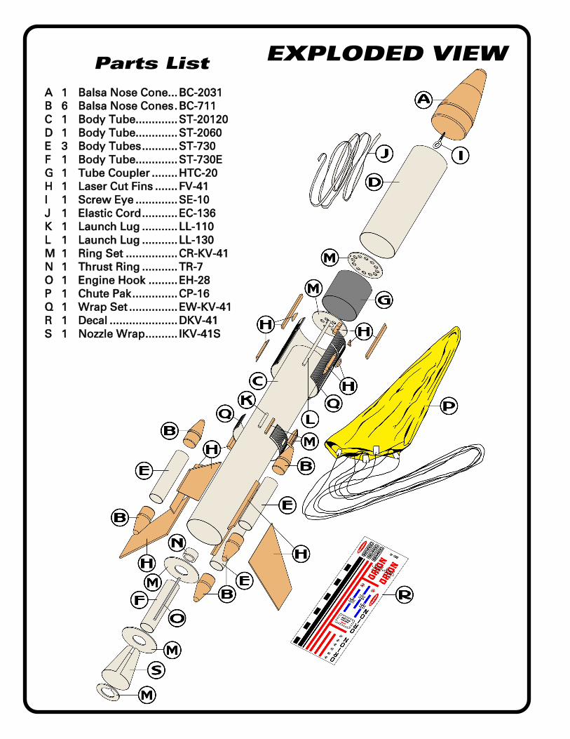
EXPLODED VIEW Parts List
A 1 Balsa Nose Cone ... BC-2031
B 6 Balsa Nose Cones . BC-711
C 1 Body Tube............. ST-20120
D 1 Body Tube............. ST-2060
E 3 Body Tubes ........... ST-730
F 1 Body Tube............. ST-730E
G 1 Tube Coupler ........ HTC-20
H 1 Laser Cut Fins ....... FV-41
I 1 Screw Eye ............. SE-10
J 1 Elastic Cord ........... EC-136
K 1 Launch Lug ........... LL-110
L 1 Launch Lug ........... LL-130
M 1 Ring Set ................ CR-KV-41
N 1 Thrust Ring ........... TR-7
O 1 Engine Hook ......... EH-28
P 1 Chute Pak .............. CP-16
Q 1 Wrap Set ............... EW-KV-41
R 1 Decal ..................... DKV-41
S 1 Nozzle Wrap .......... IKV-41S

Centuri Orion KV-41 Page 3
TOOLS In addition to the parts supplied,
you will need the following tools to
assemble and finish this kit.
BEFORE YOU START!
Make sure you have all the parts
included in this kit that are listed
in the Parts List in the center of
these instructions. In addition to
the parts included in this kit,
you will also need the tools and
materials listed below. Read the
entire instructions before begin-
ning to assemble your rocket.
When you are thoroughly famil-
iar with these instructions, be-
gin construction. Read each
step and study the accompany-
ing drawings. Check off each
step as it is completed. In each
step, test-fit the parts together
before applying any glue. It is
sometimes necessary to sand
lightly or build-up some parts to
obtain a precision fit. If you are
uncertain of the location of
some parts, refer to the ex-
ploded view to the right. It is
important that you always en-
sure that you have adequate
glue joints.
1. These instructions are
presented in a logical order to
help you put your Centuri
Orion™ together quickly and
efficiently. Check off each step as
you complete it and we hope you
enjoy putting this kit together.
ASSEMBLY
2. Lightly sand each side of
the laser-cut fin sheets (FV-41).
Carefully push the laser-cut fins
from their sheets. Start at one
point on each fin and slowly and
gently work around the fin.
3. Stack all the similar fins in
a set. Line the set of fins up
squarely and sand the fins back
and forth over some fine sandpa-
per to get rid of the hold-in tabs
as shown below.
4. Round the leading and
trailing edges of each main fin
and the shortest end of the three
pod fins. Leave the tip and root
edges flat. The root edges will be
glued to the body tube. Use this
guide for sanding the smaller
pieces later. As the small pieces
are completed, it may be easier
to paint them before final assem-
bly.
FIN PREPARATION
ENGINE MOUNT
5. Bend the engine hook (EH-
28) slightly so it forms a slight
bow in the direction shown.
6. Insert one end of the en-
gine hook into the punched slit in
the engine tube (ST-730E). There
are three other tubes the same
size without the slit.
7. Mark the engine tube 1”
from the punched end.

Page 4 Centuri Orion KV-41
8. Glue the thrust ring (TR-7)
against the top of the engine
hook. After the ring is in place,
run a bead of glue around the
inside of the ring to protect it
from the ejection gases.
10. Apply a bead of glue
around the engine tube at the
mark. Apply another bead of glue
along the engine hook near its
middle. A small piece of masking
tape can be used to hold the
hook in place.
NOZZLE
9. Cut out the nozzle shroud
from its sheet. Form it into a cone
and apply a small amount of glue
to the tab on one end as denoted
by the dotted line. Attach the free
end over the glue so its end is
even with the dotted line and
hold in place until the glue sets.
Some glues will shrink and warp
the paper, so white glue or CA
glue is recommended.
11. Slide the nozzle shroud
over the engine tube until the
mark is even with the small end
of the shroud.
12. Carefully remove the
smallest ring from the laser-cut
ring sheet (CR-KV-41). Slide it
over the end of the engine tube
and inside the nozzle shroud. Ap-
ply a thin bead of glue around
the joints formed by the ring and
tube and ring and shroud. Make
sure the engine hook moves
freely in the slot.
13. Carefully remove the lar-
ger centering ring with a small
notch on the inner hole. Slide it
over the end of the engine tube
aligning the notch over the en-
gine hook. Position it against the
end of the nozzle shroud. Apply a
thin bead of glue around the
joints formed by the ring and
tube and ring and shroud. Allow
to dry.
14. Carefully remove the lar-
ger centering ring with only one
hole. Slide it over the end of the
engine tube until it leaves about
1/16” of the engine tube exposed.
Apply a thin bead of glue around
the joints on both sides of the
ring. Allow to dry in a vertical
position.
EJECTION BAFFLE
15. Carefully remove the re-
maining baffle rings from the la-
ser-cut sheet. Punch all the
smaller holes free. Using the ring
with the most holes (top of baf-
fle), insert one end of the elastic
shock cord (EC-136) into the
small slot near the edge. Tie a
knot in the end and pull it until
the knot is against the ring. Apply
a generous bead of glue on the
knot. Insert into one end of the
coupler tube (HTC-20).
16. Adjust the ring until it is
about 1/16” inside the coupler
tube. Apply a generous bead of
glue around both edges of the
baffle ring against the coupler
tube.

Centuri Orion KV-41 Page 5
20. Stand the body tube as-
sembly on the fin guide below
with the baffle end pointed up-
ward and away from the guide.
Place seven marks on the tube at
the positions indicated. Place a
mark LL on the line that will be
used for the launch lugs. Find a
convenient channel or groove
such as a partially open drawer, a
door jamb (as shown,) or a piece
of molding. Using the channel,
extend the LL mark the full length
of the tube. Extend the six other
marks about 4” from the bottom
of the tube to provide lines for
aligning the fins.
MARK TUBE
17. Apply a bead of glue in-
side the opposite end and care-
fully insert the remaining baffle
ring. Use a pencil or small dowel
to help get it in position about
1/16” inside the coupler tube. Ap-
ply a thin bead of glue around
the joint. After the assembly is
dry, apply a layer of glue to the
outside of the bottom ring to pro-
tect it from hot gasses.
18. Mark the coupler tube
about 7/8” from either end. Apply
a bead of glue inside one end of
the smaller body tube section (ST
-2060). Slide the elastic cord
through the tube and insert the
top end of the coupler in the
body tube until the mark is even
with the end of the tube. Con-
tinue with the next step before
the glue dries.
19. Apply a bead of glue in-
side one end of the large body
tube (ST-20120). Slide the baffle
into the end of the tube until the
tubes are even with each other.
Roll the assembly on a flat sur-
face to make sure the tubes are
parallel with each other. Allow to
ENGINE MOUNT
21. Apply a generous bead of
glue about 3/4” inside the end of
the body tube. Insert the engine
mount until the bottom ring is
about 1” inside the body tube
and about 1” of the nozzle is out-
side the tube. Allow to dry.
22. Apply a bead of glue
around the bottom (exposed)
centering ring joint using a piece
of scrap balsa or a cotton swab.
Allow to dry.
TANK ASSEMBLY
23. Apply a bead of glue in-
side each end of one of the small
body tubes (ST-730). Insert a
small nose cone (BC-711) in each
end. Allow the assembly to dry.
Repeat for the other two tank as-
semblies. Lay them aside to com-
pletely dry.
completely dry while slowly ro-
tating the tube to make sure any
excess glue is uniformly distrib-
uted inside the tube.

Page 6 Centuri Orion KV-41
25. Apply glue to the longest
edge of one of the tank assem-
blies and position it along the
line just below the LL line as
shown. Remove it, allow to al-
most dry, re-glue and reposition
it. Allow this tank assembly to
dry before proceeding, checking
for perpendicular positioning
with the main body tube.
28. After the fin assembly is
completely dry, run a small bead
of glue along both sides of each
fin-body tube joint. Using your
forefinger, smooth the glue into
fillets. Allow this assembly to dry
in a vertical position.
ATTACH FINS APPLY FILLETS
24. Place a mark along the
side of a tank assembly using a
channel or drawer slide. Apply
glue to the shorter of the two
long sides of one of the pod fins
and position it along the line. Re-
move the fin, set it aside and al-
low it to almost dry, apply addi-
tional glue, and reposition. Re-
peat for the other two tank as-
semblies. If you follow these in-
structions, the fins will not re-
quire much additional work to
keep them aligned. Allow the fins
to completely dry, checking care-
fully to make sure they are paral-
lel with the body tube.
26. Apply glue to one of the
main fins and position it along
the line just above the LL line as
shown. Remove it, allow it to al-
most dry, re-apply glue and repo-
sition it. Allow this fin to dry be-
fore proceeding, checking for
perpendicular positioning with
the main body tube.
27. Alternate the remaining
tank assemblies and main fins,
making sure they are are parallel
with the main body tube. Allow
everything to dry completely.
DETAIL PARTS
29. Locate the three ullage
rocket fairings (Part AF). They
should be sanded to a circular
shape on the tip by rounding the
front and back sides. Leave the
bottom flat.
30. Locate the three retro-
rocket housings (Part H). Sand
them so the front and back have
a rounded conical shape and the
middle part is rounded as shown.
Leave the bottom flat.
31. Locate the two chilldown
pump fairings (Part BA). Sand
them so the front and back have
a rounded conical shape and the
middle part is rounded as shown.
Leave the bottom flat.
32. Locate the LH2 fill fairing
(Part K). Sand it so the front and
back sections have a slope using
the very faint laser cut marks or
hold-in tabs as guides. Leave the
middle part and the bottom flat.
33. Locate the two electrical
tunnels (Part Z). Sand them so
the front section has a 45 degree
slope. Leave the other sides flat.
Note: A small emery board will
make the shaping of the follow-
ing parts much easier.

Centuri Orion KV-41 Page 7
34. Locate the rear electrical
tunnel (Part Q). Sand it with a 45
degree slope on the front and
rear edge. Leave the other sides
flat.
35. Locate all four pieces of
the secondary APS fairings (Part
M). Glue two of the pieces to-
gether as shown. Sand all the
edges except the longest
(bottom) edge rounded. Leave
the bottom edge flat. Repeat with
the remaining two pieces to
make a second fairing.
36. Locate the top and bot-
tom sections of the two primary
APS fairings (Part AD). Glue a top
piece on one of the bottom
pieces, centered and even with
the back edge. Sand the side
edges rounded and sand the top
piece to a half round shape. Sand
a slope on the front as shown in
the third drawing. Leave the rear
flat as shown in the fourth draw-
ing.
APPLY WRAPS
37. Start with the bottom
(smaller) wrap. Fit it around the
main body tube, 4-1/4” from the
bottom and with the ends aligned
38. Continue with the top
wrap. Fit it around the main body
tube, 4-3/8” from the top and
with the ends aligned with the LL
line. Make sure the wrap has the
smaller section toward the top of
the body tube. Apply a thin film
of white glue on the dull side and
place it around the body tube as
it was aligned during the test fit-
ting.
APPLY DETAILS
39. Position the model as
shown with the LL line pointing
directly downward. Viewing the
model from the bottom, all the
parts will be positioned as the
model is turned clockwise. The
first part that will be applied is
one of the primary APS pieces
(Part AD). It will be aligned on the
first wide flat area, with the bot-
tom even with the end of the cor-
rugations and the pointed end
extending beyond the top edge
of the wrap onto the body tube.
40. Rotate the model slightly
clockwise. Apply glue to the bot-
tom of the rear electrical tunnel
(Part Q) and apply it to the next
flat area. It will overhang slightly
off the back and onto the body
tube.
41. Rotate the model clock-
wise until the second wide flat
spot appears. The second pri-
mary APS piece (Part AD) will be
applied. Align it on the wide flat
area, with the bottom even with
the end of the corrugations and
the pointed end extending be-
yond the top edge of the wrap
onto the body tube.
with the LL line. There is a top
and bottom on each wrap. Make
sure the first flat area on the
wrap is positioned as shown. Ap-
ply a thin film of white glue on
the dull side and place it around
the body tube as it was aligned
during test fitting.
Page 8 Centuri Orion KV-41
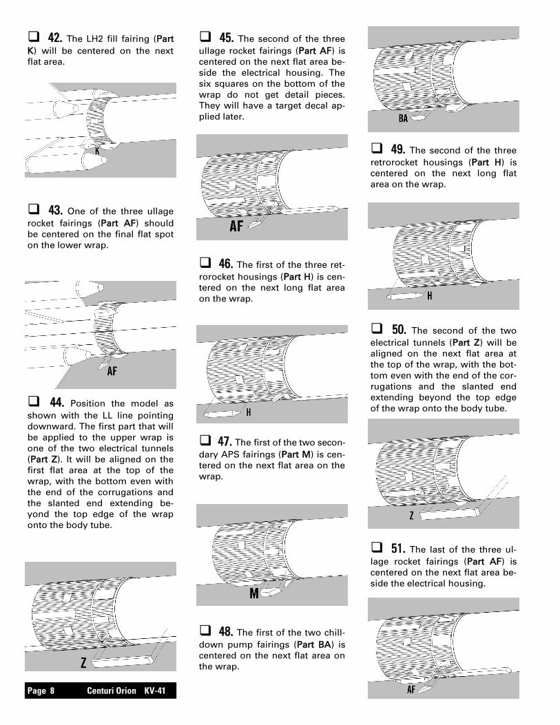
42. The LH2 fill fairing (Part
K) will be centered on the next
flat area.
43. One of the three ullage
rocket fairings (Part AF) should
be centered on the final flat spot
on the lower wrap.
44. Position the model as
shown with the LL line pointing
downward. The first part that will
be applied to the upper wrap is
one of the two electrical tunnels
(Part Z). It will be aligned on the
first flat area at the top of the
wrap, with the bottom even with
the end of the corrugations and
the slanted end extending be-
yond the top edge of the wrap
onto the body tube.
45. The second of the three
ullage rocket fairings (Part AF) is
centered on the next flat area be-
side the electrical housing. The
six squares on the bottom of the
wrap do not get detail pieces.
They will have a target decal ap-
plied later.
46. The first of the three ret-
rorocket housings (Part H) is cen-
tered on the next long flat area
on the wrap.
49. The second of the three
retrorocket housings (Part H) is
centered on the next long flat
area on the wrap.
47. The first of the two secon-
dary APS fairings (Part M) is cen-
tered on the next flat area on the
wrap.
48. The first of the two chill-
down pump fairings (Part BA) is
centered on the next flat area on
the wrap.
50. The second of the two
electrical tunnels (Part Z) will be
aligned on the next flat area at
the top of the wrap, with the bot-
tom even with the end of the cor-
rugations and the slanted end
extending beyond the top edge
of the wrap onto the body tube.
51. The last of the three ul-
lage rocket fairings (Part AF) is
centered on the next flat area be-
side the electrical housing.

Centuri Orion KV-41 Page 9
55. Apply a bead of glue to the
short launch lug (LL-110) and apply it
over the joint of the lower wrap on
the LL line. Apply a bead of glue on
the long launch lug (LL-130) and ap-
ply it over the joint of the upper wrap
on the LL line. Sight from one end to
make sure they are parallel with the
line.
58. When the fillets have
dried, prepare balsa surfaces for
a smooth professional looking
finish. Fill the wood grain with
balsa fillercoat or sanding sealer,
When dry, sand with fine sandpa-
per. Repeat until smooth.
FINISHING
59. After all balsa surfaces
have been prepared, wipe off all
balsa dust with a dry cloth. First
spray the model with an enamel
primer. Choose a high visibility
color like white for the final color.
60. Spray painting your
model with a fast-drying enamel
will produce the best results. PA-
TIENCE…is the most important
ingredient. Use several thin
coats, allowing each coat to com-
pletely dry before the next coat.
Start each spray a few inches
above the model and end a few
inches below the model. Keep
the can about 12” away and use
quick light coats. The final coat
can be a little heavier to give the
model a glossy wet-looking fin-
ish.
57. Assemble the chute (CP-
16) using instructions included
with the chute. Pull the lines tight
on the chute and make sure they
are all of equal length. Attach the
chute by tying them to the screw
eye. Put a drop of glue on the
joint to keep the lines from mov-
ing. Attach the free end of the
elastic cord to the screw eye. Put
a drop of glue on that joint as
well.
FINAL ASSEMBLY
This completes the assembly of your 56. Insert the nose cone (BC-
2031) in the body tube and check
for proper fit. The nose cone
should be snug to hold itself in
alignment. If it is too loose, add
masking tape. If it is too tight,
sand the shoulder slightly. Turn
the screw eye (SE-10) into the
cone and remove. Add a drop of
glue in the hole and reinsert the
screw eye.
LAUNCH LUGS
NOSE CONE
53. The last of the three retro-
rocket housings (Part H) is cen-
tered on the next long flat area
on the wrap.
54. The last of the two chill-
down pump fairings (Part BA) is
centered on the final flat area on
the wrap.
52. The last of the two secon-
dary APS fairings (Part M) is cen-
tered on the next flat area on the
wrap.
Page 10 Centuri Orion KV-41
FLIGHT PREPPING
65. Refer to the model rocket
engine manufacturer’s instruc-
tions to complete the engine
prepping. Different engines have
different igniters and methods of
hooking them up to the launch
controllers.
66. Carefully check all parts
of your rocket before each flight
as a part of your pre-flight check-
list. Launch the Centuri Orion™
from a 1/8” diameter by 36” long
launch rod.
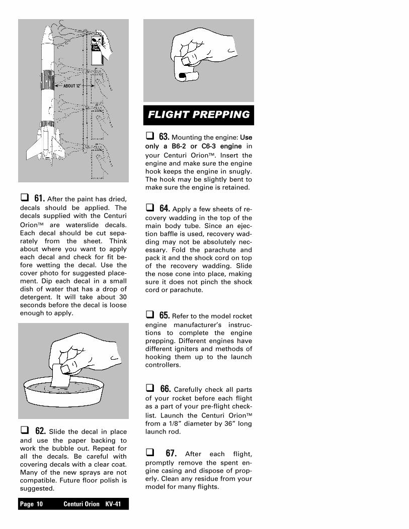
63. Mounting the engine: Use
only a B6-2 or C6-3 engine in
your Centuri Orion™. Insert the
engine and make sure the engine
hook keeps the engine in snugly.
The hook may be slightly bent to
make sure the engine is retained.
64. Apply a few sheets of re-
covery wadding in the top of the
main body tube. Since an ejec-
tion baffle is used, recovery wad-
ding may not be absolutely nec-
essary. Fold the parachute and
pack it and the shock cord on top
of the recovery wadding. Slide
the nose cone into place, making
sure it does not pinch the shock
cord or parachute.
61. After the paint has dried,
decals should be applied. The
decals supplied with the Centuri
Orion™ are waterslide decals.
Each decal should be cut sepa-
rately from the sheet. Think
about where you want to apply
each decal and check for fit be-
fore wetting the decal. Use the
cover photo for suggested place-
ment. Dip each decal in a small
dish of water that has a drop of
detergent. It will take about 30
seconds before the decal is loose
enough to apply.
62. Slide the decal in place
and use the paper backing to
work the bubble out. Repeat for
all the decals. Be careful with
covering decals with a clear coat.
Many of the new sprays are not
compatible. Future floor polish is
suggested.
67. After each flight,
promptly remove the spent en-
gine casing and dispose of prop-
erly. Clean any residue from your
model for many flights.