Embed Size (px)
Citation preview
Slide 1 of 72©2016, 2019 ∙ Table of Contents
• About the Instructor • About the Sponsor • Ask an Expert
< >
This Online Learning Seminar is available
through a professional courtesy provided by:
Wire-Bond400 Rountree Road
Charlotte, NC 28217
Tel: (800) 849-6722
Email: [email protected]
Web: www.wirebond.com
START
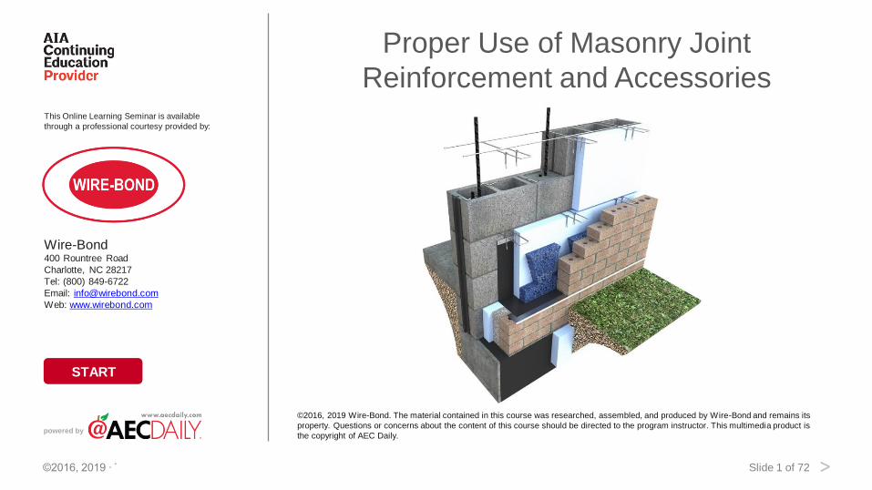
Proper Use of Masonry Joint
Reinforcement and Accessories
©2016, 2019 Wire-Bond. The material contained in this course was researched, assembled, and produced by Wire-Bond and remains its
property. Questions or concerns about the content of this course should be directed to the program instructor. This multimedia product is
the copyright of AEC Daily.powered by
Slide 2 of 72©2016, 2019 ∙ Table of Contents
• About the Instructor • About the Sponsor • Ask an Expert
< >
Proper Use of Masonry Joint Reinforcement and Accessories
To ensure the current status of this course, including relevant association approvals, please view the course details here.
The American Institute of Architects
Course No. AEC1342
This program qualifies for 1.0 LU/HSW Hour
Course Expiry Date: 12/04/2022
AEC Daily Corporation is a registered provider of AIA-approved continuing education under Provider Number J624. All registered AIA CES
Providers must comply with the AIA Standards for Continuing Education Programs. Any questions or concerns about this provider or this
learning program may be sent to AIA CES ([email protected] or (800) AIA 3837, Option 3).
This learning program is registered with AIA CES for continuing professional education. As such, it does not include content that may be
deemed or construed to be an approval or endorsement by the AIA of any material of construction or any method or manner of handling,
using, distributing, or dealing in any material or product.
AIA continuing education credit has been reviewed and approved by AIA CES. Learners must complete the entire learning program to
receive continuing education credit. AIA continuing education Learning Units earned upon completion of this course will be reported to AIA
CES for AIA members. Certificates of Completion for both AIA members and non-AIA members are available upon completion of the test.
Slide 3 of 72©2016, 2019 ∙ Table of Contents
• About the Instructor • About the Sponsor • Ask an Expert
< >
AEC Daily Corporation has met the standards and requirements of the Registered
Continuing Education Program. Credit earned on completion of this program will be
reported to RCEP at RCEP.net. A certificate of completion will be issued to each
participant. As such, it does not include content that may be deemed or construed to be
an approval or endorsement by the RCEP.
Slide 4 of 72©2016, 2019 ∙ Table of Contents
• About the Instructor • About the Sponsor • Ask an Expert
< >
How to Use This Online Learning Course
To view this course, use the arrows at the bottom of each slide or the up and down arrow keys on your keyboard.
To print or exit the course at any time, press the ESC key on your keyboard. This will minimize the full-screen
presentation and display the menu bar.
Within this course is a test password that you will be required to enter in order to proceed with the online test. Please
be sure to remember or write down this test password so that you have it available for the test.
To receive a certificate indicating course completion, refer to the instructions at the end of the course.
For additional information and post-seminar assistance, click on any of the logos and icons within a page or any of the
links at the top of each page.
Slide 5 of 72©2016, 2019 ∙ Table of Contents
• About the Instructor • About the Sponsor • Ask an Expert
< >
Purpose and Learning Objectives
Purpose: Ensuring proper use of methods and materials allows masonry walls to perform well and enjoy a long life. Use
of masonry joint reinforcement and accessories is an essential part of this. This course provides a brief history of solid
masonry walls leading up to the modern cavity walls of today, including a discussion of the basic working knowledge of
masonry joint reinforcing, structural codes, and moisture control in cavity wall construction.
Learning Objectives:
At the end of this program, participants will be able to:
• describe the history of solid masonry walls and how they have shifted into today’s cavity walls to meet the evolving
needs of modern societies
• analyze the types of joint reinforcing including their design, function, correct application, and installation, as well as
their role in ensuring the safety and performance of masonry walls
• evaluate the types of adjustable ties and stone anchors available, including how to choose the proper type for a
specific project and proper installation techniques, and
• explain the types of flashing, mortar dropping collection devices, and weeps used in masonry walls and how these
devices deal with possible water intrusion to ensure the life of the masonry wall.
Slide 6 of 72©2016, 2019 ∙ Table of Contents
• About the Instructor • About the Sponsor • Ask an Expert
< >
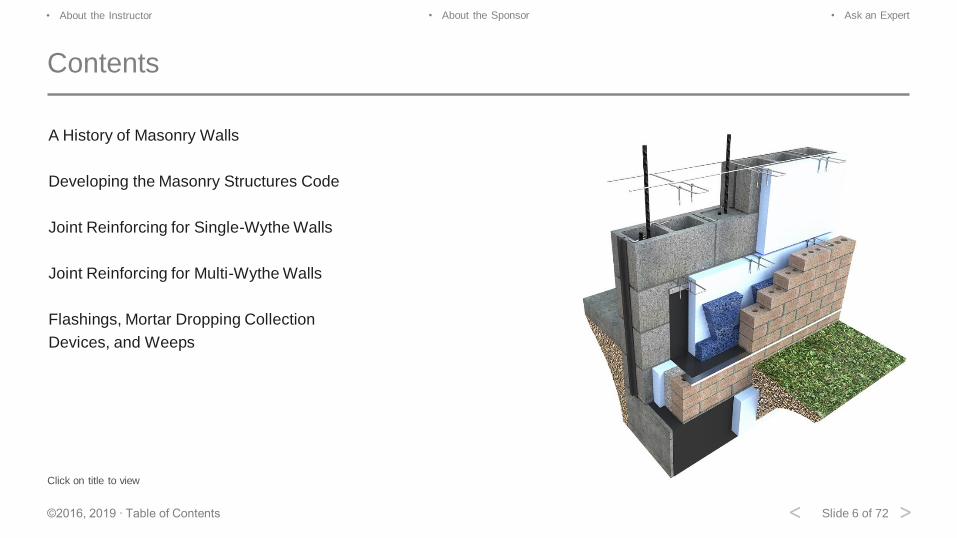
Contents
A History of Masonry Walls
Developing the Masonry Structures Code
Joint Reinforcing for Single-Wythe Walls
Joint Reinforcing for Multi-Wythe Walls
Flashings, Mortar Dropping Collection
Devices, and Weeps
Click on title to view
Slide 7 of 72©2016, 2019 ∙ Table of Contents
• About the Instructor • About the Sponsor • Ask an Expert
< >
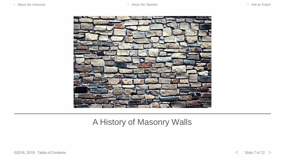
A History of Masonry Walls
Slide 8 of 72©2016, 2019 ∙ Table of Contents
• About the Instructor • About the Sponsor • Ask an Expert
< >
A Brief History of Masonry Walls
No one knows exactly when the first wall was built; perhaps cavemen and cavewomen felt they needed to protect
themselves from wind, rain, and various animals that might try to get into their caves. Stone or dry mud from a lakebed
would have been stacked to create some type of wall.
Although somewhat effective, these walls still required mud as a mortar to help support the stones or pieces of dry mud
from a lakebed as the wall grew in height.
As time went on, people found that the mud alone was not sufficient as the water evaporated from the mixture. The mud
would crack and fall out. In an effort to reinforce the mud/mortar, various grasses, weeds, and even horsehair were
added to the mix. This mix was also used as “chinking,” the reinforced material placed between the logs of a log cabin
that helps keep the wind, rain, and cold outside.
Slide 9 of 72©2016, 2019 ∙ Table of Contents
• About the Instructor • About the Sponsor • Ask an Expert
< >
Mesopotamia
6,000 years ago the Mesopotamians built the world’s first walled cities.
These walls used clay masonry units of special shapes and a running bond pattern. A running bond pattern is where the
next row of bricks is laid across the two ends of the bricks below. This pattern helped strengthen the wall from horizontal
wind loads and is still the most common pattern used today.
It should be noted that as the wall grew in height, the wall’s overall thickness also grew in an effort to carry the loads from
above.
Slide 10 of 72©2016, 2019 ∙ Table of Contents
• About the Instructor • About the Sponsor • Ask an Expert
< >
Pyramids of Giza
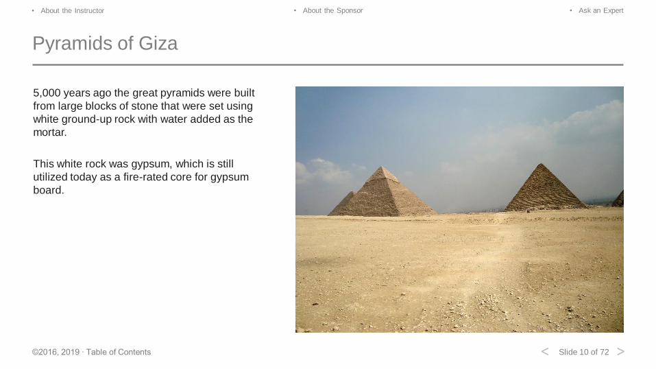
5,000 years ago the great pyramids were built
from large blocks of stone that were set using
white ground-up rock with water added as the
mortar.
This white rock was gypsum, which is still
utilized today as a fire-rated core for gypsum
board.
Slide 11 of 72©2016, 2019 ∙ Table of Contents
• About the Instructor • About the Sponsor • Ask an Expert
< >
Mud Brick
Eventually, builders decided that they needed a more uniform shape in creating their mud brick. So they created a wood
form in which they not only added the mud and local silt, but also helped reinforce the bricks by using weeds, grasses, or
even horsehair.
We still reinforce our masonry structures today with additives like chopped glass fiber, ceramic fiber, and wire welded
mesh in things like concrete slabs and sidewalks. These wood-formed and sun-baked masonry units are still done in some
areas around the world.
Slide 12 of 72©2016, 2019 ∙ Table of Contents
• About the Instructor • About the Sponsor • Ask an Expert
< >
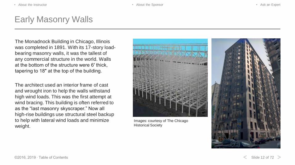
Early Masonry Walls
The Monadnock Building in Chicago, Illinois
was completed in 1891. With its 17-story load-
bearing masonry walls, it was the tallest of
any commercial structure in the world. Walls
at the bottom of the structure were 6′ thick,
tapering to 18″ at the top of the building.
The architect used an interior frame of cast
and wrought iron to help the walls withstand
high wind loads. This was the first attempt at
wind bracing. This building is often referred to
as the “last masonry skyscraper.” Now all
high-rise buildings use structural steel backup
to help with lateral wind loads and minimize
weight.
Images: courtesy of The Chicago
Historical Society
Slide 13 of 72©2016, 2019 ∙ Table of Contents
• About the Instructor • About the Sponsor • Ask an Expert
< >
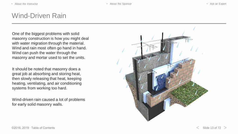
Wind-Driven Rain
One of the biggest problems with solid
masonry construction is how you might deal
with water migration through the material.
Wind and rain most often go hand in hand.
Wind can push the water through the
masonry and mortar used to set the units.
It should be noted that masonry does a
great job at absorbing and storing heat,
then slowly releasing that heat, keeping
heating, ventilating, and air conditioning
systems from working too hard.
Wind-driven rain caused a lot of problems
for early solid masonry walls.
Slide 14 of 72©2016, 2019 ∙ Table of Contents
• About the Instructor • About the Sponsor • Ask an Expert
< >
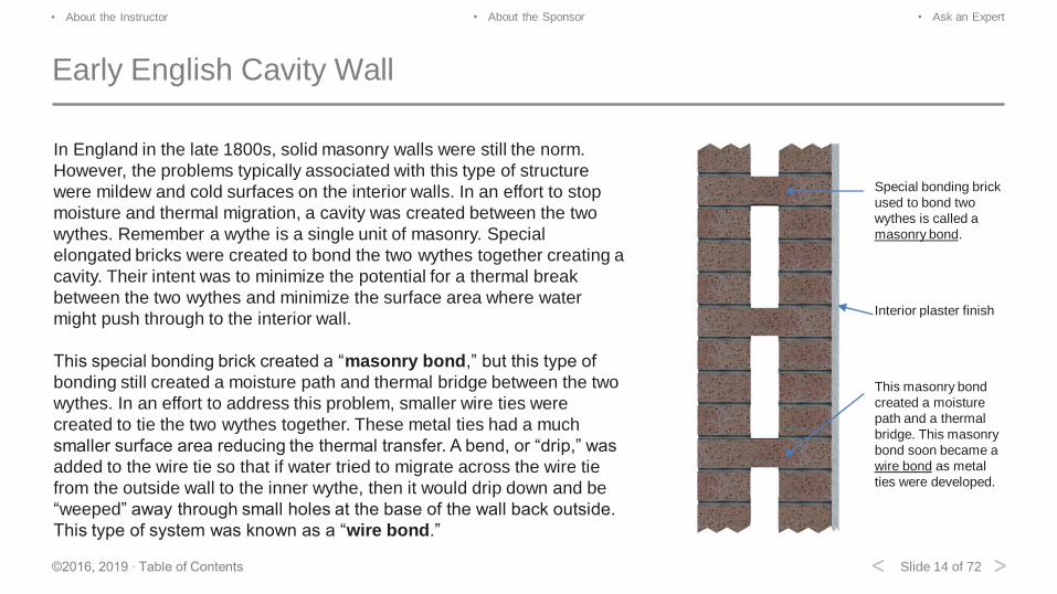
Early English Cavity Wall
In England in the late 1800s, solid masonry walls were still the norm.
However, the problems typically associated with this type of structure
were mildew and cold surfaces on the interior walls. In an effort to stop
moisture and thermal migration, a cavity was created between the two
wythes. Remember a wythe is a single unit of masonry. Special
elongated bricks were created to bond the two wythes together creating a
cavity. Their intent was to minimize the potential for a thermal break
between the two wythes and minimize the surface area where water
might push through to the interior wall.
This special bonding brick created a “masonry bond,” but this type of
bonding still created a moisture path and thermal bridge between the two
wythes. In an effort to address this problem, smaller wire ties were
created to tie the two wythes together. These metal ties had a much
smaller surface area reducing the thermal transfer. A bend, or “drip,” was
added to the wire tie so that if water tried to migrate across the wire tie
from the outside wall to the inner wythe, then it would drip down and be
“weeped” away through small holes at the base of the wall back outside.
This type of system was known as a “wire bond.”
Special bonding brick
used to bond two
wythes is called a
masonry bond.
Interior plaster finish
This masonry bond
created a moisture
path and a thermal
bridge. This masonry
bond soon became a
wire bond as metal
ties were developed.
Slide 15 of 72©2016, 2019 ∙ Table of Contents
• About the Instructor • About the Sponsor • Ask an Expert
< >
Brick Alternative
It has been found that these bends can reduce the strength of the tie
by as much as 50%. You will not find them in wire ties today. In the
late 1800s, a stronger alternative was created to replace the interior
brick wythe. In many instances, the exterior brick is considered a
curtain wall or brick veneer. The interior wythe is normally there to
carry the loads from above (wall, floor, roof, etc.). A single wythe of
brick was limited in its structural ability.
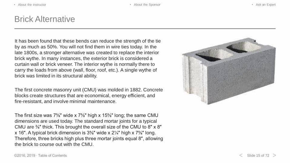
The first concrete masonry unit (CMU) was molded in 1882. Concrete
blocks create structures that are economical, energy efficient, and
fire-resistant, and involve minimal maintenance.
The first size was 7⅝″ wide x 7⅝″ high x 15⅝″ long; the same CMU
dimensions are used today. The standard mortar joints for a typical
CMU are ⅜″ thick. This brought the overall size of the CMU to 8″ x 8″
x 16″. A typical brick dimension is 3⅝″ wide x 2¼″ high x 7⅝″ long.
Therefore, three bricks high plus three mortar joints equal 8″, allowing
the brick to course out with the CMU.

Slide 16 of 72©2016, 2019 ∙ Table of Contents
• About the Instructor • About the Sponsor • Ask an Expert
< >
Concrete Exterior
Concrete blocks can be used as a finished exterior surface or as a structural backup wall for brick or stone veneers.
A CMU can also have a ceramic coating applied to the outside face. This is a good choice for some very dramatic effects
and it is easy to clean should graffiti become a problem.
Slide 17 of 72©2016, 2019 ∙ Table of Contents
• About the Instructor • About the Sponsor • Ask an Expert
< >
Today’s Block Backup Cavity Wall
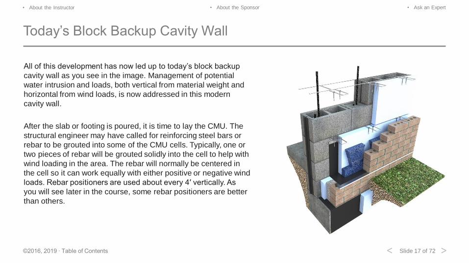
All of this development has now led up to today’s block backup
cavity wall as you see in the image. Management of potential
water intrusion and loads, both vertical from material weight and
horizontal from wind loads, is now addressed in this modern
cavity wall.
After the slab or footing is poured, it is time to lay the CMU. The
structural engineer may have called for reinforcing steel bars or
rebar to be grouted into some of the CMU cells. Typically, one or
two pieces of rebar will be grouted solidly into the cell to help with
wind loading in the area. The rebar will normally be centered in
the cell so it can work equally with either positive or negative wind
loads. Rebar positioners are used about every 4′ vertically. As
you will see later in the course, some rebar positioners are better
than others.
Slide 18 of 72©2016, 2019 ∙ Table of Contents
• About the Instructor • About the Sponsor • Ask an Expert
< >
Today’s Block Backup Cavity Wall
As the CMU is laid, masonry joint reinforcing is also laid every other course or 16″ on center vertically. Since 99% of the
projects specified call for ⅜″ mortar joints, it is important to remember that code dictates the masonry joint reinforcing no t
exceed half the thickness of the joint. Therefore, a ⅜″ mortar joint requires a 3/16″ maximum height for the masonry joint
reinforcing. This allows for better coverage of mortar around the masonry joint reinforcing. The masonry joint reinforcing
can be either 9 gauge (0.1483″) or 3/16″ diameter if more stringent loads are to be met.
Most CMU is 15⅝″ long with a center web. With a single ⅜″ mortared head joint, this brings the total length to 16″. If a
brick or stone veneer is to be used, then the tie will occur at 16″ on center at the center line or web of the CMU. This
brings the typical spacing for the ties to the exterior brick veneer to 16″ vertical and 16″ horizontal.
Code also states that any metal passing through the cavity of the wall shall be a minimum of 3/16″ in diameter. The cavity
is the distance from the back of the CMU to the back of the brick. Insulation and air space can take up some of this space,
but the cavity is still wythe to wythe.
Slide 19 of 72©2016, 2019 ∙ Table of Contents
• About the Instructor • About the Sponsor • Ask an Expert
< >
Today’s Block Backup Cavity Wall
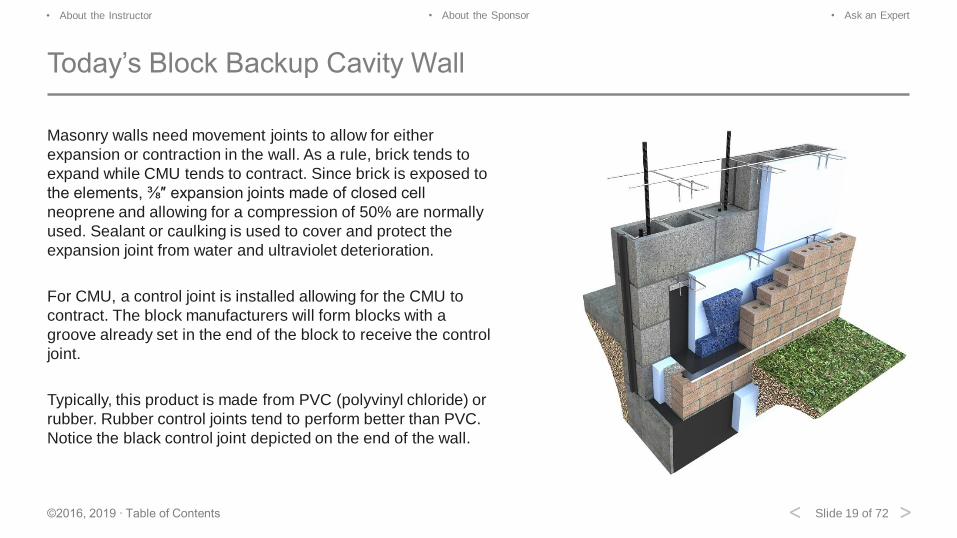
Masonry walls need movement joints to allow for either
expansion or contraction in the wall. As a rule, brick tends to
expand while CMU tends to contract. Since brick is exposed to
the elements, ⅜″ expansion joints made of closed cell
neoprene and allowing for a compression of 50% are normally
used. Sealant or caulking is used to cover and protect the
expansion joint from water and ultraviolet deterioration.
For CMU, a control joint is installed allowing for the CMU to
contract. The block manufacturers will form blocks with a
groove already set in the end of the block to receive the control
joint.
Typically, this product is made from PVC (polyvinyl chloride) or
rubber. Rubber control joints tend to perform better than PVC.
Notice the black control joint depicted on the end of the wall.
Slide 20 of 72©2016, 2019 ∙ Table of Contents
• About the Instructor • About the Sponsor • Ask an Expert
< >
Today’s Block Backup Cavity Wall
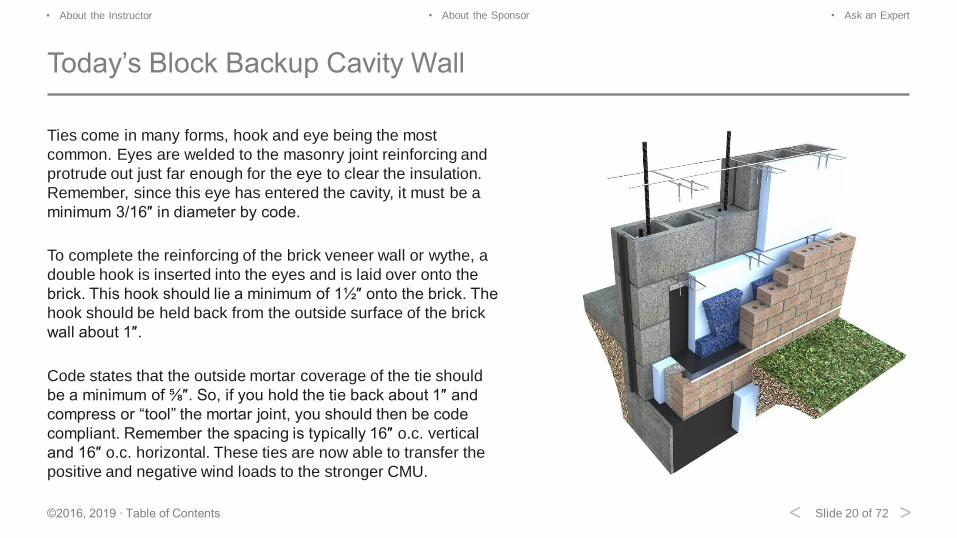
Ties come in many forms, hook and eye being the most
common. Eyes are welded to the masonry joint reinforcing and
protrude out just far enough for the eye to clear the insulation.
Remember, since this eye has entered the cavity, it must be a
minimum 3/16″ in diameter by code.
To complete the reinforcing of the brick veneer wall or wythe, a
double hook is inserted into the eyes and is laid over onto the
brick. This hook should lie a minimum of 1½″ onto the brick. The
hook should be held back from the outside surface of the brick
wall about 1″.
Code states that the outside mortar coverage of the tie should
be a minimum of ⅝″. So, if you hold the tie back about 1″ and
compress or “tool” the mortar joint, you should then be code
compliant. Remember the spacing is typically 16″ o.c. vertical
and 16″ o.c. horizontal. These ties are now able to transfer the
positive and negative wind loads to the stronger CMU.
Slide 21 of 72©2016, 2019 ∙ Table of Contents
• About the Instructor • About the Sponsor • Ask an Expert
< >
Today’s Block Backup Cavity Wall: Moisture Management
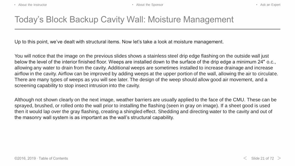
Up to this point, we’ve dealt with structural items. Now let’s take a look at moisture management.
You will notice that the image on the previous slides shows a stainless steel drip edge flashing on the outside wall just
below the level of the interior finished floor. Weeps are installed down to the surface of the drip edge a minimum 24″ o.c.,
allowing any water to drain from the cavity. Additional weeps are sometimes installed to increase drainage and increase
airflow in the cavity. Airflow can be improved by adding weeps at the upper portion of the wall, allowing the air to circulate.
There are many types of weeps as you will see later. The design of the weep should allow good air movement, and a
screening capability to stop insect intrusion into the cavity.
Although not shown clearly on the next image, weather barriers are usually applied to the face of the CMU. These can be
sprayed, brushed, or rolled onto the wall prior to installing the flashing (seen in gray on image). If a sheet good is used
then it would lap over the gray flashing, creating a shingled effect. Shedding and directing water to the cavity and out of
the masonry wall system is as important as the wall’s structural capability.
Slide 22 of 72©2016, 2019 ∙ Table of Contents
• About the Instructor • About the Sponsor • Ask an Expert
< >
Today’s Block Backup Cavity Wall
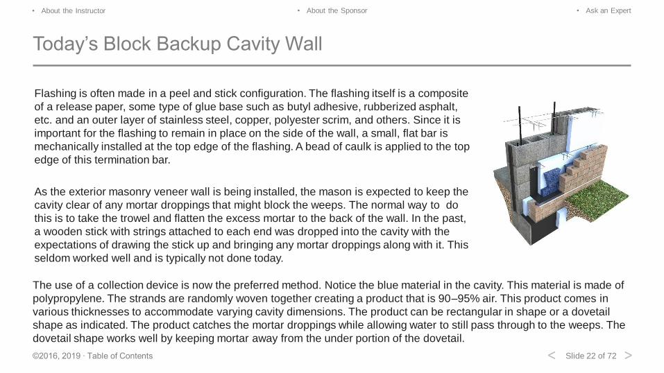
The use of a collection device is now the preferred method. Notice the blue material in the cavity. This material is made of
polypropylene. The strands are randomly woven together creating a product that is 90–95% air. This product comes in
various thicknesses to accommodate varying cavity dimensions. The product can be rectangular in shape or a dovetail
shape as indicated. The product catches the mortar droppings while allowing water to still pass through to the weeps. The
dovetail shape works well by keeping mortar away from the under portion of the dovetail.
Flashing is often made in a peel and stick configuration. The flashing itself is a composite
of a release paper, some type of glue base such as butyl adhesive, rubberized asphalt,
etc. and an outer layer of stainless steel, copper, polyester scrim, and others. Since it is
important for the flashing to remain in place on the side of the wall, a small, flat bar is
mechanically installed at the top edge of the flashing. A bead of caulk is applied to the top
edge of this termination bar.
As the exterior masonry veneer wall is being installed, the mason is expected to keep the
cavity clear of any mortar droppings that might block the weeps. The normal way to do
this is to take the trowel and flatten the excess mortar to the back of the wall. In the past,
a wooden stick with strings attached to each end was dropped into the cavity with the
expectations of drawing the stick up and bringing any mortar droppings along with it. This
seldom worked well and is typically not done today.
Slide 23 of 72©2016, 2019 ∙ Table of Contents
• About the Instructor • About the Sponsor • Ask an Expert
< >
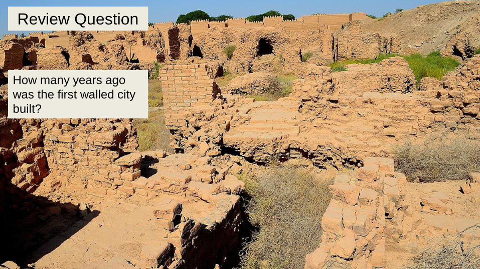
Review Question
How many years ago
was the first walled city
built?

Slide 24 of 72©2016, 2019 ∙ Table of Contents
• About the Instructor • About the Sponsor • Ask an Expert
< >
Answer
How many years ago
was the first walled city
built?
6000 years ago in
Mesopotamia.
Slide 25 of 72©2016, 2019 ∙ Table of Contents
• About the Instructor • About the Sponsor • Ask an Expert
< >
Developing the Masonry Structures Code
Slide 26 of 72©2016, 2019 ∙ Table of Contents
• About the Instructor • About the Sponsor • Ask an Expert
< >
Masonry Reinforcing
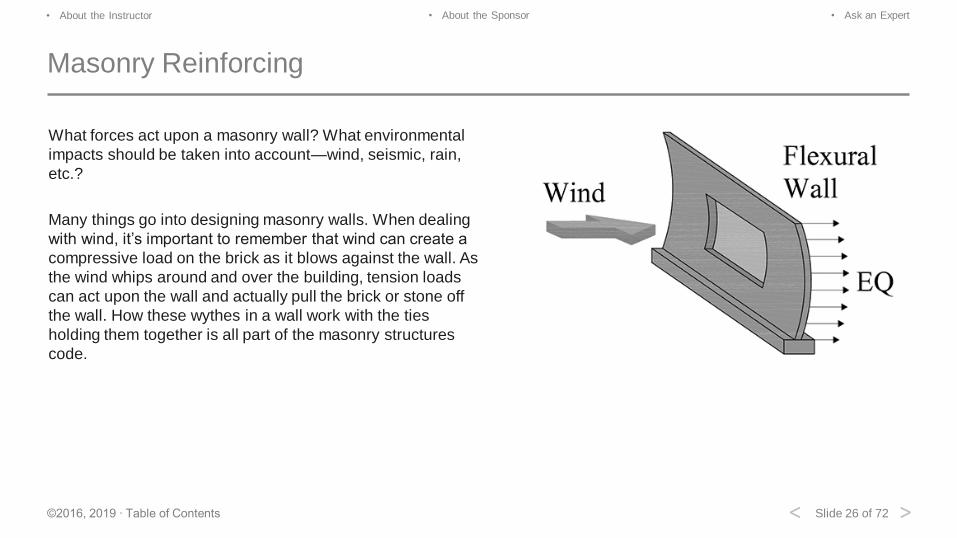
What forces act upon a masonry wall? What environmental
impacts should be taken into account—wind, seismic, rain,
etc.?
Many things go into designing masonry walls. When dealing
with wind, it’s important to remember that wind can create a
compressive load on the brick as it blows against the wall. As
the wind whips around and over the building, tension loads
can act upon the wall and actually pull the brick or stone off
the wall. How these wythes in a wall work with the ties
holding them together is all part of the masonry structures
code.
Slide 27 of 72©2016, 2019 ∙ Table of Contents
• About the Instructor • About the Sponsor • Ask an Expert
< >
Seismic Concerns
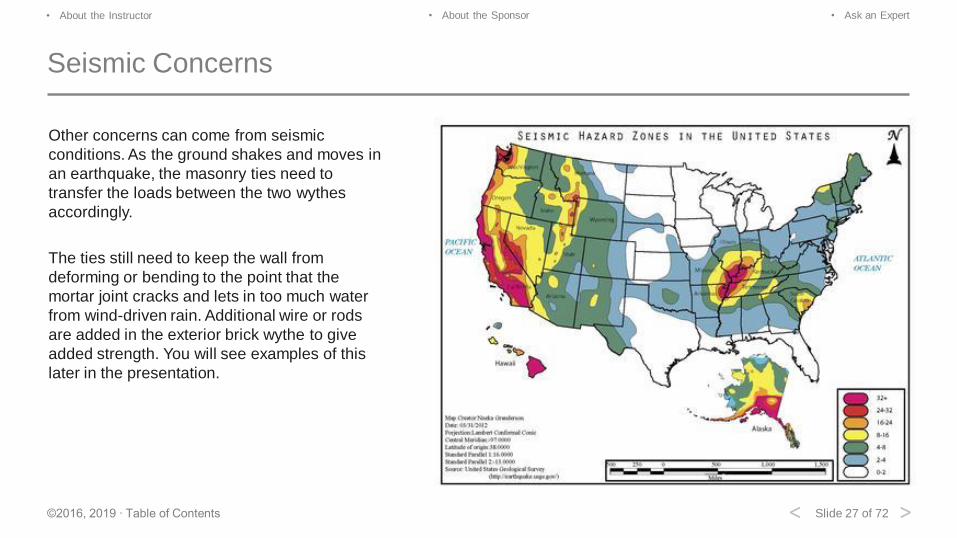
Other concerns can come from seismic
conditions. As the ground shakes and moves in
an earthquake, the masonry ties need to
transfer the loads between the two wythes
accordingly.
The ties still need to keep the wall from
deforming or bending to the point that the
mortar joint cracks and lets in too much water
from wind-driven rain. Additional wire or rods
are added in the exterior brick wythe to give
added strength. You will see examples of this
later in the presentation.
Slide 28 of 72©2016, 2019 ∙ Table of Contents
• About the Instructor • About the Sponsor • Ask an Expert
< >
Code Requirements
To understand more about the design of masonry walls and their
code requirements, you might look to the information provided by a
number of associations. The Brick Industry Association (BIA) is a
great first search for technical information and details,
www.gobrick.com.
The International Masonry Institute is developing BIM-M (Building
Information Modeling for Masonry), a source for the industry to come
together and offer architects, designers, and contractors good
generic details for the masonry industry, www.imiweb.org.
The Masonry Society www.masonrysociety.org, American Concrete
Institute www.concrete.org, Structural Engineering Institute
www.asce.org/structural-engineering/structural-engineering-institute,
and Mason Contractors Association of America
www.masoncontractors.org are all excellent resources.
Slide 29 of 72©2016, 2019 ∙ Table of Contents
• About the Instructor • About the Sponsor • Ask an Expert
< >
Building Code Requirements and Specifications for Masonry
Structures
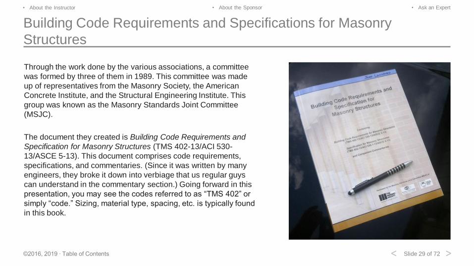
Through the work done by the various associations, a committee
was formed by three of them in 1989. This committee was made
up of representatives from the Masonry Society, the American
Concrete Institute, and the Structural Engineering Institute. This
group was known as the Masonry Standards Joint Committee
(MSJC).
The document they created is Building Code Requirements and
Specification for Masonry Structures (TMS 402-13/ACI 530-
13/ASCE 5-13). This document comprises code requirements,
specifications, and commentaries. (Since it was written by many
engineers, they broke it down into verbiage that us regular guys
can understand in the commentary section.) Going forward in this
presentation, you may see the codes referred to as “TMS 402” or
simply “code.” Sizing, material type, spacing, etc. is typically found
in this book.
Slide 30 of 72©2016, 2019 ∙ Table of Contents
• About the Instructor • About the Sponsor • Ask an Expert
< >
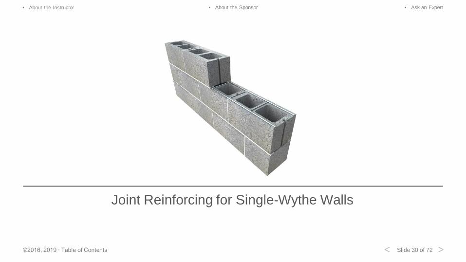
Joint Reinforcing for Single-Wythe Walls
Slide 31 of 72©2016, 2019 ∙ Table of Contents
• About the Instructor • About the Sponsor • Ask an Expert
< >
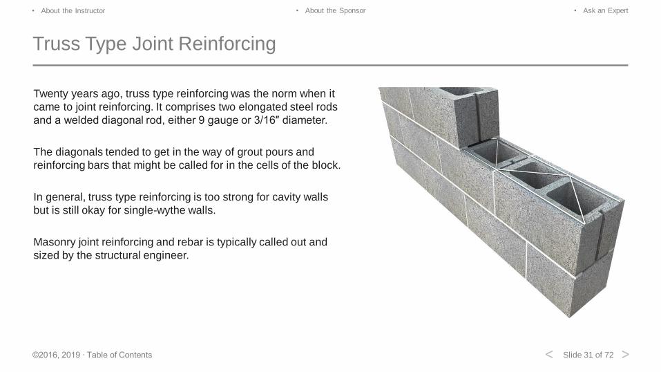
Truss Type Joint Reinforcing
Twenty years ago, truss type reinforcing was the norm when it
came to joint reinforcing. It comprises two elongated steel rods
and a welded diagonal rod, either 9 gauge or 3/16″ diameter.
The diagonals tended to get in the way of grout pours and
reinforcing bars that might be called for in the cells of the block.
In general, truss type reinforcing is too strong for cavity walls
but is still okay for single-wythe walls.
Masonry joint reinforcing and rebar is typically called out and
sized by the structural engineer.
Slide 32 of 72©2016, 2019 ∙ Table of Contents
• About the Instructor • About the Sponsor • Ask an Expert
< >
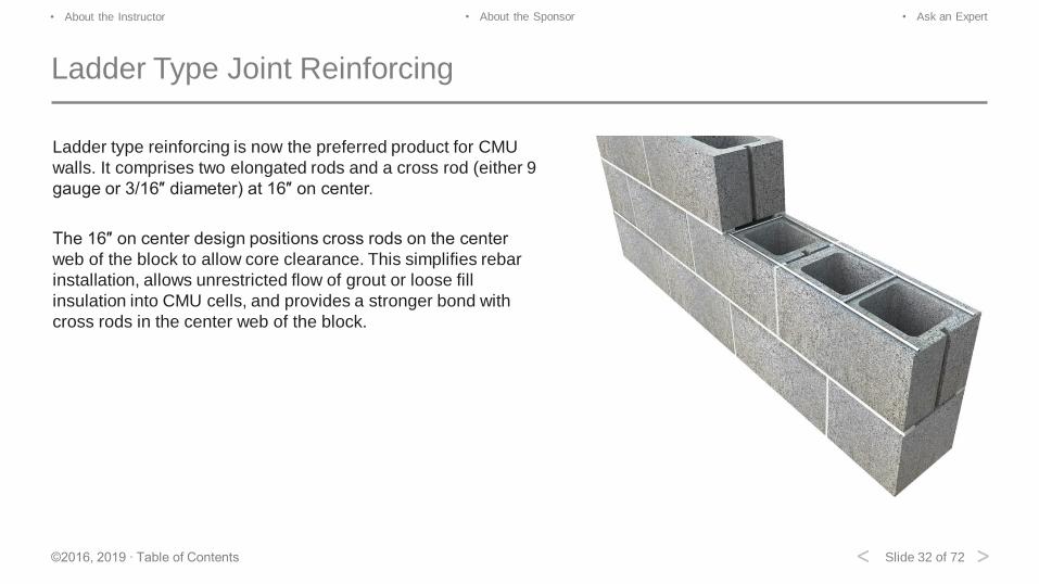
Ladder Type Joint Reinforcing
Ladder type reinforcing is now the preferred product for CMU
walls. It comprises two elongated rods and a cross rod (either 9
gauge or 3/16″ diameter) at 16″ on center.
The 16″ on center design positions cross rods on the center
web of the block to allow core clearance. This simplifies rebar
installation, allows unrestricted flow of grout or loose fill
insulation into CMU cells, and provides a stronger bond with
cross rods in the center web of the block.
Slide 33 of 72©2016, 2019 ∙ Table of Contents
• About the Instructor • About the Sponsor • Ask an Expert
< >
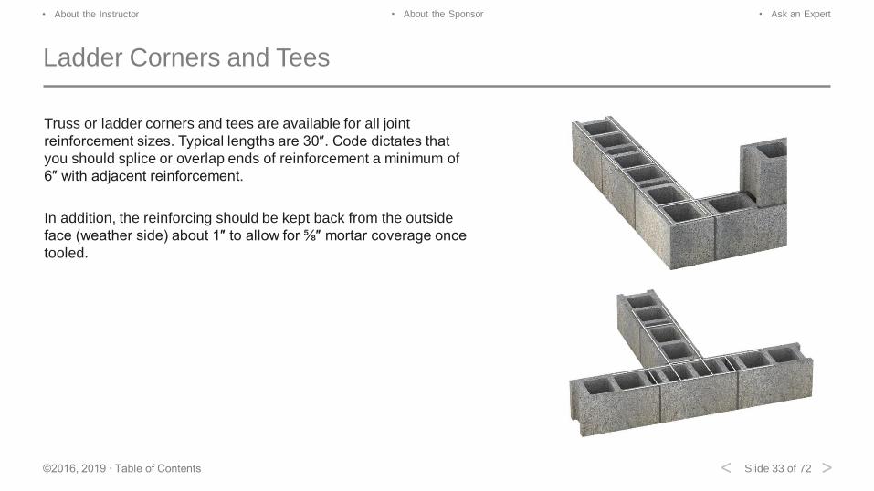
Ladder Corners and Tees
Truss or ladder corners and tees are available for all joint
reinforcement sizes. Typical lengths are 30″. Code dictates that
you should splice or overlap ends of reinforcement a minimum of
6″ with adjacent reinforcement.
In addition, the reinforcing should be kept back from the outside
face (weather side) about 1″ to allow for ⅝″ mortar coverage once
tooled.
Slide 34 of 72©2016, 2019 ∙ Table of Contents
• About the Instructor • About the Sponsor • Ask an Expert
< >
Functions of Joint Reinforcing
Joint reinforcing strengthens the mortar joint, which helps control shrinkage cracking. It bonds masonry wythes together in
composite and cavity walls. One-inch air space is required, but 2″ is recommended.
Joint reinforcing also allows loads to be transferred from the brick veneer to the stronger CMU or metal stud backup,
bonds intersecting walls, and increases the wall’s flexural strength.
Slide 35 of 72©2016, 2019 ∙ Table of Contents
• About the Instructor • About the Sponsor • Ask an Expert
< >
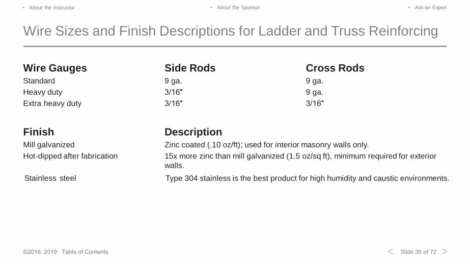
Wire Sizes and Finish Descriptions for Ladder and Truss Reinforcing
Wire Gauges Side Rods Cross RodsStandard 9 ga. 9 ga.
Heavy duty 3/16″ 9 ga.
Extra heavy duty 3/16″ 3/16″
Finish DescriptionMill galvanized Zinc coated (.10 oz/ft); used for interior masonry walls only.
Hot-dipped after fabrication 15x more zinc than mill galvanized (1.5 oz/sq ft), minimum required for exterior
walls.
Stainless steel Type 304 stainless is the best product for high humidity and caustic environments.
Slide 36 of 72©2016, 2019 ∙ Table of Contents
• About the Instructor • About the Sponsor • Ask an Expert
< >
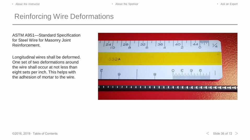
Reinforcing Wire Deformations
ASTM A951—Standard Specification
for Steel Wire for Masonry Joint
Reinforcement.
Longitudinal wires shall be deformed.
One set of two deformations around
the wire shall occur at not less than
eight sets per inch. This helps with
the adhesion of mortar to the wire.
Slide 37 of 72©2016, 2019 ∙ Table of Contents
• About the Instructor • About the Sponsor • Ask an Expert
< >
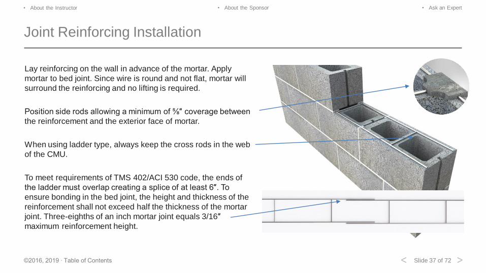
Joint Reinforcing Installation
Lay reinforcing on the wall in advance of the mortar. Apply
mortar to bed joint. Since wire is round and not flat, mortar will
surround the reinforcing and no lifting is required.
Position side rods allowing a minimum of ⅝″ coverage between
the reinforcement and the exterior face of mortar.
When using ladder type, always keep the cross rods in the web
of the CMU.
To meet requirements of TMS 402/ACI 530 code, the ends of
the ladder must overlap creating a splice of at least 6″. To
ensure bonding in the bed joint, the height and thickness of the
reinforcement shall not exceed half the thickness of the mortar
joint. Three-eighths of an inch mortar joint equals 3/16″
maximum reinforcement height.
Slide 38 of 72©2016, 2019 ∙ Table of Contents
• About the Instructor • About the Sponsor • Ask an Expert
< >
Review Question
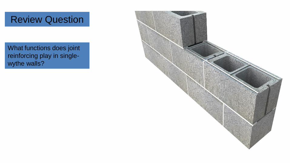
What functions does joint
reinforcing play in single-
wythe walls?
Slide 39 of 72©2016, 2019 ∙ Table of Contents
• About the Instructor • About the Sponsor • Ask an Expert
< >
Answer
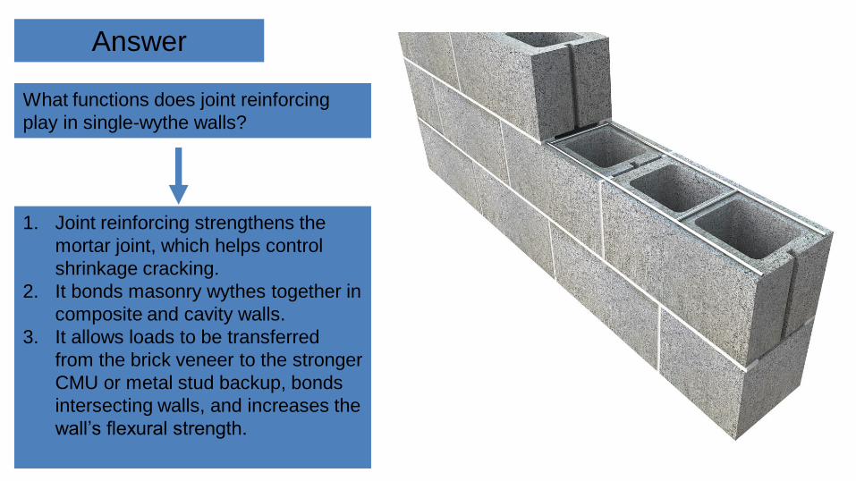
What functions does joint reinforcing
play in single-wythe walls?
1. Joint reinforcing strengthens the
mortar joint, which helps control
shrinkage cracking.
2. It bonds masonry wythes together in
composite and cavity walls.
3. It allows loads to be transferred
from the brick veneer to the stronger
CMU or metal stud backup, bonds
intersecting walls, and increases the
wall’s flexural strength.
Slide 40 of 72©2016, 2019 ∙ Table of Contents
• About the Instructor • About the Sponsor • Ask an Expert
< >
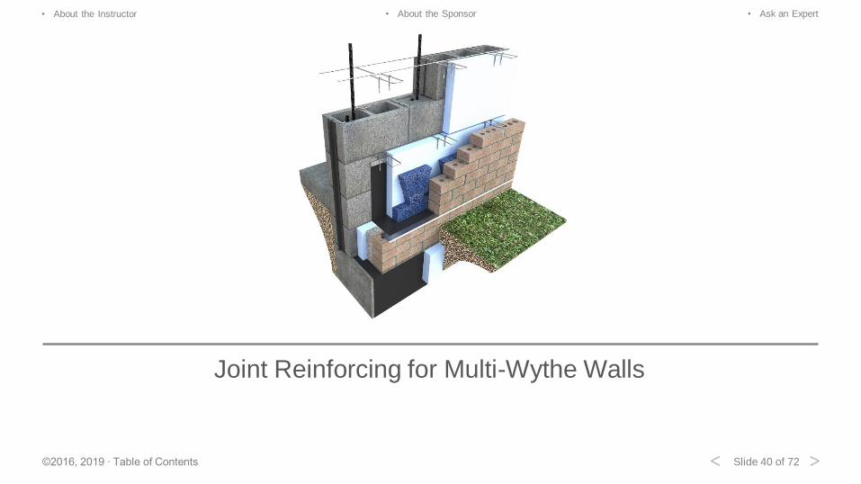
Joint Reinforcing for Multi-Wythe Walls
Slide 41 of 72©2016, 2019 ∙ Table of Contents
• About the Instructor • About the Sponsor • Ask an Expert
< >
Ladder Three-Wire, Four-Wire, and Fixed Tab
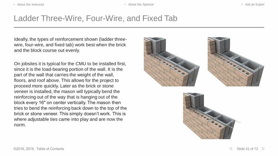
Ideally, the types of reinforcement shown (ladder three-
wire, four-wire, and fixed tab) work best when the brick
and the block course out evenly.
On jobsites it is typical for the CMU to be installed first,
since it is the load-bearing portion of the wall. It is the
part of the wall that carries the weight of the wall,
floors, and roof above. This allows for the project to
proceed more quickly. Later as the brick or stone
veneer is installed, the mason will typically bend the
reinforcing out of the way that is hanging out of the
block every 16″ on center vertically. The mason then
tries to bend the reinforcing back down to the top of the
brick or stone veneer. This simply doesn’t work. This is
where adjustable ties came into play and are now the
norm.
Slide 42 of 72©2016, 2019 ∙ Table of Contents
• About the Instructor • About the Sponsor • Ask an Expert
< >
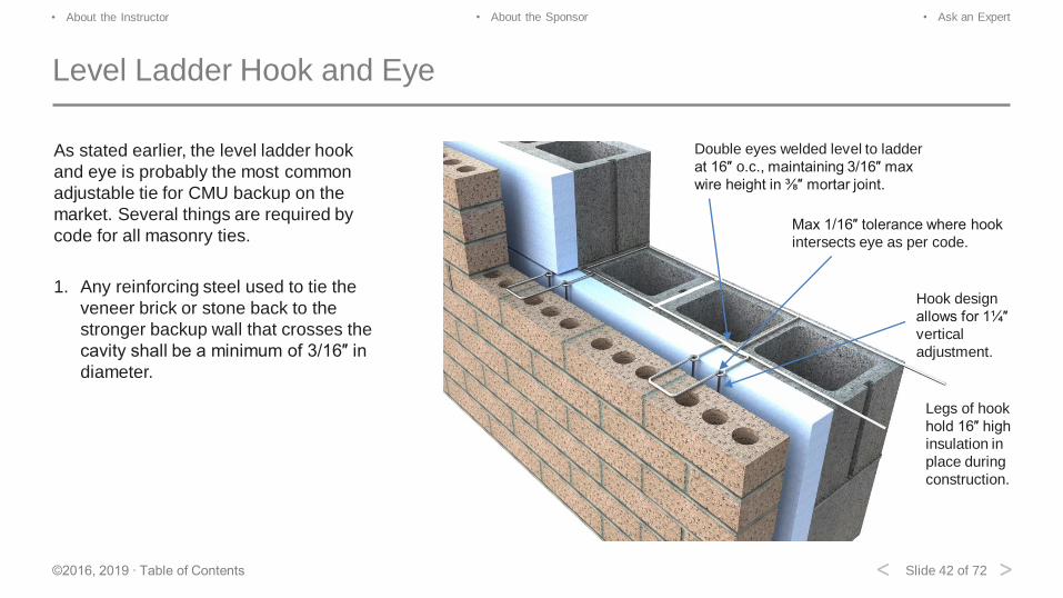
Level Ladder Hook and Eye
As stated earlier, the level ladder hook
and eye is probably the most common
adjustable tie for CMU backup on the
market. Several things are required by
code for all masonry ties.
1. Any reinforcing steel used to tie the
veneer brick or stone back to the
stronger backup wall that crosses the
cavity shall be a minimum of 3/16″ in
diameter.
Hook design
allows for 1¼″
vertical
adjustment.
Double eyes welded level to ladder
at 16″ o.c., maintaining 3/16″ max
wire height in ⅜″ mortar joint.
Max 1/16″ tolerance where hook
intersects eye as per code.
Legs of hook
hold 16″ high
insulation in
place during
construction.
Slide 43 of 72©2016, 2019 ∙ Table of Contents
• About the Instructor • About the Sponsor • Ask an Expert
< >
Level Ladder Hook and Eye
2. Since the brick or stone veneer is typically laid sometime after the CMU, the tie will have an adjustment of at least 1¼″
vertically to accommodate potential uneven coursing between the two wythes. At the end of the 1¼″, the tie should
have a bend or loop to discourage disengagement.
3. Where the 3/16″ diameter tie interacts with the 3/16″ diameter loops or pintle coming from the stronger backup wall,
no more than a 1/16″ tolerance is allowed. This minimizes excessive movement as the wind changes from a push/pull
load.
4. The hook should lie at least 1½″ onto the brick from the cavity side and have at least ⅝″ mortar coverage from the
weather side.
5. As per the Brick Industry Association, each tie should be able to withstand a minimum 100 lb load in either tension or
compression.
Slide 44 of 72©2016, 2019 ∙ Table of Contents
• About the Instructor • About the Sponsor • Ask an Expert
< >
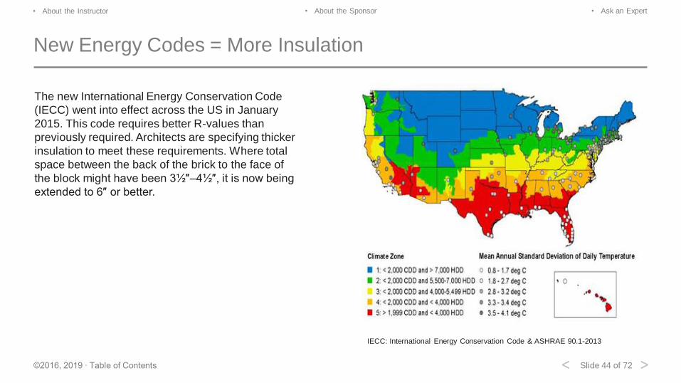
New Energy Codes = More Insulation
The new International Energy Conservation Code
(IECC) went into effect across the US in January
2015. This code requires better R-values than
previously required. Architects are specifying thicker
insulation to meet these requirements. Where total
space between the back of the brick to the face of
the block might have been 3½″–4½″, it is now being
extended to 6″ or better.
IECC: International Energy Conservation Code & ASHRAE 90.1-2013
Slide 45 of 72©2016, 2019 ∙ Table of Contents
• About the Instructor • About the Sponsor • Ask an Expert
< >
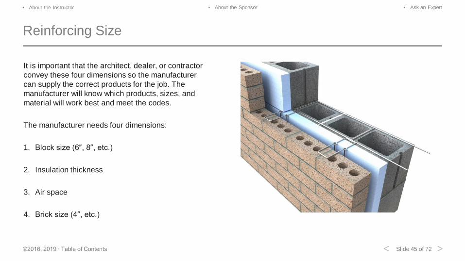
Reinforcing Size
It is important that the architect, dealer, or contractor
convey these four dimensions so the manufacturer
can supply the correct products for the job. The
manufacturer will know which products, sizes, and
material will work best and meet the codes.
The manufacturer needs four dimensions:
1. Block size (6″, 8″, etc.)
2. Insulation thickness
3. Air space
4. Brick size (4″, etc.)
Slide 46 of 72©2016, 2019 ∙ Table of Contents
• About the Instructor • About the Sponsor • Ask an Expert
< >
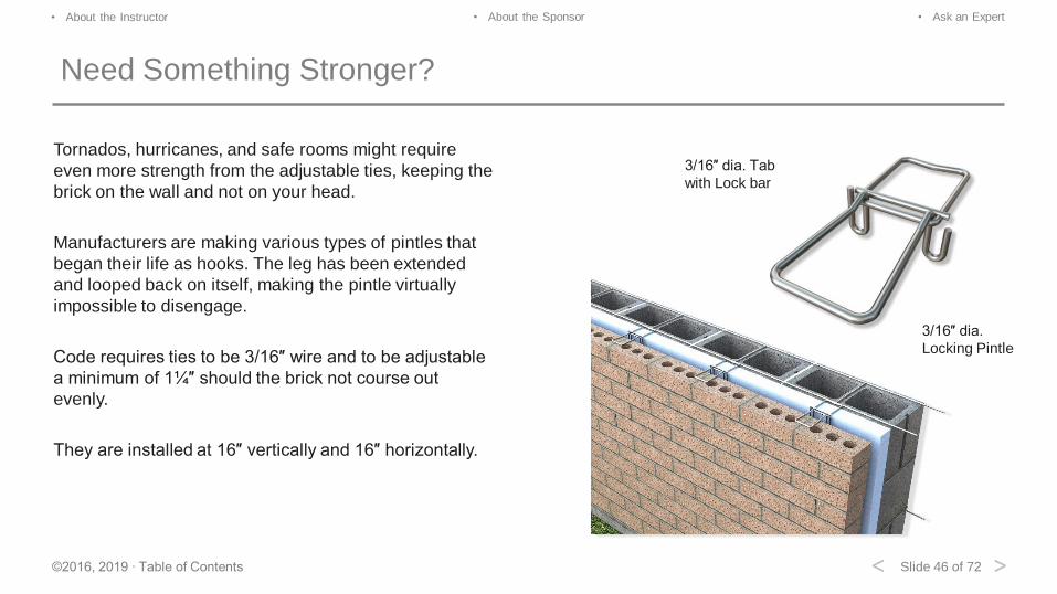
Need Something Stronger?
Tornados, hurricanes, and safe rooms might require
even more strength from the adjustable ties, keeping the
brick on the wall and not on your head.
Manufacturers are making various types of pintles that
began their life as hooks. The leg has been extended
and looped back on itself, making the pintle virtually
impossible to disengage.
Code requires ties to be 3/16″ wire and to be adjustable
a minimum of 1¼″ should the brick not course out
evenly.
They are installed at 16″ vertically and 16″ horizontally.
3/16″ dia. Tab
with Lock bar
3/16″ dia.
Locking Pintle
Slide 47 of 72©2016, 2019 ∙ Table of Contents
• About the Instructor • About the Sponsor • Ask an Expert
< >
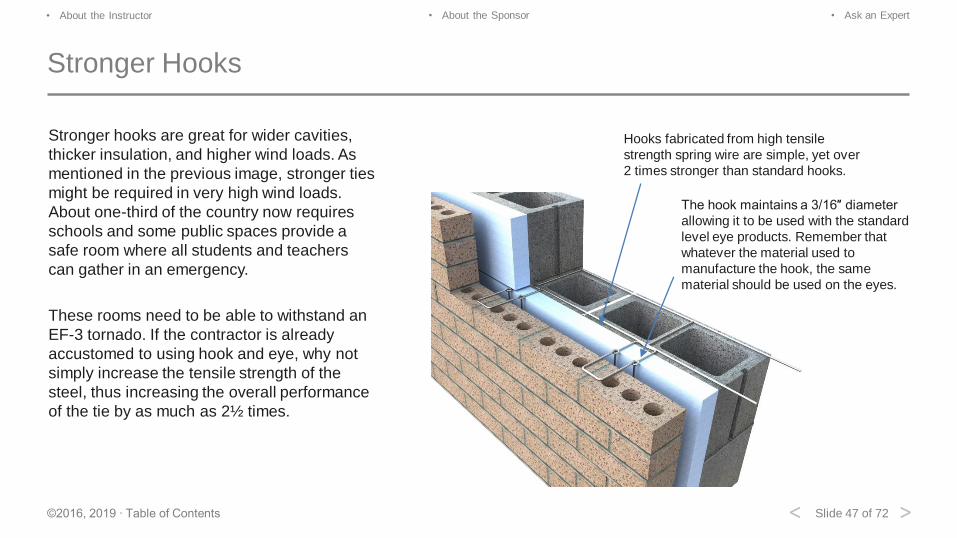
Stronger Hooks
Stronger hooks are great for wider cavities,
thicker insulation, and higher wind loads. As
mentioned in the previous image, stronger ties
might be required in very high wind loads.
About one-third of the country now requires
schools and some public spaces provide a
safe room where all students and teachers
can gather in an emergency.
These rooms need to be able to withstand an
EF-3 tornado. If the contractor is already
accustomed to using hook and eye, why not
simply increase the tensile strength of the
steel, thus increasing the overall performance
of the tie by as much as 2½ times.
The hook maintains a 3/16″ diameter
allowing it to be used with the standard
level eye products. Remember that
whatever the material used to
manufacture the hook, the same
material should be used on the eyes.
Hooks fabricated from high tensile
strength spring wire are simple, yet over
2 times stronger than standard hooks.
Slide 48 of 72©2016, 2019 ∙ Table of Contents
• About the Instructor • About the Sponsor • Ask an Expert
< >
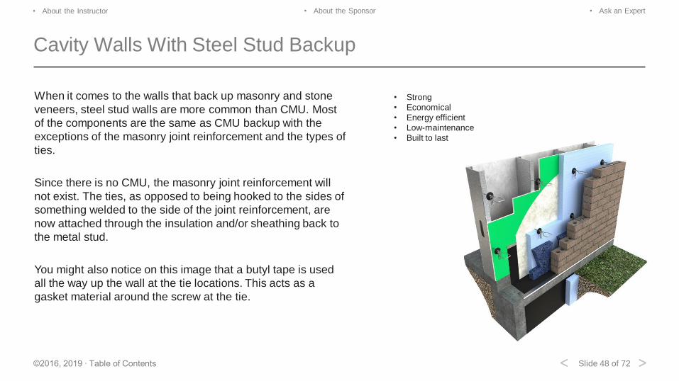
Cavity Walls With Steel Stud Backup
When it comes to the walls that back up masonry and stone
veneers, steel stud walls are more common than CMU. Most
of the components are the same as CMU backup with the
exceptions of the masonry joint reinforcement and the types of
ties.
Since there is no CMU, the masonry joint reinforcement will
not exist. The ties, as opposed to being hooked to the sides of
something welded to the side of the joint reinforcement, are
now attached through the insulation and/or sheathing back to
the metal stud.
You might also notice on this image that a butyl tape is used
all the way up the wall at the tie locations. This acts as a
gasket material around the screw at the tie.
• Strong
• Economical
• Energy efficient
• Low-maintenance
• Built to last
Slide 49 of 72©2016, 2019 ∙ Table of Contents
• About the Instructor • About the Sponsor • Ask an Expert
< >
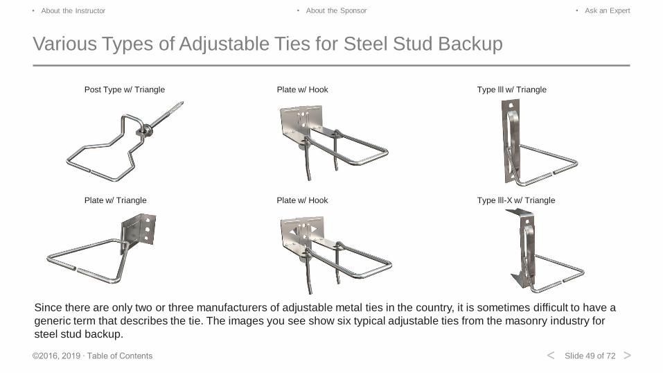
Various Types of Adjustable Ties for Steel Stud Backup
Post Type w/ Triangle Plate w/ Hook Type lll w/ Triangle
Plate w/ Triangle Plate w/ Hook Type lll-X w/ Triangle
Since there are only two or three manufacturers of adjustable metal ties in the country, it is sometimes difficult to have a
generic term that describes the tie. The images you see show six typical adjustable ties from the masonry industry for
steel stud backup.
Slide 50 of 72©2016, 2019 ∙ Table of Contents
• About the Instructor • About the Sponsor • Ask an Expert
< >
Various Types of Adjustable Ties for Steel Stud Backup
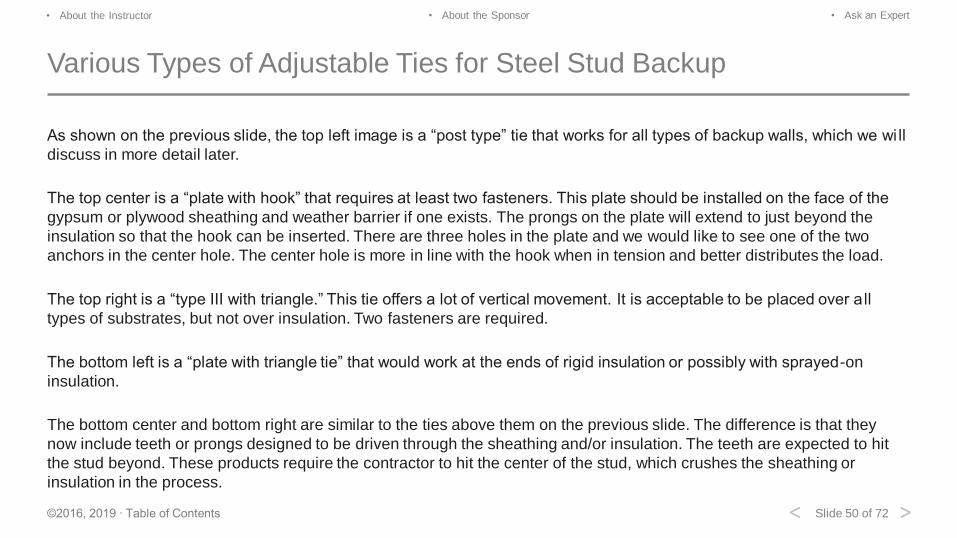
As shown on the previous slide, the top left image is a “post type” tie that works for all types of backup walls, which we wi ll
discuss in more detail later.
The top center is a “plate with hook” that requires at least two fasteners. This plate should be installed on the face of the
gypsum or plywood sheathing and weather barrier if one exists. The prongs on the plate will extend to just beyond the
insulation so that the hook can be inserted. There are three holes in the plate and we would like to see one of the two
anchors in the center hole. The center hole is more in line with the hook when in tension and better distributes the load.
The top right is a “type III with triangle.” This tie offers a lot of vertical movement. It is acceptable to be placed over a ll
types of substrates, but not over insulation. Two fasteners are required.
The bottom left is a “plate with triangle tie” that would work at the ends of rigid insulation or possibly with sprayed-on
insulation.
The bottom center and bottom right are similar to the ties above them on the previous slide. The difference is that they
now include teeth or prongs designed to be driven through the sheathing and/or insulation. The teeth are expected to hit
the stud beyond. These products require the contractor to hit the center of the stud, which crushes the sheathing or
insulation in the process.
Slide 51 of 72©2016, 2019 ∙ Table of Contents
• About the Instructor • About the Sponsor • Ask an Expert
< >
Adjustable Anchor and Tie Requirements
Anchors that connect the veneer to the backing must provide out-of-plane support, resisting tension and compression, but
allowing shear. Anchors must be embedded at least 1½″ into the brick veneer with a minimum mortar coverage of ⅝″ on
the outside face of the wall.
Maximum clearance between connecting parts of the tie shall be 1/16″. Adjustable anchors shall be detailed to prevent
disengagement. Pintles (double hooks) shall have at least two 3/16″ legs and shall have an offset not exceeding 1¼″.
Horizontal and vertical spacing shall not exceed 16″ o.c. Wall ties shall be without drips. Minimum air space shall be 1″ per
code, but 2″ is recommended by all industry associations.
Maximum void between steel framing and inside face of veneer is 6 ⅝″ by code, without any engineering or tie
calculations.
Maximum span for a wire tie in the cavity is 2″ when the cavity exceeds 4 ⅝″.
Slide 52 of 72©2016, 2019 ∙ Table of Contents
• About the Instructor • About the Sponsor • Ask an Expert
< >
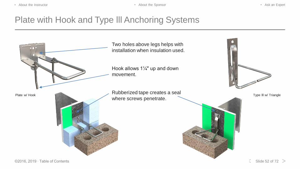
Plate with Hook and Type lll Anchoring Systems
Plate w/ Hook Type lll w/ Triangle
Two holes above legs helps with
installation when insulation used.
Hook allows 1¼″ up and down
movement.
Rubberized tape creates a seal
where screws penetrate.
Slide 53 of 72©2016, 2019 ∙ Table of Contents
• About the Instructor • About the Sponsor • Ask an Expert
< >
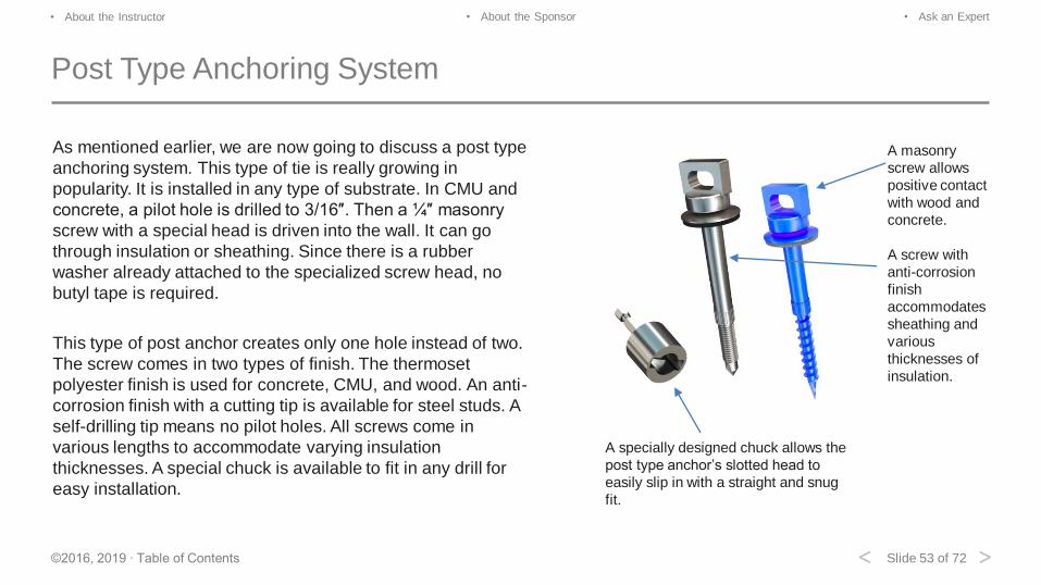
Post Type Anchoring System
As mentioned earlier, we are now going to discuss a post type
anchoring system. This type of tie is really growing in
popularity. It is installed in any type of substrate. In CMU and
concrete, a pilot hole is drilled to 3/16″. Then a ¼″ masonry
screw with a special head is driven into the wall. It can go
through insulation or sheathing. Since there is a rubber
washer already attached to the specialized screw head, no
butyl tape is required.
This type of post anchor creates only one hole instead of two.
The screw comes in two types of finish. The thermoset
polyester finish is used for concrete, CMU, and wood. An anti-
corrosion finish with a cutting tip is available for steel studs. A
self-drilling tip means no pilot holes. All screws come in
various lengths to accommodate varying insulation
thicknesses. A special chuck is available to fit in any drill for
easy installation.
A masonry
screw allows
positive contact
with wood and
concrete.
A screw with
anti-corrosion
finish
accommodates
sheathing and
various
thicknesses of
insulation.
A specially designed chuck allows the
post type anchor’s slotted head to
easily slip in with a straight and snug
fit.
Slide 54 of 72©2016, 2019 ∙ Table of Contents
• About the Instructor • About the Sponsor • Ask an Expert
< >
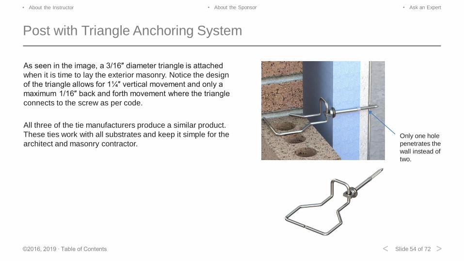
Post with Triangle Anchoring System
As seen in the image, a 3/16″ diameter triangle is attached
when it is time to lay the exterior masonry. Notice the design
of the triangle allows for 1¼″ vertical movement and only a
maximum 1/16″ back and forth movement where the triangle
connects to the screw as per code.
All three of the tie manufacturers produce a similar product.
These ties work with all substrates and keep it simple for the
architect and masonry contractor.Only one hole
penetrates the
wall instead of
two.
Slide 55 of 72©2016, 2019 ∙ Table of Contents
• About the Instructor • About the Sponsor • Ask an Expert
< >
Post with Triangle Anchoring System
Note that ties in masonry walls are considered by three sources to add no appreciable thermal conductance.
1. When the new International Energy Conservation Code (IECC) was adopted 1/1/2015, it stated, “the code does not
require a reduction in R-value calculation for masonry ties, fasteners, or anchors.”
2. The American Society of Heating, Refrigerating, and Air-Conditioning Engineers (ASHRAE) in their report, “Thermal
Performance of Building Envelope Details for Mid- and High-Rise Buildings” (5085243.01 MH 1365-RP July 6, 2011)
states that brick ties are an example of a clear field anomaly and “are considered not practical to account for on an
individual basis for whole building calculations.”
3. In August 2015, Architectural Testing, Inc. constructed two 8′ x 8′ brick veneer walls, one with ties and one with no ties
to gauge the thermal conductance of the ties. The walls were ½″ drywall, 16 gauge 2 x 6 metal studs, 16″ on center,
5/8″ gypsum sheathing, 2″ rigid insulation board, 1″ nominal air space, masonry ties at 16″ on center both vertically and
horizontal, 4″ nominal common red brick. In conclusion, “The wall assemblies, as tested, performed identically in terms
of U-Factor and R-Value” and “fasteners do not create any significant thermal bridging effects on this wall system.”
Slide 56 of 72©2016, 2019 ∙ Table of Contents
• About the Instructor • About the Sponsor • Ask an Expert
< >
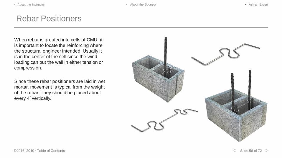
Rebar Positioners
When rebar is grouted into cells of CMU, it
is important to locate the reinforcing where
the structural engineer intended. Usually it
is in the center of the cell since the wind
loading can put the wall in either tension or
compression.
Since these rebar positioners are laid in wet
mortar, movement is typical from the weight
of the rebar. They should be placed about
every 4′ vertically.

Slide 57 of 72©2016, 2019 ∙ Table of Contents
• About the Instructor • About the Sponsor • Ask an Expert
< >
Recessed Rebar Positioner
A better solution for holding the rebar in place
is a recessed rebar positioner. This type of
rebar positioner is rigidly held in place by the
CMU and is not dependent on the wet mortar,
ensuring that you keep the rebar where the
structural engineer wants it. All rebar
positioners are available for both single and
double reinforcing bars plus the splice.
Installs 1¼″ deep instead of on top
of the block.
Does not interfere with ladder wire
reinforcement.
Design prevents any movement
during installation.
Code requires that rebar be kept in
center of block cell.
Slide 58 of 72©2016, 2019 ∙ Table of Contents
• About the Instructor • About the Sponsor • Ask an Expert
< >
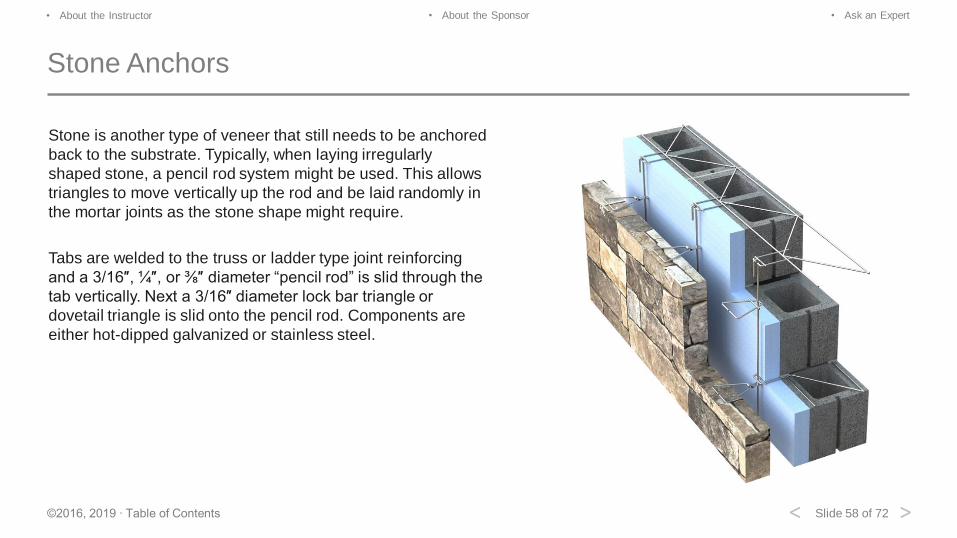
Stone Anchors
Stone is another type of veneer that still needs to be anchored
back to the substrate. Typically, when laying irregularly
shaped stone, a pencil rod system might be used. This allows
triangles to move vertically up the rod and be laid randomly in
the mortar joints as the stone shape might require.
Tabs are welded to the truss or ladder type joint reinforcing
and a 3/16″, ¼″, or ⅜″ diameter “pencil rod” is slid through the
tab vertically. Next a 3/16″ diameter lock bar triangle or
dovetail triangle is slid onto the pencil rod. Components are
either hot-dipped galvanized or stainless steel.
Slide 59 of 72©2016, 2019 ∙ Table of Contents
• About the Instructor • About the Sponsor • Ask an Expert
< >
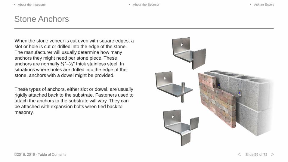
Stone Anchors
When the stone veneer is cut even with square edges, a
slot or hole is cut or drilled into the edge of the stone.
The manufacturer will usually determine how many
anchors they might need per stone piece. These
anchors are normally ⅛″–½″ thick stainless steel. In
situations where holes are drilled into the edge of the
stone, anchors with a dowel might be provided.
These types of anchors, either slot or dowel, are usually
rigidly attached back to the substrate. Fasteners used to
attach the anchors to the substrate will vary. They can
be attached with expansion bolts when tied back to
masonry.

Slide 60 of 72©2016, 2019 ∙ Table of Contents
• About the Instructor • About the Sponsor • Ask an Expert
< >
Review Question
Match the images on the
right with the correct label
on the left.
Ladder three-wire
Four-wire
Fixed tab
Slide 61 of 72©2016, 2019 ∙ Table of Contents
• About the Instructor • About the Sponsor • Ask an Expert
< >
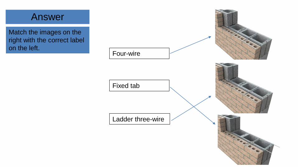
Answer
Match the images on the
right with the correct label
on the left.
Ladder three-wire
Four-wire
Fixed tab
Slide 62 of 72©2016, 2019 ∙ Table of Contents
• About the Instructor • About the Sponsor • Ask an Expert
< >
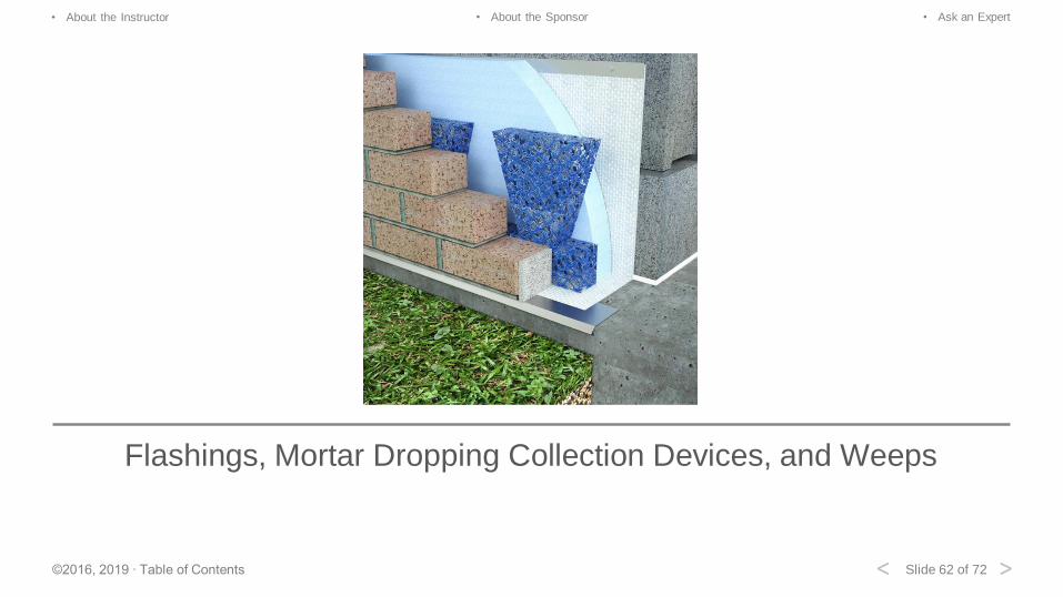
Flashings, Mortar Dropping Collection Devices, and Weeps
Slide 63 of 72©2016, 2019 ∙ Table of Contents
• About the Instructor • About the Sponsor • Ask an Expert
< >
Basic Types of Flashing
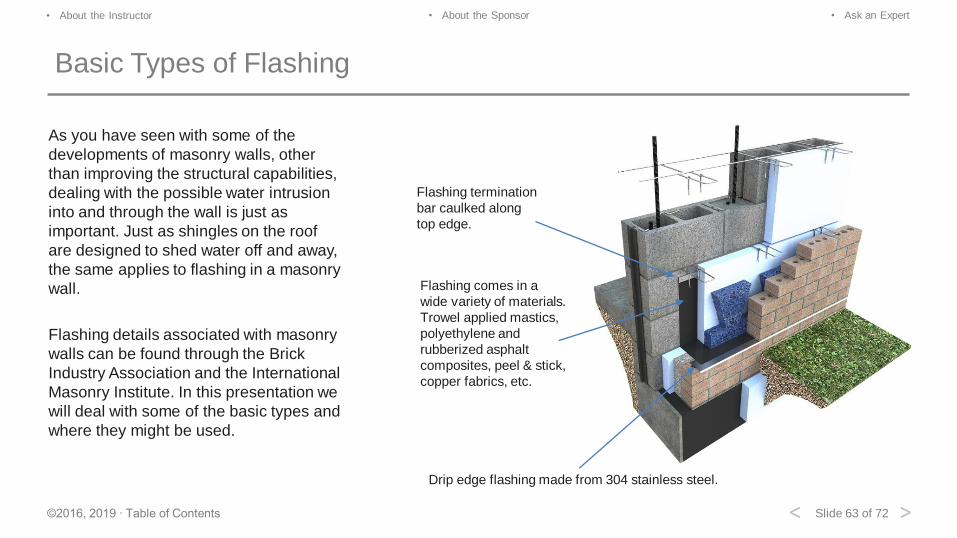
As you have seen with some of the
developments of masonry walls, other
than improving the structural capabilities,
dealing with the possible water intrusion
into and through the wall is just as
important. Just as shingles on the roof
are designed to shed water off and away,
the same applies to flashing in a masonry
wall.
Flashing details associated with masonry
walls can be found through the Brick
Industry Association and the International
Masonry Institute. In this presentation we
will deal with some of the basic types and
where they might be used.
Flashing termination
bar caulked along
top edge.
Drip edge flashing made from 304 stainless steel.
Flashing comes in a
wide variety of materials.
Trowel applied mastics,
polyethylene and
rubberized asphalt
composites, peel & stick,
copper fabrics, etc.
Slide 64 of 72©2016, 2019 ∙ Table of Contents
• About the Instructor • About the Sponsor • Ask an Expert
< >
Types of Flashing
PVC: Non-reinforced polyvinyl chloride sheet:
Use in milder climates because it can become rigid and brittle under severe freeze-thaw conditions.
Use on concealed foundation walls, under slab, and as thru-wall flashing.
Polyethylene/Rubberized Asphalt:
Can be used in all climates, is peel and stick. Sticks to concrete, steel, wood, and gypsum.
Use for thru-wall, foundation sill, base, parapet head and sill.
Polyester Scrim/Thermoplastic:
Many companies use a thermoplastic product, a ketone ethylene ester (KEE). Used with a polyester scrim and butyl
adhesive, it works very well.
For use in all climates, is peel and stick. Resists oil and most chemicals, will not drool, no UV degradation, and is
considered the best non-metallic peel and stick.
Slide 65 of 72©2016, 2019 ∙ Table of Contents
• About the Instructor • About the Sponsor • Ask an Expert
< >
Types of Flashing
Copper Fabric: Copper sheet laminated between blended asphalt and glass fabric:
3, 5, and 7 oz copper. Excellent for thru-wall and surface applications with no drool.
Copper/Rubberized Asphalt:
3 oz copper sheet with polyester film on one side and rubberized asphalt on the other. It is highly adhesive. Rubberized
asphalt has a greater longevity compared to standard asphalt.
Please remember the test password FLASHING. You will be required to enter it in order to proceed with the online test.
Slide 66 of 72©2016, 2019 ∙ Table of Contents
• About the Instructor • About the Sponsor • Ask an Expert
< >
Mortar Droppings Collection Device and Weeps (MDCD)
The basic idea is to allow any water that might get through the exterior veneer to be stopped by the flashing, fall, or run
down the cavity and be weeped out of the cavity through weeps at 24″ on center horizontally. In general, the MDCD
should be in the bottom of the cavity to catch any mortar that might fall into the cavity while the exterior brick wall is laid.
The MDCD keeps the weeps clear. Weeps can come in many types. When selecting weeps, consider the following.
1. Weeps should allow water to exit the cavity.
2. Weeps should stop insects from entering the cavity from outside.
3. Recently there has been a push by the design community to add more weeps in an effort to increase the airflow or
convection of air in the cavity. Weeps or Vents should be spaced 24″ horizontally to meet code requirements. Adding
weeps under windows and at the tops of walls is also a good idea.
4. Select weeps that offer more airflow by their design.
5. Selecting weeps that more closely match the mortar color is usually a good idea for aesthetic reasons.
Slide 67 of 72©2016, 2019 ∙ Table of Contents
• About the Instructor • About the Sponsor • Ask an Expert
< >
Mortar Droppings Collection Device (MDCD)
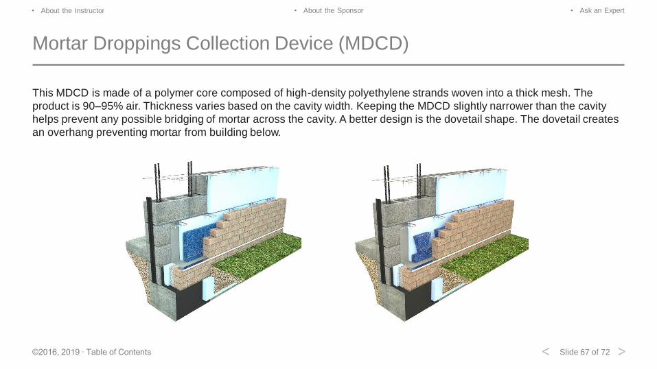
This MDCD is made of a polymer core composed of high-density polyethylene strands woven into a thick mesh. The
product is 90–95% air. Thickness varies based on the cavity width. Keeping the MDCD slightly narrower than the cavity
helps prevent any possible bridging of mortar across the cavity. A better design is the dovetail shape. The dovetail creates
an overhang preventing mortar from building below.
Slide 68 of 72©2016, 2019 ∙ Table of Contents
• About the Instructor • About the Sponsor • Ask an Expert
< >
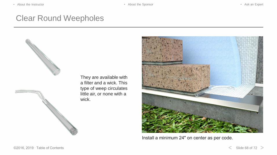
Clear Round Weepholes
They are available with
a filter and a wick. This
type of weep circulates
little air, or none with a
wick.
Install a minimum 24″ on center as per code.
Slide 69 of 72©2016, 2019 ∙ Table of Contents
• About the Instructor • About the Sponsor • Ask an Expert
< >
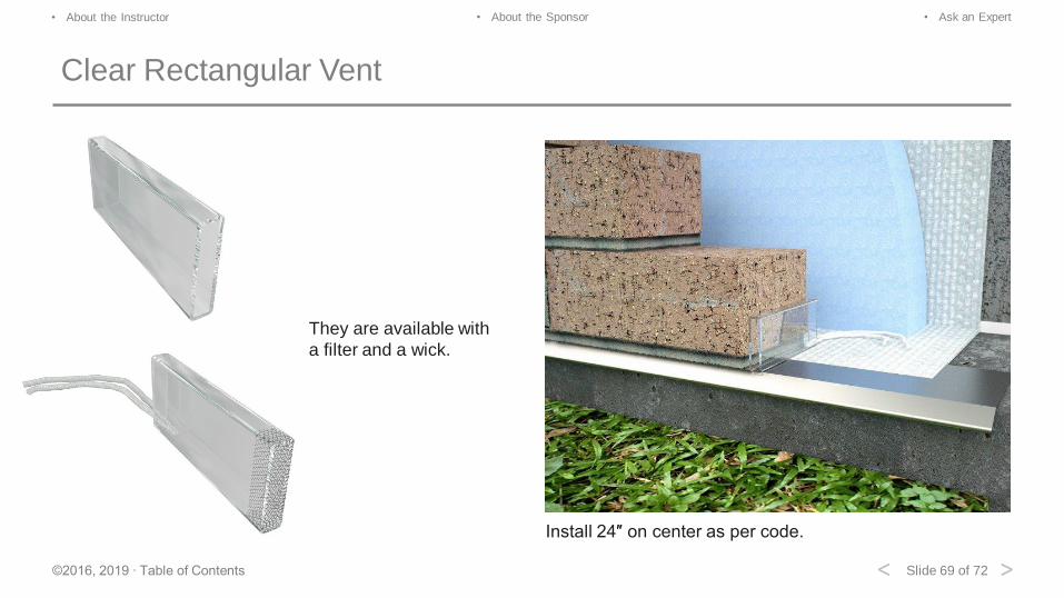
Clear Rectangular Vent
They are available with
a filter and a wick.
Install 24″ on center as per code.
Slide 70 of 72©2016, 2019 ∙ Table of Contents
• About the Instructor • About the Sponsor • Ask an Expert
< >
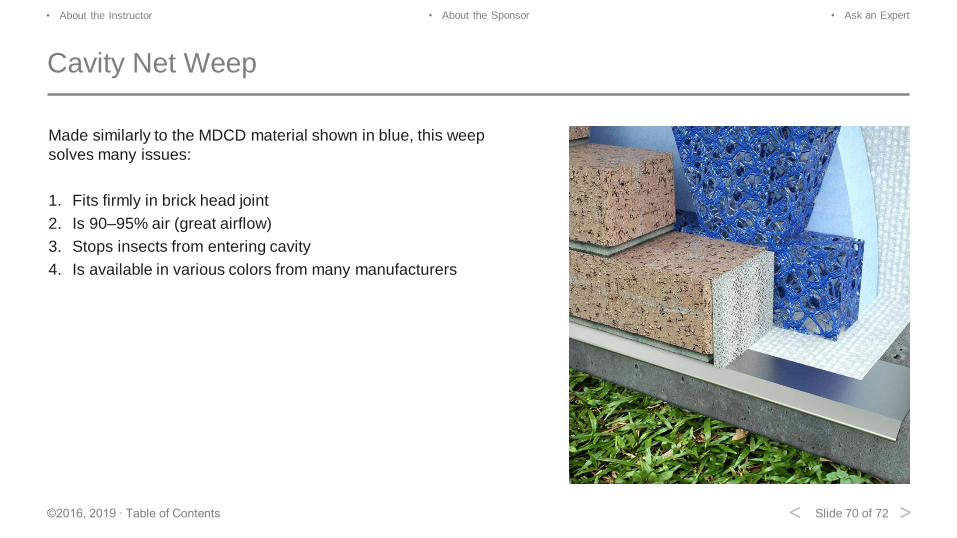
Cavity Net Weep
Made similarly to the MDCD material shown in blue, this weep
solves many issues:
1. Fits firmly in brick head joint
2. Is 90–95% air (great airflow)
3. Stops insects from entering cavity
4. Is available in various colors from many manufacturers
Slide 71 of 72©2016, 2019 ∙ Table of Contents
• About the Instructor • About the Sponsor • Ask an Expert
< >
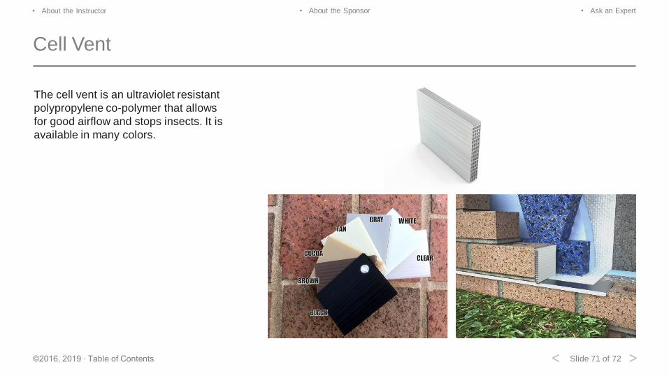
Cell Vent
The cell vent is an ultraviolet resistant
polypropylene co-polymer that allows
for good airflow and stops insects. It is
available in many colors.
Slide 72 of 72©2016, 2019 ∙ Table of Contents
• About the Instructor • About the Sponsor • Ask an Expert
< >
Conclusion
If you desire AIA/CES, state licensing or CE credits for another
organization, please click on the button to commence your online test. A
score of 80% or better will allow you to print your Certificate of
Completion; you may also go to your AEC Daily Transcript to see your
completed courses and certificates.
For additional knowledge and post-seminar assistance, click on the Ask
an Expert link.
If you have colleagues that might benefit from this seminar, please let
them know. Feel free to revisit the AEC Daily website to download
additional programs.
©2016, 2019 Wire-Bond. The material contained in this course was researched,
assembled, and produced by Wire-Bond and remains its property. Questions or
concerns about the content of this course should be directed to the program
instructor. This multimedia product is the copyright of AEC Daily.
Questions? Ask an Expert – click here
Exit
Click Here to Take the Test
MORE
powered by

![Sponsorship & Trade Display Proposal - RESA · [2] Contents 3 Event Overview 4 About RESA 5 Venue & Date 6 Gold Sponsor Opportunities 7 Silver Sponsor Opportunities 8 Bronze Sponsor](https://img.pdfslide.net/doc/110x75/5e12206cc5a1b32d1575fb40/sponsorship-trade-display-proposal-resa-2-contents-3-event-overview-4.jpg)