Embed Size (px)
Citation preview

PRIMERGY TX300 S4 Configuration Sheets
D Design Sheet of the RAID Configuration Use this form to record the definitions of the disk groups (or the physical packs) and the logical drives in the RAID configuration (array configuration).
E Design Sheet Use this form to record the software settings.
F Accident Sheet Use this form to record any failures that occur in your server.
A Configuration Sheets of Hardware Use this form to record the hardware configuration and various settings of your server.
B Configuration Sheets of BIOS Setup Utility Parameters Use this form to record the settings of the BIOS Setup Utility.
C Configuration Sheets of Remote Management Controller's Web Interface Use this form to record the settings of the Remote Management Controller Web interface.
About this manual
1

The following expressions and abbreviations are used to describe the product names used in this manual.
Product names
PRIMERGY TX300 S4 This server or the server
Microsoft® Windows Server® 2003 R2, Standard Edition Windows Server 2003 R2, Standard Edition
Windows 2003
Microsoft® Windows Server® 2003 R2, Enterprise Edition Windows Server 2003 R2, Enterprise Edition
Microsoft® Windows Server® 2003 , Enterprise Edition Windows Server 2003 , Enterprise Edition
Microsoft® Windows Server® 2003, Standard Edition Windows Server 2003, Standard Edition
Microsoft® Windows Server® 2003 R2, Standard x64 Edition Windows Server 2003 R2, Standard x64 Edition
Microsoft® Windows Server® 2003 R2 , Enterprise x64 Edition Windows Server 2003 R2, Enterprise x64 Edition
Microsoft® Windows Server® 2003, Standard x64 Edition Windows Server 2003, Standard x64 Edition
Microsoft® Windows Server® 2003 , Enterprise x64 Edition Windows Server 2003 , Enterprise x64 Edition
Microsoft® Windows Server® 2003 Service Pack SP
■Trademarks
Microsoft, Windows, MS, Windows Server are registered trademarks of the Microsoft Corporation in the USA and other
countries.
Intel, Xeon are registered trademarks or trademarks of Intel Corporation or its subsidiaries in the USA and other countries.
All other hardware and software names used are trademarks or registered trademarks of their respective manufacturers.
Other product names are copyrights of their respective manufacturers.
Copyright FUJITSU LIMITED 2008
Expressions and abbreviations
Product Names
2

PRIMERGY TX300 S4 Configuration Sheets
A Configuration Sheets of Hardware ・・・・・・・・・・・・・・・・・・・・・・・・・・・・・・ 4
B Configuration Sheets of BIOS Setup Utility Parameters ・・・・・・・・・・・・ 9
B.1 Parameters in the Main Menu ・・・・・・・・・・・・・・・・・・・・・・・・・・・・・・・・・・・・・・・・・・・ 9
B.2 Parameters in the Advanced Menu ・・・・・・・・・・・・・・・・・・・・・・・・・・・・・・・・・・・・・・・ 10
B.3 Parameters in the Security Menu ・・・・・・・・・・・・・・・・・・・・・・・・・・・・・・・・・・・・・・・・ 14
B.4 Parameters in the Server Menu ・・・・・・・・・・・・・・・・・・・・・・・・・・・・・・・・・・・・・・・・・・ 15
Interface ・・・・・・・・・・・・・・・・・・・・・・・・・・・・・・・・・・・・・・・・・・・・・・・・・・ 17
C.1 Parameters in the iRMC S2 ・・・・・・・・・・・・・・・・・・・・・・・・・・・・・・・・・・・・・・・・・・・・・ 17
C.2 Parameters in the Power Management ・・・・・・・・・・・・・・・・・・・・・・・・・・・・・・・・・・・・ 18
C.3 Parameters in the Power Consumption ・・・・・・・・・・・・・・・・・・・・・・・・・・・・・・・・・・・ 19
C.4 Parameters in the Fans ・・・・・・・・・・・・・・・・・・・・・・・・・・・・・・・・・・・・・・・・・・・・・・・・ 20
C.5 Parameters in the Temperature ・・・・・・・・・・・・・・・・・・・・・・・・・・・・・・・・・・・・・・・・・ 20
C.6 Parameters in the System Event Log ・・・・・・・・・・・・・・・・・・・・・・・・・・・・・・・・・・・・・ 21
C.7 Parameters in the Server Management Information ・・・・・・・・・・・・・・・・・・・・・・・・・・ 21
C.8 Parameters in the Network Settings ・・・・・・・・・・・・・・・・・・・・・・・・・・・・・・・・・・・・・・ 22
C.9 Parameters in the SNMP Trap Alerting ・・・・・・・・・・・・・・・・・・・・・・・・・・・・・・・・・・・・ 23
C.10 Parameters in the Email Alerting ・・・・・・・・・・・・・・・・・・・・・・・・・・・・・・・・・・・・・・・・ 23
C.11 Parameters in the User Management ・・・・・・・・・・・・・・・・・・・・・・・・・・・・・・・・・・・・ 24
C.12 Parameters in the LDAP Configuration ・・・・・・・・・・・・・・・・・・・・・・・・・・・・・・・・・・・ 27
C.13 Parameters in the BIOS Text Console ・・・・・・・・・・・・・・・・・・・・・・・・・・・・・・・・・・・ 27
C.14 Parameters in the Advanced Video Redirection ・・・・・・・・・・・・・・・・・・・・・・・・・・・・ 27
D Design Sheet of the RAID Configuration ・・・・・・・・・・・・・・・・・・・・・・・・ 28
D.1 For RAID 5/6 SAS based on LSI MegaRAID ・・・・・・・・・・・・・・・・・・・・・・・・・・・・・・・・ 28
D.2 For Integrated Mirroring SAS ・・・・・・・・・・・・・・・・・・・・・・・・・・・・・・・・・・・・・・・・・・・・ 31
D.3 For MegaRAID SAS 8344ELP ・・・・・・・・・・・・・・・・・・・・・・・・・・・・・・・・・・・・・・・・・・・ 33
E Design Sheet ・・・・・・・・・・・・・・・・・・・・・・・・・・・・・・・・・・・・・・・・・・・・・・・ 33
E.1 RAID/Disk Wizard ・・・・・・・・・・・・・・・・・・・・・・・・・・・・・・・・・・・・・・・・・・・・・・・・・・・・・ 33
E.2 OS Wizard (Windows 2003 Install Wizard) ・・・・・・・・・・・・・・・・・・・・・・・・・・・・・・・・・・ 34
E.3 Application Wizard ・・・・・・・・・・・・・・・・・・・・・・・・・・・・・・・・・・・・・・・・・・・・・・・・・・・・・ 39
F Accident Sheet ・・・・・・・・・・・・・・・・・・・・・・・・・・・・・・・・・・・・・・・・・・・・・ 40
C Configuration Sheets of Remote Management Controller's Web
Contents
3

A Configuration Sheets of Hardware
Use this form to record the hardware configuration and various settings of your server.Put a check mark in parentheses of your server settings.If you use the new supported product of this server which is not mentioned here, please note the information on the empty space.
■Internal hard disk unit●SAS model・3.5-inch SAS HDD Internal Options
Installed positionBay 1 ( ) 73.4 GB ( ) 146.8 GB ( ) 300 GBBay 2 ( ) 73.4 GB ( ) 146.8 GB ( ) 300 GBBay 3 ( ) 73.4 GB ( ) 146.8 GB ( ) 300 GBBay 4 ( ) 73.4 GB ( ) 146.8 GB ( ) 300 GBBay 5 ( ) 73.4 GB ( ) 146.8 GB ( ) 300 GBBay 6 ( ) 73.4 GB ( ) 146.8 GB ( ) 300 GB
・2.5-inch SAS HDD Internal OptionsInstalled position
Bay 1Bay 2Bay 3Bay 4Bay 5Bay 6Bay 7Bay 8Bay 9Bay 10Bay 11Bay 12Bay 13 *Bay 14 *Bay 15 *Bay 16 *Bay 17 *Bay 18 *Bay 19 *Bay 20 *
*:When using the hard disk unit bay conversion kit.(PG-BC104)
●SATA model・3.5-inch SATA HDD Internal Options
Installed positionBay 1 ( ) 80 GB ( ) 160 GB ( ) 500 GBBay 2 ( ) 80 GB ( ) 160 GB ( ) 500 GBBay 3 ( ) 80 GB ( ) 160 GB ( ) 500 GBBay 4 ( ) 80 GB ( ) 160 GB ( ) 500 GBBay 5 ( ) 80 GB ( ) 160 GB ( ) 500 GBBay 6 ( ) 80 GB ( ) 160 GB ( ) 500 GB
Installation 3.5 inch internal option
Installation 3.5 inch internal option
Installation 2.5 inch internal option( ) 73.4 GB [10Krpm] ( ) 73.4 GB [15Krpm] ( ) 146.8 GB( ) 73.4 GB [10Krpm] ( ) 73.4 GB [15Krpm] ( ) 146.8 GB( ) 73.4 GB [10Krpm] ( ) 73.4 GB [15Krpm] ( ) 146.8 GB( ) 73.4 GB [10Krpm] ( ) 73.4 GB [15Krpm] ( ) 146.8 GB( ) 73.4 GB [10Krpm] ( ) 73.4 GB [15Krpm] ( ) 146.8 GB( ) 73.4 GB [10Krpm] ( ) 73.4 GB [15Krpm] ( ) 146.8 GB( ) 73.4 GB [10Krpm] ( ) 73.4 GB [15Krpm] ( ) 146.8 GB( ) 73.4 GB [10Krpm] ( ) 73.4 GB [15Krpm] ( ) 146.8 GB( ) 73.4 GB [10Krpm] ( ) 73.4 GB [15Krpm] ( ) 146.8 GB( ) 73.4 GB [10Krpm] ( ) 73.4 GB [15Krpm] ( ) 146.8 GB( ) 73.4 GB [10Krpm] ( ) 73.4 GB [15Krpm] ( ) 146.8 GB( ) 73.4 GB [10Krpm] ( ) 73.4 GB [15Krpm] ( ) 146.8 GB( ) 73.4 GB [10Krpm] ( ) 73.4 GB [15Krpm] ( ) 146.8 GB( ) 73.4 GB [10Krpm] ( ) 73.4 GB [15Krpm] ( ) 146.8 GB( ) 73.4 GB [10Krpm] ( ) 73.4 GB [15Krpm] ( ) 146.8 GB
( ) 73.4 GB [10Krpm] ( ) 73.4 GB [15Krpm] ( ) 146.8 GB
( ) 73.4 GB [10Krpm] ( ) 73.4 GB [15Krpm] ( ) 146.8 GB( ) 73.4 GB [10Krpm] ( ) 73.4 GB [15Krpm] ( ) 146.8 GB( ) 73.4 GB [10Krpm] ( ) 73.4 GB [15Krpm] ( ) 146.8 GB( ) 73.4 GB [10Krpm] ( ) 73.4 GB [15Krpm] ( ) 146.8 GB
A Configuration Sheets of Hardware
4

PRIMERGY TX300 S4 Configuration Sheets
■5-inch Internal Options
Installed position Installation 3.5 inch internal option SCSI ID
( ) Internal hard disk unit bay conversion kit(PG-BC104)
■3.5-inch HDD model RAM modules
Installation slot Installation RAM module
( ) 1 GB ( ) 2 GB
( ) 4 GB ( ) 1 GB ( ) 2 GB
( ) 4 GB ( ) 1 GB ( ) 2 GB
( ) 4 GB ( ) 1 GB ( ) 2 GB
( ) 4 GB ( ) 1 GB ( ) 2 GB
( ) 4 GB ( ) 1 GB ( ) 2 GB
( ) 4 GB ( ) 1 GB ( ) 2 GB
( ) 4 GB ( ) 1 GB ( ) 2 GB
( ) 4 GB
-
( ) Internal LTO4 unit(PG-LT401)
6
Bay 3
( ) Internal LTO2 unit(PG-LT201)
( ) Internal LTO3 unit(PG-LT302)
( ) Internal LTO1 unit(PG-LT102)
( ) Internal DAT72 unit(PG-DT504)
-
Slot 1C/1D
Slot 2C/2D
Slot 3C/3D
Bay 1
Both bay 2 and bay 3
6
6
-
6
(Normal Installation) Internal DVD-ROM unit(Normal Installation) Floppy disk drive
Slot 4C/4D
Slot 1A/1B
Slot 2A/2B
Slot 3A/3B
Slot 4A/4B
Bay 2( ) Internal data cartridge drive unit(PG-RD102)
5

A Configuration Sheets of Hardware
■2.5-inch HDD model RAM modules
Installation slot Installation RAM module
( ) 1 GB ( ) 2 GB( ) 4 GB ( ) 8 GB
( ) 1 GB ( ) 2 GB( ) 4 GB ( ) 8 GB
( ) 1 GB ( ) 2 GB( ) 4 GB ( ) 8 GB
( ) 1 GB ( ) 2 GB( ) 4 GB ( ) 8 GB
( ) 1 GB ( ) 2 GB( ) 4 GB ( ) 8 GB
( ) 1 GB ( ) 2 GB( ) 4 GB ( ) 8 GB
( ) 1 GB ( ) 2 GB( ) 4 GB ( ) 8 GB
( ) 1 GB ( ) 2 GB( ) 4 GB ( ) 8 GB
■CPU
( ) CPU socket 1 ( ) CPU socket 2
( ) CPU socket 1 ( ) CPU socket 2
( ) CPU socket 1 ( ) CPU socket 2
( ) CPU socket 1 ( ) CPU socket 2
( ) CPU socket 1 ( ) CPU socket 2
( ) CPU socket 1 ( ) CPU socket 2
( ) CPU socket 1 ( ) CPU socket 2
( ) CPU socket 1 ( ) CPU socket 2
Same CPU must be installed in CPU socket 1 and CPU socket 2.
Slot 1A/1B
Slot 2A/2B
Slot 3A/3B
Slot 4A/4B
Slot 1C/1D
Slot 2C/2D
Slot 3C/3D
Slot 4C/4D
( ) Xeon Processor E5420/12MB (FSB1333MHz)
( ) Xeon Processor X5460/12MB (FSB1333MHz)
Installed positionInstallation CPU
( ) Xeon Processor E5205/6MB (FSB1066MHz)
( ) Xeon Processor X5260/6MB (FSB1333MHz)
( ) Xeon Processor E5405/12MB (FSB1333MHz)
( ) Xeon Processor X5270/6MB (FSB1333MHz)
( ) Xeon Processor X5470/12MB (FSB1333MHz)
6

PRIMERGY TX300 S4 Configuration Sheets
■PCI card
●3.5-inch SAS HDD model
1 2 3 4 5 6 7
( ) - - - - - -
( ) - - - - - -
( ) - - - - - -
- ( ) - - - - -
- ( ) ( ) - - - -
- ( ) ( ) - ( ) ( ) -
- - - - ( ) ( ) -
- - - - ( ) ( ) -
- ( ) ( ) - ( ) ( ) -
- ( ) ( ) - ( ) ( ) ( )
- ( ) ( ) - ( ) ( ) ( )
- ( ) ( ) - ( ) ( ) ( )
- - - ( ) - - -
- - - ( ) - - -
- - - ( ) - - -
- - - ( ) - - -
●2.5-inch SAS HDD model
1 2 3 4 5 6 7( ) - - - - - -
( ) ( ) - - - - -
( ) ( ) - - - - -
- ( ) - - - - -
- ( ) ( ) - ( ) - -
- ( ) ( ) - ( ) ( ) -
- - - - ( ) ( ) -
- - - - ( ) ( ) -
- ( ) ( ) - ( ) ( ) -
- ( ) ( ) - ( ) ( ) ( )
- ( ) ( ) - ( ) ( ) ( )
- ( ) ( ) - ( ) ( ) ( )
- - - ( ) - - -
- - - ( ) - - -
- - - ( ) - - -
- - - ( ) - - -
PCI slot location
-:Indicates that this item cannot be installed.
LAN card (PG-1892)
LAN card (PG-1853)
LAN card (PG-1882)
Fiber Channel card (PG-FC202)
LAN card (PG-1863)
Expansion card (Product ID)
LAN card (PG-2861)
SAS array controller card or SAS controller card(Normal Installation)
SAS array controller card (PG-248B)
Expansion card (Product ID)PCI slot location
LAN card (PG-288)
LAN card (PG-289)
SAS array controller card (PG-248C1)
SCSI card (PG-2281)
SAS array controller card (PG-244C)
SAS card (PG-224B)
SAS array controller card (PG-248G)
LAN card (PG-289)
LAN card (PG-288)
SAS array controller card (PG-248G)
SAS array controller card (Normal Installation)
SAS array controller card (PG-248B)
SAS array controller card (PG-248C1)
SCSI card (PG-2281)
SAS card (PG-224B)
SAS card (PG-228B)
SAS card (PG-228B)
LAN card (PG-1863)
-:Indicates that this item cannot be installed.
LAN card (PG-2861)
LAN card (PG-1882)
LAN card (PG-1892)
LAN card (PG-1853)
SAS array controller card (PG-244C)
Fiber Channel card (PG-FC202)
7

A Configuration Sheets of Hardware
■PCI card
●3.5-inch SATA HDD model
1 2 3 4 5 6 7
( ) - - - - - -
- ( ) - - - - -
- ( ) ( ) - - - -
- ( ) ( ) - ( ) ( ) -
- - - - ( ) ( ) -
- - - - ( ) ( ) -
- ( ) ( ) - ( ) ( ) -
- ( ) ( ) - ( ) ( ) ( )
- ( ) ( ) - ( ) ( ) ( )
- ( ) ( ) - ( ) ( ) ( )
- - - ( ) - - -
- - - ( ) - - -
- - - ( ) - - -
- - - ( ) - - -
LAN card (PG-289)
SCSI card (PG-2281)
SAS array controller card (Normal Installation)
SAS array controller card (PG-244C)
SAS card (PG-224B)
SAS card (PG-228B)
SAS array controller card (PG-248G)
PCI slot location
-:Indicates that this item cannot be installed.
LAN card (PG-1892)
LAN card (PG-1853)
LAN card (PG-1882)
Fiber Channel card (PG-FC202)
LAN card (PG-1863)
Expansion card (Product ID)
LAN card (PG-2861)
LAN card (PG-288)
8

PRIMERGY TX300 S4 Configuration Sheets
Use this form to record the settings of the BIOS Setup Utility. If you have not changedthe initial value, put a check mark in parentheses of "The initial values have beenunchanged".The initial values in the dotted frame can be changed. If you change any setting, puta check mark in parentheses of the ”Setting” column.Keep the values on the gray zones unchanged.
Follow the procedure below to start the BIOS Setup Utility.
When the following message appears on the screen during POST, press the [F2] key while the
message is displayed. When POST is completed, the Main menu screen appears.
<F2> BIOS Setup/ <F12> Boot Menu
If the system starts before starting the BIOS Setup Utility, press the [Ctrl] + [Alt] + [Delete] keys
simultaneously and restart the system.
( ) The initial values have been unchanged.
Setting
System Time: HH:MM:SS Displays/Sets present time.System Date: MM/DD/YYYY Displays/Sets present date.
Diskette A: 1.4M ( )None ( )360K ( )1.2M ( )720K
> Standard IDE DVD-Drive Links to the Standard IDE submenu
> Boot Option Links to the Boot Option submenu
Base Memory: 640KB Displays the available base memory size below 1MB.Extended Memory: xxxM Displays the memory size.
■Standard IDE Submenu( ) The initial values have been unchanged.
Setting
Standard IDE: [CD-ROM]
PIO Mode: PIO 4 Displays the PIO mode supported by devices.DMA Mode: UDMA 2 Displays the DMA mode supported by devices.Firmware: x.xx Displays the firmware version.
Item Initial value
Item Initial value
B Configuration Sheets of BIOS Setup Utility Parameters
B.1 Parameters in the Main Menu
9
B Configuration Sheets of BIOS Setup Utility Parameters
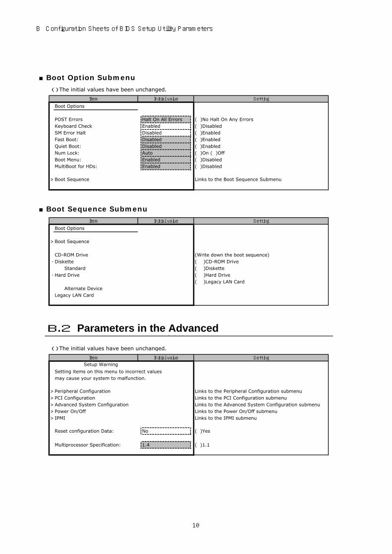
■Boot Option Submenu
( ) The initial values have been unchanged.
Setting
Boot Options
POST Errors Halt On All Errors ( )No Halt On Any ErrorsKeyboard Check Enabled ( )DisabledSM Error Halt Disabled ( )EnabledFast Boot: Disabled ( )EnabledQuiet Boot: Disabled ( )EnabledNum Lock: Auto ( )On ( )OffBoot Menu: Enabled ( )DisabledMultiBoot for HDs: Enabled ( )Disabled
> Boot Sequence Links to the Boot Sequence Submenu
■Boot Sequence Submenu
Setting
Boot Options
> Boot Sequence
CD-ROM Drive (Write down the boot sequence) - Diskette ( )CD-ROM Drive
Standard ( )Diskette - Hard Drive ( )Hard Drive
( )Legacy LAN Card Alternate DeviceLegacy LAN Card
( ) The initial values have been unchanged.
Setting
Setup Warning
Setting items on this menu to incorrect valuesmay cause your system to malfunction.
> Peripheral Configuration Links to the Peripheral Configuration submenu> PCI Configuration Links to the PCI Configuration submenu> Advanced System Configuration Links to the Advanced System Configuration submenu> Power On/Off Links to the Power On/Off submenu> IPMI Links to the IPMI submenu
Reset configuration Data: No ( )Yes
Multiprocessor Specification: 1.4 ( )1.1
Item Initial value
Item Initial value
Item Initial value
B.2 Parameters in the Advanced
10

PRIMERGY TX300 S4 Configuration Sheets
■Peripheral Configuration Submenu
( ) The initial values have been unchanged.
Setting
Peripheral Configuration
Serial 1: Auto ( )Disabled ( )Enabled ( )OS ControlledSerial Port1 Address: *1 3F8h,IRQ 4 ( )2F8h,IRQ 3 ( )3E8h,IRQ 4 ( )2E8h,IRQ 3
Serial Multiplexer: System ( )iRMC
Serial 2: Auto ( )Disabled ( )Enabled ( )OS ControlledSerial 2 Address: *2 2F8h,IRQ 3 ( )3F8h,IRQ 4 ( )3E8h,IRQ 4 ( )2E8h,IRQ 3
Parallel: Disabled ( )Auto ( )EnabledParallel Mode: *3 Bidirection ( )Printer ( )EPP ( )ECPParallel Address: *3 378h,IRQ 7 ( )278h,IRQ 5 ( )3BCh,IRQ 7
USB Host Controller: Enabled ( )DisabledUSB 2.0 Host Controller: Enabled ( )DisabledUSB BIOS Supported Devices: Auto ( )None ( )Keyboard/Mouse ( )AllUSB Boot Delay: 0s ( )3s ( )6s ( )9sUSB BIOS Hot-Plug: Enabled ( )DisabledUSB Front Enabled ( )DisabledUSB Rear Enabled ( )Disabled
> ATA Controller Config Links to the ATA Controller Config submenu
Diskette Controller: Enabled ( )DisabledMouse Controller: Auto Detect ( )Disabled ( )EnabledOnboard Video: Enabled ( )Disabled LAN Controller: LAN1 & 2 ( )Disabled ( )LAN1LAN1 Remote Boot: Disabled ( )PXE ( )iSCSI *4LAN2 Remote Boot: Disabled ( )PXE ( )iSCSI *4
*1:Appears when "Enabled" is selected for [Serial 1].
*3:Appears when "Enabled" is selected for [Parallel].*4:iSCSI is non-support.
■ATA Controller Config Submenu( ) The initial values have been unchanged.
Setting
ATA Controller Config
S-ATA Mode: Native ( )Compatible ( )AHCIPrimary IDE Channel: Enabled ( )DisabledSecondary IDE Channel: *1 Enabled ( )DisabledTertiary IDE Channel: *2 Enabled ( )DisabledQuaternary IDE Channel: *2 Enabled ( )Disabled
*1:Appears when "Compatible" is selected for [S-ATA Mode].*2:Appears when "Native,AHCI" is selected for [S-ATA Mode].
■PCI Configuration Submenu
Setting
PCI Configuration
> PCI SLOTS Configuration: Links to the PCI SLOTS Configuration Submenu> PCI IRQ Configuration: Links to the PCI IRQ Configuration Submenu
Item Initial value
*2:Appears when "Enabled" is selected for [Serial 2].
Item Initial value
Item Initial value
11

B Configuration Sheets of BIOS Setup Utility Parameters
■PCI SLOTS Configuration Submenu
( ) The initial values have been unchanged.
Setting
PCI SLOTS Configuration
PCI Slot 1 ConfigurationOption ROM SCAN: Enabled ( )Disabled
PCI Slot 2 ConfigurationOption ROM SCAN: Enabled ( )Disabled
PCI Slot 3 ConfigurationOption ROM SCAN: Disabled ( )Enabled
PCI Slot 4 ConfigurationOption ROM SCAN: Disabled ( )Enabled
PCI Slot 5 ConfigurationOption ROM SCAN: Enabled ( )Disabled PCI Slot 6 ConfigurationOption ROM SCAN: Enabled ( )Disabled PCI Slot 7 ConfigurationOption ROM SCAN: Disabled ( )Enabled
■PCI IRQ Configuration Submenu( ) The initial values have been unchanged.
Setting
PCI IRQ Configuration
PCI IRQ Line 1 : Auto ( )Disabled ( )IRQ3 ( )IRQ4 ( )IRQ5( )IRQ6 ( )IRQ7 ( )IRQ9 ( )IRQ10( )IRQ11 ( )IRQ12 ( )IRQ14 ( )IRQ15
PCI IRQ Line 2 : Auto ( )Disabled ( )IRQ3 ( )IRQ4 ( )IRQ5( )IRQ6 ( )IRQ7 ( )IRQ9 ( )IRQ10( )IRQ11 ( )IRQ12 ( )IRQ14 ( )IRQ15
PCI IRQ Line 3 : Auto ( )Disabled ( )IRQ3 ( )IRQ4 ( )IRQ5( )IRQ6 ( )IRQ7 ( )IRQ9 ( )IRQ10( )IRQ11 ( )IRQ12 ( )IRQ14 ( )IRQ15
PCI IRQ Line 4 : Auto ( )Disabled ( )IRQ3 ( )IRQ4 ( )IRQ5( )IRQ6 ( )IRQ7 ( )IRQ9 ( )IRQ10( )IRQ11 ( )IRQ12 ( )IRQ14 ( )IRQ15
PCI IRQ Line 5 : Auto ( )Disabled ( )IRQ3 ( )IRQ4 ( )IRQ5( )IRQ6 ( )IRQ7 ( )IRQ9 ( )IRQ10( )IRQ11 ( )IRQ12 ( )IRQ14 ( )IRQ15
PCI IRQ Line 6 : Auto ( )Disabled ( )IRQ3 ( )IRQ4 ( )IRQ5( )IRQ6 ( )IRQ7 ( )IRQ9 ( )IRQ10( )IRQ11 ( )IRQ12 ( )IRQ14 ( )IRQ15
PCI IRQ Line 7 : Auto ( )Disabled ( )IRQ3 ( )IRQ4 ( )IRQ5( )IRQ6 ( )IRQ7 ( )IRQ9 ( )IRQ10( )IRQ11 ( )IRQ12 ( )IRQ14 ( )IRQ15
PCI IRQ Line 8 : Auto ( )Disabled ( )IRQ3 ( )IRQ4 ( )IRQ5( )IRQ6 ( )IRQ7 ( )IRQ9 ( )IRQ10( )IRQ11 ( )IRQ12 ( )IRQ14 ( )IRQ15
Item Initial value
Item Initial value
12

PRIMERGY TX300 S4 Configuration Sheets
■Advanced System Configuration Submenu
( ) The initial values have been unchanged.
Setting
Advanced System Configuration
BIOS Work Space Location: Expansion ROM Area ( )Top of Base Memory
Memory Redundancy: Disabled ( )Mirroring ( )SparingMemory Throttling Disabled ( )EnabledMemory Power Mode Performance ( )EnergyHigh Bandwidth Enabled ( )Disabled
CPU Frequency (GHz): Automatic display the selectable frequency bymounted processor.( )_____________
CPU Thermal Management Enhanced ( )StandardEnhanced SpeedStep: *1 Disabled ( )EnabledCPU Halt Mode Enhanced ( )StandardEnhanced Idle Power State Disabled ( )EnabledCore Multi-Processing Enabled ( )DisabledCPU Mismatch Detection: Enabled ( )DisabledCPU Timeout Counter: Disabled ( )EnabledLimit CPUID functions: Disabled ( )EnabledNX Memory Protection Disabled ( )EnabledCPU MC Status Clear: Next Boot ( )Enabled ( )DisabledVirtualization Technology: *2 Disabled ( )EnabledHardware Prefetch: Enabled ( )DisabledAdjacent Sector Prefetch: Enabled ( )Disabled
High Precision Event Timer: Disabled ( )EnabledI/OAT: Disabled ( )Enabled
*1:Not appears when Xeon® Processor E5405 is installed.*2:Power off the server once and automatically power on if you finish after change the value and save it.
■Power On/Off Submenu
( ) The initial values have been unchanged.
Setting
Power On/Off
Power Off Source Software: Enabled ( )Disabled Power Button: Enabled ( )Disabled
Power On Source: BIOS Controlled ( )ACPI Controlled Remote: Disabled ( )Enabled LAN: Enabled ( )Disabled Wake Up Timer: Disabled ( )Enabled Wake Up Time: *1 [00:00:00]
Wake Up Mode: *1 Daily ( )Monthly Wake Up Day: *2 1 ( )[1~31]
Power Failure Recovery: Previous State ( )Always Off ( )Always On
*1:Appears when "Enabled" is selected for [Wake Up Timer].*2:Appears when "Monthly" is selected for [Wake Up Mode].
Item Initial value
Item Initial value
13

B Configuration Sheets of BIOS Setup Utility Parameters
■IPMI Submenu
( ) The initial values have been unchanged.
Setting
IPMI
SEL Load xx% Displays percentage of stored SELClear System Event Log: Disabled ( )EnabledEvent Log Full Mode: Overwrite ( )MaintainiRMC Time Sync: Enabled ( )Disabled
> System Event Log Displays System Event Log> SDRR Browser Displays information of sensors> LAN Settings Links to the LAN Settings submenu
■LAN Settings Submenu
( ) The initial values have been unchanged.
Setting
LAN Settings
DHCP: *1 Disabled ( )EnabledLocal IP address *1 [000.000.000.001] IP address of iRMC
[ . . . ]Subnet mask *1 [000.000.000.000] Subnet mask
[ . . . ]Gateway address *1 [000.000.000.000] Gateway address
[ . . . ]Service LAN: Enabled ( )DisabledService LAN Port: Service ( )Shared
*1:Keep the value in previous set after perform Get Default Values.
( ) The initial values have been unchanged.
Setting
Setup Password: Not installed Displays whether or not the Setup Password is set.
System Password: Not installed Displays whether or not the System Password is set.
Set Setup Password: Press Enter Enter the Setup Password.Setup Password Lock: Standard ( )ExtendedSet System Password: Press Enter Enter the System Password *1System Password Mode: System ( )Keyboard *2
System Load: Standard ( )Diskette/CDROM LockSetup Prompt: Enabled ( )DisabledVirus Warning: Disabled ( )Enabled ( )Confirm
Diskette Write: Enabled ( )DisabledFlash Write: Enabled ( )Disabled
> TPM (Security Chip) Setting Links to the TPM (Security Chip) Setting submenu
Item Initial value
Item Initial value
Item Initial value
*1:Can be set when [Setup Password] is set.
*2:Can be set when [System Password] is set.
B.3 Parameters in the Security menu
14

PRIMERGY TX300 S4 Configuration Sheets
■TPM (Security Chip) Setting Submenu
( ) The initial values have been unchanged.
Setting
TPM (Security Chip) Setting
Security Chip: Disabled ( )Enabled
Current TPM State xx and xx Displays a state of the TPM
Change TPM State: No Change ( )Enable&Activate
( )Disable&Deactivate ( )Clear
( ) The initial values have been unchanged.
Setting
O/S Boot Timeout: Disabled ( )Enabled Action: Reset ( )Continue ( )Power Cycle Timeout Value: 0 ( )[1~100]ASR&R Boot Delay: 2 ( )[1~30]Power Cycle Delay: 7 ( )[0~15]Boot Retry Counter: 3 ( )[0~7]Temperature Monitoring: Disabled ( )EnabledMemory Scrubbing: Enabled ( )Disabled
> CPU Status Links to the CPU Status submenu> Memory Status Links to the Memory Status submenu> PCI Status Links to the PCI Status submenu> Console Redirection Links to the Console Redirection submenu
■CPU Status Submenu
( ) The initial values have been unchanged.
Setting
CPU Status
CPU 1 Status Enabled ( )Failed *1 ( )Disabled *2CPU 2 Status Enabled ( )Failed *1 ( )Disabled *2
*2:Setting value when the CPU is uninstalled.
Item Initial value
*1:Appears when CPU error occurs. This can be changed to "Enabled" only.
Item Initial value
Item Initial value
B.4 Parameters in the Server menu
15

B Configuration Sheets of BIOS Setup Utility Parameters
■Memory Status Submenu( ) The initial values have been unchanged.
Setting
Memory Status
Memory Module 1A Enabled ( )Failed *1 ( )Disabled *2Memory Module 1B Enabled ( )Failed *1 ( )Disabled *2Memory Module 2A Enabled ( )Failed *1 ( )Disabled *2Memory Module 2B Enabled ( )Failed *1 ( )Disabled *2Memory Module 3A Enabled ( )Failed *1 ( )Disabled *2Memory Module 3B Enabled ( )Failed *1 ( )Disabled *2Memory Module 4A Enabled ( )Failed *1 ( )Disabled *2Memory Module 4B Enabled ( )Failed *1 ( )Disabled *2Memory Module 1C Enabled ( )Failed *1 ( )Disabled *2Memory Module 1D Enabled ( )Failed *1 ( )Disabled *2Memory Module 2C Enabled ( )Failed *1 ( )Disabled *2Memory Module 2D Enabled ( )Failed *1 ( )Disabled *2Memory Module 3C Enabled ( )Failed *1 ( )Disabled *2Memory Module 3D Enabled ( )Failed *1 ( )Disabled *2Memory Module 4C Enabled ( )Failed *1 ( )Disabled *2Memory Module 4D Enabled ( )Failed *1 ( )Disabled *2
*1: Appears when memory error occurs . This can be changed to "Enabled" only.
*2:Setting value when the memory is uninstalled.
■PCI Status Submenu( ) The initial values have been unchanged.
Setting
PCI Status
Slot 1 OK ( )Failed *1Slot 2 OK ( )Failed *1Slot 3 OK ( )Failed *1Slot 4 OK ( )Failed *1Slot 5 OK ( )Failed *1Slot 6 OK ( )Failed *1Slot 7 OK ( )Failed *1
■Console Redirection Submenu( ) The initial values have been unchanged.
Setting
Console Redirection
Console Redirection Disabled ( )EnabledPort *1 Serial1 ( )Serial2Baud Rate *1 9600 ( )1200 ( )2400 ( )4800 ( )19.2K
( )38.4K ( )57.6K ( )115.2K
Protocol *1 VT100+ ( )VT100 ( )VT100,8bit( )PC-ANSI,7bit ( )PC-ANSI
Flow Control *1 CTS/RTS ( )None ( )XON/XOFFMode *1 Enhanced ( )Standard
*1:Appears when "Enabled" is selected for [Console Redirection].
Item Initial value
Item Initial value
*1: Appears when PCI error occurs . This can be changed to "OK" only.
Item Initial value
16
PRIMERGY TX300 S4 Configuration Sheets
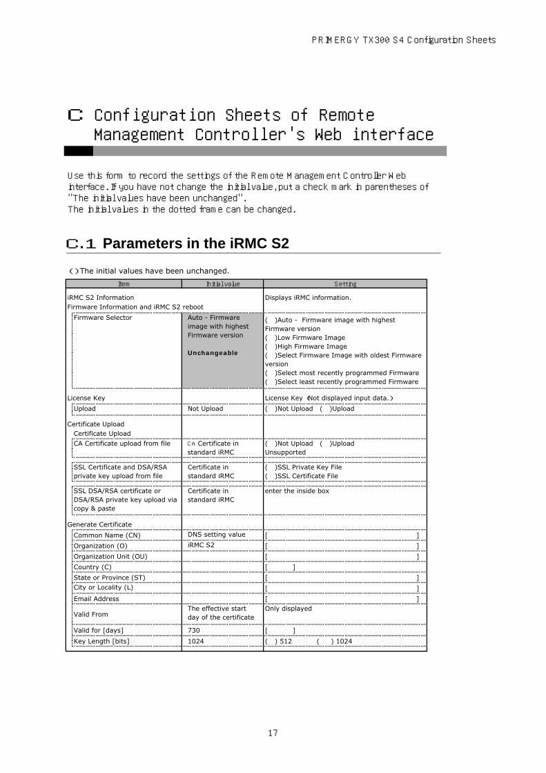
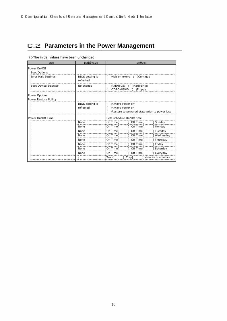
Use this form to record the settings of the Remote Management Controller Webinterface. If you have not change the initial value, put a check mark in parentheses of"The initial values have been unchanged".The initial values in the dotted frame can be changed.
( ) The initial values have been unchanged.
Setting
iRMC S2 Information Displays iRMC information.Firmware Information and iRMC S2 reboot
Firmware Selector Auto - Firmwareimage with highestFirmware version
Unchangeable
( )Auto - Firmware image with highestFirmware version( )Low Firmware Image( )High Firmware Image( )Select Firmware Image with oldest Firmwareversion( )Select most recently programmed Firmware( )Select least recently programmed Firmware
License Key License Key (Not displayed input data.)
Upload Not Upload ( )Not Upload ( )Upload
Certificate UploadCertificate Upload
CA Certificate upload from file CA Certificate instandard iRMC
( )Not Upload ( )UploadUnsupported
SSL Certificate and DSA/RSAprivate key upload from file
Certificate instandard iRMC
( )SSL Private Key File( )SSL Certificate File
SSL DSA/RSA certificate orDSA/RSA private key upload viacopy & paste
Certificate instandard iRMC
enter the inside box
Generate Certificate
Common Name (CN) DNS setting value [ ]
Organization (O) iRMC S2 [ ]
Organization Unit (OU) [ ]
Country (C) [ ]
State or Province (ST) [ ]
City or Locality (L) [ ]
Email Address [ ]
Valid FromThe effective startday of the certificate
Only displayed
Valid for [days] 730 [ ]
Key Length [bits] 1024 ( ) 512 ( ) 1024
Item Initial value
C Configuration Sheets of Remote Management Controller's Web interface
C.1 Parameters in the iRMC S2
17
C Configuration Sheets of Remote Management Controller's Web Interface
( ) The initial values have been unchanged.
Setting
Power On/Off
Boot Options
Error Halt Settings BIOS setting isreflected
( )Halt on errors ( )Continue
Boot Device Selector No change ( )PXE/iSCSI ( )Hard-drive( )CDROM/DVD ( )Froppy
Power Options
Power Restore Pollicy
BIOS setting is ( )Always Power offreflected ( )Always Power on
( )Restore to powered state prior to power loss
Power On/Off Time Sets schedule On/Off time.
None On Time[ ] Off Time[ ] Sunday
None On Time[ ] Off Time[ ] Monday
None On Time[ ] Off Time[ ] Tuesday
None On Time[ ] Off Time[ ] Wednesday
None On Time[ ] Off Time[ ] Thursday
None On Time[ ] Off Time[ ] Friday
None On Time[ ] Off Time[ ] Saturday
None On Time[ ] Off Time[ ] Everyday
0 Trap[ ] Trap[ ] Minutes in advance
Item Initial value
C.2 Parameters in the Power Management
18

PRIMERGY TX300 S4 Configuration Sheets
( ) The initial values have been unchanged.
Setting
Power consumption configuration
Power Consumption Options controll the power consumption
Power Control Mode Power Mgmt. Disabled ( )Best Performance ( )Minimum Power( )Scheduled
Power Monitoring Units Watt ( )Watt ( )BTU/h
Enable Power Monitoring Disabled ( )Enabled ( )Disabled
※
Appears when "Scheduled" is selected for [PowerControl Mode].
Sunday Time[HH:MM] no valueMode: Power Mgmt. Disabled
Time1 [ ] Mode1 ( )Power Mgmt. Disabled ( )Best Performance ( )Minimum PowerTime2 [ ] Mode2 ( )Power Mgmt. Disabled ( )Best Performance ( )Minimum Power
Monday Time[HH:MM] no valueMode: Power Mgmt. Disabled
Time1 [ ] Mode1 ( )Power Mgmt. Disabled ( )Best Performance ( )Minimum PowerTime2 [ ] Mode2 ( )Power Mgmt. Disabled ( )Best Performance ( )Minimum Power
Tuesday Time[HH:MM] no valueMode: Power Mgmt. Disabled
Time1 [ ] Mode1 ( )Power Mgmt. Disabled ( )Best Performance ( )Minimum PowerTime2 [ ] Mode2 ( )Power Mgmt. Disabled ( )Best Performance ( )Minimum Power
Wednesday Time[HH:MM] no valueMode: Power Mgmt. Disabled
Time1 [ ] Mode1 ( )Power Mgmt. Disabled ( )Best Performance ( )Minimum PowerTime2 [ ] Mode2 ( )Power Mgmt. Disabled ( )Best Performance ( )Minimum Power
Thursday Time[HH:MM] no valueMode: Power Mgmt. Disabled
Time1 [ ] Mode1 ( )Power Mgmt. Disabled ( )Best Performance ( )Minimum PowerTime2 [ ] Mode2 ( )Power Mgmt. Disabled ( )Best Performance ( )Minimum Power
Friday Time[HH:MM] no valueMode: Power Mgmt. Disabled
Time1 [ ] Mode1 ( )Power Mgmt. Disabled ( )Best Performance ( )Minimum PowerTime2 [ ] Mode2 ( )Power Mgmt. Disabled ( )Best Performance ( )Minimum Power
Saturday Time[HH:MM] no valueMode: Power Mgmt. Disabled
Time1 [ ] Mode1 ( )Power Mgmt. Disabled ( )Best Performance ( )Minimum PowerTime2 [ ] Mode2 ( )Power Mgmt. Disabled ( )Best Performance ( )Minimum Power
Power History Units Watt ( )Watt ( )BTU/h
Power History Period 1 hour ( )1 hour ( )12 hours ( )1 day( )1 week ( )2 weeks ( )1 month ( )1 year
Enable Power Monitoring check-mark ( )Enabled ( )Disabled
Power History Options
Item Initial value
Scheduled Power ConsumptionConfiguration
Power Consumption History
C.3 Parameters in the Power Consumption
19

C Configuration Sheets of Remote Management Controller's Web Interface
( ) The initial values have been unchanged.
Setting
Fan Test Sets Fan Test time.Fan Check Time 23:00 [ ] HH:MM
Analog Fans Sets the operation at the Fan malfunction.
0 FAN CPU1 continue ( )shutdown-and-power-off Deley[ ]sec
1 FAN CPU2 continue ( )shutdown-and-power-off Deley[ ]sec
2 FAN1 SYS continue ( )shutdown-and-power-off Deley[ ]sec
3 FAN2 SYS continue ( )shutdown-and-power-off Deley[ ]sec
4 FAN3 SYS continue ( )shutdown-and-power-off Deley[ ]sec
5 FAN4 SYS continue ( )shutdown-and-power-off Deley[ ]sec
6 FAN1 SYS continue ( )shutdown-and-power-off Deley[ ]sec
7 FAN2 SYS continue ( )shutdown-and-power-off Deley[ ]sec
8 FAN PSU continue ( )shutdown-and-power-off Deley[ ]sec
9 FAN PSU1 continue ( )shutdown-and-power-off Deley[ ]sec
10 FAN PSU2 continue ( )shutdown-and-power-off Deley[ ]sec
( ) The initial values have been unchanged.
Setting
Temperature Sensor Information Sets the operation at the temperaturemalfunction.
0 Ambient continue ( )shutdown-and-power-off
1 Systemboard continue ( )shutdown-and-power-off
2 CPU 1 continue ( )shutdown-and-power-off
3 CPU 2 continue ( )shutdown-and-power-off
4 DIMM-1A continue ( )shutdown-and-power-off
5 DIMM-1B continue ( )shutdown-and-power-off
6 DIMM-2A continue ( )shutdown-and-power-off
7 DIMM-2B continue ( )shutdown-and-power-off
8 DIMM-3A continue ( )shutdown-and-power-off
9 DIMM-3B continue ( )shutdown-and-power-off
10 DIMM-4A continue ( )shutdown-and-power-off
11 DIMM-4B continue ( )shutdown-and-power-off
12 DIMM-1C continue ( )shutdown-and-power-off
13 DIMM-1D continue ( )shutdown-and-power-off
14 DIMM-2C continue ( )shutdown-and-power-off
15 DIMM-2D continue ( )shutdown-and-power-off
16 DIMM-3C continue ( )shutdown-and-power-off
17 DIMM-3D continue ( )shutdown-and-power-off
18 DIMM-4C continue ( )shutdown-and-power-off
19 DIMM-4D continue ( )shutdown-and-power-off
Item Initial value
Item Initial value
Displayed FAN is changed by configuration. If it is the redundant configuration, FAN number 6 to 8 is notto be displayed. If it is not the redundant configuration, only FAN number 6 to 8 is displayed.
C.5 Parameters in the Temperature
C.4 Parameters in the Fans
20

PRIMERGY TX300 S4 Configuration Sheets
( ) The initial values have been unchanged.
Setting
System Event Log Content Displays System Event Log
Display Critical Enabled ( )Enabled ( )Disabled
Display Major Enabled ( )Enabled ( )Disabled
Display Minor Disabled ( )Enabled ( )Disabled
Display Info Disabled ( )Enabled ( )Disabled
CSS only Disabled ( )Enabled ( )Disabled
System Event Log Configuration
Display Critical Enabled ( )Enabled ( )Disabled
Display Major Enabled ( )Enabled ( )Disabled
Display Minor Disabled ( )Enabled ( )Disabled
Display Info Disabled ( )Enabled ( )Disabled
CSS only Disabled ( )Enabled ( )DisabledSEL Type Ring SEL ( )Ring SEL ( )IPMI SEL
( ) The initial values have been unchanged.
Setting
ASR&R Options
ASR & R Boot Delay(1 - 30) BIOS setting isreflected
[ ]minutes
Retry counter (0 - 7) BIOS setting isreflected
[ ]
BIOS Recovery Flash Disabled ( )Disabled ( )Enabled
Power Cycle Delay (0 - 15) BIOS setting isreflected
[ ]seconds
Watchdog Settings BIOS setting isreflected for Boot
Sets Watchdog
Software Watchdog: Disabled ( )Enabled
Continue ( )Continue ( )Reset ( )Power Cycle
timeout delay: [ ]minutes
Boot Watchdog: Disabled ( )Enabled
Continue ( )Continue ( )Reset ( )Power Cycle
timeout delay: [ ]minutes
Reply right or wrong setting to HP SIM
Software Watchdog: Disabled ( )Enabled
HP System Insight Manager(HP SIM) Integration Options
Item Initial value
Item Initial value
C.7 Parameters in the Server Management Information
C.6 Parameters in the System Event Log
21

C Configuration Sheets of Remote Management Controller's Web Interface
( ) The initial values have been unchanged.
Setting
EthernetIP configuration
MAC Address Displays MAC address of iRMC.LAN Speed Auto Negotiation ( )Auto Negotiation
( )100MBit/s Full Duplex( )100MBit/s Half Duplex( )10MBit/s Full Duplex( )10MBit/s Half Duplex
LAN Port Service LAN ( )Service LAN( )Shaerd LAN
IP Address BIOS setting is reflected [ . . . ]
Subnet Mask BIOS setting is reflected [ . . . ]
Gateway BIOS setting is reflected [ . . . ]
DHCP enable BIOS setting is reflected ( )Enabled ( )Disabled
VLAN configuration
VLAN enable Disabled ( )EnabledVLAN Id 0 [ ]1 - 4094
VLAN Priority 0 [ ]0 - 7
Ports and Network Services
Session timeout 300 [ ]60 - 60000
HTTP Port 80 [ ]1 - 65535
HTTPS Port 443 [ ]1 - 65535
Force HTTPS Disabled ( )Enabled ( )DisabledEnable Auto Refresh Enabled ( )Enabled ( )DisabledRefresh every xxx seconds 120 [ ]
Telnet Port 3172 [ ]1 - 65535
Session Drop Time 600 [ ]0,15 - 60000
SSH Port 22 [ ]1 - 65535
Telnet Enabled Disabled ( )Enabled ( )Disabled
Standard Port (via HTTP) same as HTTP Port work with HTTP Port
Secure Port (via HTTPS) sane as HTTPS Port work with HTTPS Port
Standard Port 5901 [ ]1 - 65535
DHCP Configuration
Enabled ( )Enabled ( )Disabled
Enabled ( )Enabled ( )Disabled
Enabled ( )Enabled ( )Disabled
Disabled ( )Enabled ( )Disabled
IRMC [ ]
-iRMC [ ]
DNS Settings
Enabled ( )Enabled ( )DisabledEnabled ( )Enabled ( )Disabled
domain.com [ ]
0.0.0.0 [ . . . ]
0.0.0.0 [ . . . ]
0.0.0.0 [ . . . ]
0.0.0.0 [ . . . ]
0.0.0.0 [ . . . ]
*1:When License Key is input, it is displayed.
DNS Server4
DNS Server5
DNS Domain
DNS Server1
DNS Server2
DNS Server3
iRMC S2 Name
Extension
DNS enabledObtain DNS configuration from DHCP
Register DHCP Address in DNS
Use iRMC S2 Name instead of Hostname
Add Serial Number
Add Extension
Remote Storage Ports *1
Item Initial value
Web based access
VNC based access *1
Text based accsess
C.8 Parameters in the Network Settings
22

PRIMERGY TX300 S4 Configuration Sheets
( ) The initial values have been unchanged.
Setting
SNMP Trap Destination
SNMP Community public [ ]SNMP Server1 0.0.0.0 [ ]SNMP Server2 0.0.0.0 [ ]SNMP Server3 0.0.0.0 [ ]SNMP Server4 0.0.0.0 [ ]SNMP Server5 0.0.0.0 [ ]SNMP Server6 0.0.0.0 [ ]SNMP Server7 0.0.0.0 [ ]
( ) The initial values have been unchanged.
Setting
Global Email Paging Configuration
Email Alerting Enable Disabled ( )Enabled
SMTP Retries (0-7) 3 [ ]
SMTP Retry Delay (0-255) 240 [ ]
SMTP Response Timeout 45 [ ]
Primary SMTP Server Configuration
SMTP Server 0.0.0.0 [ ]
SMTP Port 25 [ ]1 - 65535
Auth Type None ( )None ( )SMTP AUSH(RFC2554)
Auth UserName *1 [ ]
Auth Password *1 *Displays
Confirm Password *1 *Displays
Secondary SMTP Server Configuration
SMTP Server 0.0.0.0 [ ]
SMTP Port 25 [ ]1 - 65535
Auth Type None ( )None ( )SMTP AUSH(RFC2554)
Auth UserName *1 [ ]
Auth Password *1 *Displays
Confirm Password *1 *Displays
Mail Format dependend Configuration
From [email protected] [ ]
Subject FixedMailSubject [ ]
Message FixedMailMessage [ ]
Admin. Name ITS_UserInfo0 [ ]
Admin. Phone ITS_UserInfo1 [ ]
REMCS Id Unchangeable
Server URL http://www.server.com [ ]
*1:Appears when "SMTP AUTH(RFC 2554)" is selected for [Auth Type].
Item Initial value
Item Initial value
C.10 Parameters in the Email Alerting
C.9 Parameters in the SNMP Trap Alerting
23

C Configuration Sheets of Remote Management Controller's Web Interface
( ) The initial values have been unchanged.
Setting
iRMC S2 User Information
ID/Name 2 admin 2 [ ]
None 3 [ ]
None 4 [ ]
None 5 [ ]
None 6 [ ]
None 7 [ ]
None 8 [ ]
None 9 [ ]
None 10 [ ]
None 11 [ ]
None 12 [ ]
None 13 [ ]
None 14 [ ]
None 15 [ ]
None 16 [ ]
The User Name is displayed that is created by [New User]. Clicking "UserName" displays a settingwindow for each UserName.The default settings or the settings that are configured when creating a new user are displayed on thesetting window. The setting is available up to user number 15th. (Unable to set at user number 1.)
Item Initial value
C.11 Parameters in the User Management
24

PRIMERGY TX300 S4 Configuration Sheets
■User "admin(2)" Configuration
( ) The initial values have been unchanged.
Setting
iRMC S2 User Information
User Enabled Enabled ( )Disabled ( )Enabled
Name admin [ ]
Password *Displays
Confirm Password *Enter the password again to confirm it.
User Description User02 Description [ ]
User Shell (Text Access) Remote Manager ( )SMASH CLP( )CLI Shell( )Remote Manager( )IPMI Basic Mode( )IPMI Terminal Mode( )None
Privilege / Shell
LAN Channel OEM ( )User ( )Operater ( )Administorator ( )OEM
Serial Channel OEM ( )User ( )Operater ( )Administorator ( )OEM
Configure User Accounts Enabled ( )Disabled ( )Enabled
Configure iRMC S2 settings Enabled ( )Disabled ( )Enabled
Video Redirection Enabled Enabled ( )Disabled ( )Enabled
Remote Storage Enabled Enabled ( )Disabled ( )Enabled
Email Configuration
Email Enabled Disabled ( )Disabled ( )Enabled
Mail Format Standard ( )Standard ( )Fixed Subject
( )ITS Format ( )Fujitsu REMCS-Format
Prefered Mail Server Automatic ( )Automatic ( )Primary ( )Secondary
Email Address [email protected] [ ]
Fan Sensors WARNING ( )NONE ( )CRITICAL ( )WARNING ( )ALL
Temperature Sensors WARNING ( )NONE ( )CRITICAL ( )WARNING ( )ALL
Critical Hardware Errors ALL ( )NONE ( )CRITICAL ( )WARNING ( )ALL
System Hang CRITICAL ( )NONE ( )CRITICAL ( )WARNING ( )ALL
POST Errors ALL ( )NONE ( )CRITICAL ( )WARNING ( )ALL
Security WARNING ( )NONE ( )CRITICAL ( )WARNING ( )ALL
System Status NONE ( )NONE ( )CRITICAL ( )WARNING ( )ALL
Disk Drivers & Controllers CRITICAL ( )NONE ( )CRITICAL ( )WARNING ( )ALL
Network Interface WARNING ( )NONE ( )CRITICAL ( )WARNING ( )ALL
Remote Management CRITICAL ( )NONE ( )CRITICAL ( )WARNING ( )ALL
System Power WARNING ( )NONE ( )CRITICAL ( )WARNING ( )ALL
Memory CRITICAL ( )NONE ( )CRITICAL ( )WARNING ( )ALL
Others NONE ( )NONE ( )CRITICAL ( )WARNING ( )ALL
Item Initial value
This is the UserName setting window for user ID 2.The user ID 2 (admin) is the UserName/ID as initial value.
25
C Configuration Sheets of Remote Management Controller's Web Interface
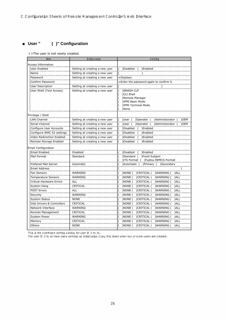
■ User " ( )" Configuration
( ) The user is not newly created.
Setting
Access Information
User Enabled Setting at creating a new user ( )Disabled ( )Enabled
Name Setting at creating a new user [ ]
Password Setting at creating a new user *Displays
Confirm Password *Enter the password again to confirm it.
User Description Setting at creating a new user [ ]
User Shell (Text Access) Setting at creating a new user ( )SMASH CLP( )CLI Shell( )Remote Manager( )IPMI Basic Mode( )IPMI Terminal Mode( )None
Privilege / Shell
LAN Channel Setting at creating a new user ( )User ( )Operater ( )Administorator ( )OEM
Serial Channel Setting at creating a new user ( )User ( )Operater ( )Administorator ( )OEM
Configure User Accounts Setting at creating a new user ( )Disabled ( )Enabled
Configure iRMC S2 settings Setting at creating a new user ( )Disabled ( )Enabled
Video Redirection Enabled Setting at creating a new user ( )Disabled ( )Enabled
Remote Storage Enabled Setting at creating a new user ( )Disabled ( )Enabled
Email Configuration
Email Enabled Disabled ( )Disabled ( )Enabled
Mail Format Standard ( )Standard ( )Fixed Subject( )ITS Format ( )Fujitsu REMCS-Format
Prefered Mail Server Automatic ( )Automatic ( )Primary ( )Secondary
Email Address [ ]
Fan Sensors WARNING ( )NONE ( )CRITICAL ( )WARNING ( )ALL
Temperature Sensors WARNING ( )NONE ( )CRITICAL ( )WARNING ( )ALL
Critical Hardware Errors ALL ( )NONE ( )CRITICAL ( )WARNING ( )ALL
System Hang CRITICAL ( )NONE ( )CRITICAL ( )WARNING ( )ALL
POST Errors ALL ( )NONE ( )CRITICAL ( )WARNING ( )ALL
Security WARNING ( )NONE ( )CRITICAL ( )WARNING ( )ALL
System Status NONE ( )NONE ( )CRITICAL ( )WARNING ( )ALL
Disk Drivers & Controllers CRITICAL ( )NONE ( )CRITICAL ( )WARNING ( )ALL
Network Interface WARNING ( )NONE ( )CRITICAL ( )WARNING ( )ALL
Remote Management CRITICAL ( )NONE ( )CRITICAL ( )WARNING ( )ALL
System Power WARNING ( )NONE ( )CRITICAL ( )WARNING ( )ALL
Memory CRITICAL ( )NONE ( )CRITICAL ( )WARNING ( )ALL
Others NONE ( )NONE ( )CRITICAL ( )WARNING ( )ALL
Item Initial value
This is the UserName setting window for user ID 3 to 16.The user ID 3 to 16 have same settings as initial value. Copy this sheet when two or more users are created.
26
PRIMERGY TX300 S4 Configuration Sheets
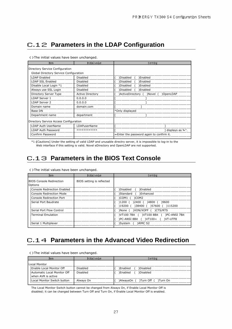
( ) The initial values have been unchanged.
Setting
Directory Service Configuration
Global Directory Service Configuration
LDAP Enabled Disabled ( )Disabled ( )EnabledLDAP SSL Enabled Disabled ( )Disabled ( )EnabledDisable Local Login *1 Disabled ( )Disabled ( )Enabled
Always use SSL Login Disabled ( )Disabled ( )Enabled
Directory Server Type Active Directory ( )ActiveDirectory ( )Novel ( )OpenLDAP
LDAP Server 1 0.0.0.0 [ ]
LDAP Server 2 0.0.0.0 [ ]
Domain name domain.com [ ]
Base DN *Only displayed
Department name department [ ]
Directory Service Access Configuration
LDAP Auth UserName LDAPuserName [ ]
LDAP Auth Password ************ [ ] displays as "*".
Confirm Password *Enter the password again to confirm it.
( ) The initial values have been unchanged.
Setting
BIOS setting is reflected
Console Redirection Enabled ( )Disabled ( )Enabled
Console Redirection Mode ( )Standard ( )Enhanced
Console Redirection Port ( )COM1 ( )COM2
Serial Port Baudrate ( )1200 ( )2400 ( )4800 ( )9600( )19200 ( )38400 ( )57600 ( )115200
Serial Port Flow Control ( )None ( )XON/XOFF ( )CTS/RTS
Terminal Emulation ( )VT100 7Bit ( )VT100 8Bit ( )PC-ANSI 7Bit
( )PC-ANSI 8Bit ( )VT100+ ( )VT-UTF8
Serial 1 Multiplexer ( )System ( )iRMC S2
( ) The initial values have been unchanged.
Setting
Enable Local Monitor Off Disabled ( )Enabled ( )Disabled
Automatic Local Monitor Offwhen AVR is active
Disabled ( )Enabled ( )Disabled
Local Monitor Switch button Always On ( )AlwaysOn ( )Turn Off ( )Turn On
Item Initial value
*1:[Cautions] Under the setting of valid LDAP and unusable directry server, it is impossible to log-in to the Web interface if this setting is valid. Novel eDirectory and OpenLDAP are not supported.
Local Monitor
The Local Monitor Switch button cannot be changed from Always On, if Enable Local Monitor Off isdisabled; it can be changed between Turn Off and Turn On, if Enable Local Monitor Off is enabled.
BIOS Console RedirectionOptions
Item Initial value
Item Initial value
C.13 Parameters in the BIOS Text Console
C.14 Parameters in the Advanced Video Redirection
C.12 Parameters in the LDAP Configuration
27

C Configuration Sheets of Remote Management Controller's Web Interface
Use this form to record the definitions of the disk groups and the logical drivesin the RAID configuration (array configuration).
■Content of Definition of the Disk Group
HDD modelname
HDDcapacity
Disk group / Spare disk *
(e.g.) Bay1 PG-HDB75A 73.4GB( )Disk group [0]( )Spare disk
(e.g.) Bay2 PG-HDB75A 73.4GB( )Disk group [0]( )Spare disk
Bay1( )Disk group [ ]( )Spare disk
Bay2( )Disk group [ ]( )Spare disk
Bay3( )Disk group [ ]( )Spare disk
Bay4( )Disk group [ ]( )Spare disk
Bay5( )Disk group [ ]( )Spare disk
Bay6( )Disk group [ ]( )Spare disk
InstallationHDD Slot / Bay
Installation PCI Slot:( )
*: Depends on the hard disk to be used, select either of 2.5 inch or 3.5 inch.
●When using the 3.5 inch hard disk
D Design Sheet of the RAID Configuration
D.1 For RAID 5/6 SAS based on LSI MegaRAID
28

PRIMERGY TX300 S4 Configuration Sheets
HDD modelname
HDDcapacity
Disk group / Spare disk *
(e.g.) Bay 1 PG-HDB75A 73.4GB( )Disk group [0]( )Spare disk
(e.g.) Bay 2 PG-HDB75A 73.4GB( )Disk group [0]( )Spare disk
Bay 1( )Disk group [ ]( )Spare disk
Bay 2( )Disk group [ ]( )Spare disk
Bay 3( )Disk group [ ]( )Spare disk
Bay 4( )Disk group [ ]( )Spare disk
Bay 5( )Disk group [ ]( )Spare disk
Bay 6( )Disk group [ ]( )Spare disk
Bay 7( )Disk group [ ]( )Spare disk
Bay 8( )Disk group [ ]( )Spare disk
Bay 9( )Disk group [ ]( )Spare disk
Bay 10( )Disk group [ ]( )Spare disk
Bay 11( )Disk group [ ]( )Spare disk
Bay 12( )Disk group [ ]( )Spare disk
Bay 13( )Disk group [ ]( )Spare disk
Bay 14( )Disk group [ ]( )Spare disk
Bay 15( )Disk group [ ]( )Spare disk
Bay 16( )Disk group [ ]( )Spare disk
Bay 17( )Disk group [ ]( )Spare disk
Bay 18( )Disk group [ ]( )Spare disk
Bay 19( )Disk group [ ]( )Spare disk
Bay 20( )Disk group [ ]( )Spare disk
●When using the 2.5 inch hard disk
*:When the hard disk is included in the disk group, put a checkmark to "Disk group" and fill in the disk group number in [ ]. The disk group number is allocated in order defining it like 0, 1, 2, …. When the hard disk is set as a spare disk, put a checkmark to "Spare disk".
InstallationHDD Slot / Bay
29
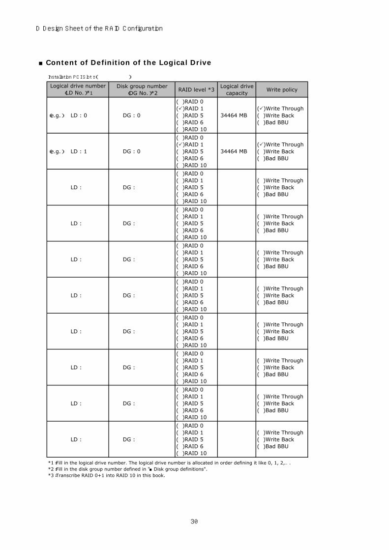
D Design Sheet of the RAID Configuration
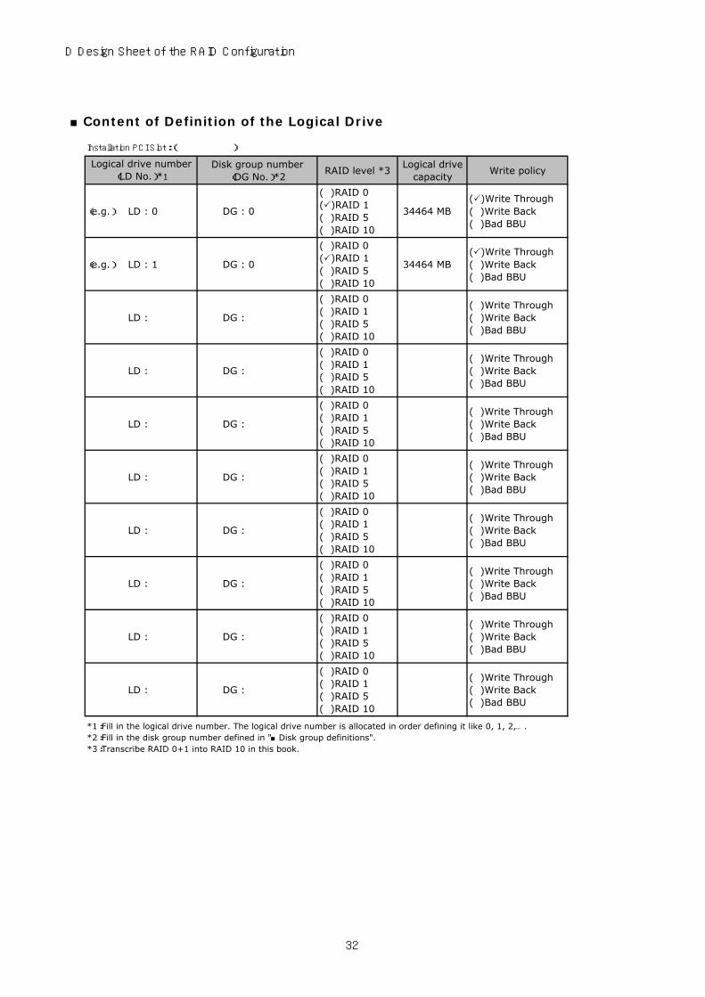
■Content of Definition of the Logical Drive
Disk group number(DG No.)*2
RAID level *3Logical drive
capacityWrite policy
(e.g.) LD : 0 DG : 0
( )RAID 0( )RAID 1( )RAID 5( )RAID 6( )RAID 10
34464 MB( )Write Through( )Write Back( )Bad BBU
(e.g.) LD : 1 DG : 0
( )RAID 0( )RAID 1( )RAID 5( )RAID 6( )RAID 10
34464 MB( )Write Through( )Write Back( )Bad BBU
LD : DG :
( )RAID 0( )RAID 1( )RAID 5( )RAID 6( )RAID 10
( )Write Through( )Write Back( )Bad BBU
LD : DG :
( )RAID 0( )RAID 1( )RAID 5( )RAID 6( )RAID 10
( )Write Through( )Write Back( )Bad BBU
LD : DG :
( )RAID 0( )RAID 1( )RAID 5( )RAID 6( )RAID 10
( )Write Through( )Write Back( )Bad BBU
LD : DG :
( )RAID 0( )RAID 1( )RAID 5( )RAID 6( )RAID 10
( )Write Through( )Write Back( )Bad BBU
LD : DG :
( )RAID 0( )RAID 1( )RAID 5( )RAID 6( )RAID 10
( )Write Through( )Write Back( )Bad BBU
LD : DG :
( )RAID 0( )RAID 1( )RAID 5( )RAID 6( )RAID 10
( )Write Through( )Write Back( )Bad BBU
LD : DG :
( )RAID 0( )RAID 1( )RAID 5( )RAID 6( )RAID 10
( )Write Through( )Write Back( )Bad BBU
LD : DG :
( )RAID 0( )RAID 1( )RAID 5( )RAID 6( )RAID 10
( )Write Through( )Write Back( )Bad BBU
Logical drive number(LD No.)*1
*1:Fill in the logical drive number. The logical drive number is allocated in order defining it like 0, 1, 2, ….*2:Fill in the disk group number defined in "■Disk group definitions".*3:Transcribe RAID 0+1 into RAID 10 in this book.
Installation PCI Slot:( )
30

PRIMERGYTX300 S4 Configuration Sheets
■Content of Definition of the Logical Drive
HDD modelname
HDDcapacity
Logical drive capacity
(e.g.) Bay 0 PG-HDB75A 73.4GB 69618 MB
(e.g.) Bay 1 PG-HDB75A 73.4GB 69618 MB
Bay 0
Bay 1
■Content of Definition of the Disk Group
HDD modelname
HDDcapacity
Disk group / Spare disk *
(e.g.) Bay 1 PG-HDB75A 73.4GB( )Disk group [0]( )Spare disk
(e.g.) Bay 2 PG-HDB75A 73.4GB( )Disk group [0]( )Spare disk
Bay 1( )Disk group [ ]( )Spare disk
Bay 2( )Disk group [ ]( )Spare disk
Bay 3( )Disk group [ ]( )Spare disk
Bay 4( )Disk group [ ]( )Spare disk
Bay 5( )Disk group [ ]( )Spare disk
Bay 6( )Disk group [ ]( )Spare disk
Bay 7( )Disk group [ ]( )Spare disk
Bay 8( )Disk group [ ]( )Spare disk
Bay 9( )Disk group [ ]( )Spare disk
Bay 10( )Disk group [ ]( )Spare disk
Bay 11( )Disk group [ ]( )Spare disk
Bay 12( )Disk group [ ]( )Spare disk
Installation PCI Slot:( )
InstallationHDD Slot / Bay
*:When the hard disk is included in the disk group, put a checkmark to "Disk group" and fill in the disk group number in [ ]. The disk group number is allocated in order defining it like 0, 1, 2, …. When the hard disk is set as a spare disk, put a checkmark to "Spare disk".
Installed position
D.2 For Integrated Mirroring SAS
D.3 For MegaRAID SAS 8344ELP
31
D Design Sheet of the RAID Configuration
■Content of Definition of the Logical Drive
Disk group number(DG No.)*2
RAID level *3Logical drive
capacityWrite policy
(e.g.) LD : 0 DG : 0
( )RAID 0( )RAID 1( )RAID 5( )RAID 10
34464 MB( )Write Through( )Write Back( )Bad BBU
(e.g.) LD : 1 DG : 0
( )RAID 0( )RAID 1( )RAID 5( )RAID 10
34464 MB( )Write Through( )Write Back( )Bad BBU
LD : DG :
( )RAID 0( )RAID 1( )RAID 5( )RAID 10
( )Write Through( )Write Back( )Bad BBU
LD : DG :
( )RAID 0( )RAID 1( )RAID 5( )RAID 10
( )Write Through( )Write Back( )Bad BBU
LD : DG :
( )RAID 0( )RAID 1( )RAID 5( )RAID 10
( )Write Through( )Write Back( )Bad BBU
LD : DG :
( )RAID 0( )RAID 1( )RAID 5( )RAID 10
( )Write Through( )Write Back( )Bad BBU
LD : DG :
( )RAID 0( )RAID 1( )RAID 5( )RAID 10
( )Write Through( )Write Back( )Bad BBU
LD : DG :
( )RAID 0( )RAID 1( )RAID 5( )RAID 10
( )Write Through( )Write Back( )Bad BBU
LD : DG :
( )RAID 0( )RAID 1( )RAID 5( )RAID 10
( )Write Through( )Write Back( )Bad BBU
LD : DG :
( )RAID 0( )RAID 1( )RAID 5( )RAID 10
( )Write Through( )Write Back( )Bad BBU
Logical drive number(LD No.)*1
*1:Fill in the logical drive number. The logical drive number is allocated in order defining it like 0, 1, 2, ….*2:Fill in the disk group number defined in "■Disk group definitions".*3:Transcribe RAID 0+1 into RAID 10 in this book.
Installation PCI Slot:( )
32

PRIMERGY TX300 S4 Configuration Sheets
When setting up the server using ServerStart, select the setting values and put a check mark in parentheses below in advance to ensure setup is performed smoothly.
Setting
( ) Logical Drive View (The system will be used as it is, with the current RAID configuration)
( ) Mass Storage Controller View (The RAID configuration can be specified)
( ) RAID ( ) SCSI( ) Fibrechannel ( ) IDE
( ) Automatically ( ) Manually
( ) Delete Existing RAID Array
RAID Level
Number of Disks
HotSpare ( ) Yes ( ) No
( ) NTFS ( ) FAT
( ) Auto setting ( ) MB
( ) Execute ( ) Do not execute
( ) Boot ( ) OS ( ) Data
Disk ↓Make copies when installing multiple disks.
Partition ↓Make copies when more sheets are needed.
Volume label
File system
Partition size
Quick format
Partition Usage
Controller Number
Configure RAID:
Manually
Parameters
Controller
When you select "RAID" with controller's typeConfigure RAID
Existing RAID ArrayController Vendor
E Design Sheet
E.1 RAID / Disk Wizard
33
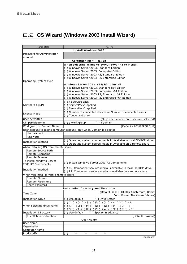
E Design Sheet
Setting
When selecting Windows Server 2003/R2 to install( ) Windows Server 2003, Standard Edition( ) Windows Server 2003, Enterprise Edition( ) Windows Server 2003 R2, Standard Edition( ) Windows Server 2003 R2, Enterprise Edition
Windows Server 2003 x64/R2 to install( ) Windows Server 2003, Standard x64 Edition( ) Windows Server 2003, Enterprise x64 Edition( ) Windows Server 2003 R2, Standard x64 Edition( ) Windows Server 2003 R2, Enterprise x64 Edition
( ) no service pack( ) ServicePack1 applied( ) ServicePack2 applied( ) Number of connected devices or Number of connected users( ) Concurrent users
(Only when concurrent users are selected)( ) a work group ( ) a domain
(Default - MYUSERGROUP)
( ) Operating system source media in Available in local CD-ROM drive( ) Operating system source media in Available on a remote share
( ) Install Windows Server 2003 R2 Components
( ) R2 Components source media is available in local CD-ROM drive( ) R2 Components source media is available on a remote share
(Default -(GMT+01:00) Amsterdam, Berlin,Bern, Rome, Stockholm, Vienna)
( ) Use default ( ) Drive Letter( ) C: ( ) D: ( ) E: ( ) F: ( ) G: ( ) H: ( ) I: ( ) J:( ) K: ( ) L: ( ) M: ( ) N: ( ) O: ( ) P: ( ) Q: ( ) R:( ) S: ( ) T: ( ) U: ( ) V: ( ) W: ( ) X: ( ) Y: ( ) Z:( ) Use default ( ) Specify in advance
(Default - \winnt)
( ) ― ― ― ―
User NameUser NameOrganization
Product-IDComputer Name
Remote UsernameReote Password
(continued)
When selecting drive name
Installation DirectoryInstallation destination
Installation Directory and Time zone
Time Zone
Installation Drive
Installation method
To install Windows Server2003 R2 Components
When you install it from a remote shareRemote Source
Remote Password
Installation method
when installing OS from remote shareRemote Source Path
Password
User account to create computer account (only when Domain is selected)User account
Remote Username
Operating System Type
Parameters
Install Windows 2003Password for Administratoraccount
Computer Identification
Workgroup or Domain Name
ServicePack(SP)
User permittedwill participate in
License Mode
E.2 OS Wizard (Windows 2003 Install Wizard)
34

PRIMERGY TX300 S4 Configuration Sheets
Setting
( ) 640 * 480 ( ) 800 * 600 ( ) 1024 * 768( ) 1156 * 864 ( ) 1280 * 1024 ( ) 1600 * 1200( ) 60 ( ) 70 ( ) 72 ( ) 75 ( ) 80 ( ) 85 ( ) 100( ) 16 colors ( ) 256 colors ( ) High Color(16bits)( ) True Color(24bits) ( ) True Color(32bits)
( ) Install Unattended( ) Install Manually
( ) TCP/IP ( ) NWIPX ( ) NetBEUI ( ) Apple Talk( ) DLC ( ) NetMon ( ) PPTP
( ) Use DHCPIP-AddressSubnet MaskDefault GatewayIP address (additional) (only when added)
Subnet mask (additional) (only when added)
Default gateway (additional) (only when added)
DNS domain name (only when specified)
DNS server address (only when specified)Use WINS ( ) UseWINS server address DHCP (only when selected to use)
( ) Use NetBIOS setting from the DHCP Server( ) Use NetBIOS over TCP/IP( ) Do not use NetBIOS over TCP/IP
Internal network number 0xNetwork number 0xFrame type
( ) TCP/IP ( ) NWIPX ( ) NetBEUI ( ) Apple Talk( ) DLC ( ) NetMon ( ) PPTP( ) Use DHCP
IP AddressSubnet MaskDefault GatewayIP address (additional) (only when added)Subnet mask (additional) (only when added)Default gateway (additional) (only when added)DNS domain name (only when specified)DNS server address (only when specified)Use WINS ( ) UseWINS server address DHCP (only when selected to use)
( ) Use NetBIOS setting from the DHCP Server( ) Use NetBIOS over TCP/IP( ) Do not use NetBIOS over TCP/IP
Internal network number 0xNetwork number 0xFrame type
(continued)
Vrefresh
NetBIOS Option
Adap
ter 1
Connection name
BitsPerPel
Network protocol
Installation method
Network protocol property (for auto-installation)
Do n
ot u
se DH
CP
Parameters
Available Protocols
Use of DHCP (When TCP/IP selected)
Display settings
Resolution
Copy this sheet to install multiple adapters.
Only when NWIPX is selected
Adap
ter 2
Connection nameProtocol binding to thisadapterUse of DHCP (When TCP/IP selected)
Do n
ot u
se DH
CP
NetBIOS Option
Only when NWIPX is selected
35

E Design Sheet
Setting
( ) Install default Components( ) Install customized Components
( ) R2 Components
( ) Application Mode(ADAM)
( ) Claims-Aware Applications( ) Traditional Applications( ) Federation Service( ) Federation Service Proxy
( ) DFS Management( ) DFS Replication Service
( ) Management Console
( ) User Name Mapping( ) Microsoft Services for NFS Administration( ) Client for NFS( ) Server for NFS( ) RPC Portmapper( ) RPC External Data Representation( ) Server For NFS Authentication
( ) Administration Components( ) Password Synchronisation( ) Server For NIS
Enable Windows Sharepoint Services
( ) Common Log File System( ) Microsoft .NET Framework2.0(English)( ) Microsoft .NET Framework2.0(International)( ) Microsoft .NET Framework2.0 Languagepack( ) Print Management Console( ) Storage Manager SAN( ) Storage Ressource Manager( ) Windows Subsystem for UNIX based Applications
( ) uninstall hidden CFSCommonUIFX( ) uninstall hidden DFSExt( ) uninstall hidden DFSRHelper( ) uninstall set of files from FileServerManagement Console
Uninstall Componennts
(continued)
Microsoft Services for NFS
Unix Identity Management
Windows SharePoint Services
Additional Components
Only when selecting R2 components to install
Active Directory
Distributed File System
File Server
Software Components
Select installation method
R2
Parameters
36

PRIMERGY TX300 S4 Configuration Sheets
Setting
Constitution of Internet Explorer security enhancement
Accessories
( ) clipboard viewer( ) Desktop Wallpaper( ) Document Template( ) Paint( ) All available mousepointers( ) Word pad( ) Calculator( ) Character Map
Accessibility Wizard ( ) InstallCommunications ( ) Chat ( ) Hyper Terminal
ASP.NET web developmentplatform
( ) Install
Application server console ( ) Install
Internet informationservices(IIS)
( ) FrontPage 2002 Server Extensions( ) FTP (File Transfer Protocol) service( ) NNTP Service - NNTP Service( ) SMTP Service - SMTP Service( ) World Wide Web Server - Internet Information Services ASP support( ) World Wide Web Server - Internet Information Services web DAV publishing
( ) World Wide Web Server - World Wide Web (WWW) Service( ) World Wide Web Server - Internet Information Services internet data connector( ) World Wide Web Server - Internet Information Services web user interface
network COM + access ( ) InstallDTC network access ( ) Install
( ) Install( ) Install( ) Install( ) Install
( ) Install ( ) Server components of the Certificate Services( ) Web client component of the Certificate Services( ) Install ( ) POP3 main service ( ) POP3 web user interface
(Default - \Inetpub\Ftproot)
(Default - \Inetsrv\WWWroot)
( ) give a authorization to remote access to this computer.
( ) risk-free security( ) mild security( ) number of connected devices ( ) number of connected users
FTP service property (Only when FTP service is selected)FTP site directory
WWW service property (Only when WWW service is selected)
License mode
WWW server directoryTerminal server property (Only when terminal server is selected)
Remote DesktopPlease select the default accesspermission for compatible application.
POP3 root component
(continued)
Terminal ServicesTerminal Services licensingRemote install Services
Certificate Service
Application server
Indexing Server Files
(Continuation of Software Components)
Only when selecting component to install
Parameters
Application and utilities
Constitution of Internet Explorersecurity enhancement
( ) Administrator group use( ) All other user group use
37

E Design Sheet
Setting
( ) Services for Macintosh (SFM)( ) Print Service for Macintosh( ) Print Service for UNIX
( ) WINS Server( ) Internet Authentication Service (IAS)( ) MS DNS Server( ) Simple TCP/IP Service( ) MS DHCP Serve
( ) Network Monitor tools( ) SNMP Service (Required to install SNMP-ServerView)
( ) Send
( ) Receive(only when specified)
( ) Physical ( ) Datalink and sub network( ) End-to-End ( ) Application ( ) Internet
( ) Install
( ) Create a domain in a new forest( ) Additional domain controller of the existing domain( ) Create a new child domain under the existing domain tree( ) Create a new domain tree in the existing fores
( ) Permit
Domain NetBIOS nameCreate a new domain tree in the existing forest (only when selected)
Domain NetBIOS name
User namePasswordDomain nameComplete DNS name of the new domain
PasswordDomainComplete DNS name of the parent domainNew child domain name
DomainComplete DNS name of the existing domain
Create a new child domain under the existing domain tree (only when selected)User name
Trap
Send authentication trap
Agent
Address
User namePassword
Contact
Service
(continued)
Receivable community nameReceive SNMP packet from all hostsHost name
Active Directory details setting (only when DNS is selected)Install Active Directory
Active Directory type
Database folder
Services
Other network File and Print Services
Trap destinationSecurity
SNMP details (Only when SNMP is selected)
Community name
Parameters
Complete DNS name of the new domainDomain NetBIOS name
Additional domain controller of the existing domain (only when selected)
Log folderSYSVOL folder locationCompatibility with Windows 2000 or earlier
Create a domain in a new forest (only when selected)
Networking Services
Management and Monitoring Tools
38
PRIMERGY TX300 S4 Configuration Sheets
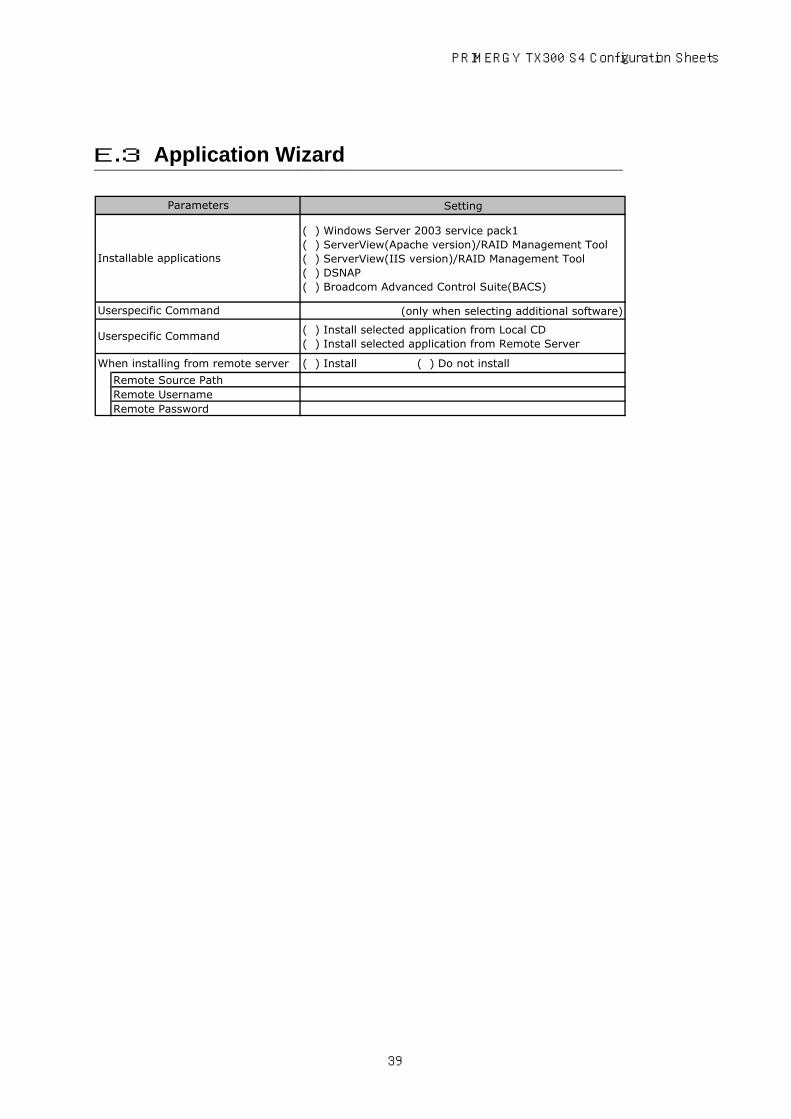
Setting
( ) Windows Server 2003 service pack1( ) ServerView(Apache version)/RAID Management Tool( ) ServerView(IIS version)/RAID Management Tool( ) DSNAP( ) Broadcom Advanced Control Suite(BACS)
(only when selecting additional software)
( ) Install selected application from Local CD( ) Install selected application from Remote Server
When installing from remote server ( ) Install ( ) Do not install
Remote Source PathRemote UsernameRemote Password
Parameters
Installable applications
Userspecific Command
Userspecific Command
E.3 Application Wizard
39

F Accident Sheet
□ PRIMERGY TX300 S4 (PG )
OS
DATE/TIME
Phase of accident
Yes / NoAttached paper
Name (Product ID)
Environment
LAN/WAN config.
F Accident Sheet
What did you do?, what message? etc.
40

• The contents of this manual may be revised without prior notice. • Fujitsu assumes no liability for damages to third party copyrights or other rights arising from the use of any information in this manual. • No part of this manual may be reproduced in any form without the prior written permission of Fujitsu.
PRIMERGY TX300 S4
Configuration SheetsCA92276-8329-01
Issued on December, 2008Issued by FUJITSU LIMITED