Embed Size (px)
Citation preview
1
Lightning and surge protection in Telecom Networks
Abstract: This study paper describes the mechanism by which lightning is generated and the ways by which high voltages produced by lightning discharges find their way into instrumentation and communications systems. Detailed analysis on lightning and surges occurring in Telecom Network and methods for providing protection from lightning and surges to minimize losses/damages have been dealt in the paper. When it comes to losses of electrical and electronic equipment, few events can match the destruction caused by lightning and surges (transients). Since microprocessor-based equipment functions with faster operating speeds and lower operating voltage than other equipment, surges and electrical noise classified as nonthreatening are significantly more damaging.
A Telecom Service provider can greatly reduce its risk of equipment damage, component degradation and system disruptions with a robust surge protection system. An electrical transient is a short duration, high energy impulse that is imparted on the normal electrical power system whenever there is a sudden change in the electrical circuit. The surges can originate from a variety of sources, both internal and external to a network. The most obvious source is from lightning, but surges can also come from normal utility switching operations, unintentional grounding of electrical conductors (such as when an overhead power line falls to the ground). 2.0 Introduction: Benjamin Franklin suggested the use of a conventional metallic rod to attract the lightning strikes and provide safety via a conduction path to ground after his famous kite experiment. From the time of Franklin, many studies and measurement of lightning strikes have been conducted; and many improvements in lightning theory and protection systems have been achieved. 3.0 Lightning strike: The lightning strike is the phenomenon occurring during the air ground or ground air discharge of static electricity. 3.1 Lightning Formation
The sky is filled with electric charge. In a calm sky, the positive (+) and negative (-) charges are evenly spaced throughout the atmosphere. Therefore, a calm sky has a neutral charge.
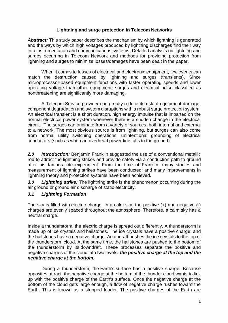
Inside a thunderstorm, the electric charge is spread out differently. A thunderstorm is made up of ice crystals and hailstones. The ice crystals have a positive charge, and the hailstones have a negative charge. An updraft pushes the ice crystals to the top of the thunderstorm cloud. At the same time, the hailstones are pushed to the bottom of the thunderstorm by its downdraft. These processes separate the positive and negative charges of the cloud into two levels: the positive charge at the top and the negative charge at the bottom.
During a thunderstorm, the Earth's surface has a positive charge. Because opposites attract, the negative charge at the bottom of the thunder cloud wants to link up with the positive charge of the Earth's surface. Once the negative charge at the bottom of the cloud gets large enough, a flow of negative charge rushes toward the Earth. This is known as a stepped leader. The positive charges of the Earth are
2
attracted to this stepped leader, so a flow of positive charge moves into the air. When the stepped leader and the positive charge from the earth meet, a strong electric current carries positive charge up into the cloud. This electric current is known as the return stroke and humans can see it as lightning.
Fig1. Lightning formation
The current which moves upward causing heating effect on the atmosphere produces the violent air expansion which is known as thunder clap. The initial leader stroke and main return stroke are generally followed by subsequent leaders and return strokes in rapid succession. Up to 42 strokes have been recorded as forming one discharge. Strokes spacing is in tens of milliseconds and, physically, each follows the initial leader track unless heavy winds or other disturbances can move the channel. Lightning discharges rarely consists of one stroke only, although human eye runs together multiple strokes into one persistent image.
Most of the ground strokes are negative strokes with respect to ground. When positive strokes do occur, they are usually at the end of the active life of a particular thundercloud, and a single stroke may discharge the whole of the upper positive cloud charge centre in a stroke of exceptional severity
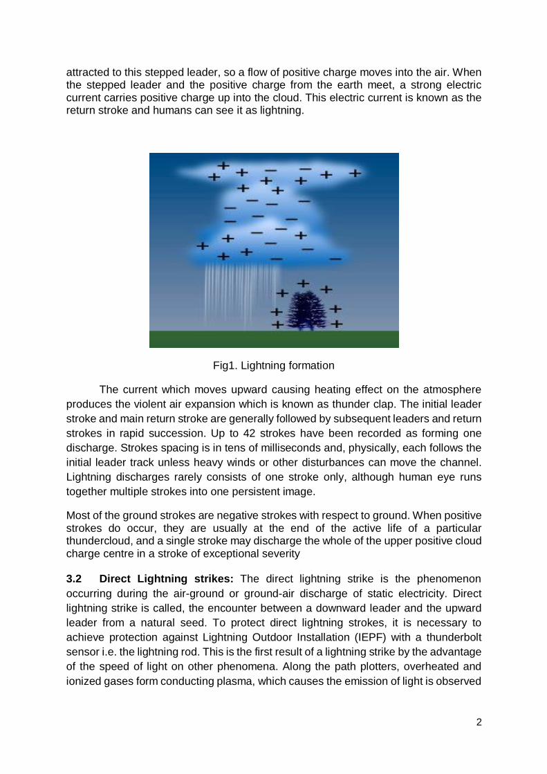
3.2 Direct Lightning strikes: The direct lightning strike is the phenomenon occurring during the air-ground or ground-air discharge of static electricity. Direct lightning strike is called, the encounter between a downward leader and the upward leader from a natural seed. To protect direct lightning strokes, it is necessary to achieve protection against Lightning Outdoor Installation (IEPF) with a thunderbolt sensor i.e. the lightning rod. This is the first result of a lightning strike by the advantage of the speed of light on other phenomena. Along the path plotters, overheated and ionized gases form conducting plasma, which causes the emission of light is observed
3
and which is called "flash". The color of this flash depends on factors such as current density, the viewing distance and the various particles present in the path of the tracer.
Fig 2 Direct strike out
3.3 The consequences of a direct lightning strike: Lightning is accompanied by an acoustic wave, the thunder. This wave is generated by the sudden expansion of the air overheated by the arc. It may consist of a snap or a deaf bearing according to listening distance. The duration of the thunder is a function of the size of the ionized path. These effects are related to the charge amounts involved during lightning strikes. They result in melting points more or less important in terms of impacts in the case of high resistivity materials. On bad driver’s materials (construction materials excluding metal), a large energy is released as heat and, while they contain moisture causes a sudden localized overpressure up to burst. By release of quantities of energy:
(i) The resistivity of the crossed materials is put into games. We witness these materials to deformation, broken away, destruction, explosions.
(ii) The proximity of metallic masses next to the descents drivers creates the
passage of lightning current, major efforts by the magnetic phenomenon of attraction / repulsion generated.
(iii) An electrolytic reaction in the materials (chemical decomposition) is likely to be
generated, however, the ephemeral nature of the lightning current makes a negligible phenomenon.
(iv) The electrical nature of the phenomenon and soil resistivity causes propagation
concentric waves of the lightning current into the ground and on the surface. The mounted potential of surrounding masses causes significant currents, where dangerous power lifts from the metal frames submitted.
(v) On current dissipation in soil, a phenomenon called step voltage can occur on
living beings. It causes burns, respiratory arrest, cardiac arrest. It is due to the spread of currents by contact being on the floor.
3.4 Indirect lightning strike: The indirect lightning strike is the result of a direct lightning strike unchecked. The resulting indirect lightning strike is called direct lightning strike whose flow is not controlled. While lightning current, the path would not be well channeled, can borrow any totally random way to reach the earth in its path
4
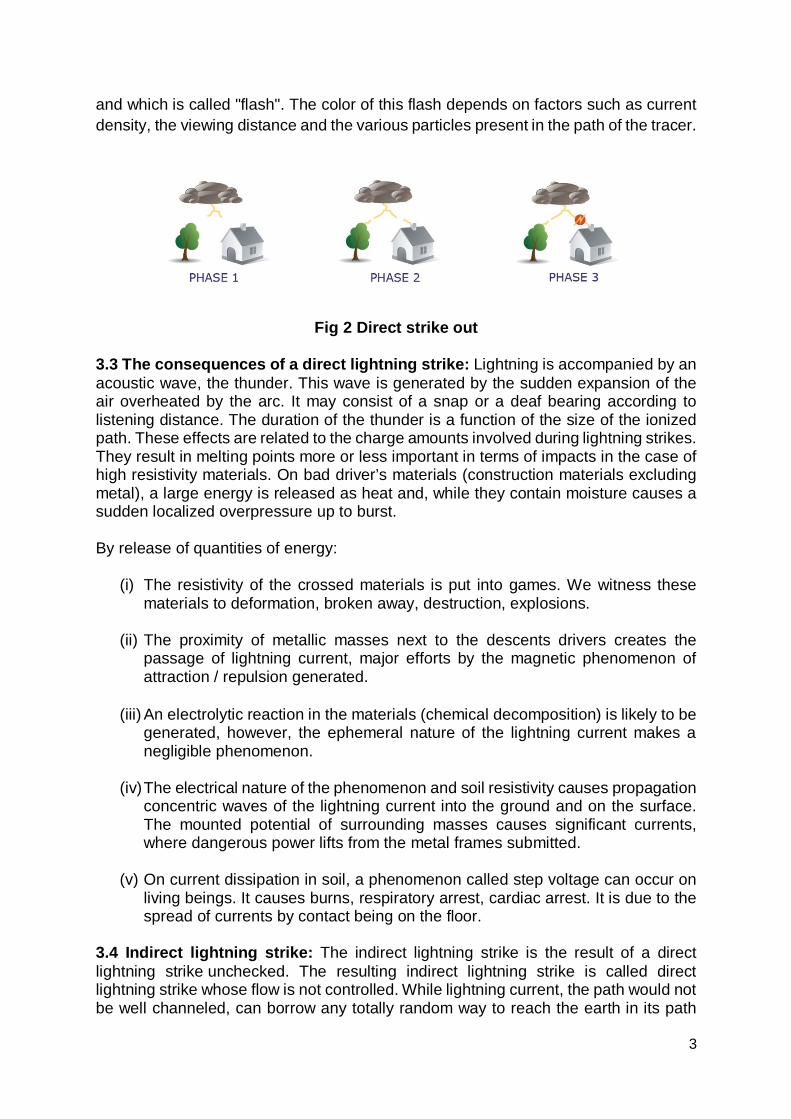
generating potential arcing (sparking). Surge (induced effects) appear between arrival outside power lines and the equi-potential system of land structure. These surges "penetrate" inwardly of the propagation structure (along the lines). Materials called Arresters are used and placed on the grid for this Protection.
Fig 3 Indirect strike out
3.5 Consequences of an indirect lightning strike: The surge phenomenon comes from direct contact with a conductive lightning. The overvoltage spreads along the conductor and network expansion. An electrical network or communication may contain the devastating power of Thunderbolt. The surge phenomenon comes from:
(i) The electromagnetic field radiated by the thunderbolt. Cables, conduits, antennas and all metal masses are likely to become conductors in a perimeter proportional to the power and speed of change of the lightning strike. (ii) The Electronic effects of direct lightning strike or dissipation of the lightning current discharged through the land of lightning to earth of the installation. The lightning current is likely to "turn back" the network by the land. (iii) The dispersion of current in the ground causing destructive potential differences between the masses of equipment and networks they are connected.
4.0 The Lightning risks: The study of the phenomenon highlights 3 large families of risks from lightning strikes: 4.1 Risks due to Direct lightning strike: The main feature of direct lightning strike is the flow of a huge electric current circulating in the matter causing extensive damage to structures.
The protection system against direct lightning consists of an outdoor installation of lightning conductor to protect against lightning strikes. 4.2 Risks due to Indirect lightning strikes: The power electric currents involved causes induced phenomena and electromagnetic fields that cause the destruction of electrical and electronic equipment. The protection system against indirect lightning consists of an indoor installation of protection to protect against lightning strikes.
5
4.3 Risks due to Conduction phenomena: During a lightning strike on the ground, we see that the electric charges are dissipated in the ground and create a rise of electric potential. The potential difference (voltage) between two given points in the ground or surface will allow current flow.
Lightning has many dangers and consequences of a lightning strike are
cumbersome (spectacular damage, made fires, destruction, explosions and sometimes death). To protect themselves, the implementation of a system of protection against lightning is needed.
5.0 Lightning protection (Direct and Indirect): The basic principle for protection of an installation against the risk of lightning strikes is to prevent the disturbing energy from reaching sensitive equipment. To achieve this, it is necessary to:
Capture the lightning current and channel it to earth via the most direct path (avoiding the vicinity of sensitive equipment);
Perform equi-potential bonding of the installation; This equi-potential bonding is implemented by bonding conductors, supplemented by Surge Protection Devices (SPDs) or spark gaps (e.g., antenna mast spark gap).
Minimize induced and indirect effects by installing SPDs and/or filters: Two protection systems are used to eliminate or limit over-voltages: they are known as the building protection system (for the outside of buildings) and the electrical installation protection system (for the inside of buildings).
5.1 Lightning protection system:
The role of the building protection system is to protect it against direct lightning strokes. The system consists of:
The capture device: the lightning protection system; Down-conductors designed to convey the lightning current to earth; "Crow's foot" earth leads connected together; Links between all metallic frames (equi-potential bonding) and the earth leads.
When the lightning current flows in a conductor, if potential differences appear between it and the frames connected to earth that are located in the vicinity, the latter can cause destructive flashovers.
6
5.2 Building Protection Systems: Three types of building protections are used
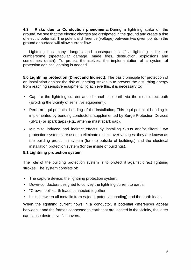
i) The lightning rod (simple rod or with triggering system)
The lightning rod is a metallic capture tip placed at the top of the building. It is earthed by one or more conductors (often copper strips) (see Fig. 4).
Fig.4: Lightning rod (simple rod or with triggering system)
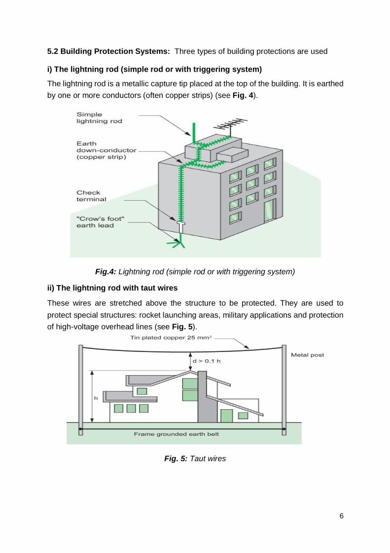
ii) The lightning rod with taut wires
These wires are stretched above the structure to be protected. They are used to protect special structures: rocket launching areas, military applications and protection of high-voltage overhead lines (see Fig. 5).
Fig. 5: Taut wires
7
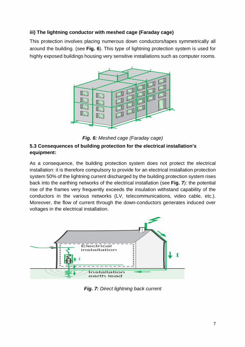
iii) The lightning conductor with meshed cage (Faraday cage)
This protection involves placing numerous down conductors/tapes symmetrically all around the building. (see Fig. 6). This type of lightning protection system is used for highly exposed buildings housing very sensitive installations such as computer rooms.
Fig. 6: Meshed cage (Faraday cage) 5.3 Consequences of building protection for the electrical installation’s equipment:
As a consequence, the building protection system does not protect the electrical installation: it is therefore compulsory to provide for an electrical installation protection system 50% of the lightning current discharged by the building protection system rises back into the earthing networks of the electrical installation (see Fig. 7): the potential rise of the frames very frequently exceeds the insulation withstand capability of the conductors in the various networks (LV, telecommunications, video cable, etc.). Moreover, the flow of current through the down-conductors generates induced over voltages in the electrical installation.
Fig. 7: Direct lightning back current
8
The main objective of the electrical installation protection system is to limit over-voltages to values that are acceptable for the equipment. The electrical installation protection system consists of:
One or more SPDs depending on the building configuration; The equi-potential bonding: metallic mesh of exposed conductive parts. The procedure to protect the electrical and electronic systems of a building is as follows:
Identify all sensitive loads and their location in the building. Identify the electrical and electronic systems and their respective points of entry
into the building. Check whether a lightning protection system is present on the building or in the
vicinity. Become acquainted with the regulations applicable to the building's location. Assess the risk of lightning strike according to the geographic location, type of
power supply, lightning strike density, etc.
Solution implementation
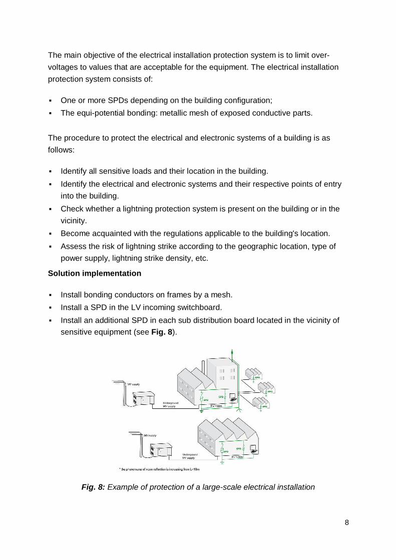
Install bonding conductors on frames by a mesh. Install a SPD in the LV incoming switchboard. Install an additional SPD in each sub distribution board located in the vicinity of
sensitive equipment (see Fig. 8).
Fig. 8: Example of protection of a large-scale electrical installation
9
6.0 Surges: If lightning strikes on or near overhead electric power or telephone line, a large current will be injected into or induced in the wires, and the current can do considerable damage both to the power and telecommunications equipment and to anything else that is connected to the system. Surges can have many effects on equipment, ranging from no detectable effect to complete destruction … electronic devices can have their operation upset before hard failure occurs. The semiconductor junctions of electronic devices are particularly susceptible to progressive deterioration; few solid state devices can tolerate much more than twice their normal rating. Furthermore, data processing equipment can be affected by fast changes in voltage with relatively small amplitude compared to the hardware-damaging over-voltages. For large surge currents, this diversion is best accomplished in several stages. The first diversion should be performed at the entrance to the building … a second protective device at the power panel.
6.1 A surge protector (or surge suppressor) is an appliance/device designed to protect electrical devices from voltage spikes. A surge protector attempts to limit the voltage supplied to an electric device by either blocking or by shorting to ground any unwanted voltages above a safe threshold. The terms surge protection device (SPD), or transient voltage surge suppressor (TVSS), are used to describe electrical devices typically installed in power distribution panels, process control systems, communications systems, and other heavy-duty industrial systems, for the purpose of protecting against electrical surges and spikes, including those caused by lightning.
Scaled-down versions of these devices are installed in residential service entrance electrical panels, to protect equipment in a household from similar hazards.
These are some of the most prominently featured specifications which define a surge protector for AC mains, as well as for some data communications protection applications.
6.2 Primary components: Systems used to reduce or limit high voltage surges can include one or more of the following types of electronic components:
The first six methods listed operate primarily by diverting unwanted surge energy away from the protected load, through a protective component connected in a parallel (or shunted) topology.
The last two methods also block unwanted energy by using a protective component connected in series with the power feed to the protected load, and additionally may shunt the unwanted energy like the earlier systems.
6.3 Parallel or shunted topology:
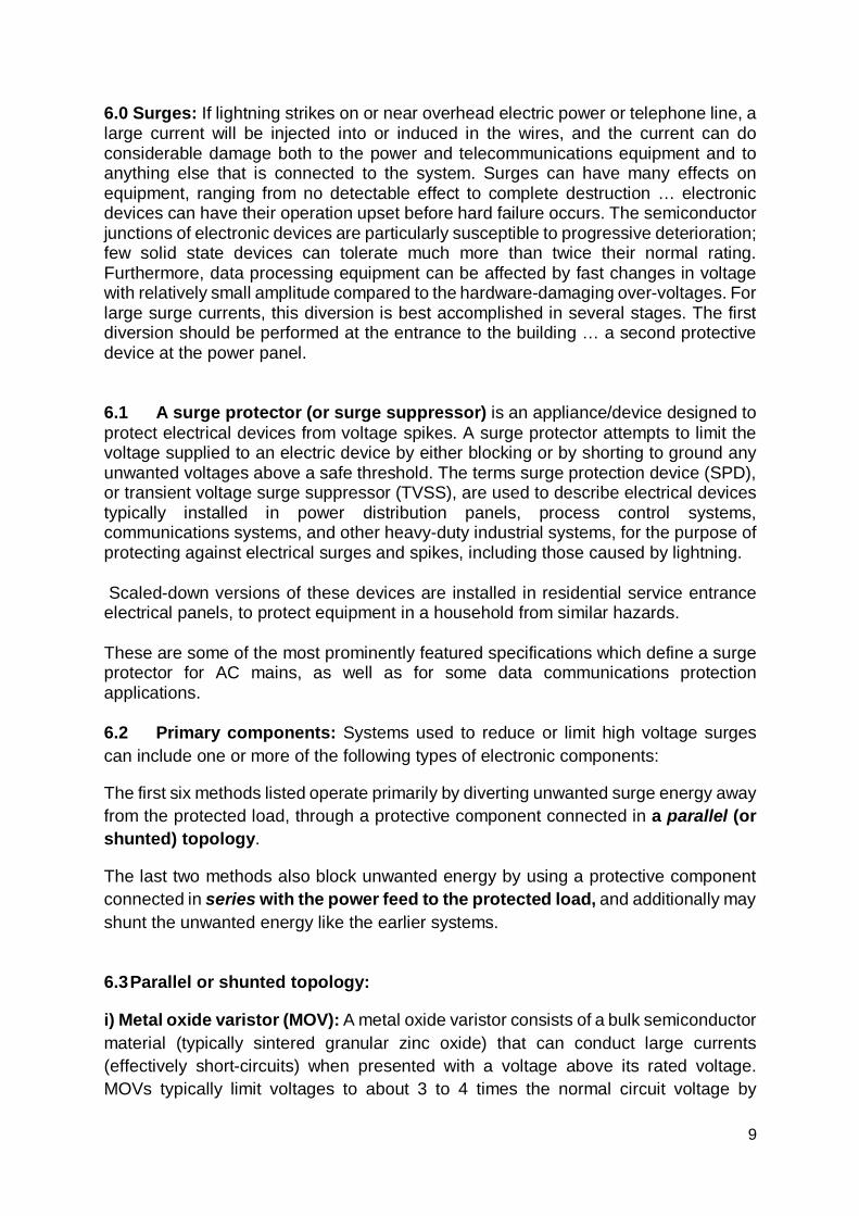
i) Metal oxide varistor (MOV): A metal oxide varistor consists of a bulk semiconductor material (typically sintered granular zinc oxide) that can conduct large currents (effectively short-circuits) when presented with a voltage above its rated voltage. MOVs typically limit voltages to about 3 to 4 times the normal circuit voltage by
10
diverting surge current elsewhere than the protected load. MOVs may be connected in parallel to increase current capability and life expectancy, providing they are matched sets (unmatched MOVs have a tolerance of approximately ±20% on voltage ratings, which is not sufficient).
ii) Transient voltage suppression (TVS) diode
A TVS diode is a type of Zener diode, also called an avalanche diode or silicon avalanche diode (SAD), which can limit voltage spikes. These components provide the fastest limiting action of protective components (theoretically in picoseconds), but have a relatively low energy absorbing capability. Voltages can be clamped to less than twice the normal operation voltage. If current impulses remain within the device ratings, life expectancy is exceptionally long. If component ratings are exceeded, the diode may fail as a permanent short circuit; in such cases, protection to their relatively limited current capacity, TVS diodes are often restricted to circuits with smaller current spikes.
iii) Thyristor surge protection device (TSPD)
A Trisil is a type of thyristor surge protection device (TSPD), a specialized solid-state electronic device used in crowbar circuits to protect against overvoltage conditions. A SIDAC tor is another thyristor type device used for similar protective purposes. These thyristor-family devices can be viewed as having characteristics much like a spark gap or a GDT, but can operate much faster. They are related to TVS diodes, but can "break over" to a low clamping voltage analogous to an ionized and conducting spark gap. After triggering, the low clamping voltage allows large current surges to flow while limiting heat dissipation in the device.
A gas discharge tube (GDT) is a sealed glass-enclosed device containing a special gas mixture trapped between two electrodes, which conducts electric current after becoming ionized by a high voltage spike. GDTs can conduct more current for their size than other components. Like MOVs, GDTs have a finite life expectancy, and can handle a few very large transients or a greater number of smaller transients. The typical failure mode occurs when the triggering voltage rises so high that the device becomes ineffective, although lightning surges can occasionally cause a dead short.
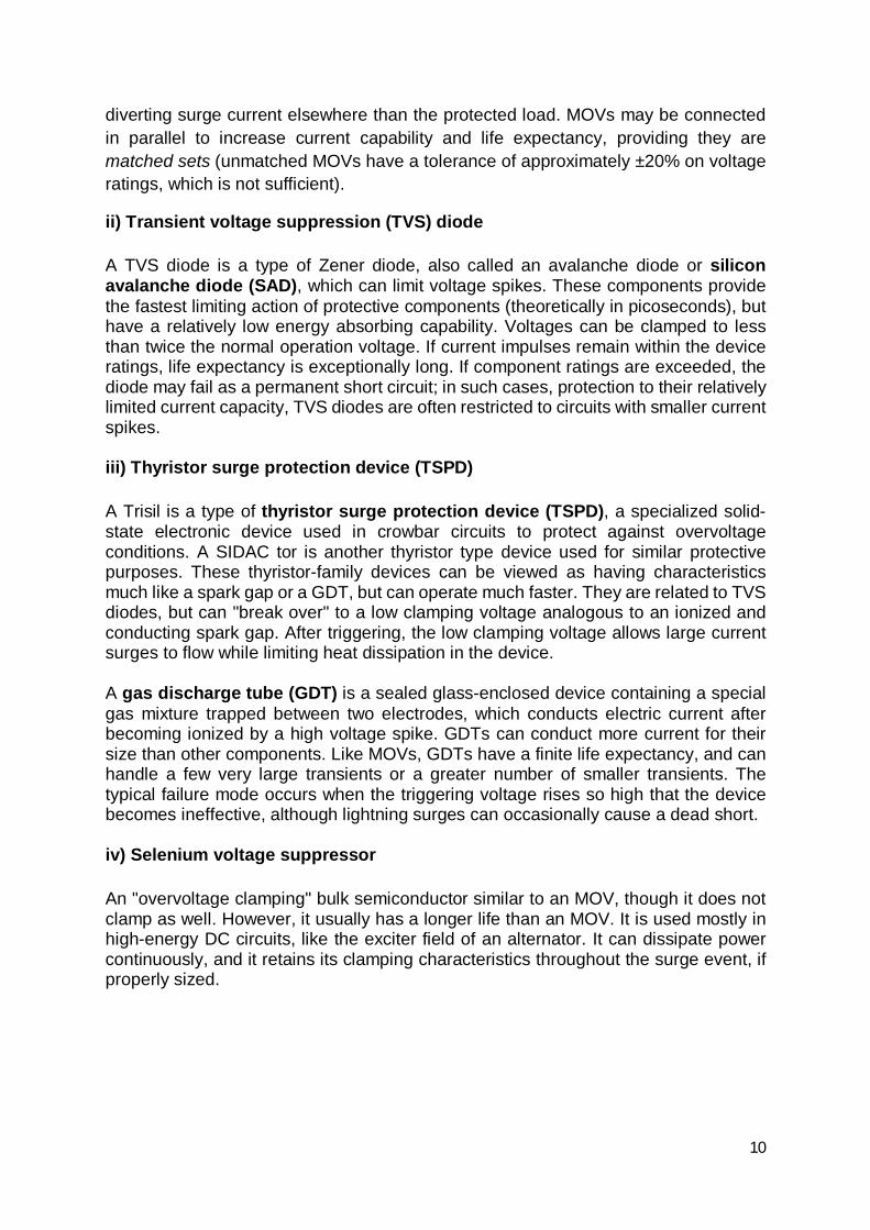
iv) Selenium voltage suppressor
An "overvoltage clamping" bulk semiconductor similar to an MOV, though it does not clamp as well. However, it usually has a longer life than an MOV. It is used mostly in high-energy DC circuits, like the exciter field of an alternator. It can dissipate power continuously, and it retains its clamping characteristics throughout the surge event, if properly sized.
11
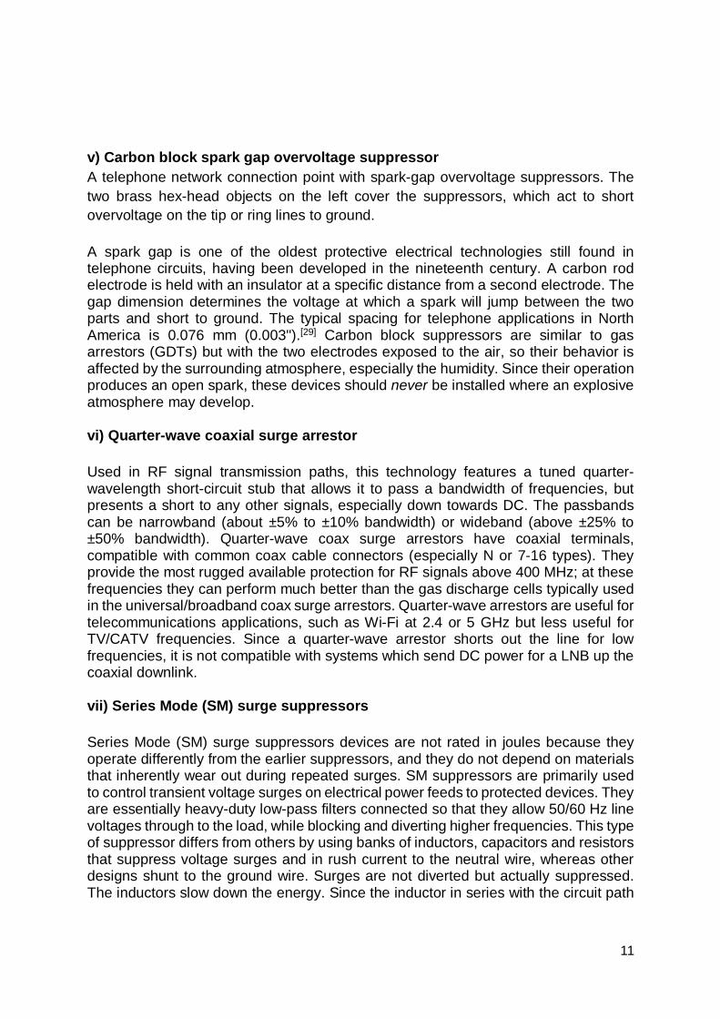
v) Carbon block spark gap overvoltage suppressor A telephone network connection point with spark-gap overvoltage suppressors. The two brass hex-head objects on the left cover the suppressors, which act to short overvoltage on the tip or ring lines to ground.
A spark gap is one of the oldest protective electrical technologies still found in telephone circuits, having been developed in the nineteenth century. A carbon rod electrode is held with an insulator at a specific distance from a second electrode. The gap dimension determines the voltage at which a spark will jump between the two parts and short to ground. The typical spacing for telephone applications in North America is 0.076 mm (0.003").[29] Carbon block suppressors are similar to gas arrestors (GDTs) but with the two electrodes exposed to the air, so their behavior is affected by the surrounding atmosphere, especially the humidity. Since their operation produces an open spark, these devices should never be installed where an explosive atmosphere may develop.
vi) Quarter-wave coaxial surge arrestor
Used in RF signal transmission paths, this technology features a tuned quarter-wavelength short-circuit stub that allows it to pass a bandwidth of frequencies, but presents a short to any other signals, especially down towards DC. The passbands can be narrowband (about ±5% to ±10% bandwidth) or wideband (above ±25% to ±50% bandwidth). Quarter-wave coax surge arrestors have coaxial terminals, compatible with common coax cable connectors (especially N or 7-16 types). They provide the most rugged available protection for RF signals above 400 MHz; at these frequencies they can perform much better than the gas discharge cells typically used in the universal/broadband coax surge arrestors. Quarter-wave arrestors are useful for telecommunications applications, such as Wi-Fi at 2.4 or 5 GHz but less useful for TV/CATV frequencies. Since a quarter-wave arrestor shorts out the line for low frequencies, it is not compatible with systems which send DC power for a LNB up the coaxial downlink.
vii) Series Mode (SM) surge suppressors
Series Mode (SM) surge suppressors devices are not rated in joules because they operate differently from the earlier suppressors, and they do not depend on materials that inherently wear out during repeated surges. SM suppressors are primarily used to control transient voltage surges on electrical power feeds to protected devices. They are essentially heavy-duty low-pass filters connected so that they allow 50/60 Hz line voltages through to the load, while blocking and diverting higher frequencies. This type of suppressor differs from others by using banks of inductors, capacitors and resistors that suppress voltage surges and in rush current to the neutral wire, whereas other designs shunt to the ground wire. Surges are not diverted but actually suppressed. The inductors slow down the energy. Since the inductor in series with the circuit path
12
slows the current spike, the peak surge energy is spread out in the time domain and harmlessly absorbed and slowly released from a capacitor bank.
Experimental results show that most surge energies occur at under 100 Joules, so exceeding the SM design parameters is unlikely. SM suppressors do not present a fire risk should the absorbed energy exceed design limits of the dielectric material of the components because the surge energy is also limited via arc-over to ground during lightning strikes, leaving a surge remnant that often does not exceed a theoretical maximum (such as 6000 V at 3000 A with a modeled shape of 8 x 20 microsecond waveform specified by IEEE/ANSI C62.41). Because SM work on both the current rise and the voltage rise, they can safely operate in the worst surge environments.
SM suppression focuses its protective philosophy on a power supply input, but offers nothing to protect against surges appearing between the input of an SM device and data lines, such as antennae, telephone or LAN connections, or multiple such devices cascaded and linked to the primary devices. This is because they do not divert surge energy to the ground line. Data transmission requires the ground line to be clean in order to be used as a reference point. In this design philosophy, such events are already protected against by the SM device before the power supply. NIST reports that "Sending them [surges] down the drain of a grounding conductor only makes them reappear within a microsecond about 200 meters away on some other conductor." So having protection on a data transmission line is only required if surges are diverted to the ground line.
In comparison to devices relying on 10 cent components that operate only briefly (such as MOVs or GDTs), SM devices tend to be bulkier and heavier than those simpler spike shunting components. The initial costs of SM filters are higher, typically 130 USD and up, but a long service life can be expected if they are used properly. In-field installation costs can be higher, since SM devices are installed in series with the power feed, requiring the feed to be cut and reconnected.
Specifications:
Clamping voltage: This specifies what spike voltage will cause the protective components inside a surge protector to divert unwanted energy from the protected line. A lower clamping voltage indicates better protection, but can sometimes result in a shorter life expectancy for the overall protective system.
Joules rating: This number defines how much energy an MOV-based surge protector can theoretically absorb in a single event, without failure. Counter-intuitively, a lower number may indicate longer life expectancy if the device can divert more energy elsewhere and thus absorb less energy. In other words, a protective device offering a lower clamping voltage while diverting the same surge current will cause more of the surge energy to be dissipated elsewhere in that current's path.
13
Response time: Surge protectors don't operate instantaneously; a slight delay exists. The longer the response time, the longer the connected equipment will be exposed to the surge. However, surges don't happen instantly either. Surges usually take around a few microseconds to reach their peak voltage, and a surge protector with a nanosecond response time would kick in fast enough to suppress the most damaging portion of the spike.
Standards: Some frequently listed standards include.
IEC 61000-4-5: Lightning and industrial surges modeled by IEC 61000-4-5
• Test levels 0.5 kV, 1.0 kV, 2.0 kV, 4.0 kV and X kV • Test circuit and waveform 1.2/50 µs at 2 Ω • Telecommunication lines are exposed to lightning either directly on the
equipment or due to induced effect because of ground potential change. • In addition to these surges, a telecommunication line may also be disturbed by
either power induction or power contact with main AC lines. Depending on the country, these surges have been mainly modeled in:
Telecordia GR-1089
• Telecordia GR-1089 core for America with 2/10 µs and 10/1000 µs surge
ITU K.20 and .21: Series for the rest of the world with 10/700 µs surges
• K20 • Test levels 1.0 kV, 1.5 kV, 4.0 kV, 6.0 kV along = 25 Ω resistance • Test circuit and waveform 10/700 µs
• K.21 1.5 kV, 4.0 kV, and 6.0 kV along = 25 Ω resistance • Test circuit and waveform 10/700 µs
The other standards being followed are:
• TIA-968-A/B • UL/EN/IEC 60950-1 • UL497B • YD/T-950-based on ITU K.20 • YD/T-993-based on ITU K.21
Each standard defines different protector characteristics, test vectors, or operational purpose.
8.0 Difference between lightning protection and surge protection: The lightning and surge protection are hardware protection against lightning with different functionalities to the phenomenon of the lightning strike.
14
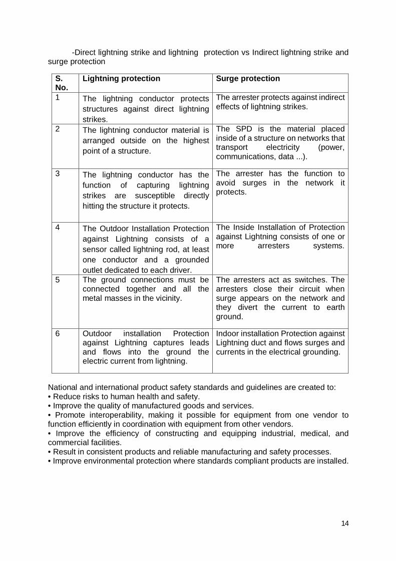
-Direct lightning strike and lightning protection vs Indirect lightning strike and surge protection
S. No.
Lightning protection Surge protection
1 The lightning conductor protects structures against direct lightning strikes.
The arrester protects against indirect effects of lightning strikes.
2 The lightning conductor material is arranged outside on the highest point of a structure.
The SPD is the material placed inside of a structure on networks that transport electricity (power, communications, data ...).
3 The lightning conductor has the function of capturing lightning strikes are susceptible directly hitting the structure it protects.
The arrester has the function to avoid surges in the network it protects.
4 The Outdoor Installation Protection against Lightning consists of a sensor called lightning rod, at least one conductor and a grounded outlet dedicated to each driver.
The Inside Installation of Protection against Lightning consists of one or more arresters systems.
5 The ground connections must be connected together and all the metal masses in the vicinity.
The arresters act as switches. The arresters close their circuit when surge appears on the network and they divert the current to earth ground.
6 Outdoor installation Protection against Lightning captures leads and flows into the ground the electric current from lightning.
Indoor installation Protection against Lightning duct and flows surges and currents in the electrical grounding.
National and international product safety standards and guidelines are created to: • Reduce risks to human health and safety. • Improve the quality of manufactured goods and services. • Promote interoperability, making it possible for equipment from one vendor to function efficiently in coordination with equipment from other vendors. • Improve the efficiency of constructing and equipping industrial, medical, and commercial facilities. • Result in consistent products and reliable manufacturing and safety processes. • Improve environmental protection where standards compliant products are installed.
15
9. Electrical Ground System: An electrical ground system may be described as a system in which at least one conductor or point is intentionally grounded to the earth in a manner that limits the voltage imposed by lightning, line surges, or unintentional contact with a higher voltage line and will act to stabilize the voltage to earth during normal operation. The importance of designing and testing electrical ground systems includes:
Equalization of the potential of conductive parts; Personal Safety Promotes optimal performance of over-current protection devices Mitigation of lightning strike damages Necessary for reliable Surge Protection Device (SPD) operation Dissipation of electrical transients Reduction of electromagnetic interference Required to meet local codes and design requirements An electrical ground system is comprised of following four major sub systems:
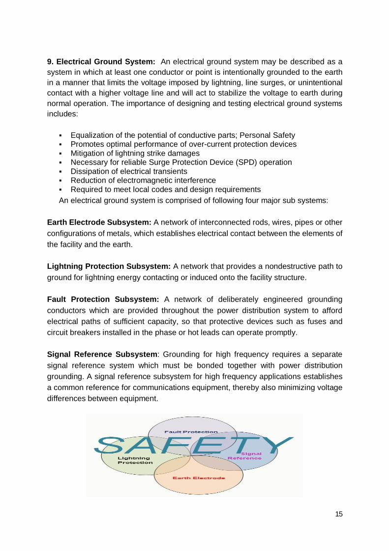
Earth Electrode Subsystem: A network of interconnected rods, wires, pipes or other configurations of metals, which establishes electrical contact between the elements of the facility and the earth. Lightning Protection Subsystem: A network that provides a nondestructive path to ground for lightning energy contacting or induced onto the facility structure. Fault Protection Subsystem: A network of deliberately engineered grounding conductors which are provided throughout the power distribution system to afford electrical paths of sufficient capacity, so that protective devices such as fuses and circuit breakers installed in the phase or hot leads can operate promptly. Signal Reference Subsystem: Grounding for high frequency requires a separate signal reference system which must be bonded together with power distribution grounding. A signal reference subsystem for high frequency applications establishes a common reference for communications equipment, thereby also minimizing voltage differences between equipment.
16
Fig 9 Safety is Prime Concern
Types of Grounding
Lightning Protection Grounding
Static Protection Grounding
AC System Grounding
Equipment Grounding
DC System Grounding
Noise Grounding
EMI/RFI Grounding
Earth Grounding
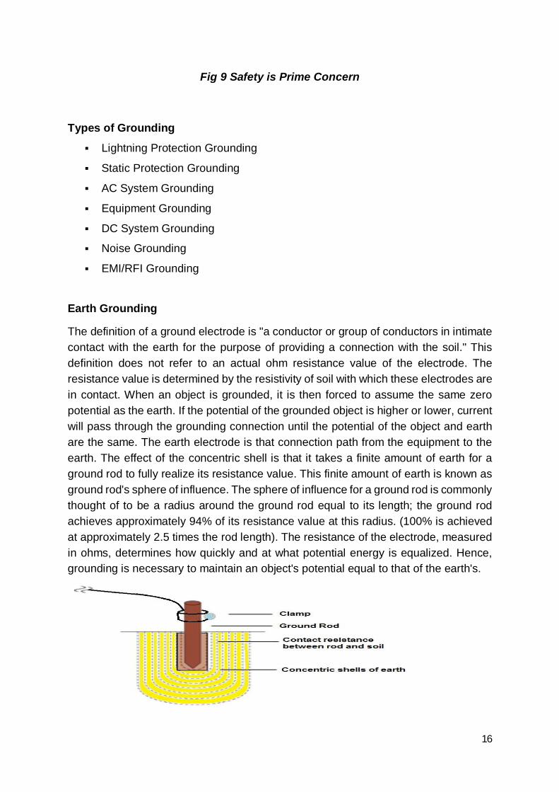
The definition of a ground electrode is "a conductor or group of conductors in intimate contact with the earth for the purpose of providing a connection with the soil." This definition does not refer to an actual ohm resistance value of the electrode. The resistance value is determined by the resistivity of soil with which these electrodes are in contact. When an object is grounded, it is then forced to assume the same zero potential as the earth. If the potential of the grounded object is higher or lower, current will pass through the grounding connection until the potential of the object and earth are the same. The earth electrode is that connection path from the equipment to the earth. The effect of the concentric shell is that it takes a finite amount of earth for a ground rod to fully realize its resistance value. This finite amount of earth is known as ground rod's sphere of influence. The sphere of influence for a ground rod is commonly thought of to be a radius around the ground rod equal to its length; the ground rod achieves approximately 94% of its resistance value at this radius. (100% is achieved at approximately 2.5 times the rod length). The resistance of the electrode, measured in ohms, determines how quickly and at what potential energy is equalized. Hence, grounding is necessary to maintain an object's potential equal to that of the earth's.
17
Figure 10: Sphere of Influence
Conclusion: These surges can also enter the premises via internet cable and telecommunications lines. However, numerous studies have shown that exterior sources account for only 20 percent of all electrical surges. The remaining 80 percent can be accounted for by culprits within a network. Known sources of transients and noise within a building or network include everyday things such as fax machines, copiers, air conditioners, elevators, motors/ pumps, or arc welders, to name a few. In each case, the normal electric circuit is suddenly exposed to a large dose of energy that can adversely affect the equipment being supplied power. Although surges and electrical noise can’t be totally eliminated, they can be mitigated through an engineered approach, thereby reducing their damaging effect. This leads to greater reliability and overall improved productivity. In this regard, surge protection really is an inexpensive form of electrical system insurance.


![Version 4.0 (January 6, 2009) arXiv:0707.1161v4 [physics.ao-ph] 4 … · 2009-03-04 · is still supported in global climatology, essentially describes a ctitious mechanism, in which](https://img.pdfslide.net/doc/110x75/5e5cdf46914b8e00bc07b448/version-40-january-6-2009-arxiv07071161v4-4-2009-03-04-is-still-supported.jpg)