Embed Size (px)
Citation preview
U.S. Department of Transportation Federal Aviation Administration
Advisory Circular
Subject: Authorization of Aircraft and Operators for Flight in Reduced Vertical Separation Minimum Airspace
Date: 8/21/09
Initiated by: AFS-470
AC No: 91–85
Change:
1. PURPOSE. This advisory circular (AC) contains information on airworthiness, continuing airworthiness, and operations programs for Reduced Vertical Separation Minimum (RVSM) operations. RVSM airspace is any airspace or route between flight level (FL) 290 and FL 410 inclusive where aircraft are separated vertically by 1,000 ft (300 m). This AC is not mandatory and does not constitute a regulation. This AC describes an acceptable means, but not the only means, for authorization of aircraft and operators to conduct flight in airspace or on routes where RVSM is applied.
2. APPLICABILITY. This AC applies to operators who want to apply for authorization to conduct operations in RVSM airspace.
3. CANCELLATION. This AC replaces Guidance Document 91-RVSM, which provided guidance on aircraft and operators’ approval for operating in RVSM airspace. (The guidance document was located on the RVSM Web site at http://www.faa.gov/about/office_org/headquarters_offices/ato/service_units/enroute/rvsm/documents/91RVSM_Chg2_Feb_1004.doc.)
4. RELATED CFR SECTIONS. Title 14 of the Code of Federal Regulations (14 CFR):
• Part 43.
• Part 91, §§ 91.180, 91.411, 91.705, 91.706, and appendix G.
• Part 121.
• Part 129.
• Part 135.
• Part 145.
5. RELATED READING MATERIAL.
• Federal Aviation Administration (FAA) Aeronautical Information Manual (AIM).
AC 91-85 8/21/09
Page 2 Par 5
• FAA Order 8900.1, Flight Standards Information Management System (FSIMS).
• FAA RVSM Documentation Web site http://www.faa.gov/about/office_org/headquarters_offices/ato/service_units/enroute/rvsm/.
• International Civil Aviation Organization (ICAO) Document 4444, Procedures for Air Navigation Services, Air Traffic Management.
• ICAO Annex 6, Operation of Aircraft. Part I—International Commercial Air Transport—Aeroplanes and Part II—International General Aviation—Aeroplanes.
• ICAO Document 7030, Regional Supplementary Procedures.
• ICAO Document 9574, Manual on Implementation of a 300 m (1000 ft) Vertical Separation Minimum Between FL 290 and FL 410 Inclusive.
6. DEFINITIONS.
a. Aircraft Group. A group of aircraft of nominally identical design and build with respect to all details that could influence the accuracy of height-keeping performance. (See paragraph 9b(2)).
b. Altimetry System Error (ASE). The difference between the pressure altitude displayed to the flightcrew when referenced to International System of Units (SI) standard ground pressure setting (29.92 in. Hg/1013.25 hPa) and free stream pressure altitude.
c. Assigned Altitude Deviation (AAD). The difference between the transponded Mode C altitude and the assigned altitude/flight level.
d. Automatic Altitude Control System. Any system designed to automatically control the aircraft to a referenced pressure altitude.
e. Avionics Error. The error in the processes of converting the sensed pressure into an electrical output, of applying any static source error correction (SSEC) as appropriate, and of displaying the corresponding altitude.
f. Basic RVSM Envelope. The range of Mach numbers and gross weights within the altitude ranges FL 290 to FL 410 (or max available altitude) where an aircraft is expected to operate most frequently. (See paragraph 9b(4)(b).)
g. Full RVSM Envelope. The entire range of operational Mach numbers, W/δ, and altitude values over which the aircraft is operated within RVSM airspace (see paragraph 9b(4)(a)).
h. Height-Keeping Capability. Aircraft height-keeping performance expected under nominal environmental operating conditions with proper aircraft operating practices and maintenance.
8/21/09 AC 91-85
i. Height-Keeping Performance. The observed performance of an aircraft with respect to adherence to a flight level.
j. Non-Group Aircraft. An aircraft for which the operator applies for approval on the characteristics of the unique airframe rather than on a group basis (see paragraph 10b(3)).
k. Residual Static Source Error (SSE). The amount by which static source error (SSE) remains undercorrected or overcorrected after the application of SSEC.
l. SSE. The difference between the pressure sensed by the static system at the static port and the undisturbed ambient pressure.
m. SSEC. A correction for SSE.
n. Total Vertical Error (TVE). Vertical geometric difference between the actual pressure altitude flown by an aircraft and its assigned pressure altitude (FL).
o. W/δ. Aircraft weight, W, divided by the atmospheric pressure ratio, δ.
7. AUTHORIZATION/APPROVAL PROCESS.
a. General. Airspace where RVSM is a special navigation area of operation. Both the individual operator and the specific aircraft type or types which the operator intends to use should be authorized by the appropriate FAA offices before the operator conducts flight operations in RVSM airspace. This document provides guidance for aircraft and operator authorization to meet the requirements of § 91.180, Operations within airspace designated as Reduced Vertical Separation Minimum airspace; § 91.706, Operations within airspace designated as Reduced Vertical Separation Minimum Airspace; and appendix G, Operations in Reduced Vertical Separation Minimum (RVSM) Airspace.
b. Approval of Aircraft. Each aircraft type that an operator intends to use in RVSM airspace should have received FAA approval in accordance with paragraph 9 before the operational authorization will be granted.
(1) In-service Aircraft: Parts 121, 125, and 135 Operations. Aircraft manufacturers should coordinate with the appropriate Aircraft Certification Office (ACO) to determine the process and procedures for RVSM airworthiness approval. An individual operator seeking approval for its aircraft should contact the manufacturer of the specific aircraft type and the operator’s assigned certificate management office (CMO) or the Flight Standards District Office (FSDO) which holds their operating certificate to determine/coordinate the process for RVSM authorization. Final authorization will require coordination between the operator, the CMO or FSDO, the ACO, and the aircraft manufacturer or design organization.
(2) In-service Aircraft: Part 91 Operations. An aircraft manufacturer should contact the assigned ACO to determine the process and procedures for RVSM airworthiness approval. An individual operator seeking approval for its aircraft should contact the manufacturer of the specific aircraft type and the local FSDO to determine/coordinate the process for RVSM approval.
Par 6 Page 3
AC 91-85 8/21/09
Page 4 Par 7
(3) New Build Aircraft. A manufacturer that desires to have a specific aircraft type approved for RVSM operations should contact the appropriate ACO within its assigned geographical area. Manufacturers will be able to receive airworthiness approval only.
(4) Part 129. For RVSM operations conducted within the United States under part 129, aircraft should be approved by the state of the operator and/or registry. In some cases, the State of the Operator may be different from the State of Registry.
c. Operator Authorization. Paragraph 9 provides guidance for obtaining initial airworthiness approval for RVSM operations. Paragraph 10 contains guidance on the continuous airworthiness (maintenance) programs for RVSM operations. Paragraph 11 contains guidance on the operational procedures and programs that an operator should adopt for RVSM operation. Each individual operator should plan to present these programs to the FAA at least 60 days before commencing the proposed operation. Paragraph 11 also discusses the timing, process, maintenance, and operations material that the operator should submit for FAA review and evaluation. The appropriate FAA offices to contact to begin the process are as follows:
(1) Parts 91 subpart K (part 91K), 121, 125, and 135 operators should notify the jurisdictional certificate-holding district office (CHDO), CMO, or FSDO of its intent to obtain authorization for RVSM operations. The operator can expect the CHDO/CMO/FSDO to consult Order 8900.1, Volume 4, Chapter 1, Section 5, Special Navigation Areas of Operation and Chapter 10, Section 1, Evaluate Operator’s Application to Conduct Flight in Reduced Vertical Separation Minimums Airspace, and the FAA RVSM documentation Web site (http://www.faa.gov/about/office_org/headquarters_offices/ato/service_units/enroute/rvsm/) for guidance on RVSM authorization and sources of technical assistance.
(2) Part 91 operators should contact their local FSDO to start the process to receive a letter of authorization (LOA), which will grant authorization for RVSM operations. The operator can expect the FSDO to consult Order 8900.1, volume 4, chapter 1, section 5 and chapter 10, section 1 and the FAA RVSM documentation Web site at http://www.faa.gov/about/office_org/headquarters_offices/ato/service_units/enroute/rvsm/, as necessary for guidance on RVSM authorization and sources of technical assistance
NOTE: If the operator relocates its principal base of operations (address), it must notify, in writing, the losing FSDO of the new location and mailing address within 30 calendar-days following relocation and inform the losing FSDO of the receiving FSDO where the operator proposes to do business.
(3) A part 129 operations specification (OpSpec) paragraph is issued for operators conducting RVSM operations under a part 129 certificate. (See Order 8900.1, Volume 12, International Aviation.)
8. RVSM PERFORMANCE.
a. General. The statistical performance statements of ICAO Doc. 9574 for a population of aircraft (see Appendix 6) are translated into airworthiness standards by assessment of the characteristics of ASE and altitude control. The following standards differ in some respects from that document, but they are consistent with the requirements of RVSM.
8/21/09 AC 91-85
b. RVSM Flight Envelopes. For the purposes of RVSM approval, the aircraft flight envelope is considered in two parts: 1) the basic RVSM envelope, and 2) the full RVSM envelope. (The parameters for these envelopes are detailed in paragraph 9b(4).) The basic RVSM envelope is the part of the flight envelope where aircraft operate the majority of time. The full RVSM envelope includes parts of the flight envelope where the aircraft operates less frequently and where a larger ASE tolerance is allowed. (See paragraphs 7c(3) and 7c(4).)
c. ASE.
(1) In order to evaluate a system against the ASE performance statements established by the Review of the General Concept of Separation Panel (RGCSP) (see Appendix 6, paragraph 3), it is necessary to quantify the mean and three standard deviation (SD) values for ASE, expressed as ASEmean and ASE3 SD. In order to do this, it is necessary to account for the different ways in which variations in ASE can arise. The factors that affect ASE are as follows:
(a) Unit to unit variability of avionics.
(b) Effect of environmental operating conditions on avionics.
(c) Airframe to airframe variability of SSE.
(d) Effect of flight operating condition on SSE.
NOTE: ASE should contain a statement of pressure transducer drift from the manufacturer to accommodate how much the ASE is expected to drift.
(2) Assessment of ASE, whether based on measured or predicted data must include the factors listed above in subparagraphs 7c(1)(a) through 7c(1)(d). The effect of item (d) as a variable can be eliminated by evaluating ASE at the most adverse flight condition in an RVSM flight envelope.
(3) The requirements in the basic RVSM envelope are as follows:
(a) At the point in the basic RVSM envelope where ASEmean reaches its largest absolute value, the absolute value should not exceed 80 ft (25 m).
(b) At the point in the basic RVSM envelope where ASEmean plus ASE3 SD reaches its largest absolute value, the absolute value should not exceed 200 ft (60 m).
(4) The requirements in the full RVSM envelope are as follows:
(a) At the point in the full RVSM envelope where ASEmean reaches its largest absolute value, the absolute value should not exceed 120 ft (37 m).
(b) At the point in the full RVSM envelope where ASEmean plus of ASE3 SD reaches its largest absolute value, the absolute value should not exceed 245 ft (75 m).
Par 8 Page 5
AC 91-85 8/21/09
Page 6 Par 8
(c) If necessary, for the purpose of achieving RVSM approval for an aircraft group, an operating restriction may be established to restrict aircraft from conducting RVSM operations in areas of the full RVSM envelope where the absolute value of ASEmean exceeds 120 ft (37 m) and/or the absolute value of ASEmean plus ASE3 SD exceed 245 ft (75 m).
NOTE: When such a restriction is established, identify it in the data package and document it in appropriate aircraft operating manuals; however, visual or aural warning/indication systems should not be required to be installed on the aircraft.
(5) Aircraft types for which application for type certification or major change in type design is made after April 9, 1997, should meet the criteria established for the basic envelope in the full RVSM envelope. (See paragraph 8c(3).) The FAA will consider factors that provide an equivalent level of safety in the application of this criteria as stated in part 21, § 21.21b(1).
(6) The requirement of ICAO Doc. 9574 that each individual aircraft in the group should be built to have ASE contained within ±200 ft (±60 m) is discussed in paragraph 10b(5)(d)6.
(7) The standards of paragraphs 8c(3), 8c(4) and 8c(5) cannot be applied to non-group aircraft approval because there can be no group data with which to develop airframe to airframe variability. Therefore, a single ASE value has been established that controls the simple sum of the altimetry system errors. In order to control the overall population distribution, this limit has been set at a value less than that for group approval.
(8) The standard for aircraft submitted for approval as non-group aircraft, as defined in paragraph 9b(3), is as follows:
(a) For all conditions in the basic RVSM envelope:
( )m50ft160avionicscaseworstSSEsidualRe ≤+
(b) For all conditions in the full RVSM envelope:
( )m60ft200avionicscaseworstSSEsidualRe ≤+
NOTE: Worst-case avionics means that combination of tolerance values, specified by the manufacturer for the altimetry fit into the aircraft, which gives the largest combined absolute value for residual SSE plus avionics errors. For some systems, this may not be a fixed value over time.
d. Altitude Keeping. An automatic altitude control system should be required, and it should be capable of controlling altitude within ±65 ft (±20 m) about the acquired altitude when operated in straight and level flight under nonturbulent, nongust conditions.
NOTE: Aircraft types for which application for type certification or major change in type design is made on or before April 9, 1997, which are equipped with automatic altitude control systems with flight management
8/21/09 AC 91-85
system(FMS)/performance management system inputs allowing variations up to ±130 ft (±40 m) under nonturbulent, nongust conditions do not require retrofit or design alteration.
9. AIRCRAFT SYSTEMS.
a. Equipment for RVSM Operations. The minimum equipment fit should be as follows:
(1) Two Independent Altitude Measurement Systems. Each system should be composed of the following elements:
(a) Cross-coupled static source/system, provided with ice protection if located in areas subject to ice accretion;
(b) Equipment for measuring static pressure sensed by the static source, converting it to pressure altitude and displaying the pressure altitude to the flightcrew;
(c) Equipment for providing a digitally coded signal corresponding to the displayed pressure altitude, for automatic altitude reporting purposes;
(d) SSEC, if needed to meet the performance requirements of paragraphs 8c(3) and 8c(4), or 8c(8), as appropriate; and
(e) The equipment fit should provide reference signals for automatic control and alerting at selected altitude. These signals should preferably be derived from an altitude measurement system meeting the full requirements of this document, but must in all cases meet the requirements of paragraphs 9b(6) and 9c. (See Appendix 7 for additional guidance for configurations found on older model “legacy” airplanes for which RVSM approval is sought.)
(2) One Secondary Surveillance Radar (SSR) Altitude Reporting Transponder. If only one is fitted, it should have the capability for switching to obtain input from either altitude measurement system.
(3) An Altitude Alert System. The altitude alert system should be capable of operation from either of the two required independent altitude measurement systems.
(4) An Automatic Altitude Control System. The automatic altitude control system should be capable of operation from either of the two required independent altitude measurement systems.
b. Altimetry.
(1) The altimetry system of an aircraft comprises all those elements involved in the process of sampling free stream static pressure and converting it to a pressure altitude output. The elements of the altimetry system fall into two main groups:
(a) Airframe plus static sources, including the area around the static sources in the system design that must be maintained.
Par 8 Page 7
AC 91-85 8/21/09
Page 8 Par 9
(b) Avionics and/or instruments.
(2) The following altimetry system outputs are significant for RVSM operations:
(a) Pressure altitude (Baro Corrected) display, including the area around the static sources in the system design that must be maintained.
(b) Pressure altitude reporting data.
(c) Pressure altitude or pressure altitude deviation for an automatic altitude control device.
(3) The total altimetry system accuracy should satisfy the requirements of paragraphs 8c(3) and 8c(4), or 8c(8), as appropriate.
(4) If the design and characteristics of the aircraft and altimetry system are such that the standards of paragraphs 8c(3) and 8c(4), or 8c(8), are not satisfied by the location and geometry of the static sources alone, then suitable SSEC should be applied automatically within the avionic part of the altimetry system. The design aim for SSEC, whether aerodynamic/geometric or avionic, should be to produce a minimum residual SSE, but in all cases it should lead to satisfaction of the standards of paragraphs 8c(3) and 8c(4), or 8c(8), as appropriate.
(5) The aircraft altimetry system should provide an output to the aircraft transponder in accordance with regulations of the approving authority.
(6) The altimetry system will provide an output that an automatic altitude control system can use to control the aircraft at a commanded altitude. The output may be used either directly or combined with other sensor signals. If SSEC is necessary in order to satisfy the requirements of paragraphs 8c(3) and 8c(4), or 8c(8), then an equivalent SSEC must be applied to the altitude control output. The output may be an altitude deviation signal, relative to the selected altitude, or a suitable absolute altitude output. Whatever the system architecture and SSEC system, the difference between the output to the altitude control system and the altitude displayed must be minimal.
(7) During the RVSM approval process it must be verified analytically that the predicted rate of occurrence of undetected altimetry system failures does not exceed 1 x 10⁻⁵ per flight hour. All failures and failure combinations whose occurrence would not be evident from cross cockpit checks, and which would lead to altitude measurement/display errors outside the specified limits, need to be assessed against this budget. No other failures or failure combinations need to be considered.
c. Altitude Alert. The altitude deviation warning system should signal an alert when the altitude displayed to the flightcrew deviates from selected altitude by more than a nominal value. For aircraft for which application for type certification or major change in type design is on or before April 9, 1997, the nominal value shall not be greater than ±300 ft (±90 m). For aircraft for which application for type certification or major change in type design (e.g., STC) is made after April 9, 1997, the nominal value should not be greater than ±200 ft (±60 m). The overall
8/21/09 AC 91-85
equipment tolerance in implementing these nominal threshold values should not exceed ±50 ft (±15 m).
d. Automatic Altitude Control System.
(1) As a minimum, a single automatic altitude control system should be installed which is capable of controlling aircraft height within a tolerance band of ±65 ft (±20 m) about the acquired altitude when the aircraft is operated in straight and level flight under nonturbulent, nongust conditions.
NOTE: Aircraft types for which application for type certification is on or before April 9, 1997, which are equipped with automatic altitude control system with FMS/performance management system inputs that allow variations up to ±130 ft (±40 m) under nonturbulent, nongust conditions do not require retrofit or design alteration.
NOTE: If specific tuning is needed for a “legacy” autopilot to meet performance standards in RVSM airspace, this gain scheduling or tuning must not negatively impact the way the autopilot performs in other phases of flight and at non-RVSM altitudes. For example, it is common for older systems to be tuned to meet RVSM tolerance, only to realize they no longer have acceptable vertical performance on a coupled approach.
(2) Where an altitude select/acquire function is provided, the altitude select/acquire control panel must be configured such that an error of no more than ±25 ft (±8 m) exists between the display selected by the flightcrew and the corresponding output to the control system.
10. AIRWORTHINESS APPROVAL.
a. General. Obtaining RVSM airworthiness approval is a two-step process. First, the manufacturer or design organization develops the data package through which to seek airworthiness approval and submits the package to the appropriate ACO for approval. Once the ACO approves the data package, the operator applies the procedures defined in the package to obtain approval from the FSDO/CHDO/CMO (as appropriate) to use its aircraft to conduct flight in RVSM airspace. The initial airworthiness review process must consider continued airworthiness requirements, as described in paragraph 11. Paragraph 10b addresses the data package requirements.
b. Contents of the Data Package.
(1) As a minimum, the data package should consist of the following items:
(a) A definition of the aircraft group or non-group aircraft to which the data package applies.
(b) A definition of the flight envelope(s) applicable to the subject aircraft.
Par 9 Page 9
AC 91-85 8/21/09
Page 10 Par 10
(c) The data needed to show compliance with the requirements of paragraphs 8 and 9.
(d) The compliance procedures to use to ensure that all aircraft submitted for airworthiness approval meet RVSM requirements.
(e) The engineering data to use to ensure continued in-service RVSM approval integrity.
(2) For aircraft to be considered members of a group for purposes of RVSM approval, the aircraft should satisfy all of the following conditions:
(a) Aircraft should have been manufactured to a nominally identical design and be approved by the same type certificate (TC), TC amendment, or Supplemental Type Certificate (STC), as applicable.
NOTE: For derivative aircraft it may be possible to use the database from the parent configuration to minimize the amount of additional data required to show compliance. The extent of additional data required will depend on the nature of the changes between the parent aircraft and the derivative aircraft.
(b) The static system of each aircraft should be installed in a nominally identical manner and position. The same SSE corrections should be incorporated in all aircraft of the group.
(c) The avionics units installed on each aircraft to meet the minimum RVSM equipment requirements of paragraph 8a should be manufactured to the manufacturer’s same specification, and have the same equipment part number and software part number (or version and revision).
NOTE: Aircraft which have avionic units which are of a different manufacturer or equipment part number, software part number (or version and revision) may be considered part of the group if the applicant demonstrates to the appropriate FAA office that this standard of avionic equipment provides identical or better system performance.
(d) The airframe manufacturer or design organization produced or provided the RVSM data package.
(3) If an airframe does not meet the conditions of paragraphs 10b(2)(a) through (d) to qualify as a member of a group or is presented as an individual airframe for approval, then it must be considered as a non-group aircraft for the purposes of RVSM approval.
(4) The RVSM flight envelope is defined as the Mach number, W/δ, and altitude ranges over which an aircraft can be operated in cruising flight within the RVSM airspace (see Appendix 1 for an explanation of W/δ). As noted in paragraph 8b, the RVSM operational flight envelope for any aircraft may be divided into two zones as defined below:
8/21/09 AC 91-85
(a) Full RVSM Envelope:
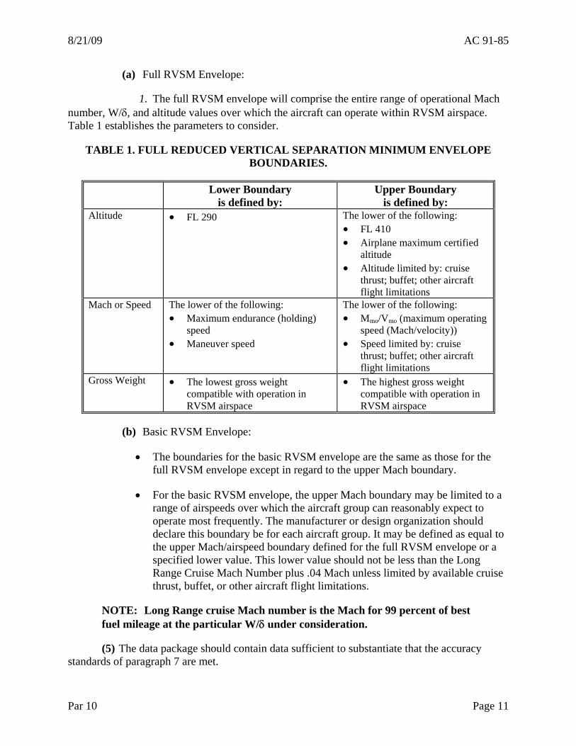
1. The full RVSM envelope will comprise the entire range of operational Mach number, W/δ, and altitude values over which the aircraft can operate within RVSM airspace. Table 1 establishes the parameters to consider.
TABLE 1. FULL REDUCED VERTICAL SEPARATION MINIMUM ENVELOPE BOUNDARIES.
Lower Boundary is defined by:
Upper Boundary is defined by:
Altitude • FL 290 The lower of the following: • FL 410 • Airplane maximum certified
altitude • Altitude limited by: cruise
thrust; buffet; other aircraft flight limitations
Mach or Speed The lower of the following: • Maximum endurance (holding)
speed • Maneuver speed
The lower of the following: • Mmo/Vmo (maximum operating
speed (Mach/velocity)) • Speed limited by: cruise
thrust; buffet; other aircraft flight limitations
Gross Weight • The lowest gross weight compatible with operation in RVSM airspace
• The highest gross weight compatible with operation in RVSM airspace
(b) Basic RVSM Envelope:
• The boundaries for the basic RVSM envelope are the same as those for the full RVSM envelope except in regard to the upper Mach boundary.
• For the basic RVSM envelope, the upper Mach boundary may be limited to a range of airspeeds over which the aircraft group can reasonably expect to operate most frequently. The manufacturer or design organization should declare this boundary be for each aircraft group. It may be defined as equal to the upper Mach/airspeed boundary defined for the full RVSM envelope or a specified lower value. This lower value should not be less than the Long Range Cruise Mach Number plus .04 Mach unless limited by available cruise thrust, buffet, or other aircraft flight limitations.
NOTE: Long Range cruise Mach number is the Mach for 99 percent of best fuel mileage at the particular W/δ under consideration.
(5) The data package should contain data sufficient to substantiate that the accuracy standards of paragraph 7 are met.
Par 10 Page 11
AC 91-85 8/21/09
(a) General.
1. ASE will generally vary with flight condition. The data package should provide coverage of the RVSM envelope sufficient to define the largest errors in the basic and full RVSM envelopes. Note that in the case of group approval the worst flight condition may be different for each of the requirements of paragraphs 8c(3) and 8c(4), and each should be evaluated.
2. Where precision flight calibrations are used to quantify or verify altimetry system performance they may be accomplished by any of the following methods. Flight calibrations should only be performed once appropriate ground checks have been completed. Uncertainties in application of the method must be assessed and taken into account in the data package.
• Precision tracking radar in conjunction with pressure calibration of atmosphere at test altitude.
• Trailing cone.
• Pacer aircraft.
• Any other method acceptable to the FAA or approving authority.
NOTE: When using pacer aircraft it should be understood that the pacer aircraft must have been directly calibrated to a known standard. It is not acceptable to calibrate a pacer aircraft by another pacer aircraft.
(b) In accordance with paragraph 8c, for group approvals and for non-group approvals, a trade may be made between the various error sources that contribute to ASE. (See Appendix 2.) This document does not specify separate limits for the various error sources that contribute to the mean and variable components of ASE as long as the overall ASE accuracy requirements of paragraph 8c are met. For example, in the case of group approval, the smaller the mean of the group and the more stringent the avionics standard, the larger the available allowance for SSE variations. In all cases, present the trade-off adopted in the data package in the form of an error budget that includes all significant error sources. The following sections and the discussion of altimetry system error sources provided in Appendix 2 discuss this in more detail.
(c) Identify avionics equipment by function and equipment part number. The applicant must demonstrate that the avionics equipment can meet the requirements established according to the error budget when operating the equipment in the environmental conditions expected to be met during RVSM operations.
(d) Where approval is sought for an aircraft group, the data package must be sufficient to show that the requirements of paragraph 8c(3) and 8c(4) are met. Because of the statistical nature of these requirements, the content of the data package may vary considerably from group to group.
Page 12 Par 10
8/21/09 AC 91-85
1. Establish the mean and airframe-to-airframe variability of ASE based on precision flight test calibration of a number of aircraft. Where analytical methods are available, it may be possible to enhance the flight test database and to track subsequent change in the mean and variability based on geometric inspections and bench test or any other method acceptable to the approving authority. In the case of derivative aircraft, it may be possible to utilize data from the parent as part of the database. (For example, a fuselage stretch where the only difference in ASEmean between groups could be reliably accounted for by analytical means.)
2. Assess the aircraft-to-aircraft variability of each error source. The error assessment may take various forms as appropriate to the nature and magnitude of the source and the type of data available. For example, for some error sources (especially small ones) it may be acceptable to use specification values to represent 3 SD. For other error sources (especially larger ones) a more comprehensive assessment may be required; this is especially true for airframe error sources where “specification” values of ASE contribution may not have been previously established.
3. In many cases, one or more of the major ASE error sources will be aerodynamic in nature (such as variations in the aircraft surface contour near the static pressure source). If evaluation of these errors is based on geometric measurements, substantiation should be provided that the methodology used is adequate to ensure compliance. (See Appendix 3, Figure 3-2, Compliance Demonstration Ground-To-Flight Test Correlation Process Example.)
4. An error budget should be established to ensure that the standards in paragraphs 8c(3) and 8c(4) are met. As noted in 10b(5)(a)1, the worst flight condition may be different for each of these standards and therefore the component error values may also be different.
5. In showing compliance with the overall requirements, combine the component error sources in an appropriate manner. In most cases, this will involve the algebraic summation of the mean components of the errors, root sum square (RSS) combination of the variable components of the errors, and summation of the RSS value with the absolute value of the overall mean.
NOTE: Be sure that RSS combines only variable component error sources that are independent of each other.
6. The methodology described above for group approval is statistical in nature. This is the result of the statistical nature of the risk analysis and the resulting statistical statements of Appendix 6, paragraphs 5a and 5b. In the context of a statistical method, the statements of Appendix 6, paragraph 5c required reassessment. This item states, “Each individual aircraft in the group shall be built to have ASE contained within ±200 ft.” This statement does not mean that every airframe should be calibrated with a trailing cone or equivalent to demonstrate that ASE is within 200 ft. Such an interpretation would be unduly onerous considering that the risk analysis allows for a small proportion of aircraft to exceed 200 ft. However, if any aircraft is identified as having an error exceeding ±200 ft then it should receive corrective action.
Par 10 Page 13
AC 91-85 8/21/09
(e) Where an aircraft is submitted for approval as a non-group aircraft, the data should be sufficient to show that the requirements of paragraph 8c(8) are met. The data package should specify how the ASE budget has been allocated between residual SSE and avionics error. The operator and the FAA should agree on what data will satisfy approval requirements. The following data should be established:
1. Precision flight test calibration of the aircraft to establish its ASE or SSE over the RVSM envelope should be required. Flight calibration should be performed at points in the flight envelope(s) as agreed by the certifying authority. One of the methods prescribed in paragraph 10b(5)(a)2 should be used.
2. Calibration of the avionics used in the flight test as required to establish residual SSE. The certifying authority should agree to the number of test points. Since the purpose of the flight test is to determine the residual SSE, specially calibrated altimetry equipment may be used.
3. Specifications for the installed altimetry avionics equipment indicating the largest allowable errors will be presented.
4. Using paragraphs 10b(5)(e)1, 10b(5)(e)2, and 10b(5)(e)3, the applicant must demonstrate that the requirements of paragraph 8c(8) are met. If avionics units that are of a different manufacturer or part number are fitted after approval for RVSM operation is granted, the operator should demonstrate to the appropriate FAA office that the standard of avionics equipment provides equivalent altimetry system performance.
(6) The data package must include a definition of the procedures, inspections/tests and limits which will be used to insure that all aircraft approved against the data package “conform to type design,” that is all future approvals, whether of new build or in-service aircraft, meet the error budget allowances developed according to paragraph 10b(5)(b). The tolerances will be established by the data package and include a methodology that allows for tracking the mean and SD for new build aircraft. Define compliance requirements for each potential source of error. (See Appendix 2 for a discussion of error sources, and/or Appendix 3 for examples of compliance procedures.)
(7) Where an operating restriction has been adopted (see paragraph 8c(4)(c)), the package should contain the data and information necessary to document and establish that restriction.
(8) Continued Airworthiness.
(a) Review and update the following items as appropriate to include the effects of RVSM implementation:
1. The Structural Repair Manual with special attention to the areas around the static source, angle of attack sensors and doors if their rigging can affect airflow around the previously mentioned sensors.
2. The Master Minimum Equipment List (MMEL).
Page 14 Par 10
8/21/09 AC 91-85
(b) The data package should include descriptions of any special procedures which are not covered in paragraph 10b(8)(a) but may be needed to insure continued compliance with RVSM requirements as follows:
1. For non-group aircraft where airworthiness approval has been based on flight tests, the continuing integrity and accuracy of the altimetry system shall be demonstrated by periodic ground and flight tests of the aircraft and its altimetry system at periods to be agreed with the approving authority. However, exemption from flight test requirements may be granted if the applicant can adequately demonstrate that the relationship between any subsequent airframe/system degradation and its effects on altimetry system accuracy is understood and adequately compensated/corrected for.
2. To the extent possible, define in-flight defect reporting procedures to facilitate identification of altimetry system error sources. Such procedures could cover acceptable differences between primary and alternate static sources, and others as appropriate.
3. For groups of aircraft where approval is based on geometric inspection, there may be a need for periodic re-inspection, and the interval required should be specified.
c. Data Package Approval. All necessary data should be submitted to the appropriate ACO for action.
d. RVSM Airworthiness Approval. The operator should use the approved data package to demonstrate that the aircraft is in compliance with RVSM performance standards.
e. Post-Approval Modification. Any variation/modification from the initial installation that affects RVSM approval should be approved by the airframe manufacturer or approved design organization and allowed by the FAA to show that RVSM compliance has not been compromised.
11. CONTINUED AIRWORTHINESS (MAINTENANCE REQUIREMENTS).
a. General.
(1) Verify the integrity of the design features necessary to ensure that altimetry systems continue to meet RVSM standards through scheduled tests and/or inspections in conjunction with an approved maintenance program. The operator should review its maintenance procedures and address all aspects of continuing airworthiness affected by RVSM requirements.
(2) Each person or operator should demonstrate that the maintenance facility is adequate to ensure continued compliance with the RVSM maintenance requirements.
b. Maintenance Program Approval Requirements. Each operator requesting RVSM operational approval should submit a maintenance and inspection program that includes any maintenance requirements defined in the approved data package (see paragraph 10) as part of a Continuous Airworthiness Maintenance Program (CAMP) approval or different program approved by the FAA. Although air carriers operating aircraft subject to a CAMP do not have to comply with the provisions of § 91.411, pertaining to altimeter system and altitude reporting
Par 10 Page 15
AC 91-85 8/21/09
Page 16 Par 10
equipment test and inspections, an effective maintenance and inspection program will typically incorporate these provisions as a requirement for maintenance program approval.
c. Maintenance Document Review Requirements. Review the following items as appropriate for RVSM maintenance approval:
• Maintenance manuals.
• Structural repair manuals.
• Standards practices manuals.
• Illustrated parts catalogs.
• Maintenance schedule.
• MMEL/minimum equipment list (MEL).
d. Maintenance Practices. If the operator’s aircraft are subject to an approved maintenance program, that program should contain the maintenance practices outlined in the applicable aircraft and component manufacturer’s maintenance manuals for each aircraft type. Review the following items for compliance for RVSM approval. If the operator’s aircraft is not subject to an approved maintenance program, the following items should be followed:
(1) Maintain all RVSM equipment in accordance with the component manufacturer’s maintenance requirements and the performance requirements outlined in the approved data package.
(2) Any modification, repair, or design change that in any way alters the initial RVSM approval should be subject to a design review by persons approved by the approving authority.
(3) Refer any maintenance practices that may affect the continuing RVSM approval integrity (e.g., the alignment of pitot/static probes, dents, or deformation around static plates) to the approving authority or persons delegated by the authority.
(4) Built-in Test Equipment (BITE) testing is not an acceptable basis for system calibrations, (unless it is shown to be acceptable by the airframe manufacturer with the approval authority’s agreement) and should only be used for fault isolation and troubleshooting purposes.
(5) Some aircraft manufacturers have determined that the removal and replacement of components utilizing quick disconnects and associated fittings, when properly connected, will not require a leak check. While this approach may allow the aircraft to meet static system certification standards when properly connected, it does not always ensure the integrity of the fittings and connectors, nor does it confirm system integrity during component replacement and reconnections. Therefore, a system leak check or visual inspection should be accomplished any time a quick disconnect static line is broken.
8/21/09 AC 91-85
NOTE: If both quick disconnects are broken for any reason, a leak-check must be done.
(6) Maintain airframe and static systems in accordance with the airframe manufacturer’s inspection standards and procedures.
(7) If necessary, to ensure the proper maintenance of airframe geometry for proper surface contours and the mitigation of altimetry system error, surface measurements or skin waviness checks should be made to ensure adherence to the airframe manufacturer’s RVSM tolerances. Perform these tests and inspections as established by the airframe manufacturer. Perform these checks following repairs, or alterations that affect RVSM by having an effect on airframe surface and airflow.
(8) The maintenance and inspection program for the autopilot should ensure continued accuracy and integrity of the automatic altitude control system to meet the height-keeping standards for RVSM operations. This requirement will typically be satisfied with equipment inspections to ensure the equipment is serviceable.
(9) Where the applicant demonstrates the performance of existing equipment is satisfactory for RVSM approval, the FAA should verify that the existing maintenance practices are also consistent with continued RVSM approval integrity. Examples include:
• Altitude alert.
• Automatic altitude control system.
• Air traffic control (ATC) altitude reporting equipment (§ 91.215, ATC transponder and altitude reporting equipment and use).
• Altimetry systems.
e. Maintenance Practices for Noncompliant Aircraft. Those aircraft positively identified as exhibiting height-keeping performance errors which require investigation as specified in paragraph 12i(1) should not be operated under an RVSM approval in airspace where RVSM is applied until the following actions have been taken:
(1) The failure or malfunction is confirmed and isolated by maintenance action and,
(2) Corrective action is carried out in accordance with paragraph 10b(5)(d)6 and verified to ensure RVSM approval integrity.
f. Maintenance Training Requirements. The RVSM approval process should include a review of the operator’s maintenance training program as it relates to the equipment required for RVSM operations. Emphasize the following curriculum segments for initial and recurrent training of shop and line personnel:
(1) Aircraft geometric inspection techniques.
Par 11 Page 17
AC 91-85 8/21/09
Page 18 Par 10
(2) Test equipment calibration/usage techniques.
(3) Any special documentation or procedures introduced by RVSM approval.
g. Test Equipment.
(1) The test equipment should have the capability to demonstrate continuing compliance with the parameters established for RVSM approval in the initial data package or as approved by the approving authority.
(2) Test equipment should be calibrated using approved reference standards traceable to the national standard. Calibrate at periodic intervals as agreed by the approving authority. The approved maintenance program should incorporate effective quality control measures including:
(a) Definition of required test equipment accuracy.
(b) Regular calibrations of test equipment traceable to the approved standard.
NOTE: Determination of calibration interval should be a function of the stability of the test equipment. Establish the calibration interval based on historical data so that degradation is small in relation to the required accuracy.
(c) Procedures to ensure conduct of regular audits of calibration facilities both in-house and outside.
(d) Adherence to acceptable shop and line maintenance practices.
(e) Procedures for controlling operator errors and unusual environmental conditions that may affect calibration accuracy.
12. OPERATIONAL AUTHORIZATION.
a. Purpose and Organization. Paragraph 6 generally describes the administrative process that an operator should follow to receive authorization to operate an aircraft in RVSM airspace. Paragraph 12 provides detailed guidance on the content of operational programs, practices, and procedures. It also describes the steps in the operational authorization process: application for authority, FAA evaluation of this application, and granting of authorization to operate. Appendices 4 and 5 supplement the information contained in this paragraph and include essential information for operational programs.
b. General. The FAA should ensure that each operator can maintain high levels of height-keeping performance. The FAA should be satisfied that operational programs are adequate. Flightcrew training/pilot knowledge as well as operations manuals should be evaluated. Because an RVSM approval requires a high degree of technical analysis, any deviations or equipment substitutions to the FAA-approved RVSM data package (Original Equipment Manufacturer (OEM) Service Bulletin (SB), STC, etc.) must be evaluated by the ACO that granted the original design approval.
8/21/09 AC 91-85
NOTE: The FAA RVSM Documentation Web site http://www.faa.gov/about/office_org/headquarters_offices/ato/service_units/enroute/rvsm/ contains current guidance and information on the aircraft and operator authorization process and links to information on RVSM programs in various areas of the world.
(1) Approval should be granted for each individual aircraft group and each individual aircraft to be used by the operator in RVSM operations. Each aircraft should receive airworthiness approval in accordance with paragraph 10. (See paragraph 10b(2) for the definition of aircraft group.)
(2) Aircraft approved for RVSM can be used in RVSM operations worldwide. This includes RVSM operation in continental areas such as Europe and the United States. Aircraft equipage and altitude-keeping performance requirements were developed using the highest density traffic counts in the world so that aircraft could receive one-time approval for worldwide operations.
(3) Operators that are starting RVSM operations in an RVSM area of operations that is new to them should ensure that their RVSM programs incorporate any operations or continued airworthiness requirements unique to the new area of operations. (See paragraph 12g for information on the form of RVSM authority for new areas of operations.)
c. Pre-application Meeting. A pre-application meeting should be scheduled between the operator and the CHDO/CMO or FSDO. This meeting will inform the operator of FAA expectations regarding approval to operate in an RVSM environment. The content of the operator RVSM application, FAA review and evaluation of the application, validation flight requirements, and conditions for removal of RVSM authority should be basic items of discussion.
d. Content of Operator RVSM Application. The following paragraphs describe the material that an operator applying for RVSM authority should provide to the FAA for review and evaluation at least 60 days prior to the proposed commencement of RVSM operations. Parts 91K, 121, 125, and 135 operators applying for authority to conduct operations in an RVSM area of operations that is new to the operator may modify the application content to address those items unique to the new area of operations. Part 91 operators and part 125 operators holding a letter of deviation authority (LODA), authorizing deviation from part 119, § 119.23 and part 125, § 125.5, that have obtained an LOA for RVSM operations are not required to obtain a separate LOA for individual areas of operation where RVSM is applied. (See paragraph 12g.)
(1) Sufficient documentation should be available to demonstrate that the aircraft complies with RVSM standards.
(a) Documents that contain the inspections and/or modifications that are required to make an in-service aircraft RVSM compliant can take the form of approved SBs, aircraft service changes, STCs or any other format the FAA finds acceptable. Maintenance records document completion of required inspections and/or modifications.
Par 12 Page 19
AC 91-85 8/21/09
Page 20 Par 12
(b) For in-production or new production aircraft, statements of eligibility to conduct RVSM operations can be included in the Aircraft Flight Manual (AFM). Also, Type Certificate Data Sheets (TCDS) can be used to show RVSM eligibility by describing RVSM related avionics configurations and continued airworthiness criteria or providing reference to FAA-approved documentation in the form of a report. Eligibility can be shown in any other format found acceptable to the FAA.
(2) The applicant should provide a configuration list which details all components and equipment relevant to RVSM operations. (See paragraph 8 for a discussion of equipment for RVSM operations.)
(3) Practices and procedures in the following areas should be standardized using the guidelines in Appendix 4: flight planning, preflight procedures at the aircraft for each flight, procedures prior to RVSM airspace entry, in-flight procedures, and flightcrew training procedures. Appendix 4, paragraph 7, contains special emphasis items for flightcrew training. Also, pilots and dispatchers (where applicable) should be knowledgeable on contingency and other procedures unique to specific areas of operation. (See Appendix 4 for sources of information on such procedures. Also, Appendix 5 contains guidance on oceanic contingency procedures.)
(a) Part 91K, 121, 125 and 135 operators should submit training syllabi and other appropriate material to the FAA to show that the operating practices and procedures and training items related to RVSM operations are incorporated in initial and, where warranted, recurrent training programs. (Training for dispatchers should be included, where appropriate.)
(b) Part 91 operators and part 125 operators holding a LODA should show the FAA that pilot knowledge of RVSM operating practices and procedures will be adequate to warrant granting of authorization to conduct RVSM operations. The following are acceptable means for the operator to show the FAA that its pilots will have adequate knowledge of the RVSM operating practices and procedures: 14 CFR part 142 training center certificates without further evaluation; certificates documenting completion of a course of instruction on RVSM policy and procedures; and/or an operator’s in-house training program. The FAA, at its discretion, may evaluate a training course prior to accepting a training certificate.
(4) Submit operations manuals and checklists for FAA review as part of the application process. Generally, the FAA accepts operations manuals. The FAA generally approves only those documents that are required by regulation to be approved. Revise the appropriate manuals and checklists to include information/guidance on standard operating procedures detailed in Appendix 4 and in the appendices that address area of operations unique procedures (e.g., Appendix 5). Appropriate manuals should include a statement of the airspeeds, altitudes, and weights considered in RVSM aircraft approval to include identification of any operations restrictions established for that aircraft group. (See paragraph 8c(4)(c).)
(5) An operating history should be included in the application, if applicable. The applicant should show any events or incidents related to poor height-keeping performance that may indicate weaknesses in training, procedures, maintenance, or the aircraft group intended to be used.
8/21/09 AC 91-85
(6) The following applies to operators that conduct operations under an MEL. An MEL, adopted from the MMEL, should include items pertinent to operating in RVSM airspace.
(7) The operator should submit a maintenance program for approval in accordance with paragraph 10 at the time the operator applies for operational authorization.
(8) The operator should provide a plan for participation in the RVSM monitoring program. This program should normally entail a check of at least a portion of the operator’s aircraft by an independent height-monitoring system. The FAA RVSM Documentation Web site at http://www.faa.gov/about/office_org/headquarters_offices/ato/service_units/enroute/rvsm/ contains guidance on monitoring programs for specific areas of operation. (See paragraph 11h for further discussion of RVSM monitoring programs.)
e. FAA Review and Evaluation of Applications.
(1) Once the application is submitted, the FAA will begin the process of review and evaluation. If the content of the application is insufficient, the FAA will request additional information from the operator.
(2) When all the airworthiness and operational requirements of the application are met, the authority will proceed with the authorization process.
f. Validation Flight(s) for Parts 91, 91K, 121, 125, and 135 Operators. In some cases, review of the RVSM application and programs may suffice for validation purposes. However, the final step of the authorization process may include the completion of a validation flight. For example, an operator new to RVSM flight is more likely to need a validation flight than an operator who has RVSM authority and is simply adding a new aircraft to its operation. The FAA may accompany the operator on a flight through airspace where RVSM is applied to verify that operations and maintenance procedures and practices are applied effectively. If the performance is adequate, operational authorization for RVSM airspace should be granted. If performance is not adequate, then authorization should be delayed. (See FAA Order 8900.1, volume 3, chapter 29.)
g. Form of Authorizing Documents.
(1) Authorization for parts 121, 125, 129, and 135 operators to operate in RVSM airspace should be granted through the issuance of an OpSpec paragraph from Part B (En Route Authorizations, Limitations, and Procedures) and Part D (Aircraft Maintenance). Each aircraft type group for which the operator is granted authority should be listed in OpSpecs. Authorization to conduct RVSM operations in an RVSM area of operations that is new to the operator should be granted by adding the part B RVSM OpSpecs paragraph number to the appropriate area of operations in the Part B paragraph: Authorized Areas of En Route Operation Limitations and Procedures.
(2) Part 91K operators’ authorization to operate in RVSM airspace should be granted through the issuance of a management specifications (MSpecs) paragraph from Part B and Part D. Each aircraft type group for which the operator is granted authority should be listed in MSpecs. Authorization to conduct RVSM operations in an RVSM area of operations that is new
Par 12 Page 21
AC 91-85 8/21/09
Page 22 Par 12
to the operator should be granted by adding the Part B RVSM MSpecs paragraph number to the appropriate area of operations in the Part B paragraph.
(3) Part 91 operators and part 125 operators holding a LODA should be issued an initial letter of authorization (LOA) when the initial authorization process has been completed. Part 91 operators are not required to obtain a new or amended LOA to operate in individual areas of operation where RVSM is implemented. For example, an operator that has obtained an LOA and is conducting RVSM operations in the North Atlantic is not required to obtain another LOA to conduct RVSM operations in the domestic United States.
(4) Operators issued OpSpecs are not required to also obtain an LOA for those operations when they are conducted under part 91, provided that:
(a) The aircraft is operated under the operator name listed on the OpSpecs.
(b) The flight is conducted in an area of operations listed in the OpSpecs.
(c) The aircraft is operated under the conditions under which the OpSpecs were granted (e.g., if the operator holds part 135 OpSpecs, then the pilots used for the part 91 operation must have received part 135 training. If this is not the case, then an LOA would be required).
h. RVSM Monitoring Programs. A program to monitor or verify aircraft height-keeping performance is considered a necessary element of RVSM. RVSM monitoring programs have the primary objective of observing and evaluating aircraft height-keeping performance to gain confidence that airspace users are applying the airplane/operator authorization process in an effective manner and that an equivalent level of safety will be maintained.
NOTE: A height-monitoring system based on global positioning satellites or an Earth-based system may fulfill this function. See “Monitoring Requirements and Procedures” on the RVSM Documentation Web page.
i. Conditions for Removal of RVSM Authority.
(1) The incidence of height-keeping errors that can be tolerated in an RVSM environment is very small. It is incumbent upon each operator to take immediate action to rectify the conditions that caused the error. The operator should also report the event to the FAA within 72 hours with initial analysis of causal factors and measures to prevent further events. The FAA should determine the requirement for follow up reports. Errors which should be reported and investigated are: TVE equal to or greater than ±300 ft (±90 m), ASE equal to or greater than ±245 ft (±75 m), and AAD equal to or greater than ±300 ft (±90 m).
(2) Height-keeping errors fall into two broad categories: 1) errors caused by malfunction of aircraft equipment, and 2) operational errors. An operator who consistently commits errors of either variety may be required to forfeit authority for RVSM operations. If a problem is identified that is related to one specific aircraft type, then RVSM authority may be removed for the operator for that specific type.
8/21/09 AC 91-85
(3) The operator should make an effective, timely response to each height-keeping error. The FAA may consider removing RVSM operational authorization if the operator response to a height-keeping error is not effective or timely. The FAA should also consider the operator’s past performance record in determining the action to take. If an operator shows a history of operational and/or airworthiness errors, then authorization may be removed until the root causes of these errors are shown to be eliminated and RVSM programs and procedures are shown to be effective. The FAA will review each situation on a case-by-case basis.
ORIGINAL SIGNED by John W. McGraw for John M. Allen Director, Flight Standards Service.
Par 12 Page 23 (and 24)

8/21/09 AC 91-85 Appendix 1
Page 1 (and 2)
APPENDIX 1. EXPLANATION OF W/δ
1. Paragraph 10(b)(4) describes the range of flight conditions over which conformity to the altimetry system error (ASE) rules must be shown. The description includes reference to the parameter W/δ. The following discussion is provided for the benefit of readers who may not be familiar with the use of this parameter.
2. It would be difficult to show all of the gross weight, altitude, and speed conditions that constitute the Reduced Vertical Separation Minimum (RVSM) envelope(s) on a single plot. This is because most of the speed boundaries of the envelopes are a function of both altitude and gross weight. As a result, a separate chart of altitude vs. Mach would be required for each aircraft gross weight. Aircraft performance engineers commonly use the following technique to solve this problem.
3. For most jet transports, the required flight envelope can be collapsed to a single chart, with good approximation, by use of the parameter W/δ (weight divided by atmospheric pressure ratio). This fact is due to the relationship between W/δ and the fundamental aerodynamic variables M and lift coefficient as shown below.
AreaWingferenceReSumberach
tCoefficienLiftCRatio Pressure cAtmospheriover Weight W
Hg inches 29.92126 of pressure standard level seaby divided
altitudeflight at pressureambient whereSMC1481
REF
L
REFL
= Ν Μ = Μ
= =
==
δ
δδ
W 2
4. As a result, the flight envelope may be collapsed into one chart by simply plotting W/δ, rather than altitude, versus Mach Number. Since δ is a fixed value for a given altitude, weight can be obtained for a given condition by simply multiplying the W/δ value by δ.
5. Over the RVSM altitude range, it is a good approximation to assume that position error is uniquely related to Mach Number and W/δ for a given aircraft.

8/21/09 AC 91-85 Appendix 2
APPENDIX 2. ALTIMETRY SYSTEM ERROR COMPONENTS
1. INTRODUCTION. Paragraph 10b(5)(b) states that an error budget must be established and presented in the approval data package. The requirements for this error budget are discussed in some detail in paragraph 10b(5)(c) through 10b(5)(e) for group and non-group aircraft. This appendix provides guidance to help ensure that all of the potential error sources are identified and included in the error budget for each particular model.
2. OBJECTIVE OF ASE BUDGET.
a. Purpose. The altimetry system error (ASE) budget demonstrates that the allocation of tolerances among the various parts of the altimetry system is, for the particular data package, consistent with the overall statistical ASE requirements. These individual tolerances within the ASE budget also form the basis of the procedures, defined in the airworthiness approval data package, which will be used to demonstrate that aircraft satisfy the Reduced Vertical Separation Minimum (RVSM) requirements.
b. Components. It is necessary to ensure that the budget takes account of all contributory components of ASE.
c. Group Approval. For group approval it is necessary to ensure either that the budget assesses the combined effect of the component errors in a way that is statistically realistic, or that the worst-case specification values are used.
3. ALTIMETRY SYSTEM ERROR.
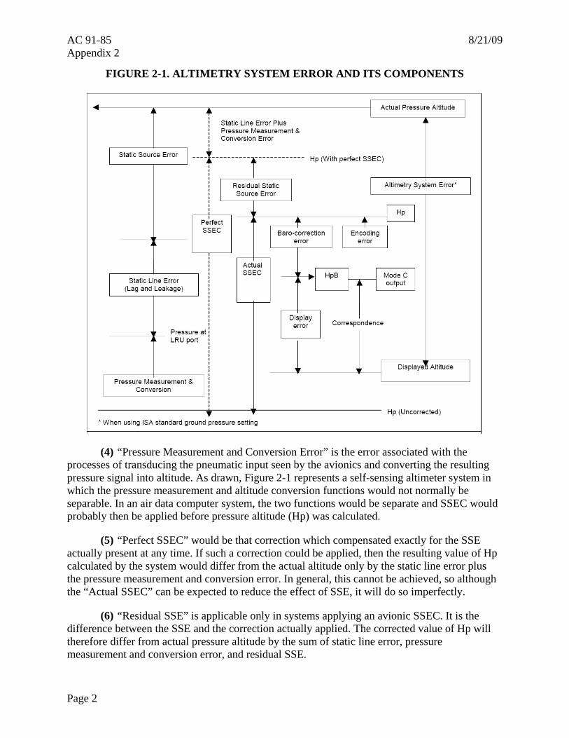
a. Breakdown. Figure 2-1, Altimetry System Error and its Components, shows the breakdown of total ASE into its main components, with each error block representing the error associated with one of the functions needed to generate a display of pressure altitude. This breakdown encompasses all altimetry system errors that can occur, although different system architectures may combine the components in slightly different ways.
(1) The “Actual Altitude” is the pressure altitude corresponding to the undisturbed ambient pressure.
(2) “SSE” (SSE) is the difference between the undisturbed ambient pressure and the pressure within the static port at the input end of the static pressure line.
(3) “Static Line Error” is any difference in pressure along the length of the line.
Page 1
AC 91-85 8/21/09 Appendix 2
FIGURE 2-1. ALTIMETRY SYSTEM ERROR AND ITS COMPONENTS
(4) “Pressure Measurement and Conversion Error” is the error associated with the processes of transducing the pneumatic input seen by the avionics and converting the resulting pressure signal into altitude. As drawn, Figure 2-1 represents a self-sensing altimeter system in which the pressure measurement and altitude conversion functions would not normally be separable. In an air data computer system, the two functions would be separate and SSEC would probably then be applied before pressure altitude (Hp) was calculated.
(5) “Perfect SSEC” would be that correction which compensated exactly for the SSE actually present at any time. If such a correction could be applied, then the resulting value of Hp calculated by the system would differ from the actual altitude only by the static line error plus the pressure measurement and conversion error. In general, this cannot be achieved, so although the “Actual SSEC” can be expected to reduce the effect of SSE, it will do so imperfectly.
(6) “Residual SSE” is applicable only in systems applying an avionic SSEC. It is the difference between the SSE and the correction actually applied. The corrected value of Hp will therefore differ from actual pressure altitude by the sum of static line error, pressure measurement and conversion error, and residual SSE.
Page 2
8/21/09 AC 91-85 Appendix 2
(7) Between Hp and displayed altitude occur the baro-correction error and the display error. Figure 2-1 represents their sequence for a self-sensing altimeter system. Air data computer systems can implement baro-correction in a number of ways that would modify slightly this part of the block diagram, but the errors would still be associated with either the baro-correction function or the display function. The only exception is that those systems that can be switched to operate the display directly from the Hp signal can eliminate baro-correction error where standard ground pressure setting is used, as in RVSM operations.
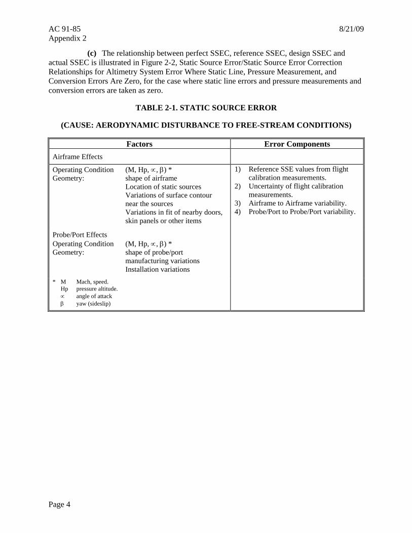
b. Components. The altimetry system errors presented in Table 2-1 and described in paragraph 3a are discussed below in greater detail.
(1) The component parts of SSE are presented in Table 2-1, with the factors that control their magnitude.
(a) The reference SSE is the best estimate of actual SSE, for a single aircraft or an aircraft group, obtained from flight calibration measurements. It is variable with operating condition, characteristically reducing to a family of W/δ curves that are functions of Mach. It includes the effect of any aerodynamic compensation that incorporated in the design once it has been determined, the reference SSE is fixed for the single aircraft or group, although it may be revised in the light of subsequent data.
(b) The test techniques used to derive the reference SSE will have some measurement uncertainty associated with them, even though known instrumentation errors will normally be eliminated from the data. For trailing-cone measurements, the uncertainty arises from limitations on pressure measurement accuracy, calibration of the trailing-cone installation, and variability in installations where more than one is used. Once the reference SSE has been determined, the actual measurement error is fixed, but as it is unknown, it can only be handled within the ASE budget as an estimated uncertainty.
(c) The airframe variability and probe/port variability components arise from differences between the individual airframe and probe/port, and the example(s) of airframe and probe port used to derive the reference SSE.
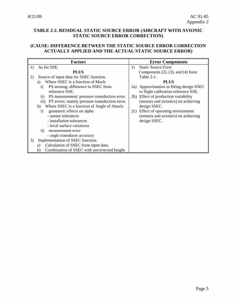
(2) Residual SSE.
(a) Table 2-2 presents the components and factors. Residual SSE consists of those error components that make actual SSE different from the reference value, components 2, 3, and 4 from Table 2-1, plus the amount by which the actual SSEC differs from the value that would correct the reference value exactly, components 2(a), (b) and (c) from Table 2-2.
(b) There will generally be a difference between the SSEC that would exactly compensate the reference SSE, and the SSEC that the avionics is designed to apply. This arises from practical avionics design limitations. The resulting error component 2(a) will therefore be fixed, for a particular flight condition, for the single aircraft or group. Additional variable errors 2(b) and 2(c) arise from those factors that cause a particular set of avionics to apply an actual SSEC that differs from its design value.
Page 3
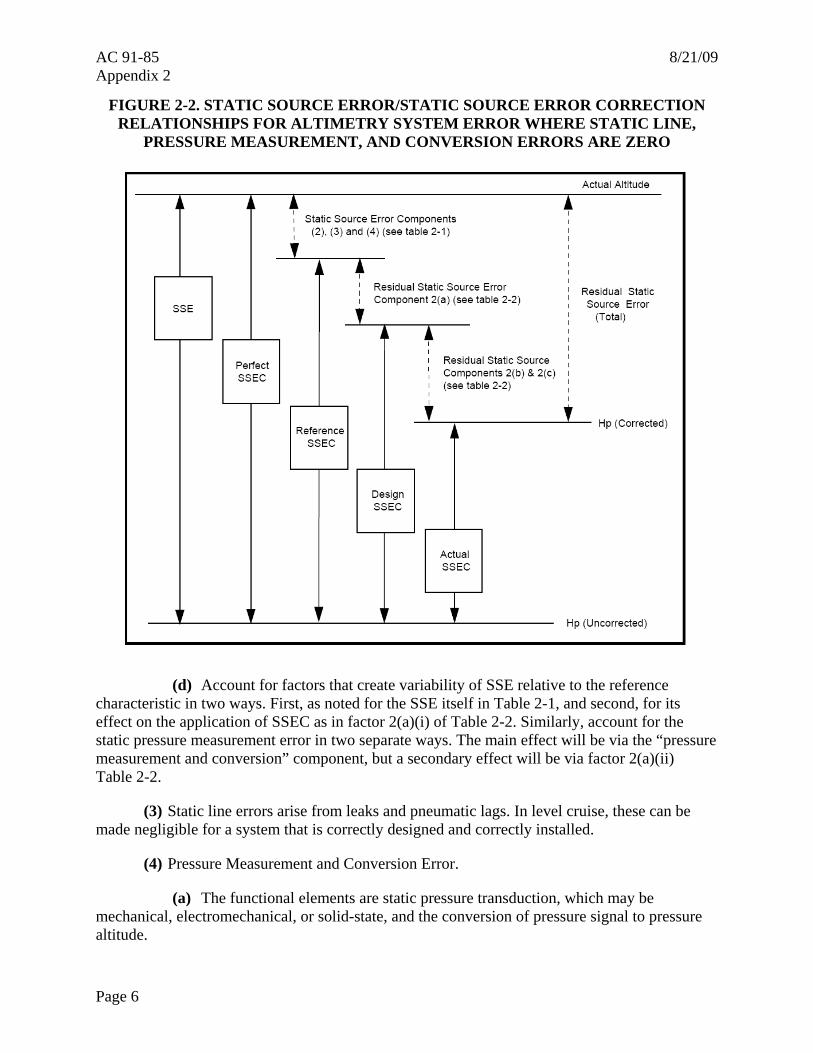
AC 91-85 8/21/09 Appendix 2
(c) The relationship between perfect SSEC, reference SSEC, design SSEC and actual SSEC is illustrated in Figure 2-2, Static Source Error/Static Source Error Correction Relationships for Altimetry System Error Where Static Line, Pressure Measurement, and Conversion Errors Are Zero, for the case where static line errors and pressure measurements and conversion errors are taken as zero.
TABLE 2-1. STATIC SOURCE ERROR
(CAUSE: AERODYNAMIC DISTURBANCE TO FREE-STREAM CONDITIONS)
Factors Error Components Airframe Effects
Operating Condition (M, Hp, ∝, β) * Geometry: shape of airframe
Location of static sources Variations of surface contour near the sources Variations in fit of nearby doors, skin panels or other items
1) Reference SSE values from flight calibration measurements.
2) Uncertainty of flight calibration measurements.
3) Airframe to Airframe variability. 4) Probe/Port to Probe/Port variability.
Probe/Port Effects Operating Condition (M, Hp, ∝, β) * Geometry: shape of probe/port
manufacturing variations Installation variations
* M Mach, speed. Hp pressure altitude. ∝ angle of attack β yaw (sideslip)
Page 4
8/21/09 AC 91-85 Appendix 2
TABLE 2-2. RESIDUAL STATIC SOURCE ERROR (AIRCRAFT WITH AVIONIC STATIC SOURCE ERROR CORRECTION)
(CAUSE: DIFFERENCE BETWEEN THE STATIC SOURCE ERROR CORRECTION ACTUALLY APPLIED AND THE ACTUAL STATIC SOURCE ERROR)
Factors Error Components 1) As for SSE.
PLUS 2) Source of input data for SSEC function.
a) Where SSEC is a function of Mach: i) PS sensing: difference in SSEC from
reference SSE. ii) PS measurement: pressure transduction error. iii) PT errors: mainly pressure transduction error.
b) Where SSEC is a function of Angle of Attack: i) geometric effects on alpha
- sensor tolerances - installation tolerances - local surface variations
ii) measurement error - angle transducer accuracy
3) Implementation of SSEC function. a) Calculation of SSEC from input data. b) Combination of SSEC with uncorrected height.
1) Static Source Error Components (2), (3), and (4) from Table 2-1.
PLUS 2a) Approximation in fitting design SSEC
to flight calibration reference SSE. 2b) Effect of production variability
(sensors and avionics) on achieving design SSEC.
2c) Effect of operating environment (sensors and avionics) on achieving design SSEC.
Page 5
AC 91-85 8/21/09 Appendix 2
FIGURE 2-2. STATIC SOURCE ERROR/STATIC SOURCE ERROR CORRECTION RELATIONSHIPS FOR ALTIMETRY SYSTEM ERROR WHERE STATIC LINE,
PRESSURE MEASUREMENT, AND CONVERSION ERRORS ARE ZERO
(d) Account for factors that create variability of SSE relative to the reference characteristic in two ways. First, as noted for the SSE itself in Table 2-1, and second, for its effect on the application of SSEC as in factor 2(a)(i) of Table 2-2. Similarly, account for the static pressure measurement error in two separate ways. The main effect will be via the “pressure measurement and conversion” component, but a secondary effect will be via factor 2(a)(ii) Table 2-2.
(3) Static line errors arise from leaks and pneumatic lags. In level cruise, these can be made negligible for a system that is correctly designed and correctly installed.
(4) Pressure Measurement and Conversion Error.
(a) The functional elements are static pressure transduction, which may be mechanical, electromechanical, or solid-state, and the conversion of pressure signal to pressure altitude.
Page 6
8/21/09 AC 91-85 Appendix 2
(b) The error components are:
1. Calibration uncertainty;
2. Nominal design performance;
3. Unit to unit manufacturing variations; and
4. Effect of operating environment.
(c) The equipment specification usually covers the combined effect of the error components. If the value of pressure measurements and conversion error used in the error budget is the worst-case specification value, then it is not necessary to assess the above components separately. However, calibration uncertainty, nominal design performance, and effect of operating environment can all contribute to bias errors within the equipment tolerance. Therefore, if it is desired to take statistical account of the likely spread of errors within the tolerance band, it will be necessary to assess their likely interaction for the particular hardware design under consideration.
(d) It is particularly important to ensure that the specified environmental performance is adequate for the intended application.
(5) Baro-Setting Error is defined as the difference between the value displayed and the value applied within the system. For RVSM operation, the value displayed should always be ISA standard ground pressure, but setting mistakes, although part of TVE, are not components of ASE.
(a) The components of Baro-Setting Error are:
1. Resolution of setting knob/display (“Setability”);
2. Transduction of displayed value; and
3. Application of transduced value.
(b) The applicability of these factors and the way that they combine depends on the particular system architecture.
(c) For systems in which the display is remote from the pressure measurement function there may be elements of the transduction and/or application or transduced value error components that arise from the need to transmit and receive the setting between the two locations.
(6) Imperfect conversion from altitude signal to display causes display error. The components are:
(a) Conversion of display input signal;
(b) Graticule/format accuracy; and
Page 7

AC 91-85 8/21/09 Appendix 2
Page 8
(c) Readability.
(7) In self-sensing altimeters, the first of these would normally be separate from the pressure measurement and conversion error.
8/21/09 AC 91-85 Appendix 3
APPENDIX 3. ESTABLISHING AND MONITORING STATIC SOURCE ERRORS
1. GENERAL. Paragraph 10b discusses the requirements for the data package in general terms. Paragraph 10b(5)(d)3 requires that the methodology used to establish the static source error (SSE) be substantiated. Paragraph 10b(6) further requires that procedures be established to ensure conformity of newly manufactured airplanes. There may be many ways of satisfying these requirements; two examples are included here.
2. EXAMPLE 1.
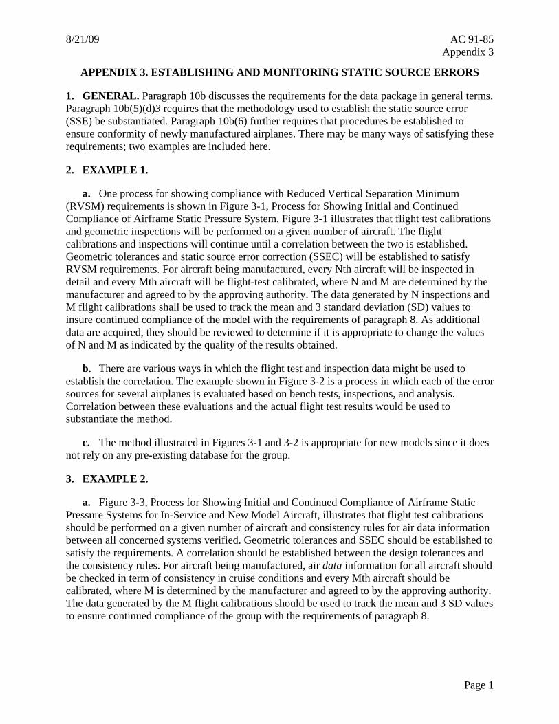
a. One process for showing compliance with Reduced Vertical Separation Minimum (RVSM) requirements is shown in Figure 3-1, Process for Showing Initial and Continued Compliance of Airframe Static Pressure System. Figure 3-1 illustrates that flight test calibrations and geometric inspections will be performed on a given number of aircraft. The flight calibrations and inspections will continue until a correlation between the two is established. Geometric tolerances and static source error correction (SSEC) will be established to satisfy RVSM requirements. For aircraft being manufactured, every Nth aircraft will be inspected in detail and every Mth aircraft will be flight-test calibrated, where N and M are determined by the manufacturer and agreed to by the approving authority. The data generated by N inspections and M flight calibrations shall be used to track the mean and 3 standard deviation (SD) values to insure continued compliance of the model with the requirements of paragraph 8. As additional data are acquired, they should be reviewed to determine if it is appropriate to change the values of N and M as indicated by the quality of the results obtained.
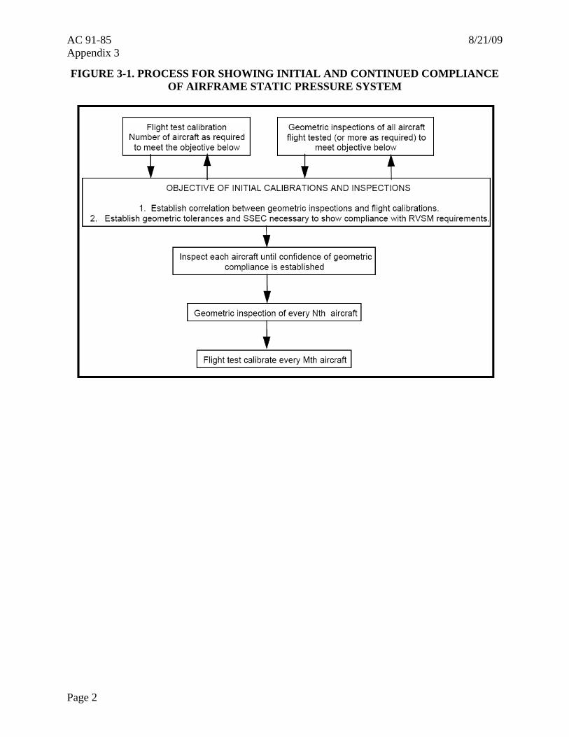
b. There are various ways in which the flight test and inspection data might be used to establish the correlation. The example shown in Figure 3-2 is a process in which each of the error sources for several airplanes is evaluated based on bench tests, inspections, and analysis. Correlation between these evaluations and the actual flight test results would be used to substantiate the method.
c. The method illustrated in Figures 3-1 and 3-2 is appropriate for new models since it does not rely on any pre-existing database for the group.
3. EXAMPLE 2.
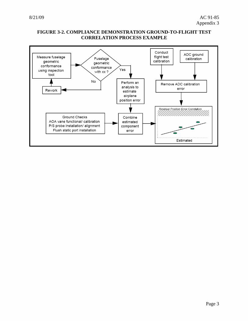
a. Figure 3-3, Process for Showing Initial and Continued Compliance of Airframe Static Pressure Systems for In-Service and New Model Aircraft, illustrates that flight test calibrations should be performed on a given number of aircraft and consistency rules for air data information between all concerned systems verified. Geometric tolerances and SSEC should be established to satisfy the requirements. A correlation should be established between the design tolerances and the consistency rules. For aircraft being manufactured, air data information for all aircraft should be checked in term of consistency in cruise conditions and every Mth aircraft should be calibrated, where M is determined by the manufacturer and agreed to by the approving authority. The data generated by the M flight calibrations should be used to track the mean and 3 SD values to ensure continued compliance of the group with the requirements of paragraph 8.
Page 1
AC 91-85 8/21/09 Appendix 3
FIGURE 3-1. PROCESS FOR SHOWING INITIAL AND CONTINUED COMPLIANCE OF AIRFRAME STATIC PRESSURE SYSTEM
Page 2
8/21/09 AC 91-85 Appendix 3
FIGURE 3-2. COMPLIANCE DEMONSTRATION GROUND-TO-FLIGHT TEST CORRELATION PROCESS EXAMPLE
Page 3
AC 91-85 8/21/09 Appendix 3
Page 4
FIGURE 3-3. PROCESS FOR SHOWING INITIAL AND CONTINUED COMPLIANCE OF AIRFRAME STATIC PRESSURE SYSTEMS FOR IN-SERVICE AND NEW
MODEL AIRCRAFT
8/21/09 AC 91-85 Appendix 4
APPENDIX 4. TRAINING PROGRAMS AND OPERATING PRACTICES AND PROCEDURES
1. INTRODUCTION. The following items (detailed in paragraphs 2 through 7) should be standardized and incorporated into training programs and operating practices and procedures. Certain items may already be adequately standardized in existing operator programs and procedures. New technologies may also eliminate the need for certain crew actions. If this is the case, then the intent of this guidance can be considered to be met.
NOTE: This advisory circular (AC) was written for use by a wide variety of operator types (e.g., 14 CFR part 91, 91K, 121, 125, 129, 135 operators) and therefore, certain items are included for purposes of clarity and completeness.
2. FLIGHT PLANNING. During flight planning, the flightcrew and dispatchers, if applicable, should pay particular attention to conditions which may affect operation in Reduced Vertical Separation Minimum (RVSM) airspace. These include, but may not be limited to:
a. Verifying that the aircraft is approved for RVSM operations.
b. Annotating the flight plan to be filed with the Air Traffic Service Provider to show that the aircraft and operator are authorized for RVSM operations. Block 3 of the FAA Flight Plan (Aircraft Type/Special Equipment) should be annotated with the appropriate letter from the current Aeronautical Information Manual (AIM) for filing in RVSM airspace. Block 10 (equipment) of the International Civil Aviation Organization (ICAO) flight plan should be annotated with the letter W for filing in RVSM airspace.
c. Reported and forecast weather conditions on the route of flight;
d. Minimum equipment requirements pertaining to height-keeping systems; and
e. If required for the specific aircraft group; accounting for any aircraft operating restrictions related to RVSM airworthiness approval. (See paragraph 8c(4)(c).)
3. PREFLIGHT PROCEDURES. Accomplish the following actions during preflight:
a. Review maintenance logs and forms to ascertain the condition of equipment required for flight in the RVSM airspace. Ensure that maintenance action has been taken to correct defects to required equipment;
b. During the external inspection of aircraft, pay particular attention to the condition of static sources and the condition of the fuselage skin near each static source and any other component that affects altimetry system accuracy. (A qualified and authorized person other than the pilot, e.g., a Flight Engineer (FE) or maintenance personnel may perform this check.)
c. Before takeoff, the aircraft altimeters should be set to the local altimeter atmospheric pressure at nautical height (QNH) setting and should display a known elevation (e.g., field elevation) within the limits specified in aircraft operating manuals. The difference between the
Page 1
AC 91-85 8/21/09 Appendix 4
known elevation and the elevation displayed on the altimeters should not exceed 75 ft. The two primary altimeters should also agree within limits specified by the aircraft operating manual. An alternative procedure using atmospheric pressure at field elevation (QFE) may also be used;
d. Before takeoff, equipment required for flight in RVSM airspace should be operational, and indications of malfunction should be resolved.
4. PROCEDURES BEFORE RVSM AIRSPACE ENTRY. If any of the required equipment fails prior to the aircraft entering RVSM airspace, the pilot should request a new clearance so as to avoid flight in this airspace. The following equipment should be operating normally at entry into RVSM airspace:
a. Two primary altitude measurement systems.
b. One automatic altitude-control system.
c. One altitude-alerting device.
NOTE: The operator should ascertain the requirement for an operational transponder in each RVSM area where operations are intended.
5. IN-FLIGHT PROCEDURES. Incorporate the following policies into flightcrew training and procedures:
a. Flightcrews should comply with aircraft operating restrictions (if required for the specific aircraft group) related to RVSM airworthiness approval. (See paragraph 8c(4)(c).)
b. Place emphasis on promptly setting the sub-scale on all primary and standby altimeters to 29.92 in. Hg/1013.2 (hPa) when passing the transition altitude and rechecking for proper altimeter setting when reaching the initial cleared flight level (CFL);
c. In level cruise, it is essential that the aircraft is flown at the CFL. This requires that particular care is taken to ensure that air traffic control (ATC) clearances are fully understood and followed. Except in contingency or emergency situations, the aircraft should not intentionally depart from CFL without a positive clearance from ATC;
d. During cleared transition between levels, the aircraft should not be allowed to overshoot or undershoot the cleared flight level by more than 150 ft (45 m);
NOTE: It is recommended that the level off be accomplished using the altitude capture feature of the automatic altitude-control system, if installed.
e. An automatic altitude-control system should be operative and engaged during level cruise, except when circumstances such as the need to retrim the aircraft or turbulence require disengagement. In any event, adherence to cruise altitude should be done by reference to one of the two primary altimeters;
f. The altitude-alerting system should be operational;
Page 2
8/21/09 AC 91-85 Appendix 4
g. At intervals of approximately 1 hour, make cross-checks between the primary altimeters and the stand-by altimeter. A minimum of two primary altimeters should agree within 200 ft (60 m) or a lesser value if specified in the aircraft operating manual. (Failure to meet this condition will require that the altimetry system be reported as defective and notified to ATC). Note the difference between the primary and stand-by altimeters for use in contingency situations.
(1) The normal pilot scan of cockpit instruments should suffice for altimeter crosschecking on most flights.
(2) When operating under positive radar control, the initial altimeter cross-check should be performed after level off. On Class II navigation legs, a cross-check should be performed and recorded in the vicinity of the point where Class II navigation is begun (e.g., on coast out). The readings of the primary and standby altimeters should be recorded and available for use in contingency situations. (Class II navigation is defined in FAA Order 8900.1, Volume 4, Chapter 1, Section 4, Class II Navigation.)
(3) Some aircraft have automatic comparators that compare the two primary altimetry systems. The comparators include a monitoring, warning, and fault function. The faults may be recorded automatically by the system but a record of the differences in the primary altimetry systems may not be easily derived.
NOTE: Future systems may make use of automatic altimeter comparators in lieu of cross-checks by the crew.
h. Normally, the altimetry system being used to control the aircraft should be selected to provide the input to the altitude-reporting transponder transmitting information to ATC.
i. If ATC notifies the pilot of an assigned altitude deviation (AAD) error that equals or exceeds 300 ft (90 m) then the pilot should take action to return to cleared flight level (CFL) as quickly as possible.
j. Contingency procedures after entering RVSM airspace. The pilot should notify ATC of contingencies (aircraft system failures, weather conditions) which affect the ability to maintain the CFL and coordinate a plan of action. “Area of Operations Specific Information” on the FAA RVSM Documentation Web site at http://www.faa.gov/about/office_org/headquarters_offices/ato/service_units/enroute/rvsm/ contains contingency procedures for the domestic United States and individual regions of the world. Appendix 5 contains detailed guidance for contingency procedures for oceanic airspace.
Page 3
AC 91-85 8/21/09 Appendix 4
Page 4
6. POST FLIGHT.
a. In making maintenance logbook entries against malfunctions in height-keeping systems, the pilot should provide sufficient detail to enable maintenance to effectively troubleshoot and repair the system. The pilot should detail the actual defect and the crew action taken to try to isolate and rectify the fault. Note the following information when appropriate:
(1) Primary and standby altimeter readings.
(2) Altitude selector setting.
(3) Subscale setting on altimeter.
(4) Autopilot used to control the airplane and any differences when the alternate system was selected.
(5) Differences in altimeter readings if alternate static ports selected.
(6) Use of air data computer selector for fault diagnosis procedure.
(7) Transponder selected to provide altitude information to ATC and any difference if alternate transponder or altitude source is manually selected.
7. SPECIAL EMPHASIS ITEMS: FLIGHTCREW TRAINING. The following items should also be included in flightcrew training programs:
a. Area of Operations Specific Policy and Procedures Including Standard ATC Phraseology. (See “Area of Operations Specific Information” on the FAA RVSM Documentation Web site at http://www.faa.gov/about/office_org/headquarters_offices/ato/service_units/enroute/rvsm/ for RVSM operational policy and procedures for individual areas of operation including the domestic United States).
b. Importance of crewmembers cross checking each other to ensure that ATC clearances are promptly and correctly complied with.
c. Use and limitations in terms of accuracy of standby altimeters in contingencies. Where applicable, the pilot should review the application of static source correction error/position correction error (SSEC/PEC) through the use of correction cards.
d. Problems of visual perception of other aircraft at 1,000 ft (300 m) planned separation during night conditions, when encountering local phenomena such as northern lights, for opposite and same direction traffic, and during turns.
e. Characteristics of aircraft altitude capture systems that may lead to the occurrence of overshoots.
f. Operational procedures and operating characteristics related to Traffic Alert and Collision Avoidance System (TCAS)/Airborne Collision Avoidance System (ACAS) operation in an
8/21/09 AC 91-85 Appendix 4
RVSM operation. See “TCAS Documents” under “Documents Applicable to All RVSM Approvals” on the RVSM Documentation Web site http://www.faa.gov/about/office_org/headquarters_offices/ato/service_units/enroute/rvsm/.
g. Relationship between the altimetry, automatic altitude control, and transponder systems in normal and abnormal situations.
h. Aircraft operating restrictions (if required for the specific aircraft group) related to RVSM airworthiness approval. (See paragraph 8c(4)(c).)
i. For those operators authorized to conduct oceanic operations—use of Strategic Lateral Offset Procedures (SLOP) in oceanic airspace to mitigate the effect of wake turbulence and the effect of operational errors. The FAA RVSM Documentation Web site at http://www.faa.gov/about/office_org/headquarters_offices/ato/service_units/enroute/rvsm/ contains “Special Area of Operations” information containing SLOP procedures.
Page 5 (and 6)

8/21/09 AC 91-85 Appendix 5
APPENDIX 5. SPECIFIC PROCEDURES FOR OCEANIC AIRSPACE
1. INTRODUCTION.
a. Reduced Vertical Separation Minimum (RVSM) was initially implemented in North Atlantic Minimum Navigation Performance Specification (NAT MNPS) airspace in March 1997. The guidance that follows has been applied in the NAT region since that time. It is also applied to RVSM operations in the Pacific, West Atlantic and other oceanic airspace.
b. This appendix contains information on procedures that are unique to oceanic RVSM airspace where direct voice communications between pilots and air traffic control (ATC) is not available.
2. GENERAL INFORMATION: AIRSPACE DIMENSIONS.
a. NAT MNPS Airspace.
(1) When RVSM was implemented in NAT MNPS airspace, NAT MNPS authorization expanded to encompass demonstration of special qualification for both lateral navigation and height-keeping performance.
(2) NAT MNPS airspace now has a ceiling of FL 420 and a floor of FL 285.
b. RVSM in Other Oceanic Airspace. The FAA RVSM Web site at http://www.faa.gov/about/office_org/headquarters_offices/ato/service_units/enroute/rvsm/ provides a chart showing oceanic and continental airspace in the world where RVSM has been implemented.
3. INTENDED USE OF THE MATERIAL IN THIS APPENDIX.
a. Paragraph 4, Basic Concepts for Contingencies. This paragraph provides an overview of contingency procedures. It is intended to orient the pilot’s thinking to the concepts involved and aid in understanding the specific guidance detailed in paragraph 5 and 6. This material should be included in training programs and appropriate flightcrew manuals.
b. Paragraph 5, Guidance to the Pilot in the Event of Equipment Failures or Encounters with Turbulence after Entering RVSM Airspace. This paragraph details summary guidance on specific actions for the pilot to take to mitigate the potential for conflict with other aircraft in the situations listed. It should be reviewed in conjunction with paragraph 6 of this appendix that provides additional technical and operational detail. The pilot actions in paragraph 5 should be considered required pilot knowledge and should be included in training/qualification programs and appropriate flightcrew manuals.
c. Paragraph 6, Expanded Equipment Failure and Turbulence Encounter Scenarios. This paragraph reviews the situations discussed in paragraph 5 in greater detail. The material may be used in training programs as an operator deems appropriate.
Page 1
AC 91-85 8/21/09 Appendix 5
d. Paragraph 7, Special Procedures for In-Flight Contingencies Published for Individual ICAO Regions in Doc. 7030. These procedures should be considered required pilot knowledge. The material may be condensed for ease of presentation and should be included in training/qualification programs and appropriate flightcrew manuals. Contingency Procedures published in International Civil Aviation Organization (ICAO) Doc. 7030, Regional Supplementary Procedures, provides differences for individual regions of the world.
e. Paragraph 8, Wake Turbulence Procedures. Paragraph 8 discusses published procedures for the pilot to follow in the event that wake turbulence is encountered. These procedures should be considered required pilot knowledge.
f. Paragraph 9, Transponder Failure. Paragraph 9 highlights the necessity for pilots to be informed on policy and procedures established for operation in RVSM transition areas. This information should be addressed in training programs and manuals.
4. BASIC CONCEPTS FOR CONTINGENCIES.
a. Specific Guidance. The basic concepts for contingencies described in this paragraph were developed from the specific guidance contained in Chapter 15 of ICAO Doc. 4444, Special In-flight Contingencies. Contingency procedures become complicated when specific situations are detailed. However, if the details are examined in the context of certain basic concepts, then they are more easily understood. Reviewing these concepts should serve to aid pilots’ understanding of the specific contingency procedures detailed in ICAO Doc. 4444 paragraphs. Contingency Procedures published in ICAO Doc. 7030, Regional Supplementary Procedures, provides differences for individual regions of the world.
b. Basic Concepts for Contingencies.
(1) Do not interpret guidance for contingency procedures in any way that prejudices the final authority and responsibility of the pilot in command (PIC) for the safe operation of the aircraft.
(2) If the pilot is unsure of the vertical or lateral position of the aircraft or the aircraft deviates from its assigned altitude or track for cause without prior ATC clearance, then the pilot must take action to mitigate the potential for collision with aircraft on adjacent routes or flight levels.
NOTE: In this situation, the pilot should alert adjacent aircraft by making maximum use of aircraft lighting and broadcasting position, flight level (FL), and intentions on 121.5 megahertz (MHz) (as a back-up, the appropriate very high frequency (VHF) inter-pilot air-to-air frequency may be used).
(3) Unless the nature of the contingency dictates otherwise, the pilot should advise ATC as soon as possible of a contingency situation and if possible, request an ATC clearance before deviating from the assigned route or FL.
(4) If a revised ATC clearance cannot be obtained in a timely manner and action is required to avoid potential conflict with other aircraft, then the aircraft should be flown at an
Page 2
8/21/09 AC 91-85 Appendix 5
(a) Acquire and maintain in either direction a track laterally separated by 28 km (15 NM) from the assigned route; and
(b) Once established on the offset track, climb or descend to select a FL which differs from those normally used by 150 m (500 ft);
(c) The pilot may also consider descending below FL 285 or climbing above FL 410. (The vast majority of oceanic traffic operates between FL 290 and 410. Flight above FL 410 or below FL 285 may limit exposure to conflict with other aircraft.)
(5) When executing a contingency maneuver the pilot should:
(a) Watch for conflicting traffic both visually and by reference to Airborne Collision Avoidance System (ACAS) or Traffic Alert and Collision Avoidance System (TCAS), if equipped.
(b) Continue to alert other aircraft using 121.5 MHz (as a back-up, the VHF inter-pilot air-to-air frequency (VHF 123.45) may be used) and aircraft lights.
(c) Continue to fly offset tracks or altitudes until an ATC clearance is obtained.
(d) Obtain an ATC clearance as soon as possible.
5. GUIDANCE TO THE PILOT IN THE EVENT OF EQUIPMENT FAILURES OR ENCOUNTERS WITH TURBULENCE AFTER ENTRY INTO RVSM AIRSPACE (INCLUDING EXPECTED ATC ACTIONS). In addition to emergency conditions that require immediate descent, such as loss of thrust or pressurization, make ATC aware of the less explicit conditions that may make it impossible for an aircraft to maintain its cleared flight level (CFL) appropriate to RVSM. Controllers should react to such conditions but these actions cannot be specified, as they will be dynamically affected by the real-time situation.
a. Objective of the Guidance Material. The following material is provided with the purpose of giving the pilot guidance on actions to take under certain conditions of equipment failure and encounters with turbulence. It also describes the expected ATC controller actions in these situations. It is recognized that the pilot and controller will use judgment to determine the action most appropriate to any given situation. The guidance material recognizes that for certain equipment failures, the safest course of action may be for the aircraft to maintain the assigned FL and route while the pilot and controller take precautionary action to protect separation. For extreme cases of equipment failure, however, the guidance recognizes that the safest course of action may be for the aircraft to depart from the cleared FL or route by obtaining a revised ATC clearance or if unable to obtain prior ATC clearance, executing the established ICAO Doc. 4444 and Doc. 7030 contingency maneuvers for the area of operation.
Page 3
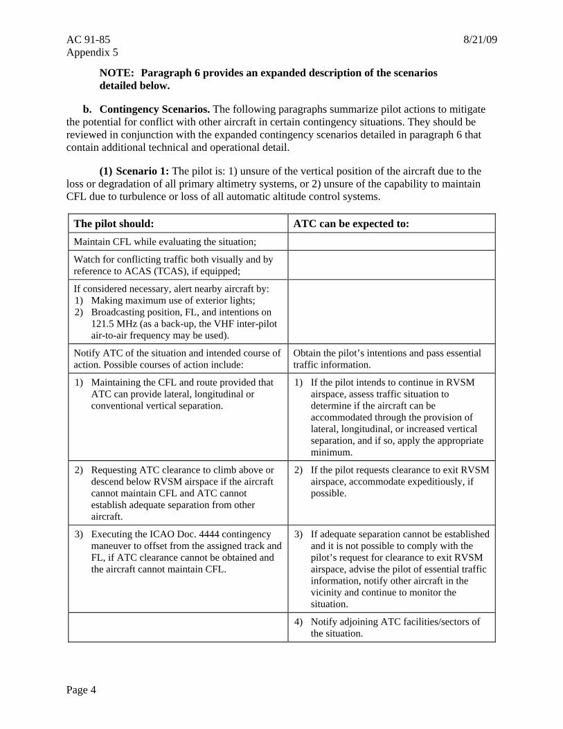
AC 91-85 8/21/09 Appendix 5
NOTE: Paragraph 6 provides an expanded description of the scenarios detailed below.
b. Contingency Scenarios. The following paragraphs summarize pilot actions to mitigate the potential for conflict with other aircraft in certain contingency situations. They should be reviewed in conjunction with the expanded contingency scenarios detailed in paragraph 6 that contain additional technical and operational detail.
(1) Scenario 1: The pilot is: 1) unsure of the vertical position of the aircraft due to the loss or degradation of all primary altimetry systems, or 2) unsure of the capability to maintain CFL due to turbulence or loss of all automatic altitude control systems.
The pilot should: ATC can be expected to: Maintain CFL while evaluating the situation;
Watch for conflicting traffic both visually and by reference to ACAS (TCAS), if equipped;
If considered necessary, alert nearby aircraft by: 1) Making maximum use of exterior lights; 2) Broadcasting position, FL, and intentions on
121.5 MHz (as a back-up, the VHF inter-pilot air-to-air frequency may be used).
Notify ATC of the situation and intended course of action. Possible courses of action include:
Obtain the pilot’s intentions and pass essential traffic information.
1) Maintaining the CFL and route provided that ATC can provide lateral, longitudinal or conventional vertical separation.
1) If the pilot intends to continue in RVSM airspace, assess traffic situation to determine if the aircraft can be accommodated through the provision of lateral, longitudinal, or increased vertical separation, and if so, apply the appropriate minimum.
2) Requesting ATC clearance to climb above or descend below RVSM airspace if the aircraft cannot maintain CFL and ATC cannot establish adequate separation from other aircraft.
2) If the pilot requests clearance to exit RVSM airspace, accommodate expeditiously, if possible.
3) Executing the ICAO Doc. 4444 contingency maneuver to offset from the assigned track and FL, if ATC clearance cannot be obtained and the aircraft cannot maintain CFL.
3) If adequate separation cannot be established and it is not possible to comply with the pilot’s request for clearance to exit RVSM airspace, advise the pilot of essential traffic information, notify other aircraft in the vicinity and continue to monitor the situation.
4) Notify adjoining ATC facilities/sectors of the situation.
Page 4
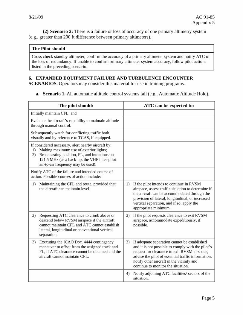
8/21/09 AC 91-85 Appendix 5
(2) Scenario 2: There is a failure or loss of accuracy of one primary altimetry system (e.g., greater than 200 ft difference between primary altimeters).
The Pilot should Cross check standby altimeter, confirm the accuracy of a primary altimeter system and notify ATC of the loss of redundancy. If unable to confirm primary altimeter system accuracy, follow pilot actions listed in the preceding scenario.
6. EXPANDED EQUIPMENT FAILURE AND TURBULENCE ENCOUNTER SCENARIOS. Operators may consider this material for use in training programs.
a. Scenario 1. All automatic altitude control systems fail (e.g., Automatic Altitude Hold).
The pilot should: ATC can be expected to: Initially maintain CFL, and
Evaluate the aircraft’s capability to maintain altitude through manual control.
Subsequently watch for conflicting traffic both visually and by reference to TCAS, if equipped.
If considered necessary, alert nearby aircraft by: 1) Making maximum use of exterior lights; 2) Broadcasting position, FL, and intentions on
121.5 MHz (as a back-up, the VHF inter-pilot air-to-air frequency may be used).
Notify ATC of the failure and intended course of action. Possible courses of action include:
1) Maintaining the CFL and route, provided that the aircraft can maintain level.
1) If the pilot intends to continue in RVSM airspace, assess traffic situation to determine if the aircraft can be accommodated through the provision of lateral, longitudinal, or increased vertical separation, and if so, apply the appropriate minimum.
2) Requesting ATC clearance to climb above or descend below RVSM airspace if the aircraft cannot maintain CFL and ATC cannot establish lateral, longitudinal or conventional vertical separation.
2) If the pilot requests clearance to exit RVSM airspace, accommodate expeditiously, if possible.
3) Executing the ICAO Doc. 4444 contingency maneuver to offset from the assigned track and FL, if ATC clearance cannot be obtained and the aircraft cannot maintain CFL.
3) If adequate separation cannot be established and it is not possible to comply with the pilot’s request for clearance to exit RVSM airspace, advise the pilot of essential traffic information, notify other aircraft in the vicinity and continue to monitor the situation.
4) Notify adjoining ATC facilities/ sectors of the situation.
Page 5
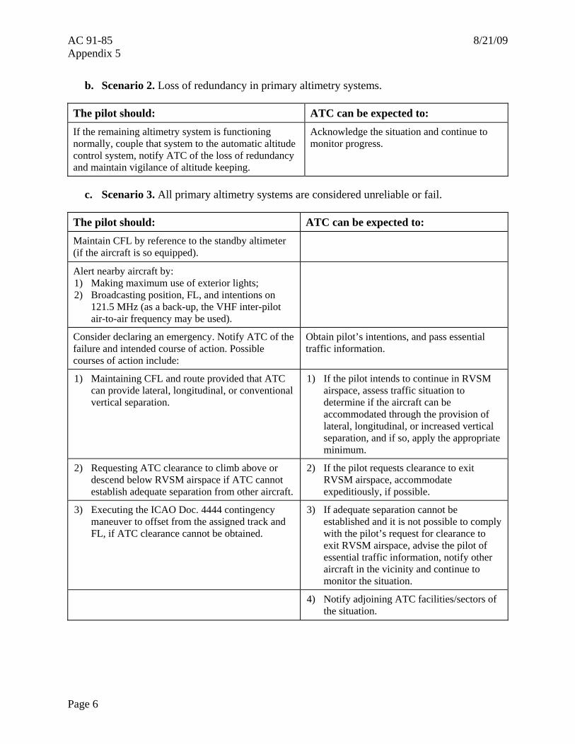
AC 91-85 8/21/09 Appendix 5
b. Scenario 2. Loss of redundancy in primary altimetry systems.
The pilot should: ATC can be expected to: If the remaining altimetry system is functioning normally, couple that system to the automatic altitude control system, notify ATC of the loss of redundancy and maintain vigilance of altitude keeping.
Acknowledge the situation and continue to monitor progress.
c. Scenario 3. All primary altimetry systems are considered unreliable or fail.
The pilot should: ATC can be expected to: Maintain CFL by reference to the standby altimeter (if the aircraft is so equipped).
Alert nearby aircraft by: 1) Making maximum use of exterior lights; 2) Broadcasting position, FL, and intentions on
121.5 MHz (as a back-up, the VHF inter-pilot air-to-air frequency may be used).
Consider declaring an emergency. Notify ATC of the failure and intended course of action. Possible courses of action include:
Obtain pilot’s intentions, and pass essential traffic information.
1) Maintaining CFL and route provided that ATC can provide lateral, longitudinal, or conventional vertical separation.
1) If the pilot intends to continue in RVSM airspace, assess traffic situation to determine if the aircraft can be accommodated through the provision of lateral, longitudinal, or increased vertical separation, and if so, apply the appropriate minimum.
2) Requesting ATC clearance to climb above or descend below RVSM airspace if ATC cannot establish adequate separation from other aircraft.
2) If the pilot requests clearance to exit RVSM airspace, accommodate expeditiously, if possible.
3) Executing the ICAO Doc. 4444 contingency maneuver to offset from the assigned track and FL, if ATC clearance cannot be obtained.
3) If adequate separation cannot be established and it is not possible to comply with the pilot’s request for clearance to exit RVSM airspace, advise the pilot of essential traffic information, notify other aircraft in the vicinity and continue to monitor the situation.
4) Notify adjoining ATC facilities/sectors of the situation.
Page 6
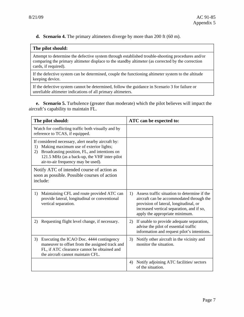
8/21/09 AC 91-85 Appendix 5
d. Scenario 4. The primary altimeters diverge by more than 200 ft (60 m).
The pilot should: Attempt to determine the defective system through established trouble-shooting procedures and/or comparing the primary altimeter displace to the standby altimeter (as corrected by the correction cards, if required).
If the defective system can be determined, couple the functioning altimeter system to the altitude keeping device.
If the defective system cannot be determined, follow the guidance in Scenario 3 for failure or unreliable altimeter indications of all primary altimeters.
e. Scenario 5. Turbulence (greater than moderate) which the pilot believes will impact the aircraft’s capability to maintain FL.
The pilot should: ATC can be expected to: Watch for conflicting traffic both visually and by reference to TCAS, if equipped.
If considered necessary, alert nearby aircraft by: 1) Making maximum use of exterior lights; 2) Broadcasting position, FL, and intentions on
121.5 MHz (as a back-up, the VHF inter-pilot air-to-air frequency may be used).
Notify ATC of intended course of action as soon as possible. Possible courses of action include:
1) Maintaining CFL and route provided ATC can provide lateral, longitudinal or conventional vertical separation.
1) Assess traffic situation to determine if the aircraft can be accommodated through the provision of lateral, longitudinal, or increased vertical separation, and if so, apply the appropriate minimum.
2) Requesting flight level change, if necessary. 2) If unable to provide adequate separation, advise the pilot of essential traffic information and request pilot’s intentions.
3) Executing the ICAO Doc. 4444 contingency maneuver to offset from the assigned track and FL, if ATC clearance cannot be obtained and the aircraft cannot maintain CFL.
3) Notify other aircraft in the vicinity and monitor the situation.
4) Notify adjoining ATC facilities/ sectors of the situation.
Page 7
AC 91-85 8/21/09 Appendix 5
Page 8
7. SPECIAL PROCEDURES FOR IN-FLIGHT CONTINGENCIES PUBLISHED FOR INDIVIDUAL ICAO REGIONS IN DOC. 7030.
a. Basic contingency procedures are in ICAO Doc. 4444, Chapter 15, Procedures Relating to Emergencies, Communications Failures and Contingencies.
b. ICAO Doc. 4444 and Doc. 7030 is the source document for specific contingency procedures applicable to individual ICAO regions. Always consult Doc. 7030 before training material or manuals are developed.
8. WAKE TURBULENCE PROCEDURES. SLOP allows aircraft to offset from the centerline of its track by one NM or two NM to the right for wake turbulence avoidance and for increased safety. The FAA RVSM Documentation Web site at http://www.faa.gov/about/office_org/headquarters_offices/ato/service_units/enroute/rvsm/ contains the full SLOP procedure.
9. TRANSPONDER FAILURE. The provider States will determine the specific actions that ATC will take in the event of transponder failure in RVSM.
8/21/09 AC 91-85 Appendix 6
APPENDIX 6. REVIEW OF ICAO DOCUMENT 9574 HEIGHT-KEEPING PARAMETERS
1. International Civil Aviation Organization (ICAO) Doc. 9574, Manual on the Implementation of a 300 m (1,000 ft) Vertical Separation Minimum Between FL 290-FL 410 Inclusive, covers the overall analysis of factors for achieving an acceptable level of safety in a given airspace system. The major factors are passing frequency, lateral navigation accuracy, and vertical overlap probability. Vertical overlap probability is a consequence of errors in adhering accurately to assigned flight level (FL), and this is the only factor addressed in the present document.
2. In ICAO Doc. 9574, Section 2.1.1.3 restated the vertical overlap probability requirement as the aggregate of height-keeping errors of individual aircraft, which must lie within the TVE distribution expressed as the simultaneous satisfaction of the following four requirements:
a. The proportion of height-keeping errors beyond 300 ft (90 m) in magnitude must be less than 3100. ; 2 −×
b. The proportion of height-keeping errors beyond 500 ft (150 m) in magnitude must be less than 6105. ; 3 −×
c. The proportion of height-keeping errors beyond 650 ft (200 m) in magnitude must be less than 7106.1 −× ; and
d. The proportion of height-keeping errors between 950 ft (290 m) and 1,050 ft (320 m) in magnitude must be less than 8107.1 −× .
3. The following characteristics presented in ICAO Doc. 9574 were developed in accordance with the conclusions of ICAO Doc. 9536, to satisfy the distributional limits in paragraph 2a, and to result in aircraft airworthiness having negligible effect on meeting the requirements in paragraphs 2b, 2c, and 2d. They are applicable statistically to individual groups of nominally identical aircraft operating in the airspace. These characteristics describe the performance that the groups need to be capable of achieving in service, exclusive of human factors errors and extreme environmental influences, if the airspace system Total Vertical Error (TVE) requirements are to be satisfied. The following characteristics are the basis for development of this document:
a. The mean altimetry system error (ASE) of the group shall not exceed ±80 ft (±25 m);
b. The sum of the absolute value of the ASEmean for the group and ASE3 SD within the group shall not exceed 245 ft (75 m); and
c. Errors in altitude keeping shall be symmetric about a mean of 0 ft (0 m), shall have a standard deviation (SD) not greater than 43 ft (13 m), and should be such that the error frequency decreases with increasing error magnitude at a rate that is at least exponential.
Page 1
AC 91-85 8/21/09 Appendix 6
Page 2
4. ICAO Doc. 9574 recognized that specialist study groups would develop the detailed specifications to ensure that the TVE objectives can be met over the full operational envelope in Reduced Vertical Separation Minimum (RVSM) airspace for each aircraft group. In determining the breakdown of tolerances between the elements of the system, it was considered to be necessary to set system tolerances at levels that recognize that the overall objectives must be met operationally by aircraft and equipment subject to normal production variability, including that of the airframe SSE, and normal in-service degradation. It was also recognized that it would be necessary to develop specifications and procedures covering the means for ensuring that in-service degradation is controlled at an acceptable level.
5. Based on studies reported in ICAO Doc. 9536, Volume 2; ICAO Doc. 9574 recommended that the required margin between operational performance and design capability should be achieved by ensuring that the performance requirements are developed to fulfill the following requirements, where the narrower tolerance in paragraph 5b is specifically intended to allow for some degradation with increasing age:
a. The mean uncorrected residual position error static source error (SSE) of the group will not exceed ±80 ft (±25 m);
b. The sum of the absolute value of the ASEmean for the group and ASE3 SD within the group, will not exceed 200 ft (60 m);
c. Each individual aircraft in the group will be built to have ASE contained within ±200 ft (±60 m); and
d. An automatic altitude control system will be required and will be capable of controlling altitude within a tolerance band of ±50 ft (±15 m) about commanded altitude when operated in the altitude hold mode in straight and level flight under nonturbulent, nongust conditions.
6. These standards provide the basis for the separate performance aspects of airframe, altimetry, altimetry equipment, and automatic altitude control system. It is important to recognize that the limits are based on studies (ICAO Doc. 9536, Volume 2) which showed that altimetry system error (ASE) tends to follow a normal distribution about a characteristic mean value for the aircraft group. Therefore, the document should provide controls that will preclude the possibility that individual aircraft approvals could create clusters operating with a mean significantly beyond 80 ft (25 m) in magnitude, such as could arise where elements of the altimetry system generate bias errors additional to the mean corrected SSE.
8/21/09 AC 91-85 Appendix 7
APPENDIX 7. ADDITIONAL CLARIFICATIONS TO GUIDANCE REGARDING CONFIGURATIONS FOUND ON OLDER “LEGACY” AIRPLANES FOR WHICH
RVSM APPROVAL IS SOUGHT
1. Background. This appendix provides clarification on questions raised as a result of an Aircraft Certification Service, Aircraft Engineering Division (AIR-100) memorandum dated May 7, 1998 on the same subject. This appendix provides additional guidance regarding configurations found on older model airplanes (also known as “legacy” airplanes, i.e., B707, DC-8, etc.) for which Reduced Vertical Separation Minimum (RVSM) approval is sought.
2. Single Autopilot Installation. The subject document does allow for a single autopilot installation. Paragraph 9a(1)(e) states that the air data system “should provide reference signals for automatic control and alerting at selected altitude. These signals should preferably be derived from an altitude measurement system meeting the full requirements of this document….” In addition, paragraph 9b(6) states “the altimetry system shall provide an output which can be used by an automatic altitude control system to control the aircraft at a commanded altitude. The output may be used either directly or combined with other sensor signals.” This paragraph further states that the altitude control output “may be an altitude deviation signal, relative to the selected altitude, or a suitable absolute altitude output.”
a. A distinction can be made between signals derived from an air data computer (ADC) and signals derived from an altitude measurement system. As currently written, the guidance material does not mandate the need for dual ADC inputs to the AP.
b. Several airplane model types are equipped with a single autopilot installation. In many cases, the autopilot is only capable of receiving altitude hold inputs from a single source. It has been further noted that retrofit of these autopilot installations to receive altitude hold input from additional sources (e.g., another ADC) may yield one or more of the following problems:
• The retrofit costs are a significant percentage of the total worth of the airframe.
• The retrofit is not possible without replacement of the autopilot.
• The retrofit increases air data system complexity, which in turn increases the scenarios and rates of failure.
• Upgraded avionics (i.e., ADCs) are not available, or the vendors will not support retrofits.
c. There are two common avionics configurations that may meet RVSM requirements, but do not have dual ADC input to the autopilot. They are:
• Figure 7-1, Example of Air Data System /Autopilot Configuration.
• Figure 7-2, Single Air Data Computer Configuration for Autopilot Input.
Page 1
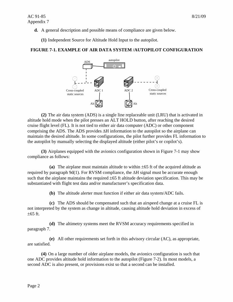
AC 91-85 8/21/09 Appendix 7
d. A general description and possible means of compliance are given below.
(1) Independent Source for Altitude Hold Input to the autopilot.
FIGURE 7-1. EXAMPLE OF AIR DATA SYSTEM /AUTOPILOT CONFIGURATION
autopilot
Cross-coupled static sources
Cross-coupled static sources
Alt Alt
ADS
18001800
ADC 2 ADC 1
(2) The air data system (ADS) is a single line replaceable unit (LRU) that is activated in altitude hold mode when the pilot presses an ALT HOLD button, after reaching the desired cruise flight level (FL). It is not tied to either air data computer (ADC) or other component comprising the ADS. The ADS provides ΔH information to the autopilot so the airplane can maintain the desired altitude. In some configurations, the pilot further provides FL information to the autopilot by manually selecting the displayed altitude (either pilot’s or copilot’s).
(3) Airplanes equipped with the avionics configuration shown in Figure 7-1 may show compliance as follows:
(a) The airplane must maintain altitude to within ±65 ft of the acquired altitude as required by paragraph 9d(1). For RVSM compliance, the ΔH signal must be accurate enough such that the airplane maintains the required ±65 ft altitude deviation specification. This may be substantiated with flight test data and/or manufacturer’s specification data.
(b) The altitude alerter must function if either air data system/ADC fails.
(c) The ADS should be compensated such that an airspeed change at a cruise FL is not interpreted by the system as change in altitude, causing altitude hold deviation in excess of ±65 ft.
(d) The altimetry systems meet the RVSM accuracy requirements specified in paragraph 7.
(e) All other requirements set forth in this advisory circular (AC), as appropriate, are satisfied.
(4) On a large number of older airplane models, the avionics configuration is such that one ADC provides altitude hold information to the autopilot (Figure 7-2). In most models, a second ADC is also present, or provisions exist so that a second can be installed.
Page 2
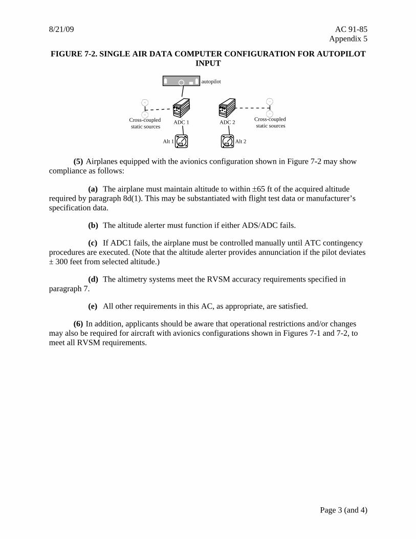
8/21/09 AC 91-85 Appendix 5
Page 3 (and 4)
FIGURE 7-2. SINGLE AIR DATA COMPUTER CONFIGURATION FOR AUTOPILOT INPUT
autopilot
Cross-coupled static sources
Cross-coupled static sources
Alt 1 Alt 2
ADC 2
1800 1800
ADC 1
(5) Airplanes equipped with the avionics configuration shown in Figure 7-2 may show compliance as follows:
(a) The airplane must maintain altitude to within ±65 ft of the acquired altitude required by paragraph 8d(1). This may be substantiated with flight test data or manufacturer’s specification data.
(b) The altitude alerter must function if either ADS/ADC fails.
(c) If ADC1 fails, the airplane must be controlled manually until ATC contingency procedures are executed. (Note that the altitude alerter provides annunciation if the pilot deviates ± 300 feet from selected altitude.)
(d) The altimetry systems meet the RVSM accuracy requirements specified in paragraph 7.
(e) All other requirements in this AC, as appropriate, are satisfied.
(6) In addition, applicants should be aware that operational restrictions and/or changes may also be required for aircraft with avionics configurations shown in Figures 7-1 and 7-2, to meet all RVSM requirements.