Embed Size (px)
Citation preview

Preliminaries for Motor Control
Chapter 1
AC Motor Control andEV Applications

Brush and Commutator
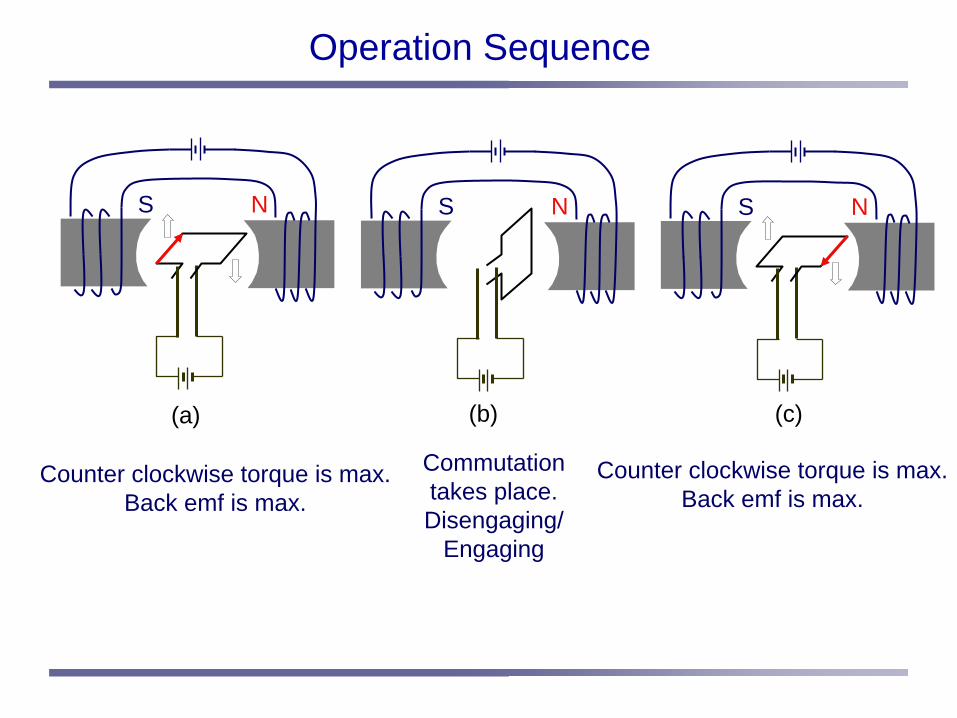
Operation Sequence
Counter clockwise torque is max.Back emf is max.
Counter clockwise torque is max.Back emf is max.
Commutationtakes place.Disengaging/
Engaging
(b)
S N
(a) (c)
S N S N
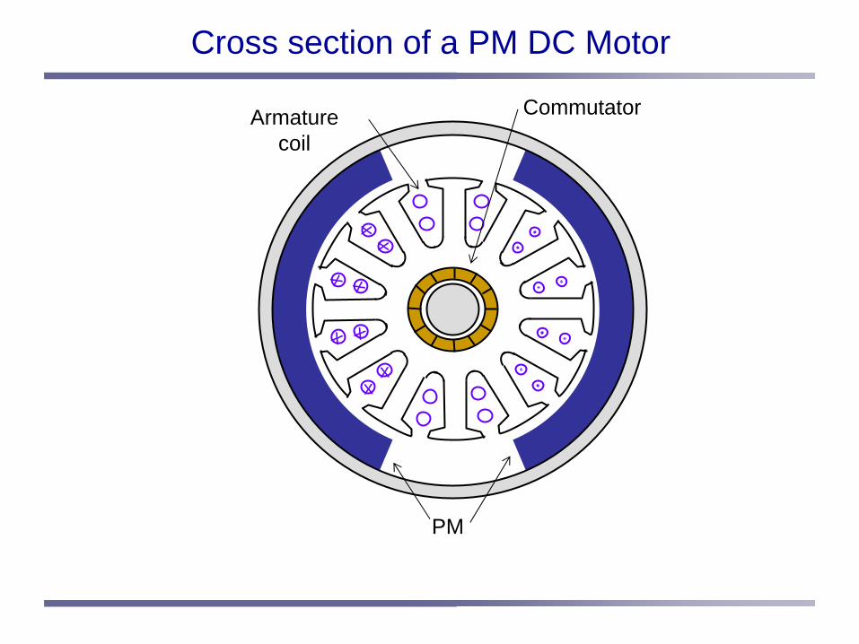
Cross section of a PM DC Motor
xx
x x
x x
xx
PM
CommutatorArmaturecoil
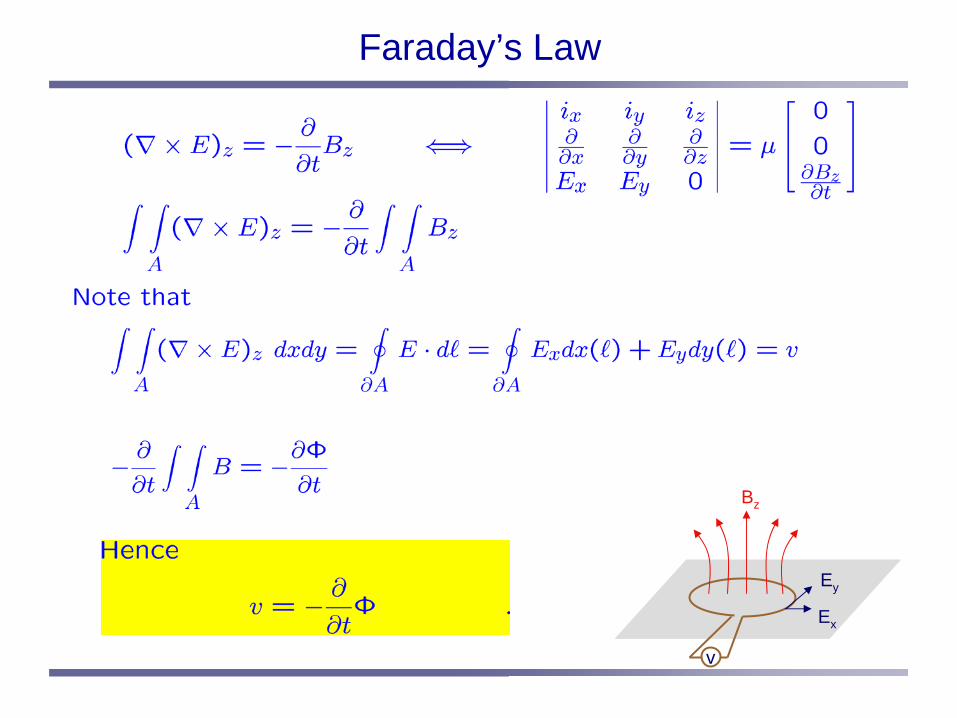
Faraday’s Law
v
Ex
Ey
Bz

Back EMF
As the armature winding rotates in the DC field,the amount of flux passing through the armature winding varies. Hence, the voltage is developed as the rotor rotates.The polarity is opposite to the direction of current flow when motoring.
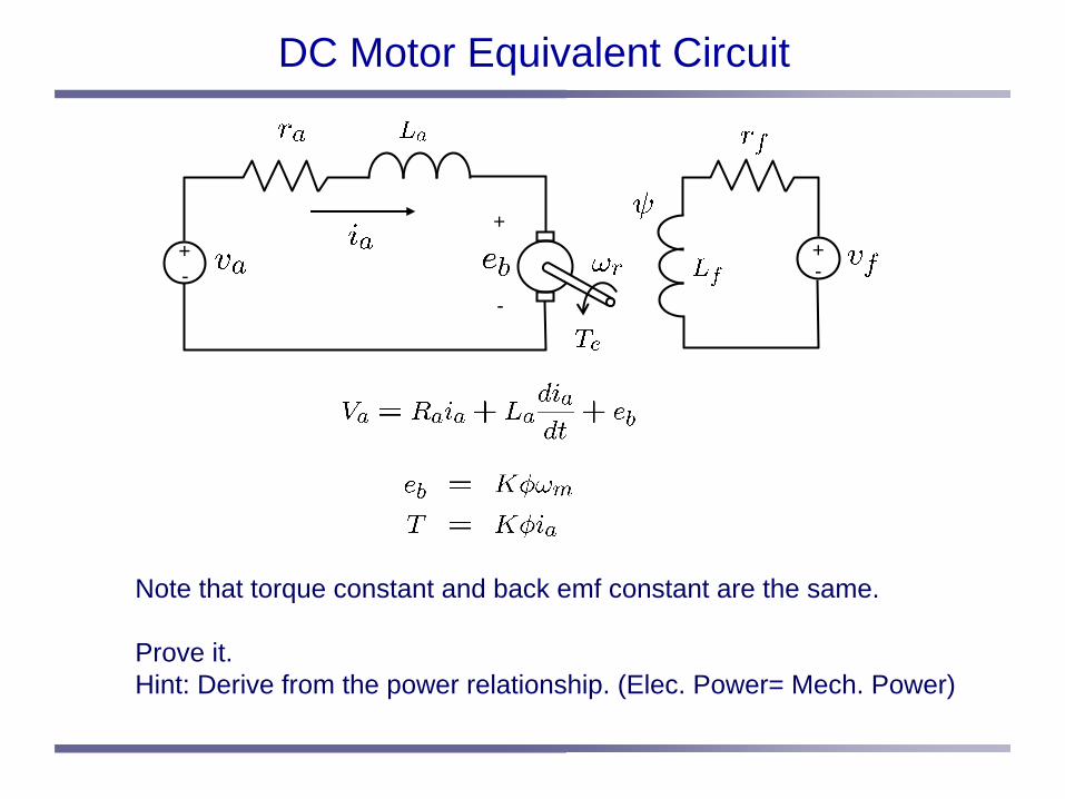
DC Motor Equivalent Circuit
Note that torque constant and back emf constant are the same.
Prove it.Hint: Derive from the power relationship. (Elec. Power= Mech. Power)
+-
+
-
+-
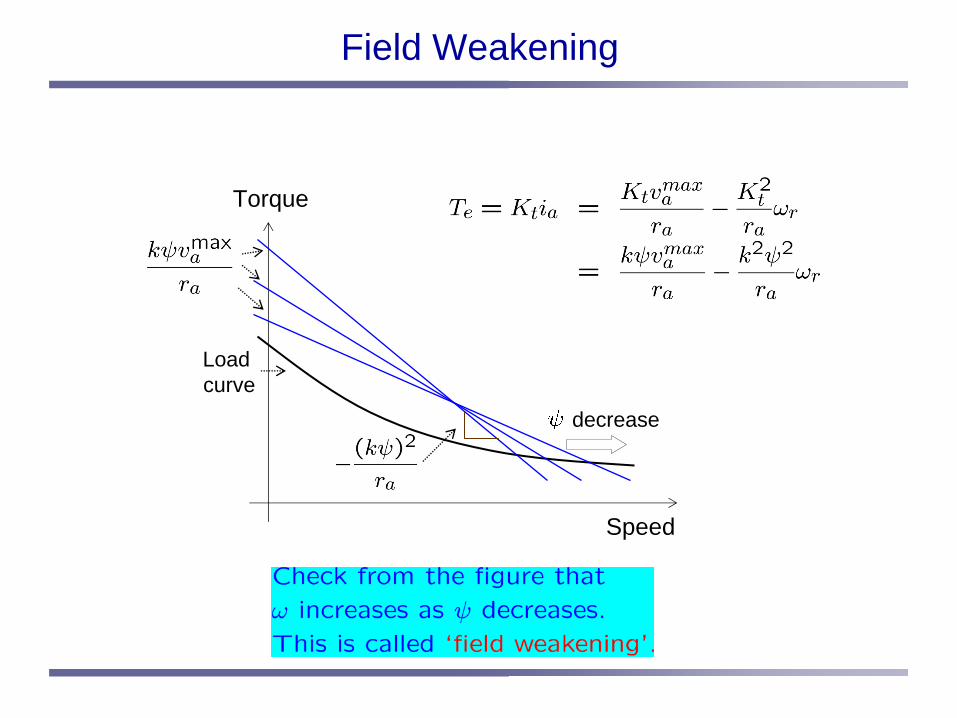
Field Weakening
Torque
Speed
decrease
Load curve

Power and Torque vs Speed
power
current
torque
ratedspeed
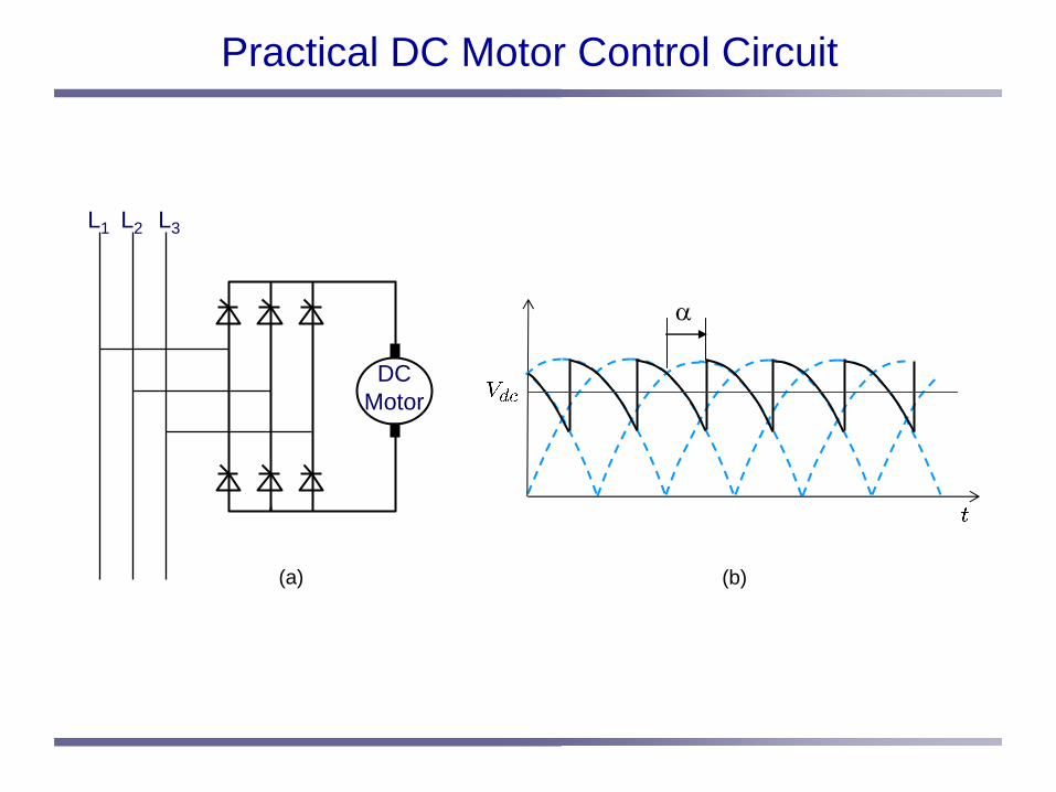
Practical DC Motor Control Circuit
DCMotor
L1 L2 L3
(a) (b)
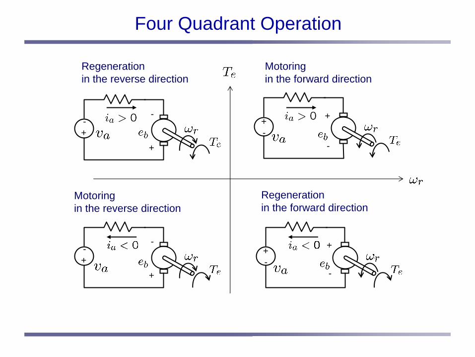
Four Quadrant Operation
Motoring in the forward direction
Regeneration in the reverse direction
Motoringin the reverse direction
Regenerationin the forward direction
+-
+
-+-
+
-
+-
+
-+-
+
-
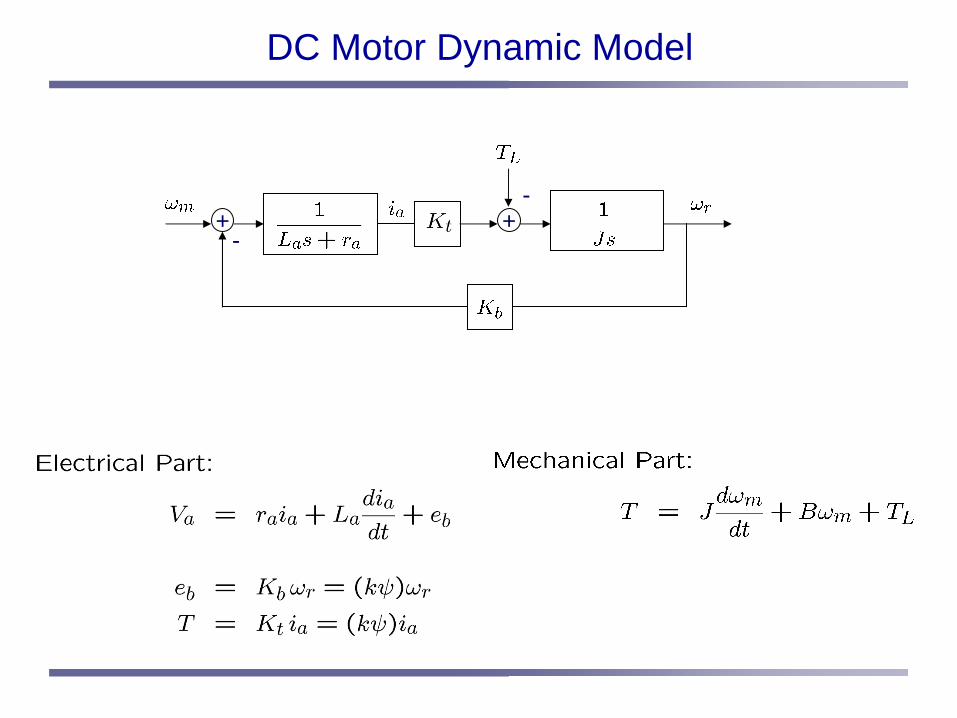
DC Motor Dynamic Model
++-
-

+
TL
PI+PI+ +-
--
DC Motor Speed Control Block Diagram
1. Determine current loop PI controller so that there is a slight overshoot to a step input.
2. Replace the current loop by 1. Determine velocity loop PI controller so that it is critically damped.
3. Find a response for step speed command *=1500rpm with load TL = 30 us (t-2).
-
Current Controller
++-
-
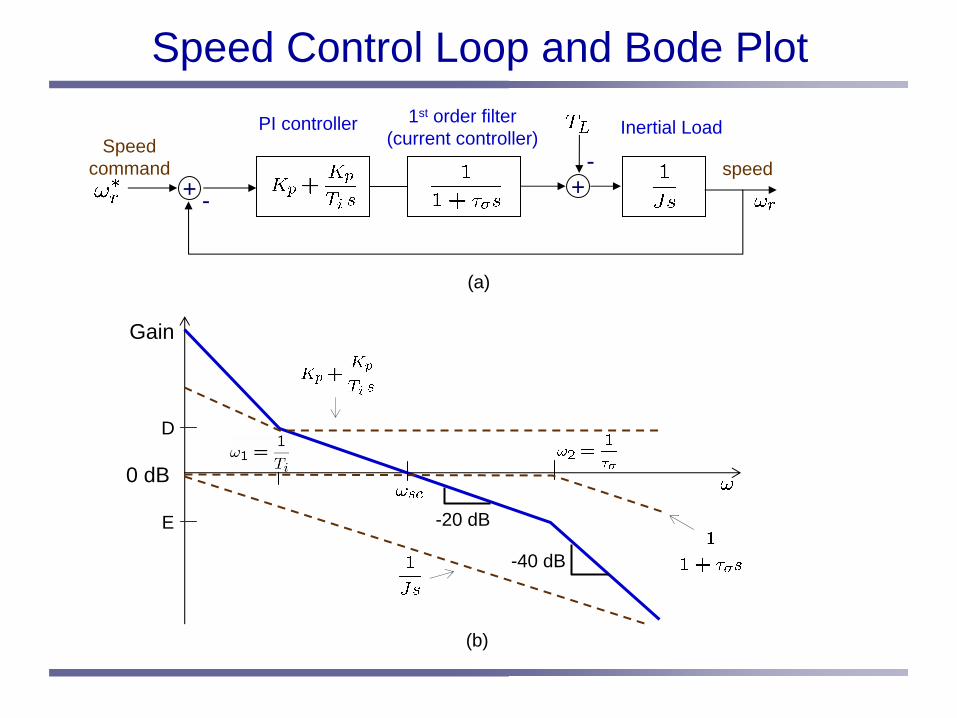
Speed Control Loop and Bode Plot
Gain
0 dB
-20 dB
PI controller 1st order filter(current controller) Inertial Load
speedSpeed
command
-40 dB
D
E
(a)
(b)

PI and IP Controllers
++-
-
PI controller
speedSpeed
command
++-
-
IP controller
speedSpeed
command+
-+
+
(a)
(b)
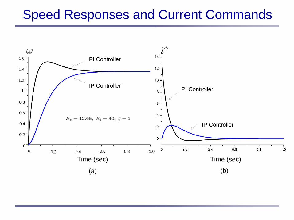
00 0.2 0.4 0.6 0.8 1.0
0.2
0.4
0.6
0.8
1
1.2
1.4
1.6
Time (sec)
PI Controller
IP Controller PI Controller
IP Controller
(a) (b)
Time (sec)
Speed Responses and Current Commands

PI Controller with Reference Model
-
-
Reference Model
Integral control
Proportionalcontrol
+
+
+++
++
+
+
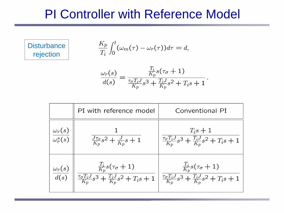
PI Controller with Reference Model
Disturbancerejection
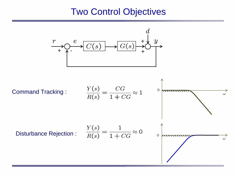
Two Control Objectives
-++
+
Command Tracking :
Disturbance Rejection :

Sensitivity and Complementary Sensitivity Functions
-++
+
Sensitivity andComplementary SensitivityFunctions

Instability Mechanism
-
Assumption
180o phase delay11
12
13
14
++
+

Gain Margin and Phase Margin
-180o
PhaseMargin
GainMargin
0
Gain crossover angular frequency
phase crossover angular frequency
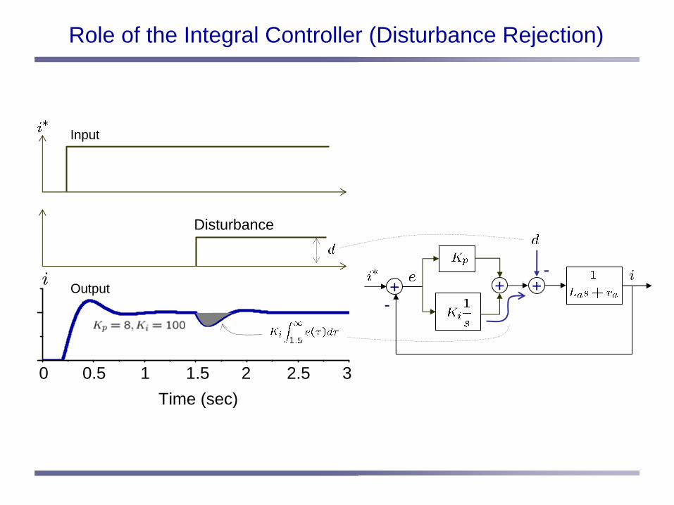
Input
Disturbance
Time (sec)
+-
-+ +Output
0 1 1.5 320.5 2.5
Role of the Integral Controller (Disturbance Rejection)
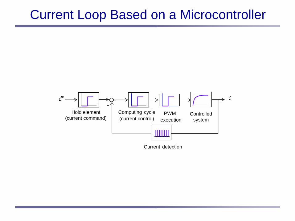
Current Loop Based on a Microcontroller
Hold element(current command)
-Computing cycle(current control)
Controlledsystem
Current detection
PWMexecution
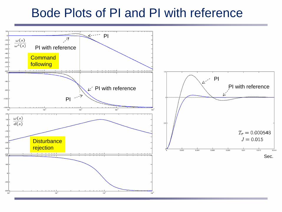
Bode Plots of PI and PI with referencePI
PI with reference
PI
PI with reference
Disturbancerejection
Commandfollowing
PIPI with reference
Sec.
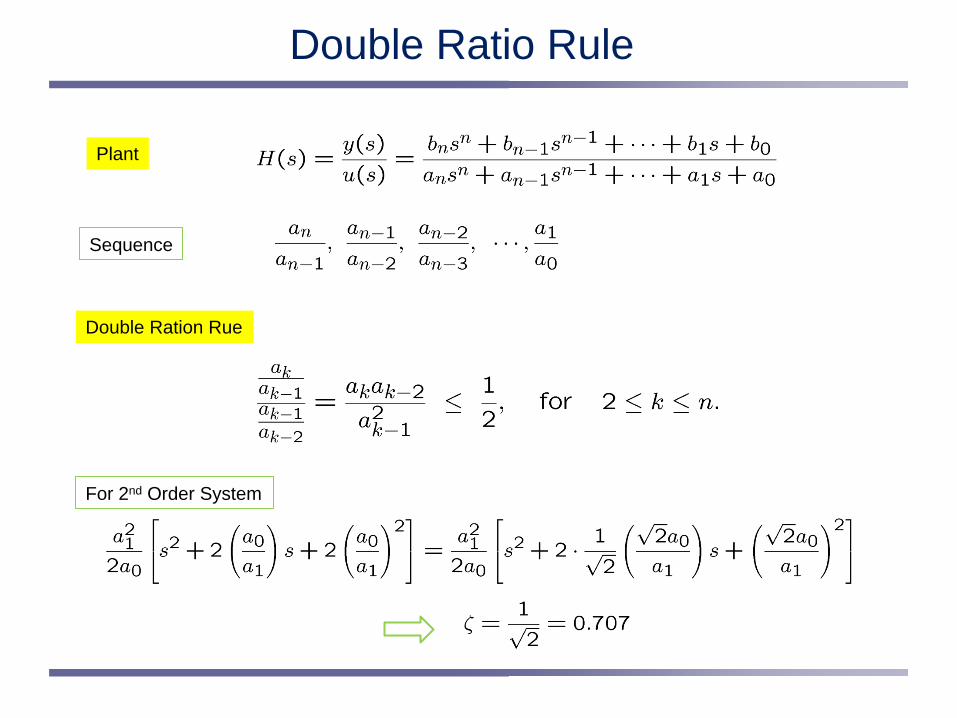
Double Ratio Rule
Sequence
Plant
Double Ration Rue
For 2nd Order System

Application of Double Ratio Rule
Double Ration Rue
For 2nd Order System
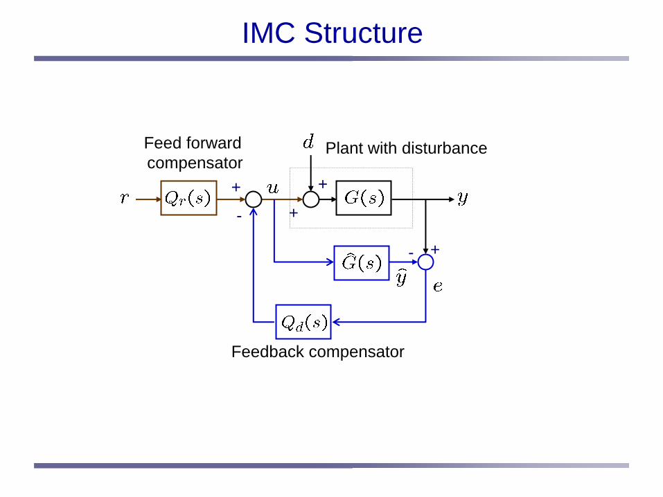
IMC Structure
-
-
Plant with disturbance
Feedback compensator
Feed forwardcompensator
+
+
++
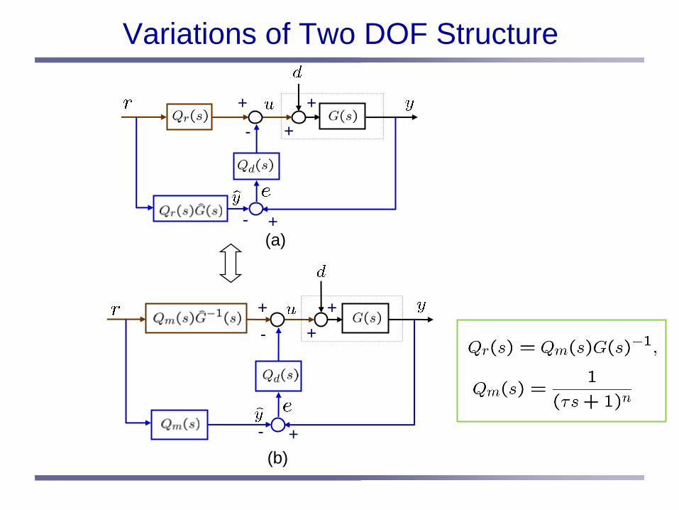
Variations of Two DOF Structure
-
-
(a)
(b)-
-
+ ++
+
++
+
+
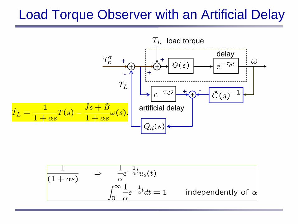
Load Torque Observer with an Artificial Delay
-
-
load torque
+
+
++
+
++
delay
artificial delay