Embed Size (px)
Citation preview

B AC Motors
B-23 AC Motors Induction Motor
Induction Motor 40W(□90mm)
1) Enter the phase & voltage code in the place * and enter the model type of attaching Gearbox in the box (□) within the motor model name.2) All models contain a built-in thermal protector.3) Gear Type Shaft is for attaching Gearbox and D-Cut & Key Type Shafts are for using motor only.
1) Enter the phase & voltage code in the box (□) within the motor model name.2) Enter the gear ratio in the box (□) within the Gearbox model name.3) A colored background indicates gear shaft rotation in the same direction as the motor shaft; a white background indicates rotation in the opposite direction.4) The rotating speed is calculated by dividing the motor’s synchronous speed (50Hz: 1,500r/min, 60Hz: 1,800r/min) by the gear ratio. The actual speed is 2~20% less than the displayed value,
depending on the size of the load.
40W Induction Motor40W(□90mm)
Model9IDG*-40□(-T): Gear Type Shaft9IDD*-40(-T): D-Cut Type Shaft9IDK*-40(-T): Key Type Shaft
Output
W
Voltage
V
Frequency
Hz
Poles Duty Starting Torque
kgfcm N.m
Rated LoadCapacitor
㎌ / VACSpeed
r/min
Current
A
Torque
kgfcm N.mLead Wire Type Terminal Box Type
9IDGA-40□ 9IDGA-40□-T 40 1ø110 60 4 Cont. 2.60 0.260 1600 0.80 2.80 0.280 10.0 / 250
9IDGD-40□ 9IDGD-40□-T 40 1ø220 60 4 Cont. 2.60 0.260 1600 0.39 2.80 0.280 2.5 / 450
9IDGE-40□ 9IDGE-40□-T 401ø220
50 4 Cont.1.80 0.180
13000.33 3.00 0.300
2.0 / 4501ø240 2.20 0.220 0.36 3.60 0.360
9IDGG-40□ 9IDGG-40□-T 40 3ø22050
4 Cont.9.00 0.900 1300 0.31 3.20 0.320
-60 7.40 0.740 1600 0.27 2.45 0.245
9IDGK-40□ 9IDGK-40□-T 40
3ø38050
4 Cont.9.00 0.900 1300 0.20 3.20 0.320
-
60 7.20 0.720 1550 0.18 2.80 0.280
3ø40050
4 Cont.10.00 1.000 1300 0.20 3.40 0.340
60 7.80 0.780 1550 0.18 3.00 0.300
3ø41550
4 Cont.11.00 1.100 1350 0.20 3.00 0.300
60 8.60 0.860 1600 0.18 2.80 0.280
3ø44050
4 Cont.12.00 1.200 1350 0.21 3.40 0.340
60 9.80 0.980 1600 0.19 3.00 0.300
60Hz
50Hz
Motor Model Gearbox Model
Gear Ratio 2 3 3.6 5 6 7.5 9 10 12.5 15 18 25 30 36 40 50 60 75 90 100 120 150 180 200
r/min 900 600 500 360 300 240 200 180 144 120 100 72 60 50 45 36 30 24 20 18 15 12 10 10
9IDG□-40G9GBK□BMH
kgfcm 4.6 7.0 8.4 11.6 13.9 17.4 20.9 23.2 29.1 34.9 37.8 52.5 63.0 68.5 76.2 95.2 100.0 100.0 100.0 100.0 100.0 100.0 100.0 100.0
N.m 0.46 0.68 0.82 1.14 1.37 1.71 2.05 2.28 2.85 3.42 3.70 5.15 6.17 6.72 7.46 9.33 9.80 9.80 9.80 9.80 9.80 9.80 9.80 9.80
Motor Model Gearbox Model
Gear Ratio 2 3 3.6 5 6 7.5 9 10 12.5 15 18 25 30 36 40 50 60 75 90 100 120 150 180 200
r/min 750 500 417 300 250 200 167 150 120 100 83 60 50 42 38 30 25 20 17 15 13 10 8 8
9IDG□-40G9GBK□BMH
kgfcm 5.6 8.5 10.2 14.1 16.9 21.2 25.4 28.2 35.3 42.3 45.9 63.8 76.5 83.2 92.5 100.0 100.0 100.0 100.0 100.0 100.0 100.0 100.0 100.0
N.m 0.55 0.83 1.00 1.38 1.66 2.07 2.49 2.77 3.46 4.15 4.50 6.25 7.50 8.16 9.06 9.80 9.80 9.80 9.80 9.80 9.80 9.80 9.80 9.80
Motor Model Gearbox ModelGear Ratio 10 12 15 18 25 30 36 50 60
r/min 180 150 120 100 72 60 50 36 30
9IDG□-40W9WD□BL/□BR/
□BRL
kgfcm 23.0 26.9 32.3 37.3 49.0 55.4 64.5 84.0 92.4
N.m 2.25 2.63 3.17 3.66 4.80 5.43 6.32 8.23 9.06
Motor Model Gearbox ModelGear Ratio 10 12 15 18 25 30 36 50 60
r/min 150 125 100 83 60 50 42 30 25
9IDG□-40W9WD□BL/□BR/
□BRL
kgfcm 27.9 32.6 39.3 45.3 59.5 67.3 78.3 102.0 112.2
N.m 2.73 3.20 3.85 4.44 5.83 6.60 7.68 10.00 11.00
Motor Specification
Max. Permissible Torque at Output Shaft of Gearbox

DKM AC/DC Geared Motor and Gearbox B-24
Inductio
n Mo
tor 40W
( □90m
m)
Dimensions

B AC Motors
Lead Wire Type Terminal Box Type
1) The direction of motor rotation is as viewed from the shaft end of the motor.2) CW represents the clockwise direction, while CCW represents the counterclockwise direction.3) Change the direction of single phase motor rotation only after bringing the motor to a stop. If an attempt is made to change the direction of rotation while the motor is rotating,
the motor may ignore the reversing command or change its direction after some delay.
Connection Diagrams
B-25 AC Motors Induction Motor
9IDD□-40 9IDD□-40-T 9IDG□-40G+9GBK□BMH 9IDG□-40W+9WD□BL
Motor Images
Induction Motor 40W(□90mm)

DKM AC/DC Geared Motor and Gearbox B-26
9IDD□-40 9IDD□-40-T 9IDG□-40G+9GBK□BMH 9IDG□-40W+9WD□BL
Inductio
n Mo
tor 60W
( □90m
m)
Model9IDG*-60F□(-T): Gear Type Shaft9IDD*-60F(-T): D-Cut Type Shaft9IDK*-60F(-T): Key Type Shaft
Output
W
Voltage
V
Frequency
Hz
Poles Duty Starting Torque
kgfcm N.m
Rated Load
Capacitor
㎌ / VACSpeed
r/min
Current
A
Torque
kgfcm N.mLead Wire Type Terminal Box Type
9IDGA-60F□ 9IDGA-60F□-T 60 1ø110 60 4 Cont. 3.40 0.340 1600 1.40 4.60 0.460 16.0 / 250
9IDGD-60F□ 9IDGD-60F□-T 60 1ø220 60 4 Cont. 4.20 0.420 1600 0.63 4.60 0.460 4.0 / 450
9IDGE-60F□ 9IDGE-60F□-T 601ø220
50 4 Cont.3.40 0.340
13000.48 4.80 0.480
3.5 / 4501ø240 4.00 0.400 0.54 5.40 0.540
9IDGG-60F□ 9IDGG-60F□-T 60 3ø22050
4 Cont.15.00 1.500 1350 0.59 4.60 0.460
-60 12.80 1.280 1600 0.49 4.20 0.420
9IDGK-60F□ 9IDGK-60F□-T 60
3ø38050
4 Cont.17.00 1.700 1350 0.33 4.80 0.480
-
60 13.80 1.380 1600 0.29 4.60 0.460
3ø40050
4 Cont.18.60 1.860 1350 0.36 5.20 0.520
60 15.20 1.520 1600 0.30 5.00 0.500
3ø41550
4 Cont.20.00 2.000 1350 0.40 5.60 0.560
60 16.20 1.620 1600 0.33 5.20 0.520
3ø44050
4 Cont.22.00 2.200 1350 0.44 6.00 0.600
60 18.20 1.820 1600 0.36 5.80 0.580
60Hz
50Hz
1) Enter the phase & voltage code in the place * and enter the model type of attaching Gearbox in the box (□) within the motor model name.2) All models contain a built-in thermal protector.3) Gear Type Shaft is for attaching Gearbox and D-Cut & Key Type Shafts are for using motor only.
1) Enter the phase & voltage code in the box (□) within the motor model name. 2) Enter the gear ratio in the box (□) within the Gearbox model name.3) A colored background indicates gear shaft rotation in the same direction as the motor shaft; a white background indicates rotation in the opposite direction.4) The rotating speed is calculated by dividing the motor’s synchronous speed (50Hz: 1,500r/min, 60Hz: 1,800r/min) by the gear ratio. The actual speed is 2~20% less than the displayed value,
depending on the size of the load.
60W Induction Motor60W(□90mm)
Motor Model
Gearbox Model
Gear Ratio 2 3 3.6 5 6 7.5 9 12.5 15 18 20 25 30 36 40 50 60 75 90 100 120 150 180 200
r/min 900 600 500 360 300 240 200 144 120 100 90 72 60 50 45 36 30 24 20 18 15 12 10 9
9IDG□-60FP
9PBK□BH9PFK□BH
kgfcm 7.0 10.5 12.5 17.4 20.9 26.1 31.4 39.4 47.3 56.7 57.1 71.4 85.7 102.8 114.2 142.8 171.4 192.2 200.0 200.0 200.0 200.0 200.0 200.0
N.m 0.68 1.02 1.23 1.71 2.05 2.56 3.07 3.86 4.63 5.56 5.60 7.00 8.40 10.08 11.20 13.99 16.79 18.83 19.60 19.60 19.60 19.60 19.60 19.60
9IDG□-60FH
9HBK□BH9HFK□BH
kgfcm-
10.5 12.5 -
20.9 -
31.4 39.4 47.3 56.7 57.1 71.4 85.7 102.8 -
142.8 171.4 192.2 230.6 256.2 300.0 300.0 300.0 300.0
N.m 1.02 1.23 2.05 3.07 3.86 4.63 5.56 5.60 7.00 8.40 10.08 13.99 16.79 18.83 22.60 25.11 29.40 29.40 29.40 29.40
Motor Model
Gearbox Model
Gear Ratio 2 3 3.6 5 6 7.5 9 12.5 15 18 20 25 30 36 40 50 60 75 90 100 120 150 180 200
r/min 750 500 417 300 250 200 167 120 100 83 75 60 50 42 38 30 25 20 17 15 13 10 8 7.5
9IDG□-60FP
9PBK□BH9PFK□BH
kgfcm 8.6 12.9 15.5 21.6 25.9 32.4 38.8 48.8 58.5 70.2 70.7 88.4 106.1 127.3 141.4 176.8 200.0 200.0 200.0 200.0 200.0 200.0 200.0 200.0
N.m 0.85 1.27 1.52 2.11 2.54 3.17 3.81 4.78 5.73 6.88 6.93 8.66 10.40 12.48 13.86 17.33 19.60 19.60 19.60 19.60 19.60 19.60 19.60 19.60
9IDG□-60FH
9HBK□BH9HFK□BH
kgfcm-
12.9 15.5 -
25.9 -
38.8 48.8 58.5 70.2 70.7 88.4 106.1 127.3 -
176.8 212.2 237.9 285.5 300.0 300.0 300.0 300.0 300.0
N.m 1.27 1.52 2.54 3.81 4.78 5.73 6.88 6.93 8.66 10.40 12.48 17.33 20.79 23.31 27.98 29.40 29.40 29.40 29.40 29.40
Motor Model Gearbox Model
Gear Ratio 10 12 15 18 25 30 36 50 60
r/min 180 150 120 100 72 60 50 36 30
9IDG□-60FW9WD□BL/□BR/□BRL
kgfcm 34.4 40.3 48.5 55.9 73.5 83.2 96.8 126.0 122.4
N.m 3.38 3.95 4.75 5.48 7.20 8.15 9.48 12.35 12.00
Motor Model Gearbox Model
Gear Ratio 10 12 15 18 25 30 36 50 60
r/min 150 125 100 83 60 50 42 30 25
9IDG□-60FW9WD□BL/□BR/□BRL
kgfcm 42.6 49.9 60.1 69.3 91.0 103.0 119.8 142.9 122.4
N.m 4.18 4.89 5.89 6.79 8.92 10.09 11.74 14.00 12.00
Motor Model
Gearbox Model
Gear Ratio 7.5 10 15 20 25 30 40 50 60 80
r/min 240 180 120 90 72 60 45 36 30 22
9IDG□-60FWH
9WHD□-030
kgfcm 26.5 34.0 47.9 60.5 69.3 80.6 99.1 113.4 126.0 132.7
N.m 2.59 3.33 4.69 5.93 6.79 7.90 9.71 11.11 12.35 13.00
Motor Model
Gearbox Model
Gear Ratio 7.5 10 15 20 25 30 40 50 60 80
r/min 200 150 100 75 60 50 38 30 25 18
9IDG□-60FWH
9WHD□-030
kgfcm 32.8 42.1 59.3 74.9 85.8 99.8 122.7 140.4 156.0 132.7
N.m 3.21 4.13 5.81 7.34 8.41 9.78 12.03 13.76 15.29 13.00
Induction Motor 60W(□90mm)
Motor Specification
Max. Permissible Torque at Output Shaft of Gearbox

B AC Motors
B-27 AC Motors Induction Motor
Dimensions
Induction Motor 60W(□90mm)

DKM AC/DC Geared Motor and Gearbox B-28
Inductio
n Mo
tor 60W
( □90m
m)
9IDD□-60F 9IDD□-60F-T 9IDG□-60FP+9PBK□BH 9IDG□-60FP+9PFK□BH
9IDG□-60FH+9HBK□BH 9IDG□-60FH+9HFK□BH 9IDG□-60FW+9WD□BL 9IDG□-60FWH+9WHD□-030
Motor Images

B AC Motors
B-29 AC Motors Induction Motor
Induction Motor 60W(□90mm)
Lead Wire Type Terminal Box Type
1) The direction of motor rotation is as viewed from the shaft end of the motor.2) CW represents the clockwise direction, while CCW represents the counterclockwise direction.3) Change the direction of single phase motor rotation only after bringing the motor to a stop. If an attempt is made to change the direction of rotation while the motor is rotating,
the motor may ignore the reversing command or change its direction after some delay.
Connection Diagrams

DKM AC/DC Geared Motor and Gearbox B-30
Inductio
n Mo
tor 6 0W
(90mm
)Ind
uction M
oto
r 90W( □
90mm
)
Model9IDG*-90F□(-T): Gear Type Shaft9IDD*-90F(-T): D-Cut Type Shaft9IDK*-90F(-T): Key Type Shaft
Output
W
Voltage
V
Frequency
Hz
Poles Duty Starting Torque
kgfcm N.m
Rated LoadCapacitor
㎌ / VACSpeed
r/min
Current
A
Torque
kgfcm N.mLead Wire Type Terminal Box Type
9IDGA-90F□ 9IDGA-90F□-T 90 1ø110 60 4 Cont. 5.00 0.500 1600 1.90 6.20 0.620 20.0 / 250
9IDGD-90F□ 9IDGD-90F□-T 90 1ø220 60 4 Cont. 5.20 0.520 1600 0.90 6.20 0.620 5.0 / 450
9IDGE-90F□ 9IDGE-90F□-T 901ø220
50 4 Cont.5.00 0.500
13000.70 7.40 0.740
5.0 / 4501ø240 6.00 0.600 0.76 8.60 0.860
9IDGG-90F□ 9IDGG-90F□-T 90 3ø22050
4 Cont.20.00 2.000 1300 0.66 7.80 0.780
-60 16.60 1.660 1600 0.55 5.80 0.580
9IDGK-90F□ 9IDGK-90F□-T 90
3ø38050
4 Cont.21.80 2.180 1300 0.40 7.80 0.780
-
60 17.20 1.720 1600 0.33 5.80 0.580
3ø40050
4 Cont.24.00 2.400 1300 0.43 8.60 0.860
60 19.20 1.920 1600 0.36 6.20 0.620
3ø41550
4 Cont.26.00 2.600 1350 0.43 7.40 0.740
60 20.20 2.020 1600 0.37 6.80 0.680
3ø44050
4 Cont.29.00 2.900 1350 0.48 8.00 0.800
60 23.80 2.380 1650 0.37 6.00 0.600
60Hz
50Hz
1) Enter the phase & voltage code in the place * and enter the model type of attaching Gearbox in the box (□) within the motor model name.2) All models contain a built-in thermal protector.3) Gear Type Shaft is for attaching Gearbox and D-Cut & Key Type Shafts are for using motor only.
1) Enter the phase & voltage code in the box (□) within the motor model name. 2) Enter the gear ratio in the box (□) within the Gearbox model name.3) A colored background indicates gear shaft rotation in the same direction as the motor shaft; a white background indicates rotation in the opposite direction.4) The rotating speed is calculated by dividing the motor’s synchronous speed (50Hz: 1,500r/min, 60Hz: 1,800r/min) by the gear ratio. The actual speed is 2~20% less than the displayed value,
depending on the size of the load.
90W Induction Motor90W(□90mm)
Motor Model
Gearbox Model
Gear Ratio 2 3 3.6 5 6 7.5 9 12.5 15 18 20 25 30 36 40 50 60 75 90 100 120 150 180 200
r/min 900 600 500 360 300 240 200 144 120 100 90 72 60 50 45 36 30 24 20 18 15 12 10 9
9IDG□-90FP
9PBK□BH9PFK□BH
kgfcm 10.3 15.4 18.5 25.7 30.9 38.6 46.3 58.1 69.8 83.7 84.3 105.4 126.5 151.8 168.6 200.0 200.0 200.0 200.0 200.0 200.0 200.0 200.0 200.0
N.m 1.01 1.51 1.82 2.52 3.03 3.78 4.54 5.70 6.84 8.20 8.26 10.33 12.40 14.87 16.53 19.60 19.60 19.60 19.60 19.60 19.60 19.60 19.60 19.60
9IDG□-90FH
9HBK□BH9HFK□BH
kgfcm-
15.4 18.5 -
30.9 -
46.3 58.1 69.8 83.7 84.3 105.4 126.5 151.8 -
210.8 253.0 300.0 300.0 300.0 300.0 300.0 300.0 300.0
N.m 1.51 1.82 3.03 4.54 5.70 6.84 8.20 8.26 10.33 12.40 14.87 20.66 24.79 29.40 29.40 29.40 29.40 29.40 29.40 29.40
Motor Model
Gearbox Model
Gear Ratio 2 3 3.6 5 6 7.5 9 12.5 15 18 20 25 30 36 40 50 60 75 90 100 120 150 180 200
r/min 750 500 417 300 250 200 167 120 100 83 75 60 50 42 38 30 25 20 17 15 13 10 8 7.5
9IDG□-90FP
9PBK□BH9PFK□BH
kgfcm 12.3 18.4 22.1 30.7 36.9 46.1 55.3 69.4 83.3 99.9 100.6 125.8 151.0 181.2 200.0 200.0 200.0 200.0 200.0 200.0 200.0 200.0 200.0 200.0
N.m 1.20 1.81 2.17 3.01 3.61 4.51 5.42 6.80 8.16 9.79 9.86 12.33 14.79 17.75 19.60 19.60 19.60 19.60 19.60 19.60 19.60 19.60 19.60 19.60
9IDG□-90FH
9HBK□BH9HFK□BH
kgfcm-
18.4 22.1 -
36.9 -
55.3 69.4 83.3 99.9 100.6 125.8 151.0 181.2 -
251.6 300.0 300.0 300.0 300.0 300.0 300.0 300.0 300.0
N.m 1.81 2.17 3.61 5.42 6.80 8.16 9.79 9.86 12.33 14.79 17.75 24.66 29.40 29.40 29.40 29.40 29.40 29.40 29.40 29.40
Motor Model
Gearbox Model
Gear Ratio 10 12 15 18 25 30 36 50 60
r/min 180 150 120 100 72 60 50 36 30
9IDG□-90FW
9WD□BL/□BR/□BRL
kgfcm 50.8 59.5 71.6 82.6 108.5 122.8 153.1 142.9 122.4
N.m 4.98 5.83 7.02 8.08 10.63 12.03 15.00 14.00 12.00
Motor Model
Gearbox Model
Gear Ratio 10 12 15 18 25 30 36 50 60
r/min 150 125 100 83 60 50 42 30 25
9IDG□-90FW
9WD□BL/□BR/□BRL
kgfcm 60.7 71.0 85.5 98.6 129.5 146.5 153.1 142.9 122.4
N.m 5.95 6.96 8.38 9.66 12.69 14.36 15.00 14.00 12.00
Motor Model
Gearbox Model
Gear Ratio 7.5 10 15 20 25 30 40 50 60 80
r/min 240 180 120 90 72 60 45 36 30 22
9IDG□-90FWH
9WHD□-030
kgfcm 39.1 50.2 70.7 89.3 102.3 119.0 146.3 173.5 163.3 132.7
N.m 3.83 4.92 6.93 8.75 10.03 11.67 14.34 17.00 16.00 13.00
Motor Model
Gearbox Model
Gear Ratio 7.5 10 15 20 25 30 40 50 60 80
r/min 200 150 100 75 60 50 38 30 25 18
9IDG□-90FWH
9WHD□-030
kgfcm 46.6 59.9 84.4 106.6 122.1 142.1 174.6 173.5 163.3 132.7
N.m 4.57 5.87 8.27 10.44 11.97 13.92 17.11 17.00 16.00 13.00
Induction Motor 90W(□90mm)
Motor Specification
Max. Permissible Torque at Output Shaft of Gearbox

B AC Motors
B-31 AC Motors Induction Motor
Dimensions
Induction Motor 90W(□90mm)

DKM AC/DC Geared Motor and Gearbox B-32
Inductio
n Mo
tor 90W
( □90m
m)
9IDD□-90F 9IDD□-90F-T 9IDG□-90FP+9PBK□BH 9IDG□-90FP+9PFK□BH
9IDG□-90FH+9HBK□BH 9IDG□-90FH+9HFK□BH 9IDG□-90FW+9WD□BL 9IDG□-90FWH+9WHD□-030
Motor Images
B AC Motors
B-33 AC Motors Induction Motor
Induction Motor 90W(□90mm)
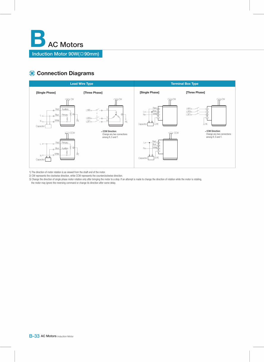
Lead Wire Type Terminal Box Type
1) The direction of motor rotation is as viewed from the shaft end of the motor.2) CW represents the clockwise direction, while CCW represents the counterclockwise direction.3) Change the direction of single phase motor rotation only after bringing the motor to a stop. If an attempt is made to change the direction of rotation while the motor is rotating,
the motor may ignore the reversing command or change its direction after some delay.
Connection Diagrams

DKM AC/DC Geared Motor and Gearbox B-34
Induction Motor 120W
( □90m
m)
Induction Motor 120W(□90mm)
Model9IDG*-120F□(-T): Gear Type Shaft9IDD*-120F(-T): D-Cut Type Shaft9IDK*-120F(-T): Key Type Shaft
Output
W
Voltage
V
Frequency
Hz
Poles Duty Starting Torque
kgfcm N.m
Rated LoadCapacitor
㎌ / VACSpeed
r/min
Current
A
Torque
kgfcm N.mLead Wire Type Terminal Box Type
9IDGA-120F□ 9IDGA-120F□-T 120 1ø110 60 4 Cont. 6.60 0.660 1600 2.00 7.40 0.740 25.0 / 250
9IDGD-120F□ 9IDGD-120F□-T 120 1ø220 60 4 Cont. 6.00 0.600 1600 1.00 7.60 0.760 6.0 / 450
9IDGE-120F□ 9IDGE-120F□-T 1201ø220
50 4 Cont.6.60 0.660
12500.90 9.40 0.940
6.5 / 4501ø240 8.00 0.800 1.00 10.20 1.020
9IDGG-120F□ 9IDGG-120F□-T 120 3ø22050
4 Cont.22.00 2.200 1300 0.82 9.20 0.920
-60 20.00 2.000 1550 0.78 7.80 0.780
9IDGK-120F□ 9IDGK-120F□-T 120
3ø38050
4 Cont.25.00 2.500 1300 0.48 9.00 0.900
-
60 20.00 2.000 1550 0.43 8.00 0.800
3ø40050
4 Cont.27.40 2.740 1300 0.53 9.80 0.980
60 21.80 2.180 1550 0.45 8.60 0.860
3ø41550
4 Cont.29.80 2.980 1300 0.57 10.00 1.000
60 23.80 2.380 1600 0.44 7.80 0.780
3ø44050
4 Cont.32.00 3.200 1350 0.64 8.80 0.880
60 26.80 2.680 1600 0.48 8.60 0.860
60Hz
50Hz
1) Enter the phase & voltage code in the place * and enter the model type of attaching Gearbox in the box (□) within the motor model name.2) All models contain a built-in thermal protector.3) Gear Type Shaft is for attaching Gearbox and D-Cut & Key Type Shafts are for using motor only.
1) Enter the phase & voltage code in the box (□) within the motor model name.2) Enter the gear ratio in the box (□) within the Gearbox model name.3) A colored background indicates gear shaft rotation in the same direction as the motor shaft; a white background indicates rotation in the opposite direction.4) The rotating speed is calculated by dividing the motor’s synchronous speed (50Hz: 1,500r/min, 60Hz: 1,800r/min) by the gear ratio. The actual speed is 2~20% less than the displayed value,
depending on the size of the load.
120W Induction Motor120W(□90mm)
Motor Model
Gearbox Model
Gear Ratio 2 3 3.6 5 6 7.5 9 12.5 15 18 20 25 30 36 40 50 60 75 90 100 120 150 180 200
r/min 900 600 500 360 300 240 200 144 120 100 90 72 60 50 45 36 30 24 20 18 15 12 10 9
9IDG□-120FP
9PBK□BH9PFK □BH
kgfcm 12.6 18.9 22.7 31.5 37.8 47.3 56.8 71.3 85.5 102.6 103.4 129.2 155.0 186.0 200.0 200.0 200.0 200.0 200.0 200.0 200.0 200.0 200.0 200.0
N.m 1.24 1.85 2.23 3.09 3.71 4.64 5.56 6.98 8.38 10.05 10.13 12.66 15.19 18.23 19.60 19.60 19.60 19.60 19.60 19.60 19.60 19.60 19.60 19.60
9IDG□-120FH
9HBK□BH9HFK□BH
kgfcm-
18.9 22.7 -
37.8 -
56.8 71.3 85.5 102.6 103.4 129.2 155.0 186.0 -
258.4 300.0 300.0 300.0 300.0 300.0 300.0 300.0 300.0
N.m 1.85 2.23 3.71 5.56 6.98 8.38 10.05 10.13 12.66 15.19 18.23 25.32 29.40 29.40 29.40 29.40 29.40 29.40 29.40 29.40
Motor Model
Gearbox Model
Gear Ratio 2 3 3.6 5 6 7.5 9 12.5 15 18 20 25 30 36 40 50 60 75 90 100 120 150 180 200
r/min 750 500 417 300 250 200 167 120 100 83 75 60 50 42 38 30 25 20 17 15 13 10 8 7.5
9IDG□-120FP
9PBK□BH9PFK□BH
kgfcm 16.3 24.4 29.3 40.7 48.8 61.0 73.2 101.7 122.0 146.4 162.7 200.0 200.0 200.0 200.0 200.0 200.0 200.0 200.0 200.0 200.0 200.0 200.0 200.0
N.m 1.59 2.39 2.87 3.99 4.78 5.98 7.17 9.96 11.96 14.35 15.94 19.60 19.60 19.60 19.60 19.60 19.60 19.60 19.60 19.60 19.60 19.60 19.60 19.60
9IDG□-120FH
9HBK□BH9HFK□BH
kgfcm 24.4 29.3 48.8 -
73.2 91.9 110.3 132.3 133.3 166.6 199.9 239.9 -
300.0 300.0 300.0 300.0 300.0 300.0 300.0 300.0 300.0
N.m 2.39 2.87 4.78 7.17 9.00 10.80 12.97 13.06 16.33 19.59 23.51 29.40 29.40 29.40 29.40 29.40 29.40 29.40 29.40 29.40
Motor Model
Gearbox Model
Gear Ratio 10 12 15 18 25 30 36 50 60
r/min 180 150 120 100 72 60 50 36 30
9IDG□-120FW
9WD□BL/□BR/□BRL
kgfcm 62.3 73.0 87.8 101.2 133.0 150.5 153.1 142.9 122.4
N.m 6.11 7.15 8.60 9.92 13.03 14.75 15.00 14.00 12.00
Motor Model
Gearbox Model
Gear Ratio 10 12 15 18 25 30 36 50 60
r/min 150 125 100 83 60 50 42 30 25
9IDG□-90FW
9WD□BL/□BR/□BRL
kgfcm 80.4 94.1 113.2 130.5 142.9 163.3 153.1 142.9 122.4
N.m 7.88 9.22 11.09 12.79 14.00 16.00 15.00 14.00 12.00
Motor Model
Gearbox Model
Gear Ratio 7.5 10 15 20 25 30 40 50 60 80
r/min 240 180 120 90 72 60 45 36 30 22
9IDG□-120FWH
9WHD□-030
kgfcm 47.9 61.6 86.6 109.4 125.4 145.9 179.4 173.5 163.3 132.7
N.m 4.69 6.03 8.49 10.73 12.29 14.30 17.58 17.00 16.00 13.00
Motor Model
Gearbox Model
Gear Ratio 7.5 10 15 20 25 30 40 50 60 80
r/min 200 150 100 75 60 50 38 30 25 18
9IDG□-120FWH
9WHD□-030
kgfcm 61.7 79.4 111.7 141.1 161.7 188.2 183.7 173.5 163.3 132.7
N.m 6.05 7.78 10.95 13.83 15.85 18.44 18.00 17.00 16.00 13.00
Motor Specification
Max. Permissible Torque at Output Shaft of Gearbox