Embed Size (px)
Citation preview
WBSETCL / TECH SPEC / Rev.-4 Page 1 of 20 ACDB (GIS SS)
AC POWER DISTRIBUTION
SWITCH BOARD
(for GIS Sub-Stations)
September 2017
Engineering Department
WEST BENGAL STATE ELECTRICITY TRANSMISSION COMPANY LIMITED
Regd. Office: VidyutBhawan, Block – DJ, Sector-II, Bidhannagar, Kolkata – 700091.
CIN: U40101WB2007SGC113474; Website: www.wbsetcl.in
WBSETCL / TECH SPEC / Rev.-4 Page 2 of 20 ACDB (GIS SS)
TECHNICAL SPECIFICATION OF 400/230 V AC
POWER DISTRIBUTION SWITCH BOARDS
1. SCOPE :
This specification covers design, manufacture, assembly, testing at the manufacturer’s works,
of indoor type 415/230 Volts AC switch boards for the GIS sub-stations as per approved schemes.
2. STANDARDS :
The equipment covered by this specification shall, unless otherwise specified, be in accordance with, relevant IS specification. The degree of protection shall not be less than IP-
52 mentioned in IS-2147 and IP-42 as per IS:2447 in case of bus bar chambers where
continuous bus bar rating exceeds 1000 Amps.
3. I) DEVIATION :
Normally the offer should be as per Technical Specification without any deviation.
II) MODIFICATION :
If any modification felt necessary to improve performance, efficiency and utility of equipment,
the same must be mentioned in the 'Modification schedule' with reasons duly supported by
documentary evidences and advantages. Such modifications suggested may or may not be accepted, but the same must be submitted along with Pre-Bid Queries. The modifications not
mentioned in Schedule will not be considered.
4. DESIGN CRITERIA :
a. In case of 400KV sub-station, AC source shall be supplied separately from LT side of 2
numbers 630 KVA, 33/0.415 KV station service transformers.
b. In case of 220KV sub-station AC source shall be taken separately from LT side of 2nos.
315KVA, 33/0.415KV station service transformers through Cables.
c. In case of 132KV sub-station AC source shall be taken separately from LT side of 2nos. 100KVA, 33/0.415KV station service transformers through Cables.
d. The maximum loss component shall be guided as per relevant IS / IEC.
4.1. The AC-Distribution System shall be consists of separate panels designated as
(i) MAIN ACDB WITH DG (if applicable)
(ii) MAIN LIGTING DISTRIBUTION BOARD (MLDB) (iii) SUB DBs
All the above AC Panels shall be interconnected as per approved scheme layout.
WBSETCL / TECH SPEC / Rev.-4 Page 3 of 20 ACDB (GIS SS)
4.2. Main ACDB and Sub-DBs: The AC Distribution board shall consist of the following items but not limited to this extent, within the scope of supply by Contractor.
The Main ACDB shall consist of 415 V Air Circuit Breaker (or MCCB, if ACB for the particular
rating is not available) as Incomer from Station Transformers, from DG Set (if applicable) and
for Bus –Sectionaliser
Outgoing Feeders - The total number of feeders, ratings and cable sizes will be finalized
during detailed engineering. The scheme to be prepared as per following consideration:
I. Main ACDB -
a) Feeder for Oil Filtration & Welding – 2 nos., one from each side of Bus section
b) Feeder for Fire Fighting Pumps & Panels – 2 nos., one from each side of Bus section c) Feeder for MLDB & Sub DBs – 2 nos. for each DB, one from each side of Bus section
d) Feeder for Air-Conditioning System – 1 no. e) Feeder for EOT Crane – 1 no.
f) Spare feeders
II. Sub DBs -
a) Feeders for Battery Charger b) Feeders for Transformer RTCC Panels
c) Feeders for Transformer / Reactor MKs - 2 nos. for each d) Feeders for Control / Relay / Protection / Bus Zone Panels - Provision for two separate
source for each Voltage class
e) Feeders for Bay MKs - Provision for two separate source for each BMK f) Feeders for Indoor Switchgear - Provision for two separate source
g) Feeders for PLCC / FO / EPAX / RTU / SAS etc. h) Feeders for Fire annunciation panel
i) Feeders for Control Building Emergency Light j) Feeder for DCDB
k) Feeder for Emergency Switchyard light (20% of total switchyard light) – if applicable
l) Feeder for Emergency Street Light (20% of total Street light) – if applicable
m) Spare Feeders
4.3. MLDB: The MLDB (Main Lighting Distribution Board) shall consist of –
Two nos. 415 V MCCBs as Incomer I & Incomer II from Main ACDB and one no MCCB as Bus
–Sectionaliser.
OUT GOING FEEDERS
The total number of feeders, ratings and cable sizes will be finalized during detailed engineering. The scheme to be prepared as per following consideration:
a) Feeders for Switch Yard Lighting b) Feeders for Colony Lighting (if applicable)
c) Feeders for Street Light
d) Feeders for Utility Portion e) Feeders for Control Room Building Lighting
f) Feeder for GIS Hall g) Spare Feeders
Proper arrangement shall have to be done for Control & Monitoring of feeders /
Incomers / Bus -Sectionaliser through SAS / SCADA system.
WBSETCL / TECH SPEC / Rev.-4 Page 4 of 20 ACDB (GIS SS)
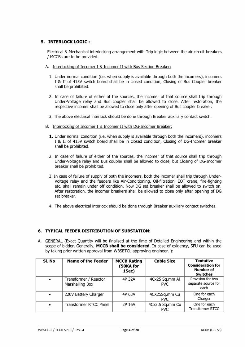
5. INTERLOCK LOGIC :
Electrical & Mechanical interlocking arrangement with Trip logic between the air circuit breakers
/ MCCBs are to be provided.
A. Interlocking of Incomer I & Incomer II with Bus Section Breaker:
1. Under normal condition (i.e. when supply is available through both the incomers), incomers
I & II of 415V switch board shall be in closed condition, Closing of Bus Coupler breaker shall be prohibited.
2. In case of failure of either of the sources, the incomer of that source shall trip through Under-Voltage relay and Bus coupler shall be allowed to close. After restoration, the
respective incomer shall be allowed to close only after opening of Bus coupler breaker.
3. The above electrical interlock should be done through Breaker auxiliary contact switch.
B. Interlocking of Incomer I & Incomer II with DG-Incomer Breaker:
1. Under normal condition (i.e. when supply is available through both the incomers), incomers
I & II of 415V switch board shall be in closed condition, Closing of DG-Incomer breaker shall be prohibited.
2. In case of failure of either of the sources, the incomer of that source shall trip through Under-Voltage relay and Bus coupler shall be allowed to close, but Closing of DG-Incomer
breaker shall be prohibited.
3. In case of failure of supply of both the incomers, both the incomer shall trip through Under-
Voltage relay and the feeders like Air-Conditioning, Oil-filtration, EOT crane, fire-fighting etc. shall remain under off condition. Now DG set breaker shall be allowed to switch on.
After restoration, the incomer breakers shall be allowed to close only after opening of DG set breaker.
4. The above electrical interlock should be done through Breaker auxiliary contact switches.
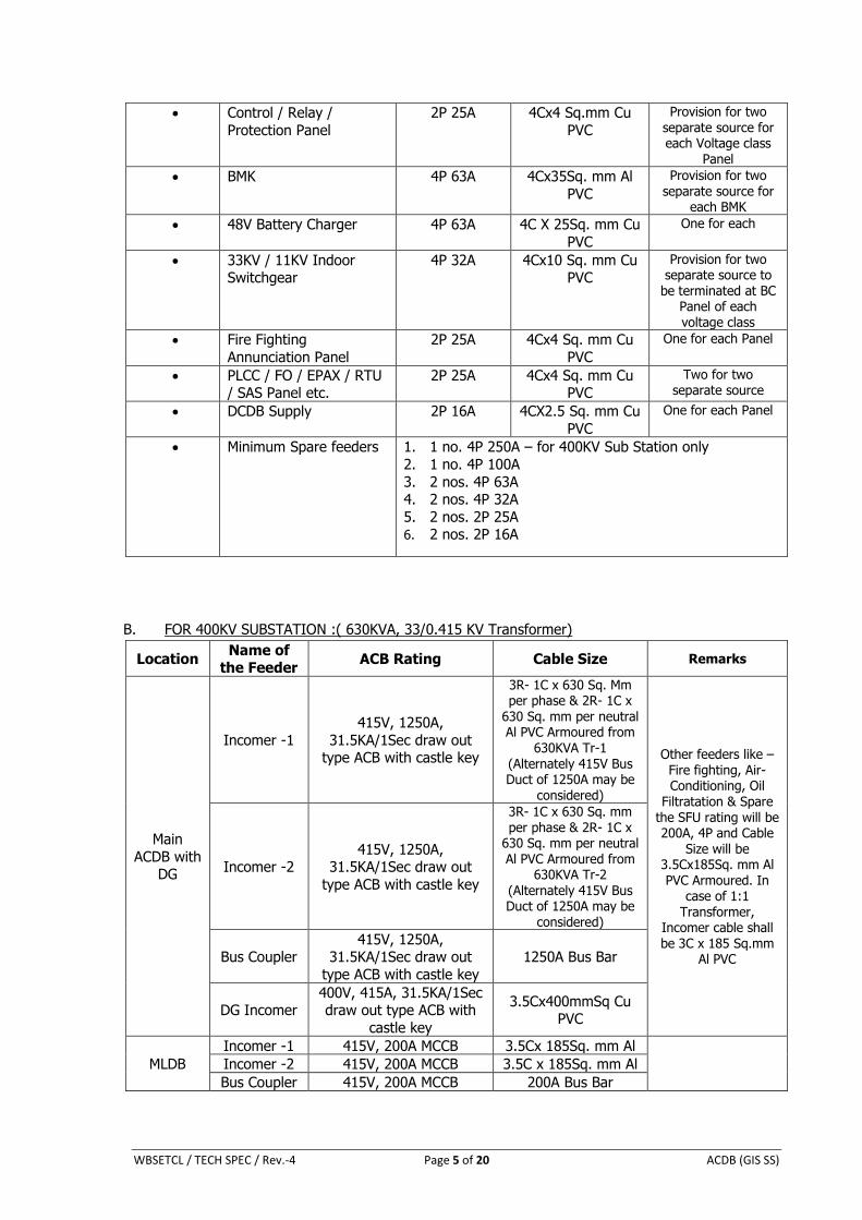
6. TYPICAL FEEDER DISTRIBUTION OF SUBSTATION:
A. GENERAL (Exact Quantity will be finalised at the time of Detailed Engineering and within the scope of bidder. Generally, MCCB shall be considered. In case of exigency, SFU can be used
by taking prior written approval from WBSETCL approving engineer. ):
Sl. No Name of the Feeder
MCCB Rating
(50KA for 1Sec)
Cable Size Tentative Consideration for
Number of Switches
Transformer / Reactor
Marshalling Box
4P 32A
4Cx25 Sq.mm Al
PVC
Provision for two separate source for
each
220V Battery Charger 4P 63A 4CX25Sq.mm Cu
PVC
One for each Charger
Transformer RTCC Panel 2P 16A 4Cx2.5 Sq.mm Cu PVC
One for each Transformer RTCC
WBSETCL / TECH SPEC / Rev.-4 Page 5 of 20 ACDB (GIS SS)
Control / Relay /
Protection Panel
2P 25A 4Cx4 Sq.mm Cu
PVC
Provision for two
separate source for each Voltage class
Panel
BMK 4P 63A 4Cx35Sq. mm Al
PVC
Provision for two separate source for
each BMK
48V Battery Charger 4P 63A 4C X 25Sq. mm Cu
PVC
One for each
33KV / 11KV Indoor Switchgear
4P 32A 4Cx10 Sq. mm Cu PVC
Provision for two separate source to
be terminated at BC Panel of each voltage class
Fire Fighting
Annunciation Panel
2P 25A 4Cx4 Sq. mm Cu
PVC
One for each Panel
PLCC / FO / EPAX / RTU / SAS Panel etc.
2P 25A 4Cx4 Sq. mm Cu PVC
Two for two separate source
DCDB Supply 2P 16A 4CX2.5 Sq. mm Cu
PVC
One for each Panel
Minimum Spare feeders 1. 1 no. 4P 250A – for 400KV Sub Station only
2. 1 no. 4P 100A
3. 2 nos. 4P 63A 4. 2 nos. 4P 32A
5. 2 nos. 2P 25A 6. 2 nos. 2P 16A
B. FOR 400KV SUBSTATION :( 630KVA, 33/0.415 KV Transformer)
Location Name of
the Feeder ACB Rating Cable Size Remarks
Main
ACDB with DG
Incomer -1
415V, 1250A,
31.5KA/1Sec draw out type ACB with castle key
3R- 1C x 630 Sq. Mm per phase & 2R- 1C x
630 Sq. mm per neutral Al PVC Armoured from
630KVA Tr-1 (Alternately 415V Bus Duct of 1250A may be
considered)
Other feeders like – Fire fighting, Air-Conditioning, Oil
Filtratation & Spare the SFU rating will be 200A, 4P and Cable
Size will be 3.5Cx185Sq. mm Al PVC Armoured. In
case of 1:1 Transformer,
Incomer cable shall be 3C x 185 Sq.mm
Al PVC
Incomer -2 415V, 1250A,
31.5KA/1Sec draw out
type ACB with castle key
3R- 1C x 630 Sq. mm per phase & 2R- 1C x
630 Sq. mm per neutral Al PVC Armoured from
630KVA Tr-2
(Alternately 415V Bus Duct of 1250A may be
considered)
Bus Coupler 415V, 1250A,
31.5KA/1Sec draw out
type ACB with castle key
1250A Bus Bar
DG Incomer 400V, 415A, 31.5KA/1Sec draw out type ACB with
castle key
3.5Cx400mmSq Cu PVC
MLDB
Incomer -1 415V, 200A MCCB 3.5Cx 185Sq. mm Al
Incomer -2 415V, 200A MCCB 3.5C x 185Sq. mm Al
Bus Coupler 415V, 200A MCCB 200A Bus Bar
WBSETCL / TECH SPEC / Rev.-4 Page 6 of 20 ACDB (GIS SS)
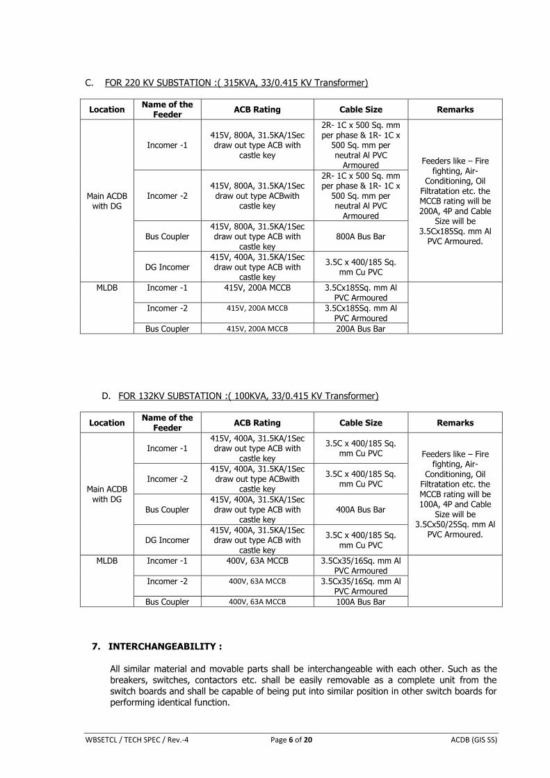
C. FOR 220 KV SUBSTATION :( 315KVA, 33/0.415 KV Transformer)
Location Name of the
Feeder ACB Rating Cable Size Remarks
Main ACDB with DG
Incomer -1 415V, 800A, 31.5KA/1Sec draw out type ACB with
castle key
2R- 1C x 500 Sq. mm per phase & 1R- 1C x
500 Sq. mm per neutral Al PVC
Armoured Feeders like – Fire
fighting, Air-Conditioning, Oil
Filtratation etc. the MCCB rating will be 200A, 4P and Cable
Size will be 3.5Cx185Sq. mm Al
PVC Armoured.
Incomer -2 415V, 800A, 31.5KA/1Sec draw out type ACBwith
castle key
2R- 1C x 500 Sq. mm per phase & 1R- 1C x
500 Sq. mm per neutral Al PVC
Armoured
Bus Coupler 415V, 800A, 31.5KA/1Sec draw out type ACB with
castle key
800A Bus Bar
DG Incomer 415V, 400A, 31.5KA/1Sec draw out type ACB with
castle key
3.5C x 400/185 Sq. mm Cu PVC
MLDB Incomer -1 415V, 200A MCCB 3.5Cx185Sq. mm Al PVC Armoured
Incomer -2 415V, 200A MCCB 3.5Cx185Sq. mm Al PVC Armoured
Bus Coupler 415V, 200A MCCB 200A Bus Bar
D. FOR 132KV SUBSTATION :( 100KVA, 33/0.415 KV Transformer)
Location Name of the
Feeder ACB Rating Cable Size Remarks
Main ACDB with DG
Incomer -1 415V, 400A, 31.5KA/1Sec draw out type ACB with
castle key
3.5C x 400/185 Sq. mm Cu PVC Feeders like – Fire
fighting, Air-Conditioning, Oil
Filtratation etc. the MCCB rating will be 100A, 4P and Cable
Size will be 3.5Cx50/25Sq. mm Al
PVC Armoured.
Incomer -2 415V, 400A, 31.5KA/1Sec draw out type ACBwith
castle key
3.5C x 400/185 Sq. mm Cu PVC
Bus Coupler 415V, 400A, 31.5KA/1Sec draw out type ACB with
castle key 400A Bus Bar
DG Incomer 415V, 400A, 31.5KA/1Sec draw out type ACB with
castle key
3.5C x 400/185 Sq. mm Cu PVC
MLDB Incomer -1 400V, 63A MCCB 3.5Cx35/16Sq. mm Al PVC Armoured
Incomer -2 400V, 63A MCCB 3.5Cx35/16Sq. mm Al PVC Armoured
Bus Coupler 400V, 63A MCCB 100A Bus Bar
7. INTERCHANGEABILITY :
All similar material and movable parts shall be interchangeable with each other. Such as the breakers, switches, contactors etc. shall be easily removable as a complete unit from the
switch boards and shall be capable of being put into similar position in other switch boards for performing identical function.
WBSETCL / TECH SPEC / Rev.-4 Page 7 of 20 ACDB (GIS SS)
8. CONSTRUCTION :
The switch boards shall be of multi-cubicle or multi box factory-built air-insulated type, fully
enclosed with doors for access to the interior. 3.00 mm. thick steel sheet shall be used for the
fabrication of the panels. However 2mm thick cold rolled sheet steel with powder coating is also acceptable. Boards shall be easily extendible on both sides, by the addition of the vertical
section after removing the end covers.
The complete panels shall not be more than 2450 mm. high with the channel base and the depth shall be preferably within 1000 mm. wide measured from rear to front faces. The
working height shall be minimum 450 mm. to maximum 2000 mm. The width of the panel will
depend upon the no. of circuits to be accommodated. Board shall be easily extendible on both sides, by the addition of the vertical sections after removing the end covers.
All boards shall be divided into distinct vertical sections each comprising of :
(i) A completely enclosed bus bar compartment for running horizontal and vertical
Aluminium bus bars. Bus bar chamber shall be completely enclosed with metallic portions. Bolted covers shall be provided for access to horizontal and vertical bus bars
and all joints for repair and maintenance, which shall be feasible without disturbing feeder compartment. Proper ventilation arrangement shall have to be arranged and that
shall be decided by the purchaser at the time of approval of drawings (ii) Completely enclosed switchgear compartments one for each circuit for housing circuit
breaker or MCCB or motor starter.
(iii) A compartment for power and control cable. Door of compartment shall be hinged. Cable compartment shall have no communication with bus bar chamber.
(iv) A compartment for relays and other control devices associated with a circuit breaker. (v) The panels shall be designed to facilitate cable entry from the bottom through entry
holes of removable gland plates provided at the bottom of the cubicle. All the
accessories required for terminations of cables in the ACDB such as cable gland, terminal block etc. shall be within the scope of supply.
After isolation of power and control circuit connections it shall be possible to safely carry out maintenance in a compartment with the bus bar and adjacent circuit live. Necessary shrouding
arrangement shall be provided over the cable terminations located in cable alley.
Where two incomer air circuit breakers are provided in the same vertical section, insulating
barriers and shroud shall be provided in the rear cable compartment in order to avoid accidental touch with live parts of one circuit when working on the other circuit.
The connections from bus bars to main switch shall be fully insulated/shrouded and securely
bolted. The partition between the feeder compartment and cable alley may be non-metallic
and shall allow cables cores with lugs to be easily inserted in the feeder compartment for termination.
The switch board shall be vermin proof and suitable for use in tropical climate. All ventilating
louvers and holes shall be covered with fine wire mesh from inside. Necessary pre-treatment
of the panel surface is to be done by seven tank process followed by epoxy powder coated paint. The colour of the exterior of the panel shall be of same colour as that of the main
control and relay panel. The colour of the interior panel should be as to provide a colour contrasting background for the wiring inside the cubicle.
The switchboards shall be mounted on channel and shall be complete with channel bottom
plates made of structural steel, grouting bolts, earthing bolts, washers, cable glands etc.
Both the single and three phase switches as well as the fuse terminals provided on the panel
shall be of best quality and easy in operation.
WBSETCL / TECH SPEC / Rev.-4 Page 8 of 20 ACDB (GIS SS)
The tentative entries of power and control cable shall be from bottom.
Adapter panels and dummy panels required to meet the various bus bar arrangements and layout required shall be included in Bidder’s scope of works.
All modules shall be fixed type except air circuit breaker module which shall be draw out type.
All disconnecting contacts for power circuits shall be of robust design and fully self-aligning. Fixed and moving contacts of the power draw out contact system shall be silver-plated and
both fixed and moving contacts shall be replaceable.
All Distribution Boards shall be single front type.
All single front board shall be provided with removable bolted covers at the rear. The covers
shall be provided with danger levels.
Sheet steel barriers shall be provided between two adjacent panels running to the full height
of the switch board, except for the horizontal bus bar compartment.
A. POWER BUS BARS AND INSULATORS
Bus bars shall be of Aluminium alloy (current density should be less than 0.75 A / sq.
mm), liberally sized for the specified continuous current rating as per approved scheme and short circuit current rating of 50 KA (rms) for 3 sec. Necessary precaution shall be taken to
avoid bimetallic action. Means shall be provided for identifying various phases of bus bars by red, yellow and blue paint. The cross section of the bus bars shall be uniform through out the
length of switch gear.
Bus support shall be of arc resistant, non-tracking, low absorption type installations of high
impact strength to withstand normal as well as fault condition stresses.
i. EARTH BUS : A galvanised steel earthing shall be provided at the bottom of each panel and shall extend through out the length of switchboard. It shall be welded/bolted to the
frame work of each panel and breaker earthing contact bar. Vertical bus shall be provided in each vertical section which shall in turn be bolted/welded to main horizontal
ground bus.
ii. The earth bus shall have sufficient cross section to carry momentary short circuit and
short time fault currents to earth bus without exceeding the allowable temperature rise.
iii. The horizontal earth bus shall be projected out of the switch board ends and shall have
pre-drilled holes for bolted connection between this bus to sub-station earthing conductor. A joint spaced and taps to earth bus shall be made through at least two bolts.
iv. All non-current metal works of the switch board shall be effectively bonded to the earth
bus.
B. AIR CIRCUIT BREAKERS :
Incoming and Bus sectionalise air circuit breaker shall be four pole air break horizontal draw
out type and shall have inherent fault making and breaking capacities as per requirement. All
the poles of circuit breakers shall open and close simultaneously. The neutral pole shall be 100% rated. Provision of remote electrical operation of the breakers shall be there.
WBSETCL / TECH SPEC / Rev.-4 Page 9 of 20 ACDB (GIS SS)
Circuit breakers shall be mounted along with it operating mechanism on a wheeled carriage. Suitable guides shall be provided to minimise misalignment of the breaker.
There shall be ‘Service’, ‘Test’ ‘ISOLATED’ and ‘MAINTENANCE’ positions for the breakers. In
‘Test’ position the circuit breaker shall be capable of being tested for operation without
energising the power circuits i.e. the power Contacts shall be disconnected while the Control circuits shall remain undisturbed. Locking facilities shall be provided so as to prevent
movement of the circuit breaker from the ‘SERVICE’, ‘TEST’. It shall be possible to close the door in ‘TEST’ position.
There should be provision for locking the air circuit breaker in ‘ISOLATED’ position to achieve
mechanical interlocking with Incomer & Bus sectionalizer Air Circuit Breakers.
All circuit breakers shall be provided with 4 NO and 4 NC potentially free auxiliary contacts.
These contacts shall be in addition to those required for internal mechanism of the breaker. Separate limit switches each having required number of contacts shall be provided in both
‘SERVICE’ & ‘TEST’ position of the breaker. All contacts shall be rated for making continuously
carrying and breaking 10 Amps. At 230 V AC and 1 Amp.(Inductive) at 220 V DC.
Suitable mechanical indications shall be provided on all circuit breakers to show ‘OPEN’, ‘CLOSE’, ’SERVICE’, ‘TEST’ and ‘SPRING CHARGED’ positions.
Movement of a circuit breaker between SERVICE AND TEST positions shall not be possible
unless it is in OPEN position. Racking interlock for this shall be provided.
Closing of a circuit breaker shall not be possible unless it is in SERVICE, TEST POSITION or in
FULLY WITHDRAWN POSITION.
Circuit breaker cubicles shall be provided with safety shutters operated automatically by the
movement of the circuit breaker carriage to cover the stationary isolated contacts when the breaker is withdrawn. It shall however, be possible to open the shutters intentionally, against
spring pressure for testing purpose.
A breaker of particular rating shall be prevented from insertion in a cubicle of a different
rating. The ACB’s shall have rating error preventor to achieve this.
Circuit breakers shall be provided with electrical anti-pumping and trip free feature even if mechanical anti-pumping feature is provided.
Mechanical tripping shall be possible by means of front mounted RED ‘Trip’ push-button. In
case of electrically operated breakers these push-buttons shall be shrouded to prevent
accidental operation.
Power operated mechanism shall be provided with a universal motor suitable for operation 220V DC Control supply with voltage variation from 85% to 110% rated voltage. Motor
insulation shall be class ‘E’ or better.
Once the closing springs are discharged, after the one closing operation of circuit breaker, it
shall automatically initiate, recharging of the spring. The motor shall be such that it requires not more than 30 seconds for fully charging the closing spring.
The mechanism shall be such that as long as power is available to the motor, a continuous
sequence of closing and opening operations shall be possible. After failure of power supply at
least one open-close-open operation shall be possible.
WBSETCL / TECH SPEC / Rev.-4 Page 10 of 20 ACDB (GIS SS)
Provision shall be made for emergency manual charging and as soon as this manual charging
handle is coupled, the motor shall automatically get mechanically decoupled.
All circuit breakers shall be provided with closing and trip coils. The closing coils shall operate correctly at all values of Voltage between 85% to 110% at rated control voltage. The trip coil
shall operate satisfactorily under all values of supply voltage between 70% to 110% of rated
control voltage Trip ckt supervision shall be provided..
The door of the circuit breaker compartment shall be interlocked so that (1) door cannot be opened while the breaker is in closed position and (2) when the door is open the breaker
cannot be closed. However, facility to defeat this interlock shall be provided for testing purpose.
Provision for mechanical closing of the breaker only in ‘TEST’ and ‘WITHDRAWN’ positions shall be made.
Air Circuit Breakers shall be from one of the following manufacturer’s complying with technical
specification & relevant IS & IEC
a) M/s Siemens b) M/s L & T
c) M/s ABB d) M/s Schneider
e) M/s GE f) M/s Havells
C. SWITCH FUSE UNIT (SFU), MOULDED CASE CIRCUIT BREAKER (MCCB) AND (MCB)
SFU / MCCB shall be 4 pole /2 pole, capable of safely breaking the fault current of the
associated feeder. Rating of SFU / MCCB’s shall be chosen by the contractor depending upon
requirement of outgoing feeders as stipulated in this technical specification and shall be subject to approval of WBSETCL.
All the SFU / MCCB shall be flush mounted on AC Distribution boards provided with Rotary
operating handle with clear ON-OFF trip indication.
MCCBs shall be provided with thermo-magnetic type release for over current and short circuit
protection. The o/c setting shall be adjustable type. The s/c settings shall be adjustable type.
The setting range of thermal release and breaking capacity of MCCBs are to be specified and shall conform to system requirement. MCCB Knob shall indicate the true position of the
equipment. MCCBs shall conform to relevant Indian Standard IS : 13947 Part 2 and shall be of
P2 duty.
For tripping of any of the outgoing feeder, visual and audible alarm arrangement shall be provided in the AC Board. However arrangement has to be made for getting audible alarm at
the control room for the knowledge of the operator regarding tripping of the outgoing feeders.
Necessary arrangement shall also be provided for acceptance and resetting of the audible alarm. In case of tripping of Incoming feeder breaker or Bus sectionalising breaker,
arrangement of both audible and visual annunciation shall be made both at AC Board as well in Control room. Acceptance and resetting arrangement is to be provided.
Interlocks shall be provided such that it is possible to open the cubicle door only when the
SFU / MCCB is in ‘OFF’ position and to close the SFU / MCCB when the door is closed.
Miniature Circuit Breaker (MCB) shall conform to IEC:898-1987 and IS:8828.
WBSETCL / TECH SPEC / Rev.-4 Page 11 of 20 ACDB (GIS SS)
SFU, MCCB & MCB shall be from one of the following manufacturer’s complying with technical
specification & relevant IS & IEC
a) M/s Siemens
b) M/s L & T c) M/s ABB
d) M/s Schneider
e) M/s GE f) M/s Havells
D. CONTROL AND SELECTOR SWITCHES :
a) Control and Selector switches shall be rotary type with escutcheon plates clearly marked
to show the junction and positions. Switches shall be of sturdy construction suitable for making on panel front.
b) Voltmeter selector switches shall have four stay put position with adequate no. of contacts for 3-phase 4-wire system. These shall be oval handles. .
c) Contacts of the switches shall be spring assisted and shall be of suitable material for
giving long trouble free services.
d) Contact ratings shall be at least the followings :
(i) Make and carry continuously : 10 Amp.
(ii) Breaking current at 230 V AC : 5 Amp. (at 0.3 p.f. lagging)
E. AIR BREAK SWITCHES :
a) Air breaker switch shall be of heavy duty, single throw group operated, load break, fault
make type complying IS:4046.
b) Switch operating handles shall be provided with pad locking facilities to lock them in ‘OFF’
position.
c) All switches shall be adequately rated so as to be fully protected by the associated fuses during all abnormal conditions such as over load, locked motor, short circuit etc.
d) Interlock shall be provided so that cubicle door can only be opened when the switch is in ‘OFF’ position and to close the switch only when the door is closed. However, suitable
means shall also be provided to intentionally defeat the interlocks as mentioned above.
e) Switches and fuses MCCB/MCB for AC control supply and heater supply wherever required shall be mounted inside the cubicles.
F. INDICATING LAMPS OF CONTROL SWITCHES :
Indicating lamps shall be of the panel mounting cluster LED type. The lamps shall have
suitable size plates marked with its function, wherever necessary. Lamps shall have translucent lamp covers of the following colours.
RED : Breaker Closed.
GREEN : Breaker Open
WHITE : Breaker Auto-Trip
BLUE : For all healthy condition. (e.g. Control supply and also for
WBSETCL / TECH SPEC / Rev.-4 Page 12 of 20 ACDB (GIS SS)
“SPRING CHARGED” and “TRIP CIRCUIT HEALTHY”)
AMBER : For all alarm conditions (e.g. overload). Also for ‘SERVICE’ and ‘TEST’ positions indicators.
G. SPACE HEATERS :
Space heaters shall be provided for preventing harmful moisture condensation in all the AC
Boards. The space heaters shall be suitable for continuous operation on 230 V AC, 50 HZ, 1-phase supply and shall be automatically controlled by thermostats. Necessary isolating
switches and fuses shall also be provided.
H. INTERNAL WIRING AND TERMINAL BLOCK :
(a) All switch boards shall be supplied completely wired internally upto the terminal blocks.
(b) All inter cubicle and inter panel wiring and connections between panel of same switch board including all bus wiring for AC and DC supplies shall be provided by the contractor.
(c) All internal wiring shall be carried out with PVC insulated, stranded copper conductor, single core, 2.5 sq. mm. or larger stranded copper wires. CT Ckts. shall be wired with 4
sq. mm. voltage grade and insulation of copper wires shall be same as above. Voltage
drop shall be allowed only in the tune of 5% at the remote end of the longest outgoing feeder from the AC Panel board and 15% drop in case of starting of motor of the remote
end.
(d) All wiring shall be properly supported, neatly bunched, readily accessible and securely
connected to equipment terminals and terminal blocks.
(e) Each wire shall be identified at both ends and shall be properly tagged and ferruled in
compliance with approved drawings. Wires shall not be spliced or tapped between
terminal points.
(f) Terminal blocks shall be of 1100 V grade ‘Elmex/connect well’ make and have continuous
rating to carry the maximum expected current on the terminals. The terminal blocks shall be fully enclosed with removable covers of transparent, non-deteriorating type plastic
material. Insulating barrier shall be provided between the terminal. The terminal blocks
shall have locking arrangement to prevent its escape from the rails. 20% spare terminals are to be provided. These spare terminals shall be uniformly distributed on all terminal
blocks.
(g) Terminal blocks for CT secondary leads shall be provided with test links and isolating
facilities. CT secondary leads shall be provided with short circuiting and earthing facilities.
Jam nut should be provided with shorting link.
(h) All terminal blocks shall be normally suitable for terminating on each side, two (2) nos. of
2.5 mm. sq. size stranded copper conductor. However, terminal blocks to be used in conjunctive with CT shall be suitable for terminating 4 sq. mm. single core Copper wires.
(i) All terminals shall be numbered for identification and grouped according to the function. Engraved white on-black labels shall be provided on the terminal blocks.
(j) Terminal blocks shall be arranged with at least 100 mm. clearance between two sets of
terminal block. The minimum clearance between the first row of terminal block and the associated cable gland plate shall be 250 mm.
I. POWER CABLE TERMINATIONS :
(a) Cable termination compartment and arrangement for power cables shall be suitable for
stranded Aluminium Conductor, armoured PVC insulated and sheathed 4 / 3.5 -core, 1100V grade.
WBSETCL / TECH SPEC / Rev.-4 Page 13 of 20 ACDB (GIS SS)
(b) All necessary cable terminating accessories such as Gland plates, supporting clamps and
brackets, power cable lugs, hardware etc. shall be provided by the contractor to suit the final cable sizes.
(c) The gland plate shall be of removable type and shall cover the entire cable alley. Bidder shall also ensure that sufficient space is provided for all cable termination.
J. GROUNDING :
An Aluminium strip ground bus rated to carry maximum fault current for the specified
duration shall be provided along the entire length of the distribution board.
Each casing of the equipments, relays, instruments provided in the board shall be connected
directly to the ground bus by independent stranded copper wires of not less than 2.5 sq. mm.
The earth bus shall have sufficient cross-section to carry the momentary short circuit and short time fault currents to earth without exceeding the allowable temperature rise. The
ground bus shall be brought out to two terminals at the two ends of the switch board for Connecting G.S. Flat of 50×10mm for all voltage classes. CT & PT secondary neutral point
shall be at one place only on the terminal block. Such earthing shall be made through links.
K. TROPICAL FINISH :
All electrical equipment, accessories and insulation of wiring shall have fungus protection involving special treatment on insulation and metal against fungus, insect and corrosion.
L. INSULATION :
The insulation at any point in the distribution board shall be of 1.1 KV grade.
9. ASSOCIATED EQUIPMNET AND ACCESSORIES:
A. CABLE GLANDS :
All feeders shall be provided with suitable dust tight screwed brass cable glands conforming to
the relevant IS standard.
Gland shall project above the gland plate. Terminating cables shall be armoured and the
armour rods shall be connected to earth bar.
B. METERS :
The accuracy class of Electronic type KWH meter shall be 0.5. One KWH meter of 3-phase, 4-wire type shall be flush mounted on each of the incoming breaker compartments, Ammeter
and voltmeter shall be of 72* 144 sq.mm and of flush mounting digital type with accuracy
+/- 1% of full scale. The meters shall conform to the appropriate IS specification. All circuits of the meters shall be capable of withstanding 20% overload for a period of at least 8 hours.
Three no. digital Ammeter and one no digital Voltmeter shall be provided for each incoming CB’s with voltmeter selector switch.
WBSETCL / TECH SPEC / Rev.-4 Page 14 of 20 ACDB (GIS SS)
C. NUMERICAL RELAYS :
All the protections shall be of numerical type (shall be as per make list) and supported by Test
Certificates from Govt. recognized Test house and performance certificates from Govt./Power Utilities.
The relay shall have –
a) Minimum two characteristics, one IDMT of 3 sec. and the other one of definite time characteristic and the same should be site selectable.
b) Wide range of time and current setting in very small steps without sacrificing the relay characteristics.
c) Tripping indication for different type of faults until reset by the operator. d) Continuous self supervision along with self diagnostic feature for faults within the relay
and the relay should have potential free ‘Change over Contact’ for annunciation in the event
of internal failure. e) Output contacts having sufficient current rating to directly energise trip coil of circuit
breaker. f) LED indication facility for visual annunciation of different type of faults including phase
identification.
g) Individually site selectable binary Output and Input and latching option for binary Output.
Motor starters shall be provided with ambient temp. compensated, time lagged, hand reset type over load relays with adjustable settings ranges to suit motor ratings. These relays shall
have separate black coloured hand reset push button mounted on compartment door and shall have at least one changeover contact.
D. INSTRUMENT TRANSFORMER :
All current transformers shall be completely encapsulated cast resin insulated wound type suitable for continuous operation at the temperature prevailing inside the switch gear
enclosures, when the switch board is operating at its rated condition and the outside ambient temperature is 50oC.
All instrument transformers shall be able to withstand the thermal and mechanical stresses resulting from the maximum short circuit.
All instrument transformers shall have clear indelible polarity markings.
Accuracy class of current transformer shall be of 5P and 1 for protection and metering. The
insulation level of the CT shall be suitable for 1.1KV grade service. The CT ratio associated
with 630 KVA Station Service Transformer shall be 1250/1A, for 315KVA station service transformer shall be 800/1A and that of 100KVA shall be 200/1.
10. NAMEPLATES AND LABELS :
ACDB shall be provided with prominent, engraved identification plates. The module identification plate shall clearly give feeder number and feeder designation. For single front
switchboards, similar panel and board identification labels shall be provided at the rear also.
All name plates shall be non-rusting metal or 3-ply lamicold with white engraved lettering on
black base ground. Suitable plastic sticker labels shall be provided for easy identification of all equipments, located inside the panel / module. These labels shall be positioned so as to be
clearly visible and shall give device number as mentioned in the module wiring drawings.
WBSETCL / TECH SPEC / Rev.-4 Page 15 of 20 ACDB (GIS SS)
11. PAINTING
The Panels shall be pre-treated using 7-Tank process and then Epoxy Powder Coated with Paint shade of RAL 7032.
12. PACKING AND DESPATCH :
All equipments shall have to be dispatched suitably and securely packed in wooden crates, suitable for handling during transit by rail and / or road.
13. CONTRACT DRAWING & CATALOGUE :
A. After placement of Letter of Award six (6) copies of following drawings, GTP and literature shall be submitted for approval :
i) Single line diagram of each AC Board.
ii) General Arrangement drawing showing dimensions of front and rear view of each
switch board with relay instruments and other devices position marked. Height, width,
depth and ground fixing arrangement shall have to be indicated.
iii) Schematic wiring diagram for each switch board.
iv) Catalogue on each type of circuit breaker, MCCB, switches, fuse, relays, meters etc. offered. The list of drawing shall be furnished in the schedule attached herein.
B. After completion of the work, four (04) sets of as-built drawings and maintenance manual/catalogue of all equipment both in hard & soft format shall be submitted for
our record and distribution to site.
14. TESTS AT MANUFACTURER’S WORKS AND TEST CERTIFICATES :
A. Acceptance and routine test at manufacturer’s works shall be carried out on each AC Board as per stipulation of relevant Indian Standard. The entire cost of acceptance and routine
tests are to be carried out shall be treated as included in the quoted price of all Distribution Board.
All the acceptance and routine tests shall be carried out in presence of representative of WBSETCL. Three (3) copies of test reports both in hard & soft format shall be
submitted to this end for approval and distribution to site.
B. The Contractor shall give at least 15 (fifteen) days advance notice intimating the actual
date of inspection and details of all tests that are to be carried out.
15. GUARANTEE :
Electrical characteristic shall be guaranteed by the bidder. In case of failure of materials to
meet the guarantee, WBSETCL shall have right to reject the material. Guaranteed Technical Particulars in prescribed format are to be submitted by successful bidder during detailed
engineering along with submitted drawings/documents.
WBSETCL / TECH SPEC / Rev.-4 Page 16 of 20 ACDB (GIS SS)
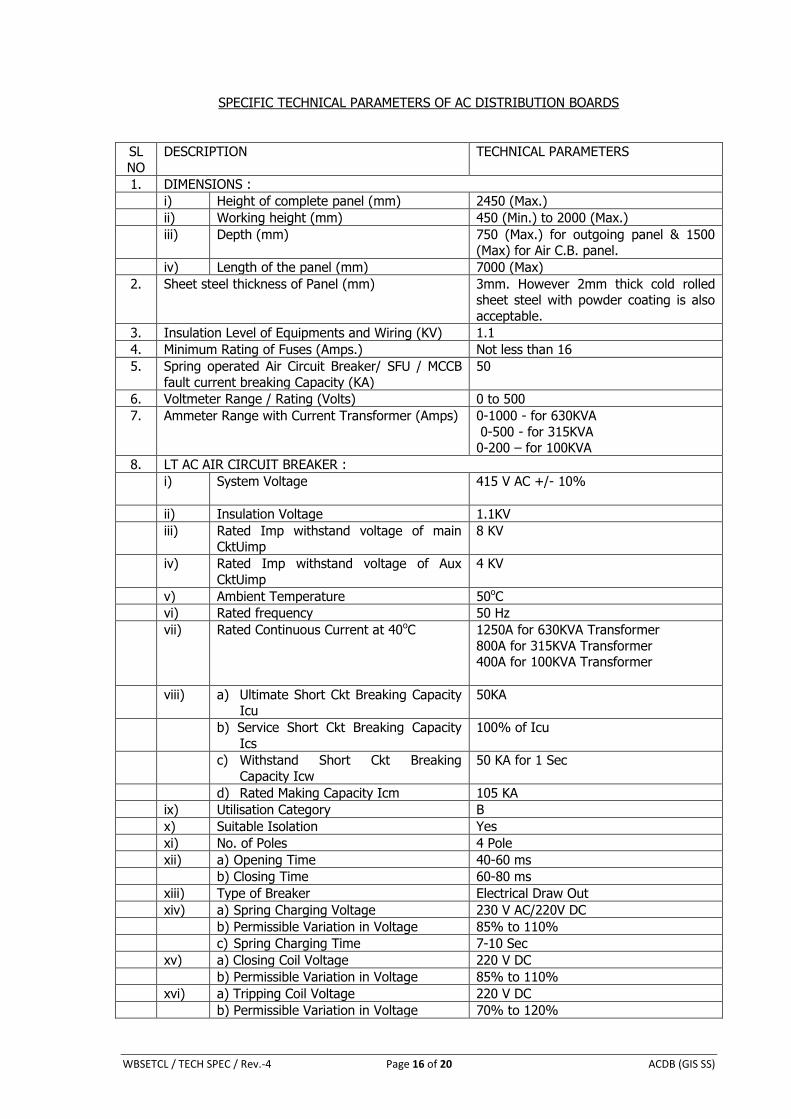
SPECIFIC TECHNICAL PARAMETERS OF AC DISTRIBUTION BOARDS
SL
NO
DESCRIPTION TECHNICAL PARAMETERS
1. DIMENSIONS :
i) Height of complete panel (mm) 2450 (Max.)
ii) Working height (mm) 450 (Min.) to 2000 (Max.)
iii) Depth (mm) 750 (Max.) for outgoing panel & 1500 (Max) for Air C.B. panel.
iv) Length of the panel (mm) 7000 (Max)
2. Sheet steel thickness of Panel (mm) 3mm. However 2mm thick cold rolled sheet steel with powder coating is also
acceptable.
3. Insulation Level of Equipments and Wiring (KV) 1.1
4. Minimum Rating of Fuses (Amps.) Not less than 16
5. Spring operated Air Circuit Breaker/ SFU / MCCB
fault current breaking Capacity (KA)
50
6. Voltmeter Range / Rating (Volts) 0 to 500
7. Ammeter Range with Current Transformer (Amps) 0-1000 - for 630KVA
0-500 - for 315KVA 0-200 – for 100KVA
8. LT AC AIR CIRCUIT BREAKER :
i) System Voltage 415 V AC +/- 10%
ii) Insulation Voltage 1.1KV
iii) Rated Imp withstand voltage of main CktUimp
8 KV
iv) Rated Imp withstand voltage of Aux
CktUimp
4 KV
v) Ambient Temperature 50oC
vi) Rated frequency 50 Hz
vii) Rated Continuous Current at 40oC 1250A for 630KVA Transformer
800A for 315KVA Transformer 400A for 100KVA Transformer
viii) a) Ultimate Short Ckt Breaking Capacity Icu
50KA
b) Service Short Ckt Breaking Capacity
Ics
100% of Icu
c) Withstand Short Ckt Breaking
Capacity Icw
50 KA for 1 Sec
d) Rated Making Capacity Icm 105 KA
ix) Utilisation Category B
x) Suitable Isolation Yes
xi) No. of Poles 4 Pole
xii) a) Opening Time 40-60 ms
b) Closing Time 60-80 ms
xiii) Type of Breaker Electrical Draw Out
xiv) a) Spring Charging Voltage 230 V AC/220V DC
b) Permissible Variation in Voltage 85% to 110%
c) Spring Charging Time 7-10 Sec
xv) a) Closing Coil Voltage 220 V DC
b) Permissible Variation in Voltage 85% to 110%
xvi) a) Tripping Coil Voltage 220 V DC
b) Permissible Variation in Voltage 70% to 120%
WBSETCL / TECH SPEC / Rev.-4 Page 17 of 20 ACDB (GIS SS)
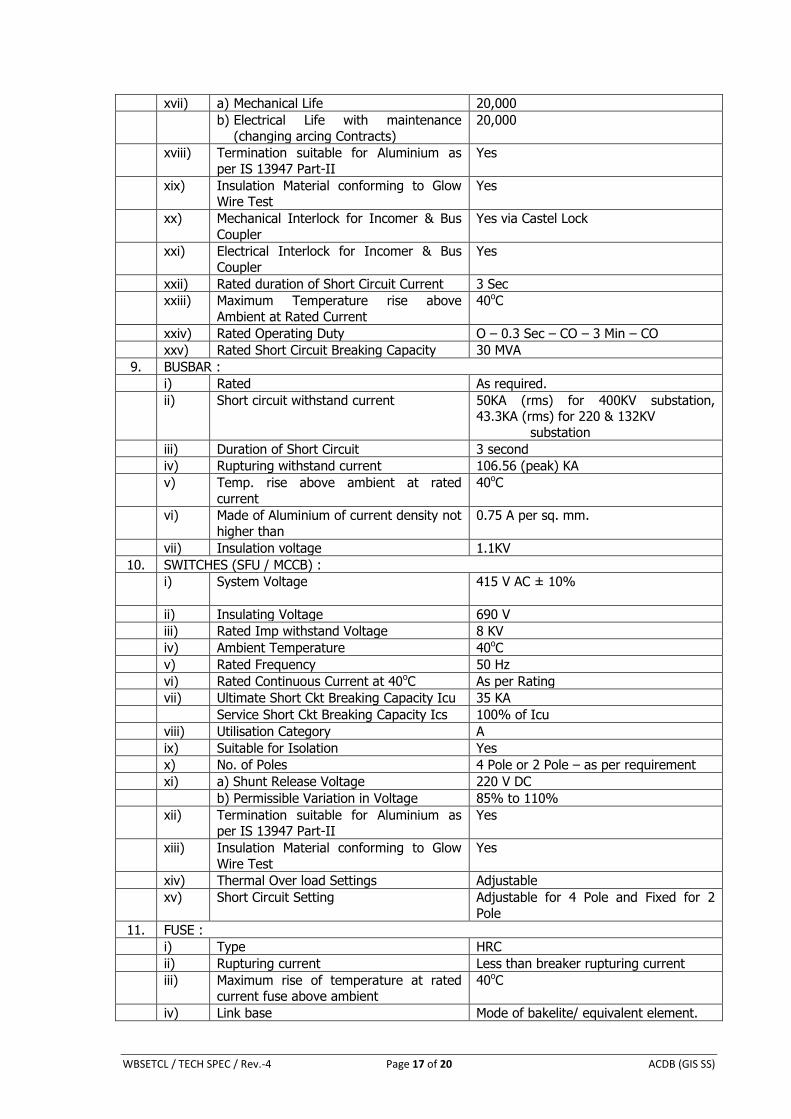
xvii) a) Mechanical Life 20,000
b) Electrical Life with maintenance
(changing arcing Contracts)
20,000
xviii) Termination suitable for Aluminium as
per IS 13947 Part-II
Yes
xix) Insulation Material conforming to Glow Wire Test
Yes
xx) Mechanical Interlock for Incomer & Bus
Coupler
Yes via Castel Lock
xxi) Electrical Interlock for Incomer & Bus
Coupler
Yes
xxii) Rated duration of Short Circuit Current 3 Sec
xxiii) Maximum Temperature rise above
Ambient at Rated Current
40oC
xxiv) Rated Operating Duty O – 0.3 Sec – CO – 3 Min – CO
xxv) Rated Short Circuit Breaking Capacity 30 MVA
9. BUSBAR :
i) Rated As required.
ii) Short circuit withstand current 50KA (rms) for 400KV substation, 43.3KA (rms) for 220 & 132KV
substation
iii) Duration of Short Circuit 3 second
iv) Rupturing withstand current 106.56 (peak) KA
v) Temp. rise above ambient at rated
current
40oC
vi) Made of Aluminium of current density not
higher than
0.75 A per sq. mm.
vii) Insulation voltage 1.1KV
10. SWITCHES (SFU / MCCB) :
i) System Voltage 415 V AC ± 10%
ii) Insulating Voltage 690 V
iii) Rated Imp withstand Voltage 8 KV
iv) Ambient Temperature 40oC
v) Rated Frequency 50 Hz
vi) Rated Continuous Current at 40oC As per Rating
vii) Ultimate Short Ckt Breaking Capacity Icu 35 KA
Service Short Ckt Breaking Capacity Ics 100% of Icu
viii) Utilisation Category A
ix) Suitable for Isolation Yes
x) No. of Poles 4 Pole or 2 Pole – as per requirement
xi) a) Shunt Release Voltage 220 V DC
b) Permissible Variation in Voltage 85% to 110%
xii) Termination suitable for Aluminium as per IS 13947 Part-II
Yes
xiii) Insulation Material conforming to Glow
Wire Test
Yes
xiv) Thermal Over load Settings Adjustable
xv) Short Circuit Setting Adjustable for 4 Pole and Fixed for 2
Pole
11. FUSE :
i) Type HRC
ii) Rupturing current Less than breaker rupturing current
iii) Maximum rise of temperature at rated current fuse above ambient
40oC
iv) Link base Mode of bakelite/ equivalent element.
WBSETCL / TECH SPEC / Rev.-4 Page 18 of 20 ACDB (GIS SS)
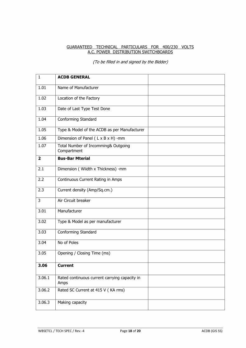
GUARANTEED TECHNICAL PARTICULARS FOR 400/230 VOLTS A.C. POWER DISTRIBUTION SWITCHBOARDS
(To be filled in and signed by the Bidder)
1 ACDB GENERAL
1.01 Name of Manufacturer
1.02 Location of the Factory
1.03 Date of Last Type Test Done
1.04 Conforming Standard
1.05 Type & Model of the ACDB as per Manufacturer
1.06 Dimension of Panel ( L x B x H) -mm
1.07 Total Number of Incomming& Outgoing
Compartment
2 Bus-Bar Mterial
2.1 Dimension ( Wiidth x Thickness) -mm
2.2 Continuous Current Rating in Amps
2.3 Current density (Amp/Sq.cm.)
3 Air Circuit breaker
3.01 Manufacturer
3.02 Type & Model as per manufacturer
3.03 Conforming Standard
3.04 No of Poles
3.05 Opening / Closing Time (ms)
3.06 Current
3.06.1 Rated continuous current carrying capacity in
Amps
3.06.2 Rated SC Current at 415 V ( KA rms)
3.06.3 Making capacity
WBSETCL / TECH SPEC / Rev.-4 Page 19 of 20 ACDB (GIS SS)
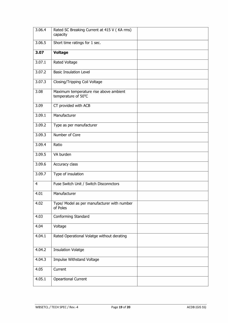
3.06.4 Rated SC Breaking Current at 415 V ( KA rms)
capacity
3.06.5 Short time ratings for 1 sec.
3.07 Voltage
3.07.1 Rated Voltage
3.07.2 Basic Insulation Level
3.07.3 Closing/Tripping Coil Voltage
3.08 Maximum temperature rise above ambient temperature of 50oC
3.09 CT provided with ACB
3.09.1 Manufacturer
3.09.2 Type as per manufacturer
3.09.3 Number of Core
3.09.4 Ratio
3.09.5 VA burden
3.09.6 Accuracy class
3.09.7 Type of insulation
4 Fuse Switch Unit / Switch Disconnctors
4.01 Manufacturer
4.02 Type/ Model as per manufacturer with number of Poles
4.03 Conforming Standard
4.04 Voltage
4.04.1 Rated Operational Volatge without derating
4.04.2 Insulation Volatge
4.04.3 Impulse Withstand Voltage
4.05 Current
4.05.1 Opeartional Current
WBSETCL / TECH SPEC / Rev.-4 Page 20 of 20 ACDB (GIS SS)
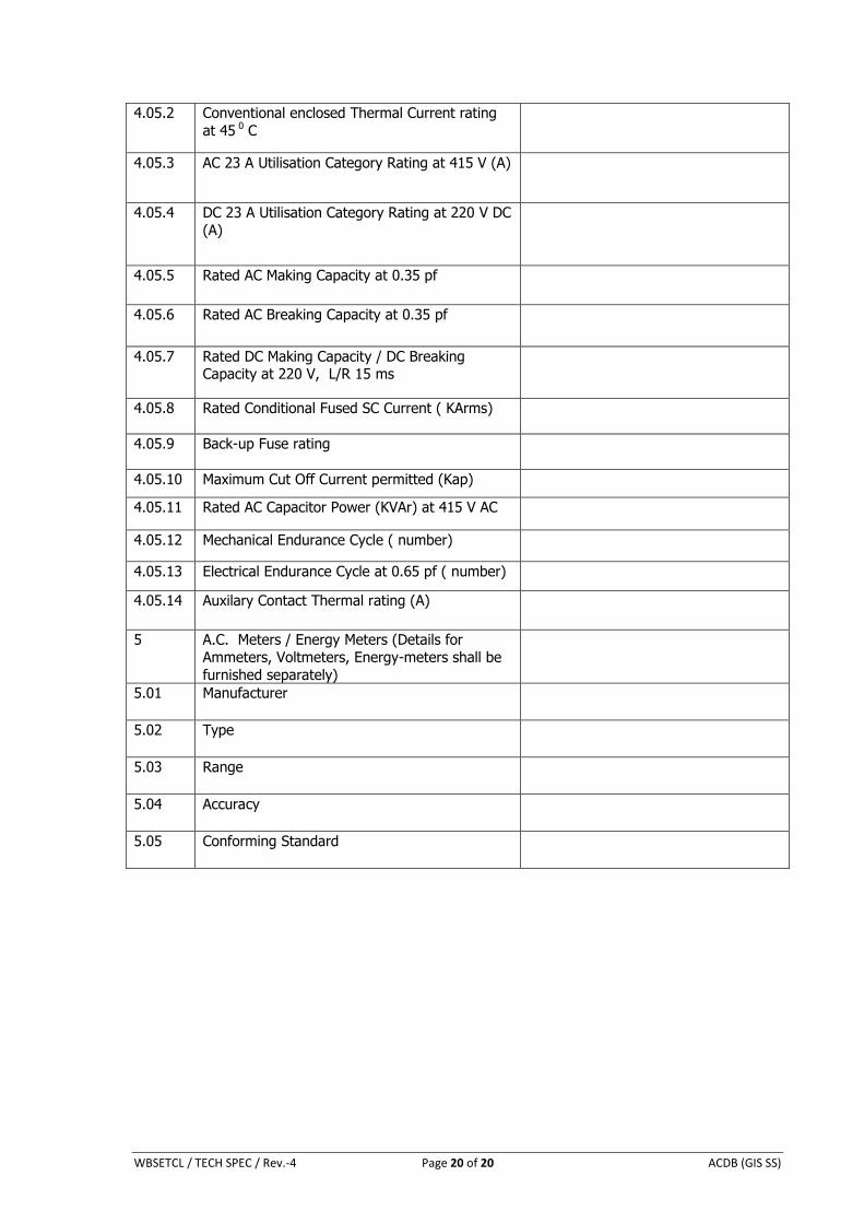
4.05.2 Conventional enclosed Thermal Current rating
at 45 0 C
4.05.3 AC 23 A Utilisation Category Rating at 415 V (A)
4.05.4 DC 23 A Utilisation Category Rating at 220 V DC
(A)
4.05.5 Rated AC Making Capacity at 0.35 pf
4.05.6 Rated AC Breaking Capacity at 0.35 pf
4.05.7 Rated DC Making Capacity / DC Breaking Capacity at 220 V, L/R 15 ms
4.05.8 Rated Conditional Fused SC Current ( KArms)
4.05.9 Back-up Fuse rating
4.05.10 Maximum Cut Off Current permitted (Kap)
4.05.11 Rated AC Capacitor Power (KVAr) at 415 V AC
4.05.12 Mechanical Endurance Cycle ( number)
4.05.13 Electrical Endurance Cycle at 0.65 pf ( number)
4.05.14 Auxilary Contact Thermal rating (A)
5 A.C. Meters / Energy Meters (Details for
Ammeters, Voltmeters, Energy-meters shall be
furnished separately)
5.01 Manufacturer
5.02 Type
5.03 Range
5.04 Accuracy
5.05 Conforming Standard