Embed Size (px)
Citation preview

Accelerator Systems
Management and
Overview
Kevin W. Jones
Research Accelerator Division
SNS Accelerator Advisory CommitteeMay 7-9, 2013

2 SNS AAC 2013 – Accelerator Systems Management and Overview

3 SNS AAC 2013 – Accelerator Systems Management and Overview
The Neutron Science organization is unchanged
Associate Laboratory Director
Kelly BeierschmittHerb Mook, Sr. Corporate Fellow
Jeanine Webber, Executive Secretary
Matrix Support
Bonnie Hébert, HR ManagerLorie Hickey, Business Manager
Quantum Condensed Matter
Stephen Nagler
Chemical andEngineering Materials
Mike Simonson
Neutron Data Analysisand Visualization
Thomas Proffen
Biology and Soft Matter
Paul Langan
ResearchReactors
Ron Crone
ResearchAccelerator
Kevin Jones
Instrument and Source Design
Ron Crone (Interim)
Directorate Operations
Crystal Schrof
User Programs and Outreach
Laura Morris Edwards
Joint Institute for Neutron Sciences
Takeshi Egami
4 SNS AAC 2013 – Accelerator Systems Management and Overview
The Research Accelerator Division mission is the safe,
reliable and efficient operation of the SNS neutron source,
instruments and enabling technologies
Research Accelerator Division
Kevin Jones, Director
Conventional Facility Operations
Sam McKenzie
Data Operations
Karen White
Accelerator and Target Operations
George Dodson
Instrument Operations
Bobby Cross (Interim)
Electrical and RF Systems
Mark Champion
Mechanical Systemsand Operations
Michael Baumgartner
Superconducting Linac Systems
Sang-ho Kim
Directorate Support
Maintenance Management &
Information Systems
George Dodson
Accelerator Operations
Glen Johns
Accelerator Physics, Beam Instrumentation
and Ion Source
John Galambos
Control Systems
Karen White
Instrument Data Acquisition and
Controls
Steve Hartman
SNS IT
Brian Beal
Instrument Support
Bobby Cross
Scientific Support
Chrissi Schnell
Sample Environment
Mark Loguillo
Facility Maintenance – Chestnut Ridge
Sam McKenzie
Site Services
Tom McLaughlin
NRPD Assignment –Radiological Control
Tim Gillespie

5 SNS AAC 2013 – Accelerator Systems Management and Overview
A strong, committed and competent team operates, maintains
and improves the SNS accelerator complex
The front end produces a 60 Hz, ~1 ms long
chopped H- beam
Accumulator Ring: Compress ~1 msec
pulse to 700 nsec
2.5 MeV
Superconducting LINACFront-
End
RTBT
HEBT
Injection Extraction
RF
Collimators
945 ns
1 ms macropulse
Cu
rre
nt
mini-pulse
LEBT chopper
system makes
gaps
Cu
rre
nt
1ms
Liquid Hg
Target
~938 MeV
~1 ms macropulse1 ms
<1 msec
186 MeV
Warm Linac
• SNS is the highest power pulsed neutron source in the world
• The machine has over 100,000 control points and cycles ~5.2 million times a day
• Power (and base neutron flux) is the product of:
– Beam Energy
– Peak Current
– Chopping Fraction
– Pulse Length
– Repetition Rate

6 SNS AAC 2013 – Accelerator Systems Management and Overview
SNS design parameters
Kinetic Energy 1.0 GeV
Beam Power 1.4 MW
Linac Beam Duty Factor 6%
Modulator/RF Duty Factor Specification 8%
Peak Linac Current 38 mA
Average Linac Current 1.6 mA
Linac pulse length 1.0 msec
Repetition Rate 60 Hz
SRF Cavities 81
Ring Accumulation Turns 1060
Peak Ring Current 25 A
Ring Bunch Intensity 1.5x10¹⁴
Ring Space Charge Tune Spread 0.15

7 SNS AAC 2013 – Accelerator Systems Management and Overview
SNS performance relative to design
DesignBest
Ever
Routine
Operation
Kinetic Energy [GeV] 1.0 1.01 0.938
Beam Power [MW] 1.4 1.089 0.8-1.07
Linac Beam Duty Factor [%] 6 5 5
Modulator/RF Duty Factor [%] 8 7 7
Peak Linac Current [mA] 38 42 38
Average Linac Current [mA] 1.6 1.1 1.1
Linac pulse length [msec] 1.0 1.0 0.80
Repetition Rate [Hz] 60 60 60
SRF Cavities 81 80 79-80
Ring Accumulation Turns 1060 1020 825
Peak Ring Current [A] 25 26 18
Ring Bunch Intensity 1.5x10¹⁴ 1.55x10¹⁴ 1.1x10¹⁴
Ring Space Charge Tune Spread 0.15 0.18 0.12

8 SNS AAC 2013 – Accelerator Systems Management and Overview
The SNS neutron source has achieved stable 1MW operation
capability for 4500 hours at ≥90% reliability
Since FY09 the SNS neutron source has met or exceeded all operational commitments
Consistent reliability of ≥90% in FY11 and FY12 is remarkable
Success derives from having the right people, sound processes, rigorous maintenance planning and management, spares management, obsolescence mitigation, configuration management and focused improvements
December 2010
December 2011
April 2012
65
70
75
80
85
90
95
0
1000
2000
3000
4000
5000
6000
FY07 FY08 FY09 FY10 FY11 FY12 FY13
Reliability(%)
HoursorMW-Hrs
SNSOpera onalPerformanceFY07-FY13
NeutronProduc onDelivered
NeutronProduc onCommitment
MW-Hr
DownTime
Reliability
ReliabilityCommitment
Reliabilityw/oTargetFailures
Include
s 10
18 h
ours from
ta
rg
et failure
s

9 SNS AAC 2013 – Accelerator Systems Management and Overview
The SNS FY13 operating schedule required substantial
modification to respond to the two target failures in Fall 2012
• Maintained minimal December/January outage to facilitate utility tie-in for Chestnut Ridge Maintenance Facility
• Shifted maintenance and upgrades to 2-month summer 2013 outage
• Recovered about half of the time lost due to target failures in October/November 2012
• Continued two full maintenance days every 4 weeks to optimize the maintenance strategy
• Now publish schedule for official DOE accounting by quarter, about 1 month in advance
• Operate at 850 kW to preserve target lifetime
SNS FY 2013 Q1-3 Revision 1 Approved SNS FY 2013 Q4 Planning Only
1 1 1 1 1 1 1 1 1 1 1 1
2 2 2 2 2 2 2 2 2 2 2 2
3 3 3 3 3 3 3 3 3 3 3 3
4 4 4 4 4 4 4 4 4 4 4 4
5 5 5 5 5 5 5 5 5 5 5 5
6 6 6 6 6 6 6 6 6 6 6 6
7 7 7 7 7 7 7 7 7 7 7 7
8 8 8 8 8 8 8 8 8 8 8 8
9 9 9 9 9 9 9 9 9 9 9 9
10 10 10 10 10 10 10 10 10 10 10 10
11 11 11 11 11 11 11 11 11 11 11 11
12 12 12 12 12 12 12 12 12 12 12 12
13 13 13 13 13 13 13 13 13 13 13 13
14 14 14 14 14 14 14 14 14 14 14 14
15 15 15 15 15 15 15 15 15 15 15 15
16 16 16 16 16 16 16 16 16 16 16 16
17 17 17 17 17 17 17 17 17 17 17 17
18 18 18 18 18 18 18 18 18 18 18 18
19 19 19 19 19 19 19 19 19 19 19 19
20 20 20 20 20 20 20 20 20 20 20 20
21 21 21 21 21 21 21 21 21 21 21 21
22 22 22 22 22 22 22 22 22 22 22 22
23 23 23 23 23 23 23 23 23 23 23 23
24 24 24 24 24 24 24 24 24 24 24 24
25 25 25 25 25 25 25 25 25 25 25 25
26 26 26 26 26 26 26 26 26 26 26 26
27 27 27 27 27 27 27 27 27 27 27 27
28 28 28 28 28 28 28 28 28 28 28 28
29 29 29 29 29 29 29 29 29 29 29
30 30 30 30 30 30 30 30 30 30 30
31 31 31 31 31 31 31
0 Accelerator Physics Machine Downtime Major Periods(Maintenance/Upgrades)
0 Accelerator Startup/Restore Scheduled Maintenance (starts at 06:30)
Accelerator Physics/Maintenance Periods Neutron Production
Contingency for Unscheduled Target Replacement Transition to Neutron Production
Oct Nov Dec Jan Feb Mar Apr May June July Aug Sept
Aug SeptOct Nov Dec Jan Feb Mar
Holiday
Weekend
Apr May June July

10 SNS AAC 2013 – Accelerator Systems Management and Overview
The FY14 schedule is also affected to accommodate decision
to run present target to failure
• Shorten the FY14 winter outage (impact assessment underway)
• “Plan” for unscheduled target change in fall 2013 by allocating contingency time for neutron production around winter
outage
• Return to delivering 4500 hours of neutron production in FY14
SNS FY 2014 Q1-4 Planning Only
1 1 1 1 1 1 1 1 1 1 1 1
2 2 2 2 2 2 2 2 2 2 2 2
3 3 3 3 3 3 3 3 3 3 3 3
4 4 4 4 4 4 4 4 4 4 4 4
5 5 5 5 5 5 5 5 5 5 5 5
6 6 6 6 6 6 6 6 6 6 6 6
7 7 7 7 7 7 7 7 7 7 7 7
8 8 8 8 8 8 8 8 8 8 8 8
9 9 9 9 9 9 9 9 9 9 9 9
10 10 10 10 10 10 10 10 10 10 10 10
11 11 11 11 11 11 11 11 11 11 11 11
12 12 12 12 12 12 12 12 12 12 12 12
13 13 13 13 13 13 13 13 13 13 13 13
14 14 14 14 14 14 14 14 14 14 14 14
15 15 15 15 15 15 15 15 15 15 15 15
16 16 16 16 16 16 16 16 16 16 16 16
17 17 17 17 17 17 17 17 17 17 17 17
18 18 18 18 18 18 18 18 18 18 18 18
19 19 19 19 19 19 19 19 19 19 19 19
20 20 20 20 20 20 20 20 20 20 20 20
21 21 21 21 21 21 21 21 21 21 21 21
22 22 22 22 22 22 22 22 22 22 22 22
23 23 23 23 23 23 23 23 23 23 23 23
24 24 24 24 24 24 24 24 24 24 24 24
25 25 25 25 25 25 25 25 25 25 25 25
26 26 26 26 26 26 26 26 26 26 26 26
27 27 27 27 27 27 27 27 27 27 27 27
28 28 28 28 28 28 28 28 28 28 28 28
29 29 29 29 29 29 29 29 29 29 29
30 30 30 30 30 30 30 30 30 30 30
31 31 31 31 31 31 31
0 Accelerator Physics Machine Downtime Major Periods(Maintenance/Upgrades)
0 Accelerator Startup/Restore Scheduled Maintenance (starts at 06:30)
Accelerator Physics/Maintenance Periods Neutron Production
Contingency for Unscheduled Target Replacement Transition to Neutron Production
SeptOct Nov Dec Jan Feb Mar Apr May June July Aug
July Aug SeptOct Nov Dec Jan Feb Mar
Holiday
Weekend
Apr May June

11 SNS AAC 2013 – Accelerator Systems Management and Overview
Energy and power on target reflect management
decisions to assure target operability
12 SNS AAC 2013 – Accelerator Systems Management and Overview
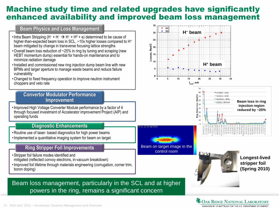
Machine study time and related upgrades have significantly
enhanced availability and improved beam loss management
Beam loss in ring
injection region
reduced by ~25%
H− beam
H+ beam
Longest-lived
stripper foil
(Spring 2010)
Beam loss management, particularly in the SCL and at higher
powers in the ring, remains a significant concern
• Intra Beam Stripping (H− + H− H− + H0 + e) determined to be cause of
higher-than-expected beam loss in SCL, ~10x higher losses compared to H+
beam mitigated by change in transverse focusing lattice strengths
•Overall beam loss reduction of ~25% in ring by tuning and scraping (new HEBT momentum dump) essential for hands-on maintenance and to minimize radiation damage
• Installed and commissioned new ring injection dump beam line with new BPMs and larger aperture to manage waste beams and reduce failure vulnerability
•Changed to fixed frequency operation to improve neutron instrument choppers and veto rate
Beam Physics and Loss Management
• Improved High Voltage Converter Module performance by a factor of 4 through focused investment of Accelerator improvement Project (AIP) and operating funds
Convertor Modulator Performance Improvement
•Routine use of laser- based diagnostics for high power beams
• Implemented a quantitative imaging system for beam on target
Diagnostic Enhancements
•Stripper foil failure modes identified and mitigated (reflected convoy electrons, in-vacuum breakdown)
• Improved foil lifetime through materials engineering (corrugation, corner trim, boron doping)
Ring Stripper Foil Improvements Beam on target image in the
control room

13 SNS AAC 2013 – Accelerator Systems Management and Overview
H-Source and LEBT performance has stabilized but challenges
remain
Three of the five ion sources can now predictably support 1MW operation for up to 6 weeks
•Current decay problem on Sources 2 and 4 resolved
•Three sources now reliably support high-power accelerator operation
Peak Current Capability
•Several sources reliably perform for 6-week cycles without performance degradation
•RF Antenna infant mortality problems are actively managed through quality assurance and contribute to this success
Source Service Cycle
• Introduced frequency hopping in the 2MHz antenna drive to avoid plasma outages near the end of long service cycles
Plasma Outage Management
•Reduced Cesium consumption from 0.5 mg/day to 0.1 mg/day
•High efficiency Cs consumption if ~4000 times less normalized to duty factor when compared with other cesiated H- ion sources
Cesium Consumption Management
38 mA
Antenna current
RF forward power
2 MHz
1.98 MHz (~10ms)
RF refllected power
14 SNS AAC 2013 – Accelerator Systems Management and Overview
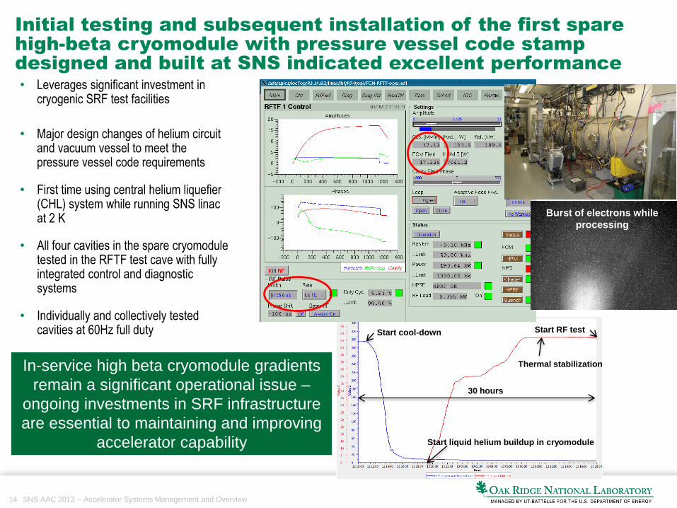
Initial testing and subsequent installation of the first spare
high-beta cryomodule with pressure vessel code stamp
designed and built at SNS indicated excellent performance
Cryomodule in RF test cave
• Leverages significant investment in cryogenic SRF test facilities
• Major design changes of helium circuit and vacuum vessel to meet the pressure vessel code requirements
• First time using central helium liquefier (CHL) system while running SNS linacat 2 K
• All four cavities in the spare cryomoduletested in the RFTF test cave with fully integrated control and diagnostic systems
• Individually and collectively tested cavities at 60Hz full duty Start cool-down
Start liquid helium buildup in cryomodule
Thermal stabilization
Start RF test
30 hours
Burst of electrons while
processing
In-service high beta cryomodule gradients
remain a significant operational issue –
ongoing investments in SRF infrastructure
are essential to maintaining and improving
accelerator capability
15 SNS AAC 2013 – Accelerator Systems Management and Overview
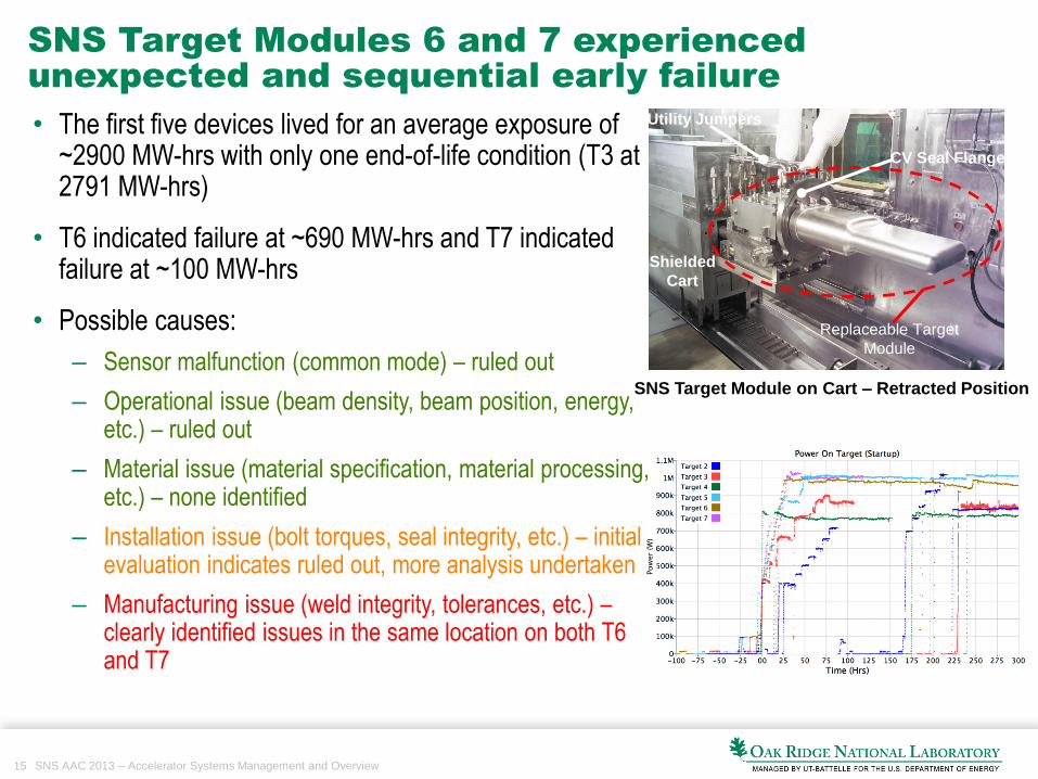
SNS Target Modules 6 and 7 experienced
unexpected and sequential early failure
SNS Target Module on Cart – Retracted Position
CV Seal Flange
Utility Jumpers
Shielded
Cart
Replaceable Target
Module
• The first five devices lived for an average exposure of ~2900 MW-hrs with only one end-of-life condition (T3 at 2791 MW-hrs)
• T6 indicated failure at ~690 MW-hrs and T7 indicated failure at ~100 MW-hrs
• Possible causes:
– Sensor malfunction (common mode) – ruled out
– Operational issue (beam density, beam position, energy, etc.) – ruled out
– Material issue (material specification, material processing, etc.) – none identified
– Installation issue (bolt torques, seal integrity, etc.) – initial evaluation indicates ruled out, more analysis undertaken
– Manufacturing issue (weld integrity, tolerances, etc.) –clearly identified issues in the same location on both T6 and T7

16 SNS AAC 2013 – Accelerator Systems Management and Overview
Were there changes to procedures or operations
that caused these failures?
• Evaluated a substantial amount of data for the installation and operation of Targets 1-7
• Identified four significant changes:– Fixed frequency operation (60 Hz asynchronous with respect
to line voltage) beginning on February 14, 2012 (Targets 5-7) – no correlations identified
– Changes in mercury loop pump differential pressure and system flows a few hundred hours after initial operation (Targets 5 and 6) – correlated with increase in upper knife edge seal pressure leak rate, which is in turn correlated with knife edge seal integrity, which in turn is correlated with installation procedures and bolt torque values – not a causal factor
– Increased torque used to bolt the target module to the target carriage (Targets 6 and 7) – analysis indicates that T6 soft iron seal was partially compromised (installation) and that T7 best correlated with the only known metal-to-metal seal condition (T1) – not a causal factor
– Reduced beam energy from 925 MeV to 895.5 MeV (removed Cryomodule 6 for repair) (Targets 6 and 7) – beam energy will be restored to ~920 MeV with installation of Cryomodule 6, and no obvious significant changes related to energy deposition with this small change in energy
Item Change Description Type Implementation
1 Hardware developed to enable leak testing of mercury loop with Carriage retracted Tooling Target #2
2 Carriage Brake Pin retraction process altered to ensure pins are free Procedural Target #3
3 Counterweight Lift Fixture Stand utilized to hold fixture vertical Tooling Target #3
4 Maxi-Break Hiltap torque wrenches introduced to enable easier torque verification Tooling Target #3
5
Throat openings on open-end wrenches increased slightly to enable easier
installation onto nuts Tooling Target #3
6 15 foot flex hose utilized to replace cumbersome 30 foot hose Tooling Target #3
7 Initial knife edge seal test performed prior to remaining jumper installation Procedural Target #3
8 Began utilization of PT1A wrench for target bolt torquing Tooling Target #3
9
Thru-the-wall manipulators used for N2/He line installation due to better access
than the servo Tooling Target #3
10
Target orientation was reversed on Transfer Bay cart to provide clearance for nose
while in the Transfer Bay Procedural Target #3
11 Hand tools were visibly marked to indicated sizes for better identification Tooling Target #3
12 Nose boot attachment arm modified to enable easier attachment to spent targets Tooling Target #3
13 Inflatable seal preparation procedure modified to remove travel-limiting screws Tooling Target #3
14 Heavy counterweight installation point moved to before jack bolt lowering Procedural Target #3
15 Window flow orifice remove from Seal Plate Tooling Target #3
16
"Installation Cans" used for water and mercury reflange seal rings to ease
installation into hubs Tooling Target #4
17 Leak testing of water loop with Carriage retracted instituted Tooling Target #4
18
Delayed removal and inspection of water/mercury seal rings until full Carriage
retracted to allow better servo access Procedural Target #4
19
Use of "IN" and "OUT" Carriage flags eliminated for all Carriage movements other
than full retraction and full insertion Procedural Target #5
20 New nose spacer incorporated that includes handling features for easier removal Tooling Target #5
21
Installed new upper/lower knife edge seal nitrogen lines to repair line and relocate
pressure transmitters to eliminate Carriage interference Tooling Target #6

17 SNS AAC 2013 – Accelerator Systems Management and Overview
Since FY2009 there has been significant investment
in SNS facilities
• Joint Institute of Neutron Sciences Facility – $8.7 Million
State Investment
• JINS and Guest House Parking Lot Expansion - $ 2.46 Million
• CLO 5th Floor Collaborative Offices - $2.1 Million
• Chestnut Ridge Maintenance Shops - $9.6 Million (FY12/13 – Under Construction)
Institutional Investment
• ORNL Guest House – $8.9 Million
• CLO 2nd Floor Labs – $4.8 Million
• Klystron Gallery Gap Build-out – $1.12 Million
• SRF Laboratory HVAC and Mezzanine – $0.65 Million
• Target Building Chilled Water System Upgrades – $0.59 Million
• CLO Central Control Room and Equipment Room Emergency Generator and UPS – $0.58 Million
SNS Programmatic Investment

18 SNS AAC 2013 – Accelerator Systems Management and Overview
Development is needed to increase source
performance to 1.4 MW
• Improve high beta SRF cavity performance – Plasma processing R&D and in-situ implementation (~$2.3M)
• Superconducting RF facilities and capabilities – Spare medium beta cryomodule, test facility development, Kinney pump, horizontal test facility, cavity chemistry (~$7.9M)
• Cryomodule rework – Two each high and medium beta cryomodules (~$1.0M)
Beam Energy
• For High Voltage Convertor Modulators - Pulse ripple reduction, controller upgrades, IGBT snubbers, HVCM cooling, and alternate topology (~$2.55M)
• Re-engineer all warm linac RF couplers ($0.8M)
Duty Factor
• External antenna development
• Ion source performance development (~$0.3M)
Peak Current
• Damping system for e-p instability, 10µs laser stripping demonstration ($1.5M)
Beam Stability

19 SNS AAC 2013 – Accelerator Systems Management and Overview
We have made good progress in closing
items you identified last year
Area Total Closed OpenGeneral Remarks 1 1
RAD Re-Organization, current operations and ramp-up plans 1 1
Superconducting Linac Performance 2 1 1
High Voltage Converter Modulators 4 4
RF Systems 3 3
Superconducting Linac cryomodules and cryogenics 2
HEBT/Ring/RTBT, Foil Development, Laser Wires and Laser
Stripping3 1 2
Ring beam dynamics 2 2
Target development 3 3
Moderator and reflector improvements 2 2
Proton beam window 1 1
Beam instrumentation systems 3 1 2
Reliability Modeling, Vulnerability Analysis and Spares
Management1 1
Power Upgrade Project 2 1 1

20 SNS AAC 2013 – Accelerator Systems Management and Overview
Summary
• We can operate reproducibly with beam power ~ 1 MW and availability ~ 90%
• While we meet or exceed operating commitments many significant challenges remain
• Our immediate focus is on sustaining availability and continuing operation at ~1 MW (subject to target limitations)
• Our medium term effort will achieve reliable 1.4MW operation by 2017, lay the foundation for 3MW capability and maintain the potential to carry out the Second Target Station project
• Institutional commitment has been essential to our success
The hard work, dedication and talent of the SNS staff enable these achievements


![Simulations for the SNS Linac - CERN › HB2010 › papers › mopd56.pdf · accelerator code which include s realistic 3D space charge calculations [7]. At SNS it is used for offline](https://img.pdfslide.net/doc/110x75/5f0f5d557e708231d443cb8d/simulations-for-the-sns-linac-cern-a-hb2010-a-papers-a-mopd56pdf-accelerator.jpg)