Embed Size (px)
Citation preview
ACCELERATORS IN NUCLEARENERGY PROGRAMME
Srikumar BanerjeeDepartment of Atomic Energy
INDIA
Workshop onWorkshop onAsian Forum for Accelerators & DetectorsAsian Forum for Accelerators & Detectors
(AFAD-2012)(AFAD-2012)February 6, 2012
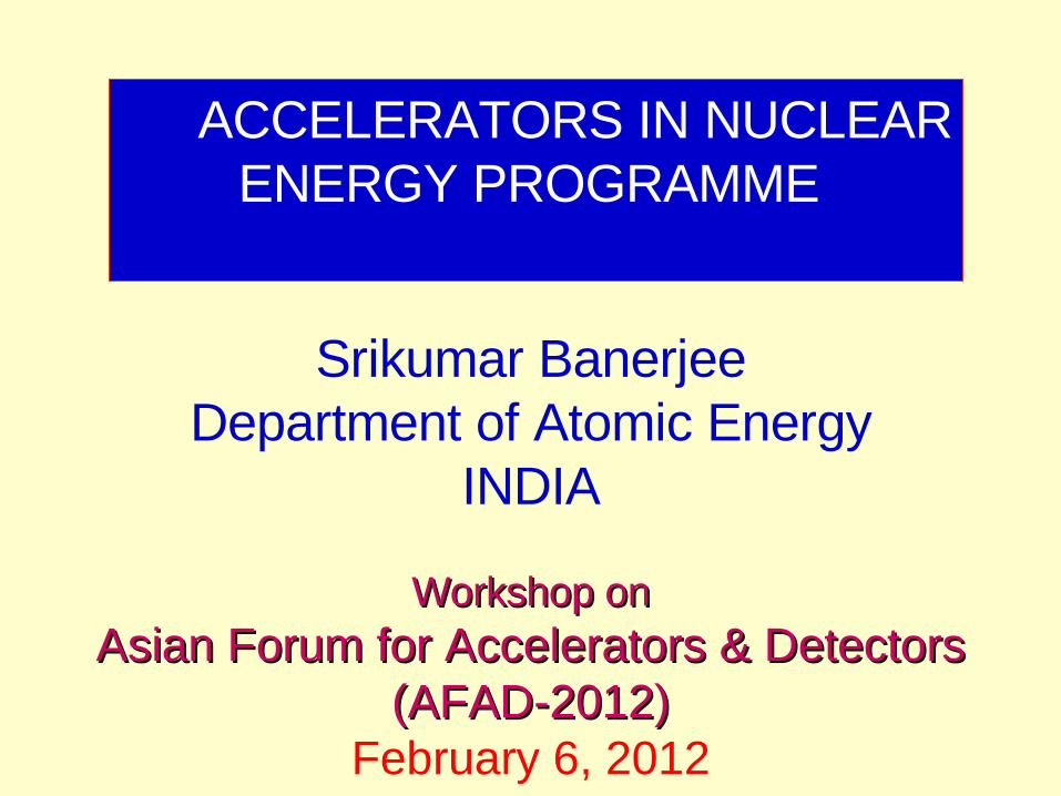
ACCELERATORS
ASTRO-NUCLEAR
&PARTICLEPHYSICS NATIONAL
SECURITY
INDUSTRY-Thin LayerActivation
BIOSCIENCES-THERAPY
RADIOISOTOPEPRODUCTION
NUCLEAR TECHNIQUES
RBS, NRA, AMS,ERDA,
PIXEMATERIAL
MODIFICATIONCHARACTERISATION
ACCELERATORDRIVEN SYSTEM(ADS)
CENTRAL ROLE OF ACCELERATORSCENTRAL ROLE OF ACCELERATORS

ACCELERATORS IN THE
FIELD OF MEDICINE
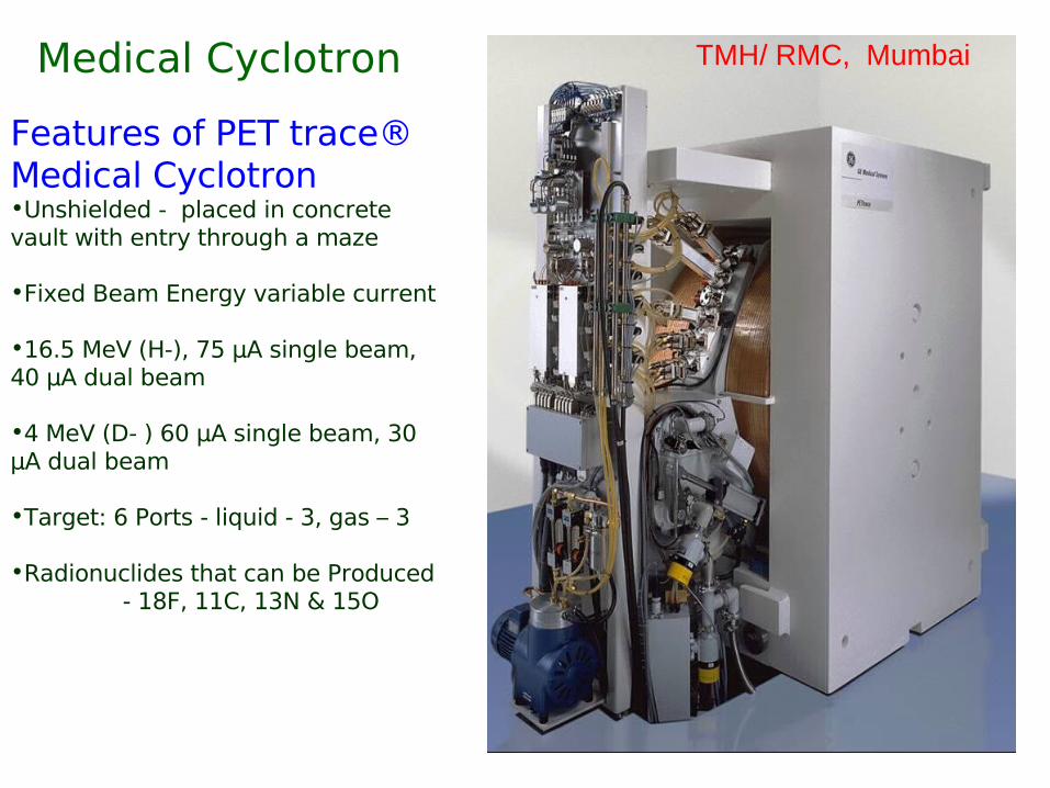
Medical Cyclotron
Features of PET trace® Medical Cyclotron•Unshielded - placed in concrete vault with entry through a maze
•Fixed Beam Energy variable current
•16.5 MeV (H-), 75 µA single beam, 40 µA dual beam
•4 MeV (D- ) 60 µA single beam, 30 µA dual beam
•Target: 6 Ports - liquid - 3, gas – 3
•Radionuclides that can be Produced - 18F, 11C, 13N & 15O
TMH/ RMC, Mumbai
Medical Isotope Shortage !
NRU Reactor at Canada – not functional
HRF at Netherlands – major maintenance
Ageing existing Reactors
Crisis of supply of Mo-99
Look beyond the Reactor Route
Possible Accelerator Methods for production of 99Mo
Accelerator Route
High Energy Spallation Source - with Neutrons From the Primary target to initiate Fission in the surrounding 235U blanket
Medium sized Cyclotrons to produce 99 MoThrough the Reaction 100 Mo ( p,pn) 99Mo( Requires enriched isotopeProduction probability is too low)
MEDICAL CYCLOTRON AT VECC
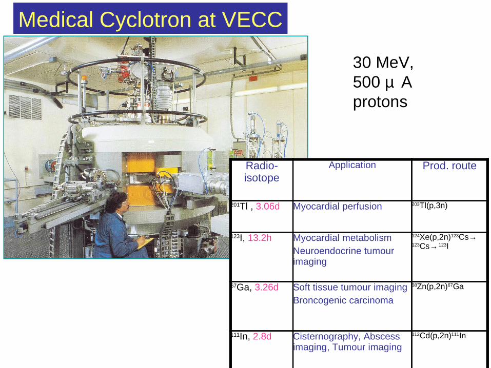
Medical Cyclotron at VECC
Radio-isotope
Application Prod. route
201Tl , 3.06d Myocardial perfusion 203Tl(p,3n)
123I, 13.2h Myocardial metabolismNeuroendocrine tumour imaging
124Xe(p,2n)123Cs→ 123Cs→ 123I
67Ga, 3.26d Soft tissue tumour imagingBroncogenic carcinoma
68Zn(p,2n)67Ga
111In, 2.8d Cisternography, Abscess imaging, Tumour imaging
112Cd(p,2n)111In
30 MeV,500 µ Aprotons
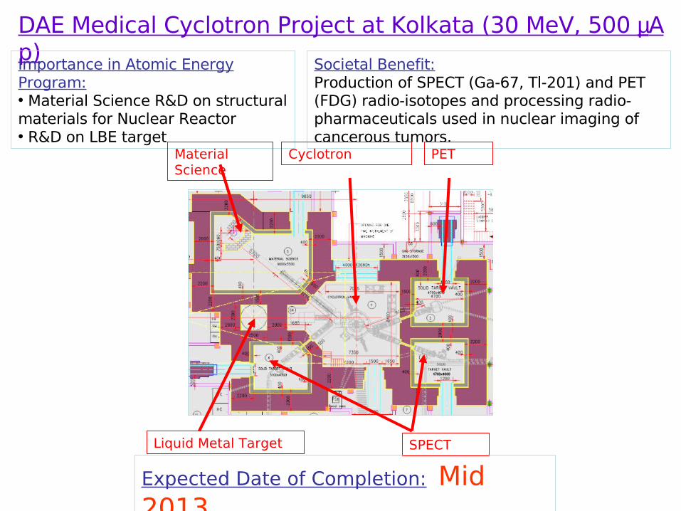
DAE Medical Cyclotron Project at Kolkata (30 MeV, 500 µA p)
Societal Benefit: Production of SPECT (Ga-67, Tl-201) and PET (FDG) radio-isotopes and processing radio-pharmaceuticals used in nuclear imaging of cancerous tumors.
Importance in Atomic Energy Program: • Material Science R&D on structural materials for Nuclear Reactor• R&D on LBE target
Cyclotron
SPECT
PETMaterial Science
Liquid Metal Target
Expected Date of Completion: Mid 2013

ACCELERATORS IN THE
FIELD OF BASIC RESEARCH
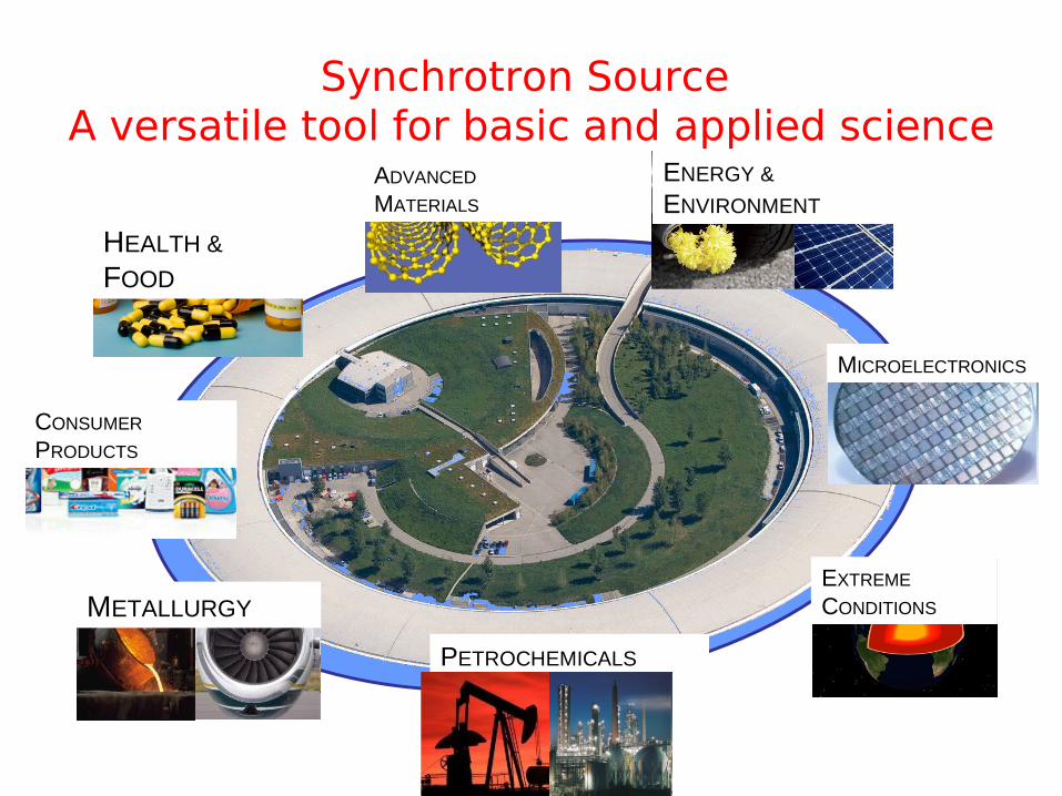
CONSUMER PRODUCTS
HEALTH &
FOOD
METALLURGY
ENERGY & ENVIRONMENT
MICROELECTRONICS
EXTREME CONDITIONS
PETROCHEMICALS
ADVANCED MATERIALS
Synchrotron Source A versatile tool for basic and applied science

Indian Synchrotron Scenario for Material Research
• First Indian machine INDUS-1 (450MeV) is operational now (for VUV and soft x-ray) and good publications have appeared already.
• X-ray synchrotron INDUS-2 is operating regularly at 2.0GeV and has been tested at 2.5GeV
• Saha Institute has installed one of the beamlines at INDUS-2.• DST supported Indian beamlines at Japanese synchrotron Photon
Factory have been set up by SINP. SINP is also coordinating access to ALL beamlines of PETRA-III, DESY. NEED to increase “User-base”
• There is a need of High brilliance High-energy synchrotron source for advanced research in India in the fields of Materials, Disease Biology and Energy. This project will also enhance our capabilities in the fields of Accelerator Science – Very important for DAE.
• In a meeting of international experts at SINP on Nov 11 & 12, 2010, it was suggested that a 6 GeV 200mA synchrotron source with around 1500 m circumference will be an ideal choice and this facility may become best in the world for material research. SINP has proposed this project and DAE is taking take up in Planning Commission.
Three major areas: Imaging, Diffraction and Spectroscopy

Indus-2 Synchrotron Radiation Source
550 MeV, 3-4 mA, 1 Hz
Indus-2, 2.5 GeV
SR
TL-3
TL-1
Indus-1 ( 450 MeV )
Booster Synchrotron
Microtron
Indus-22.5 GeV ring
• Indus-2 operating in round the clock mode at 2 GeV, 100 mA since March 2010
• Beam life time at 2GeV, 100 mA ~ 22 hrs
• Six beamlines commissioned and made available to researchers
Indus-2 reached a major milestone on December 6, 2011
Operation at 2.5 GeV energy, 100mA beam current
Raja Ramanna Centre for Advanced Technology, Indore
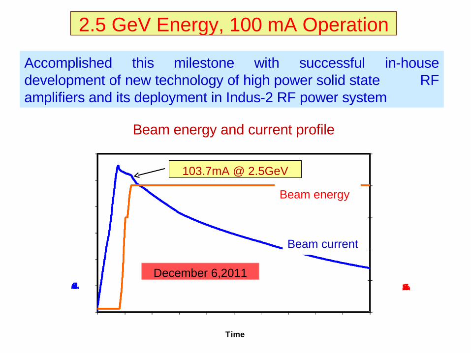
2.5 GeV Energy, 100 mA Operation
Accomplished this milestone with successful in-house development of new technology of high power solid state RF amplifiers and its deployment in Indus-2 RF power system
Beam energy and current profile
500
1111
1111
2000
2500
3000
0
20
40
60
80
100
111
:19 04 :11 11 :11 11 :11 11 :11 11 :11 11 :1 11 :1 11 :1 11 :3 47 :1 11
Beam energy (MeV)Beam current (mA)
Time
103.7mA @ 2.5GeV
December 6,2011
Beam energy
Beam current
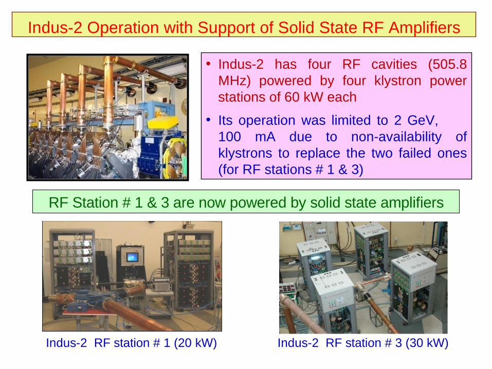
Indus-2 Operation with Support of Solid State RF Amplifiers
RF Station # 1 & 3 are now powered by solid state amplifiers
Indus-2 RF station # 1 (20 kW) Indus-2 RF station # 3 (30 kW)
• Indus-2 has four RF cavities (505.8 MHz) powered by four klystron power stations of 60 kW each
• Its operation was limited to 2 GeV, 100 mA due to non-availability of klystrons to replace the two failed ones (for RF stations # 1 & 3)

Joint statement issued by the PM of India and Japan"Science and Technology” August 2007
21. The two leaders welcomed the signing of the Letter of Intent on Scientific and Technological Cooperation between the Department of Science and Technology of India (DST) and the High Energy Accelerator Research Organization of Japan (KEK) on 24 July 2007, recalling the discussion in the India-Japan Science Council co-hosted by DST and the Japan Society for the Promotion of Science."
H. K. Singh, Ambassador of India to Japan (right), and O. Shimomura, Director of Institute of Materials Structure Science in KEK (left) at the MoU at the signing ceremony in presence of visiting Prime Minister Dr. Manmahan Singh.
LOI signed by Prof. C.N.R. Rao &Prof. O. Shimomura and by Prof. M. Nomura & Prof. M.K. Sanyal
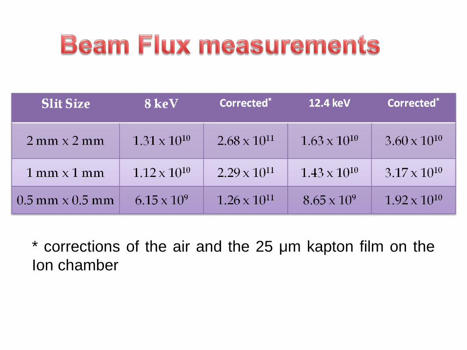
* corrections of the air and the 25 μm kapton film on the Ion chamber
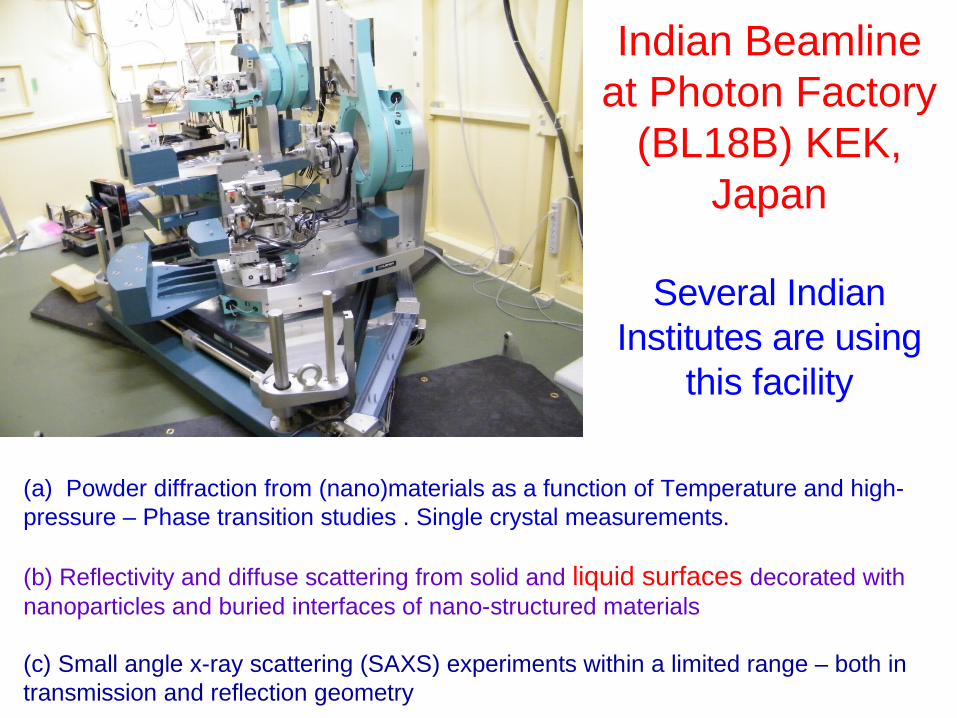
(a) Powder diffraction from (nano)materials as a function of Temperature and high-pressure – Phase transition studies . Single crystal measurements.
(b) Reflectivity and diffuse scattering from solid and liquid surfaces decorated with nanoparticles and buried interfaces of nano-structured materials
(c) Small angle x-ray scattering (SAXS) experiments within a limited range – both in transmission and reflection geometry
Indian Beamline at Photon Factory
(BL18B) KEK, Japan
Several Indian Institutes are using
this facility
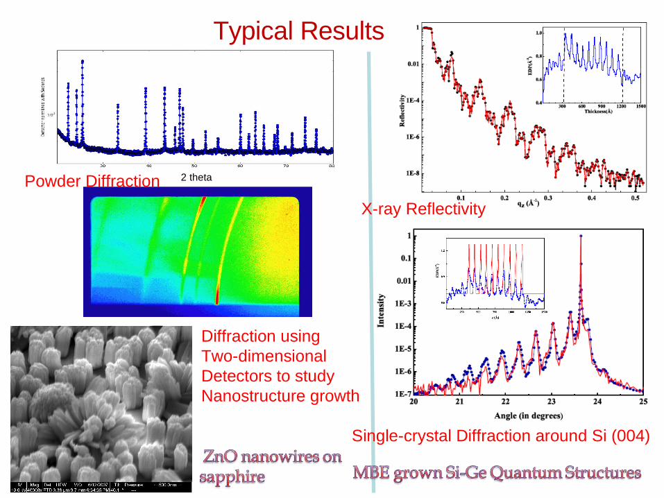
2 theta
Diffraction usingTwo-dimensionalDetectors to studyNanostructure growth
Typical Results
X-ray Reflectivity
Powder Diffraction
Single-crystal Diffraction around Si (004)
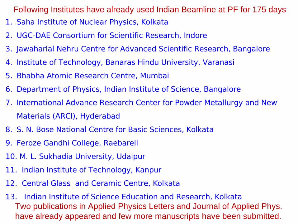
1. Saha Institute of Nuclear Physics, Kolkata
2. UGC-DAE Consortium for Scientific Research, Indore
3. Jawaharlal Nehru Centre for Advanced Scientific Research, Bangalore
4. Institute of Technology, Banaras Hindu University, Varanasi
5. Bhabha Atomic Research Centre, Mumbai
6. Department of Physics, Indian Institute of Science, Bangalore
7. International Advance Research Center for Powder Metallurgy and New
Materials (ARCI), Hyderabad
8. S. N. Bose National Centre for Basic Sciences, Kolkata
9. Feroze Gandhi College, Raebareli
10. M. L. Sukhadia University, Udaipur
11. Indian Institute of Technology, Kanpur
12. Central Glass and Ceramic Centre, Kolkata
13. Indian Institute of Science Education and Research, Kolkata
Following Institutes have already used Indian Beamline at PF for 175 days
Two publications in Applied Physics Letters and Journal of Applied Phys.have already appeared and few more manuscripts have been submitted.
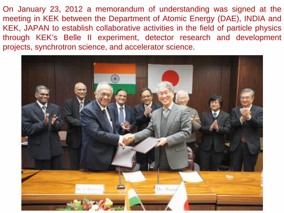
On January 23, 2012 a memorandum of understanding was signed at the meeting in KEK between the Department of Atomic Energy (DAE), INDIA and KEK, JAPAN to establish collaborative activities in the field of particle physics through KEK’s Belle II experiment, detector research and development projects, synchrotron science, and accelerator science.
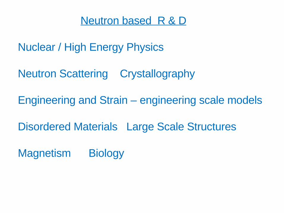
Neutron based R & D
Nuclear / High Energy Physics
Neutron Scattering Crystallography
Engineering and Strain – engineering scale models
Disordered Materials Large Scale Structures
Magnetism Biology

ACCELERATORS IN
NATIONAL SECURITY
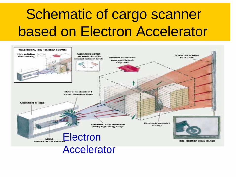
Schematic of cargo scanner based on Electron Accelerator
ElectronAccelerator
27
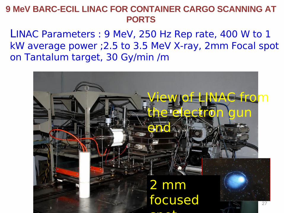
9 MeV BARC-ECIL LINAC FOR CONTAINER CARGO SCANNING AT PORTS
LINAC Parameters : 9 MeV, 250 Hz Rep rate, 400 W to 1 kW average power ;2.5 to 3.5 MeV X-ray, 2mm Focal spot on Tantalum target, 30 Gy/min /m
View of LINAC from the electron gun end
2 mm focused spot
ACCELERATORS IN THE FIELD OF
NUCLEAR ENERGY
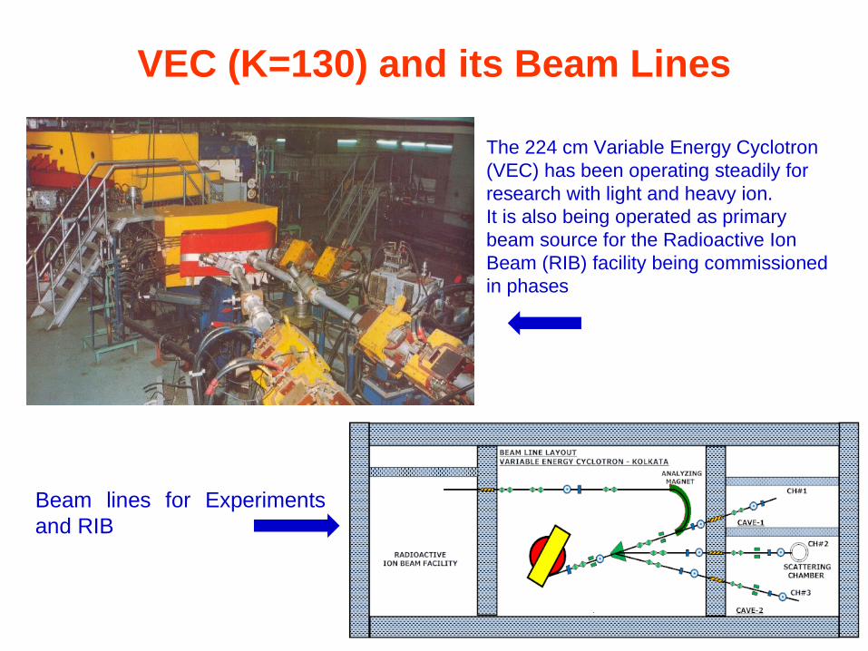
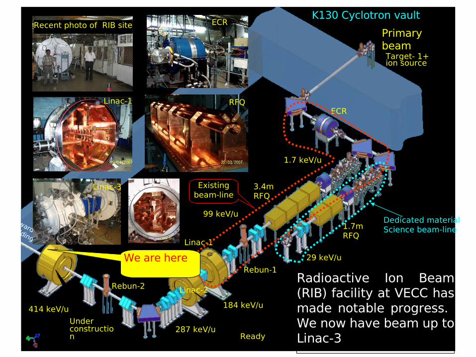
VEC (K=130) and its Beam Lines
Beam lines for Experiments and RIB
The 224 cm Variable Energy Cyclotron(VEC) has been operating steadily for research with light and heavy ion. It is also being operated as primary beam source for the Radioactive Ion Beam (RIB) facility being commissioned in phases
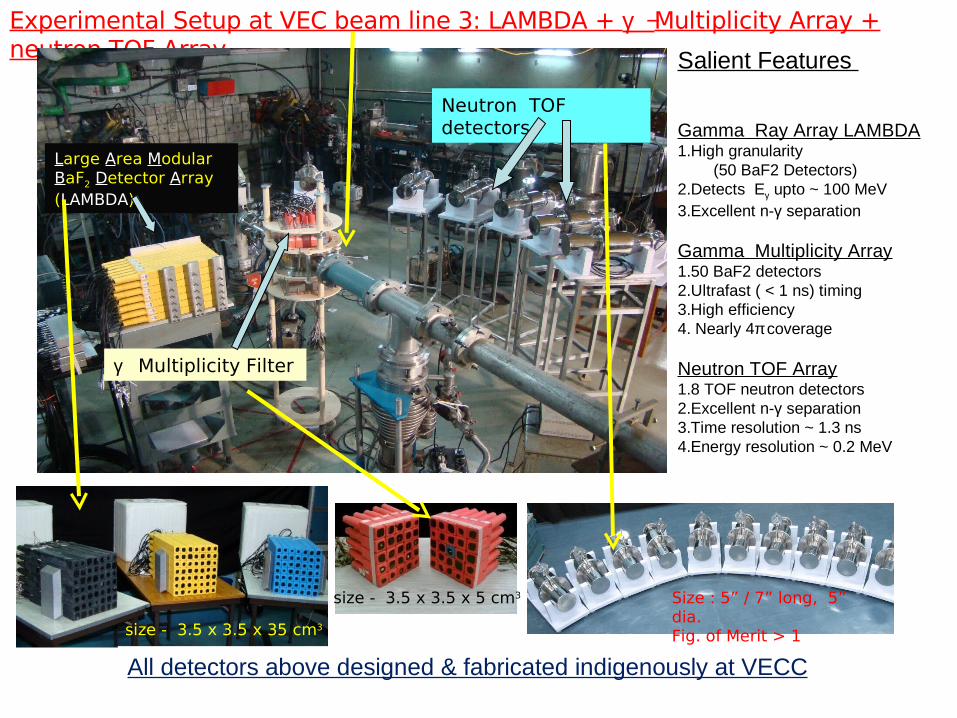
Experimental Setup at VEC beam line 3: LAMBDA + γ −Multiplicity Array + neutron TOF Array
Neutron TOF detectors
γ Multiplicity Filter
Large Area Modular BaF2 Detector Array (LAMBDA)
Salient Features
Gamma Ray Array LAMBDA1.High granularity (50 BaF2 Detectors)2.Detects Eγ upto ~ 100 MeV3.Excellent n-γ separation
Gamma Multiplicity Array1.50 BaF2 detectors2.Ultrafast ( < 1 ns) timing3.High efficiency4. Nearly 4π coverage
Neutron TOF Array1.8 TOF neutron detectors2.Excellent n-γ separation3.Time resolution ~ 1.3 ns4.Energy resolution ~ 0.2 MeV
size - 3.5 x 3.5 x 35 cm3
size - 3.5 x 3.5 x 5 cm3 Size : 5” / 7” long, 5” dia.Fig. of Merit > 1
All detectors above designed & fabricated indigenously at VECC
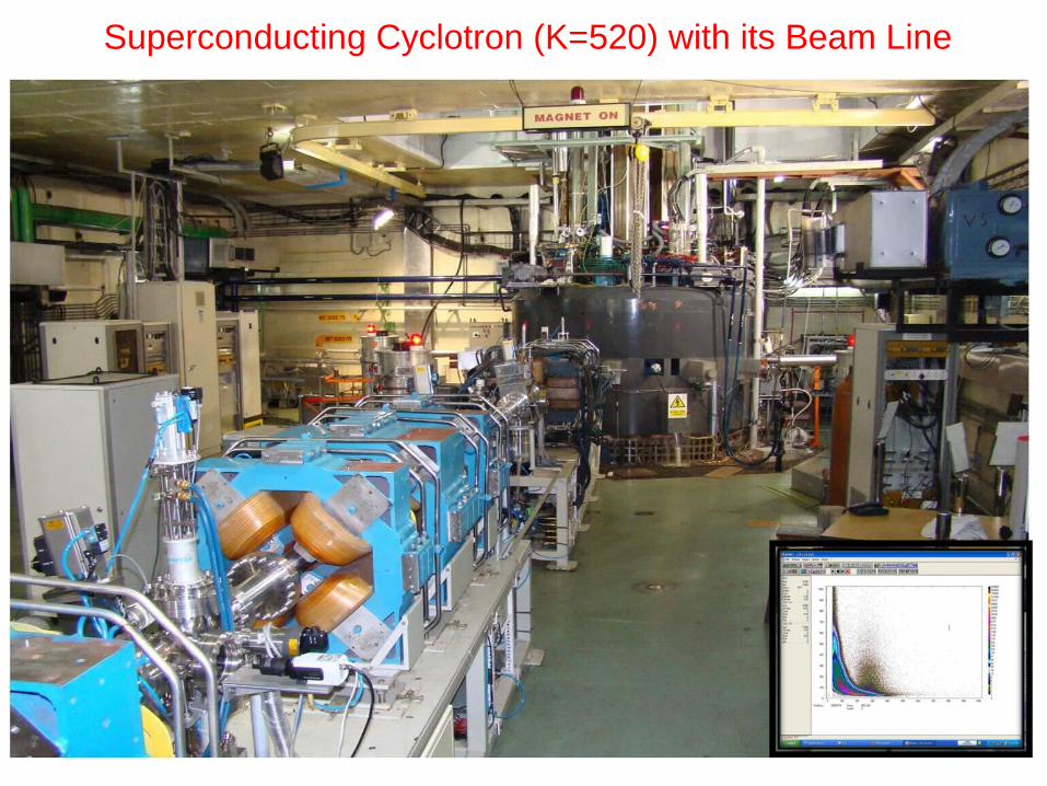
Superconducting Cyclotron (K=520) with its Beam Line
ECR
3.4m RFQ
1.7 keV/u
Target- 1+ ion source
1.7m RFQ
Linac-1
Linac-2
Linac-3
Rebun-1
Rebun-2
29 keV/u
99 keV/u
287 keV/u
414 keV/u 184 keV/u
K130 Cyclotron vault
Primary beam
Radioactive Ion Beam (RIB) facility at VECC has made notable progress. We now have beam up to Linac-3
Towards new
building
Under construction
Existing beam-line
Ready
Dedicated materialScience beam-line
Linac-1 RFQ
ECRRecent photo of RIB site
We are here
Linac-3
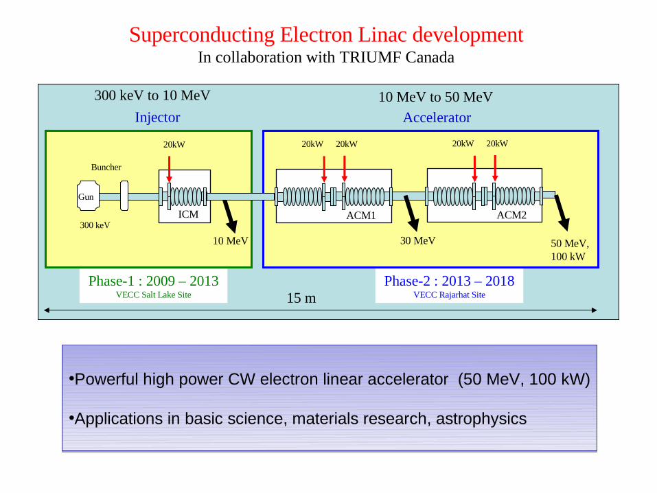
Superconducting Electron Linac developmentIn collaboration with TRIUMF Canada
Phase-1 : 2009 – 2013VECC Salt Lake Site
10 MeV
Injector
20kW
ICM
Gun
Buncher
300 keV
Phase-2 : 2013 – 2018VECC Rajarhat Site
Accelerator
300 keV to 10 MeV 10 MeV to 50 MeV
30 MeV
20kW 20kW
ACM1
20kW 20kW
ACM2
50 MeV, 100 kW
15 m
•Powerful high power CW electron linear accelerator (50 MeV, 100 kW)
•Applications in basic science, materials research, astrophysics
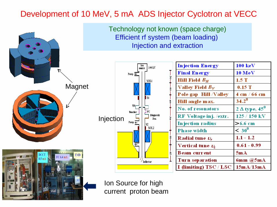
Development of 10 MeV, 5 mA ADS Injector Cyclotron at VECC
Technology not known (space charge)Efficient rf system (beam loading)
Injection and extraction
Magnet
Ion Source for high current proton beam
Injection

For Long Term Energy Security , India has a robust Three Stage Power Programme in place.
Development of Thorium Based Reactor Systems for sustainable Nuclear Energy belongs to the Third stage
Prospects of Accelerators in Nuclear Energy Programme in this context
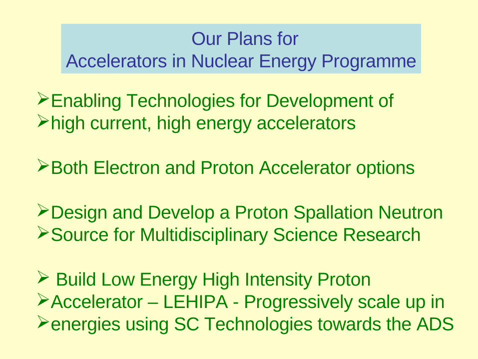
Our Plans for Accelerators in Nuclear Energy Programme
Enabling Technologies for Development ofhigh current, high energy accelerators
Both Electron and Proton Accelerator options
Design and Develop a Proton Spallation NeutronSource for Multidisciplinary Science Research
Build Low Energy High Intensity Proton Accelerator – LEHIPA - Progressively scale up inenergies using SC Technologies towards the ADS
2
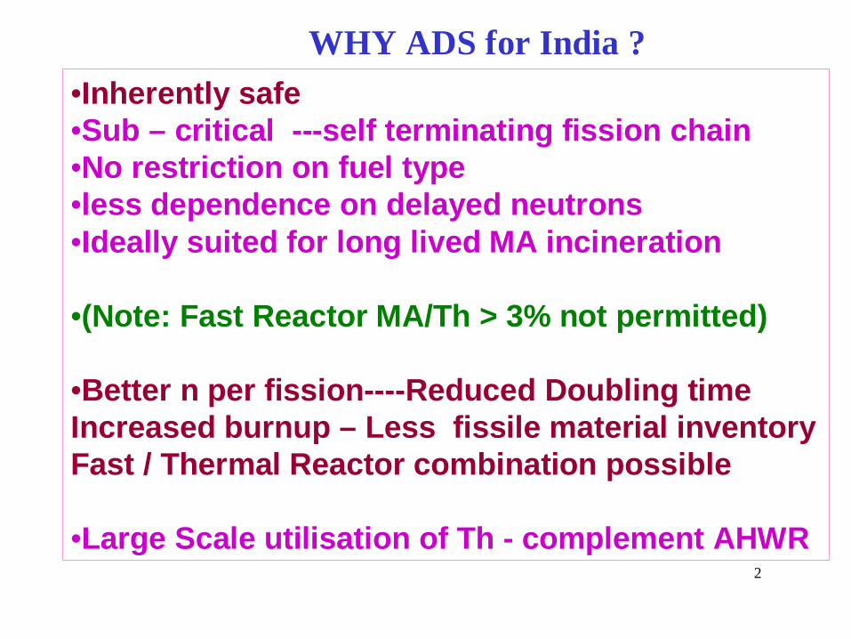
WHY ADS for India ?
•Inherently safe•Sub – critical ---self terminating fission chain•No restriction on fuel type •less dependence on delayed neutrons•Ideally suited for long lived MA incineration
•(Note: Fast Reactor MA/Th > 3% not permitted)
•Better n per fission----Reduced Doubling timeIncreased burnup – Less fissile material inventoryFast / Thermal Reactor combination possible
•Large Scale utilisation of Th - complement AHWR
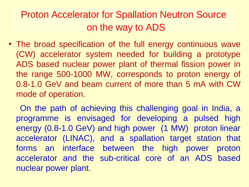
Proton Accelerator for Spallation Neutron Source on the way to ADS
• The broad specification of the full energy continuous wave (CW) accelerator system needed for building a prototype ADS based nuclear power plant of thermal fission power in the range 500-1000 MW, corresponds to proton energy of 0.8-1.0 GeV and beam current of more than 5 mA with CW mode of operation.
On the path of achieving this challenging goal in India, a programme is envisaged for developing a pulsed high energy (0.8-1.0 GeV) and high power (1 MW) proton linear accelerator (LINAC), and a spallation target station that forms an interface between the high power proton accelerator and the sub-critical core of an ADS based nuclear power plant.
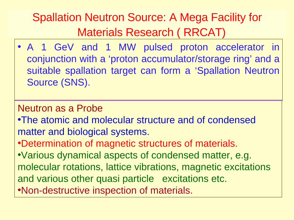
Spallation Neutron Source: A Mega Facility for Materials Research ( RRCAT)
• A 1 GeV and 1 MW pulsed proton accelerator in conjunction with a ‘proton accumulator/storage ring’ and a suitable spallation target can form a ‘Spallation Neutron Source (SNS).
Neutron as a Probe•The atomic and molecular structure and of condensed matter and biological systems. •Determination of magnetic structures of materials.•Various dynamical aspects of condensed matter, e.g. molecular rotations, lattice vibrations, magnetic excitations and various other quasi particle excitations etc.•Non-destructive inspection of materials.
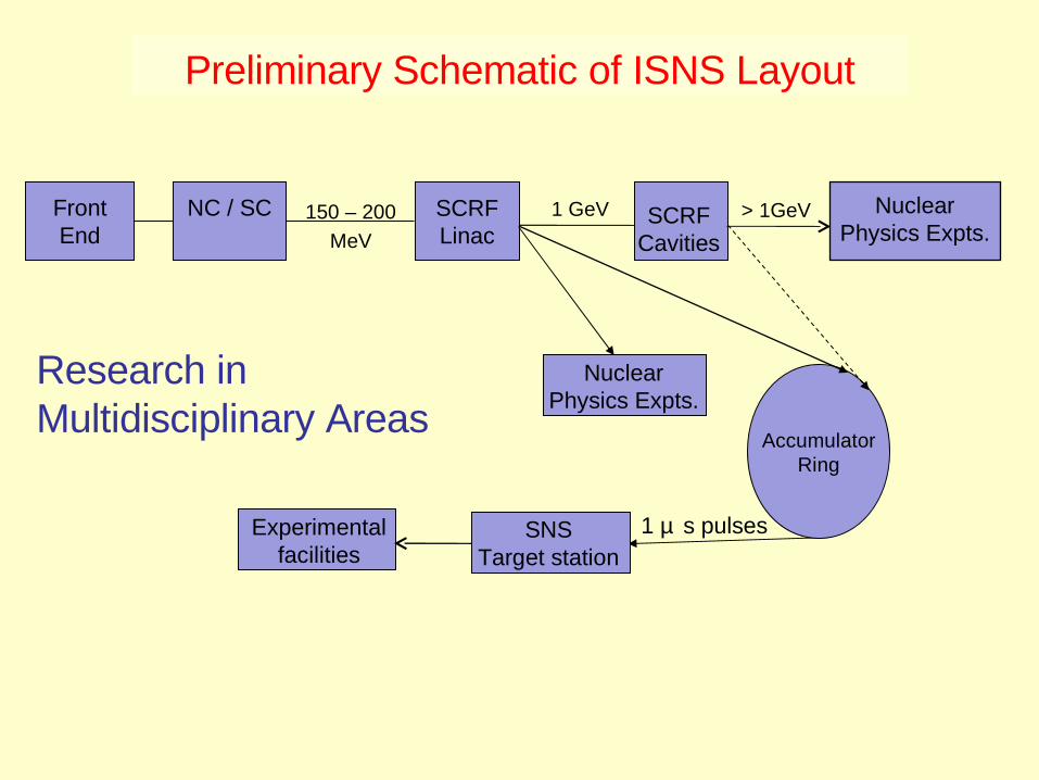
Preliminary Schematic of ISNS Layout
Front End
SCRF Linac
1 GeV
Accumulator Ring
SNSTarget station
SCRF Cavities
> 1GeV Nuclear Physics Expts.
NC / SC 150 – 200
MeV
Nuclear Physics Expts.
1 µ s pulsesExperimental facilities
Research inMultidisciplinary Areas


Technologies for ADS• High power proton accelerator: 1 GeV, cw or high
duty factor & (average) current• High beam current front-end : low random beam losses for
minimal radio-activation of hardware• Superconducting RF cavities: high electrical efficiency &
large aperture for beam• RF power systems: high reliability against random beam trips-
redundant & standby hardware.
• Spallation target & associated process system.• Molten heavy metal for intense volumetric beam power
density• Materials: resistance to neutron irradiation & liquid metal
corrosion at high-temperature.
• Sub-critical reactor• Optimized asTRU transmuter or for thorium fuel-cycle.• Configuration: technology issues- fast & thermal neutrons.• Transients & safety studies- beam trips, reactivity swings.
44


46
Ongoing Indian activities in ADS program
Design studies of a 1 GeV, 30 mA proton linac. Development of 20 MeV high current proton linac for
front-end accelerator of ADS. Construction of LBE experimental loop for design
validation and materials tests for spallation target module.
Superconducting Cavity Development/ High Power RF instrumentation
Development of computational tools and data for neutronics of spallation target and coupled sub-critical reactor.
Experimental validation of reactor physics codes and data with 14-MeV neutrons in sub-critical core at PURNIMA labs.
.

Development of 1.3 GHz, β = 1 SRF Cavity Forming and Machining of Half Cells 2008-2011
Formed Niobium Half cellInspection on CMM
Forming process MachiningHalf Cell Tooling (Aluminum alloy 7075-T6 from Fermilab)
Improvement - rubber pad forming tooling completed
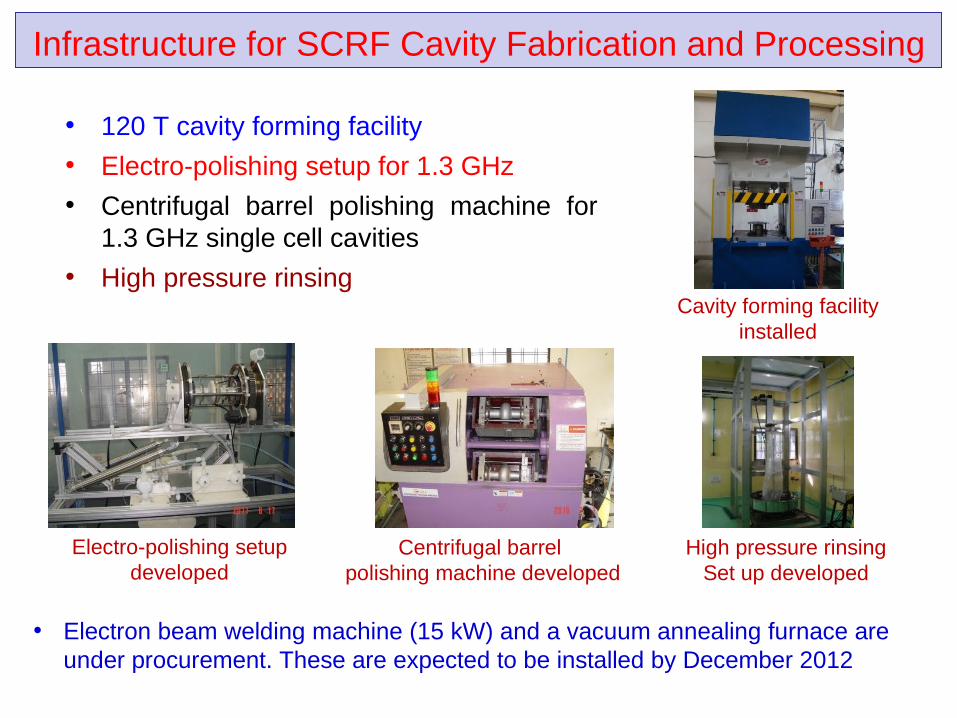
• 120 T cavity forming facility
• Electro-polishing setup for 1.3 GHz
• Centrifugal barrel polishing machine for 1.3 GHz single cell cavities
• High pressure rinsing
Infrastructure for SCRF Cavity Fabrication and Processing
Electro-polishing setup developed
Cavity forming facility installed
Centrifugal barrel polishing machine developed
High pressure rinsing Set up developed
• Electron beam welding machine (15 kW) and a vacuum annealing furnace are under procurement. These are expected to be installed by December 2012
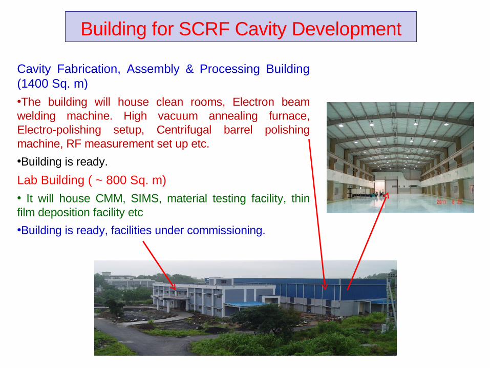
Cavity Fabrication, Assembly & Processing Building (1400 Sq. m)
•The building will house clean rooms, Electron beam welding machine. High vacuum annealing furnace, Electro-polishing setup, Centrifugal barrel polishing machine, RF measurement set up etc.
•Building is ready.
Lab Building ( ~ 800 Sq. m)
• It will house CMM, SIMS, material testing facility, thin film deposition facility etc
•Building is ready, facilities under commissioning.
Building for SCRF Cavity Development
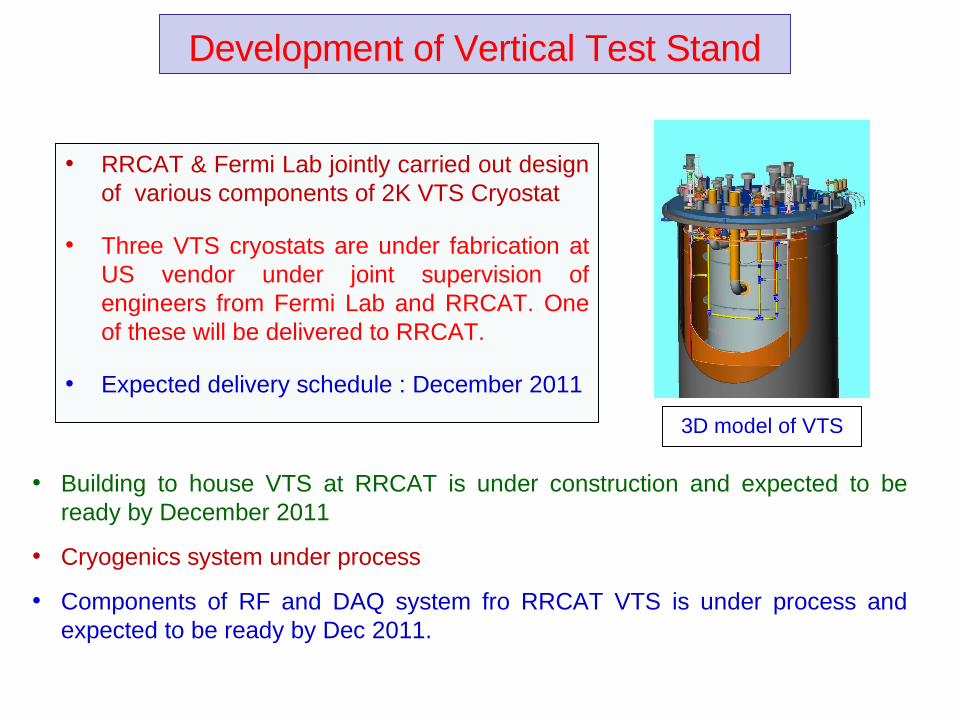
• RRCAT & Fermi Lab jointly carried out design of various components of 2K VTS Cryostat
• Three VTS cryostats are under fabrication at US vendor under joint supervision of engineers from Fermi Lab and RRCAT. One of these will be delivered to RRCAT.
• Expected delivery schedule : December 2011
Development of Vertical Test Stand
3D model of VTS
• Building to house VTS at RRCAT is under construction and expected to be ready by December 2011
• Cryogenics system under process
• Components of RF and DAQ system fro RRCAT VTS is under process and expected to be ready by Dec 2011.
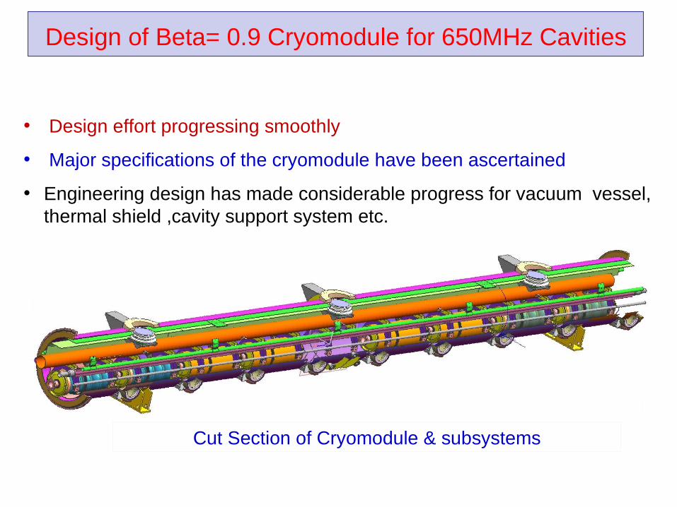
Design of Beta= 0.9 Cryomodule for 650MHz Cavities
• Design effort progressing smoothly
• Major specifications of the cryomodule have been ascertained
• Engineering design has made considerable progress for vacuum vessel, thermal shield ,cavity support system etc.
Cut Section of Cryomodule & subsystems
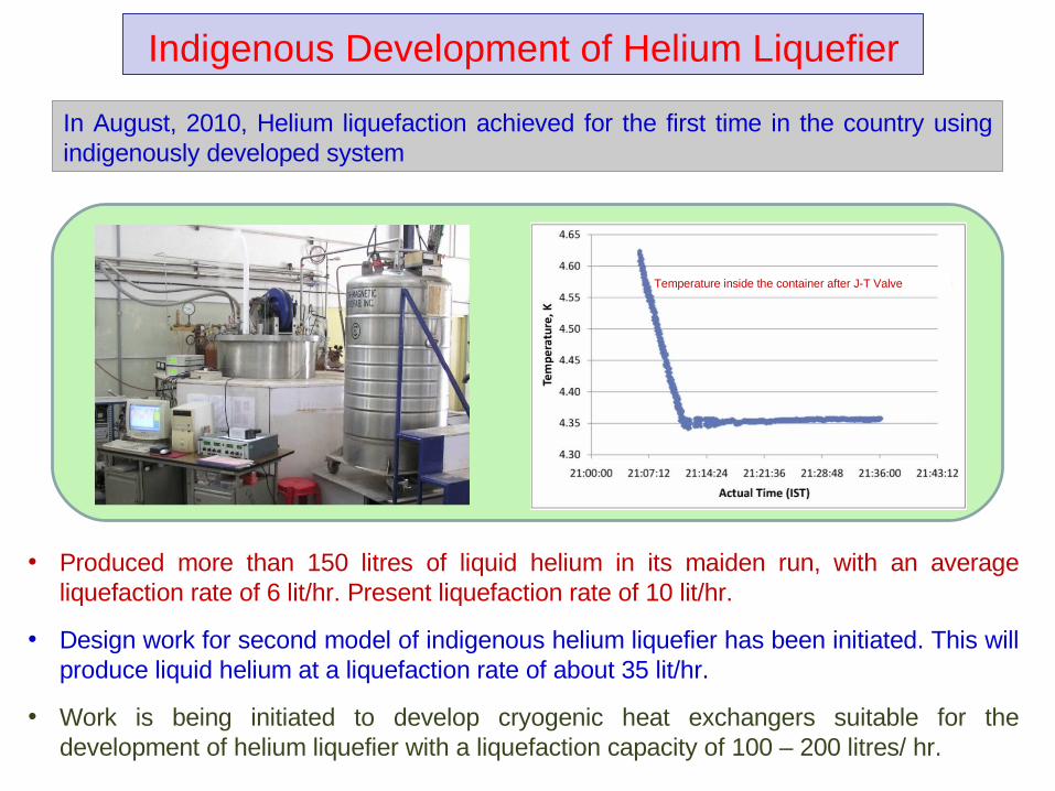
Indigenous Development of Helium Liquefier
In August, 2010, Helium liquefaction achieved for the first time in the country using indigenously developed system
• Produced more than 150 litres of liquid helium in its maiden run, with an average liquefaction rate of 6 lit/hr. Present liquefaction rate of 10 lit/hr.
• Design work for second model of indigenous helium liquefier has been initiated. This will produce liquid helium at a liquefaction rate of about 35 lit/hr.
• Work is being initiated to develop cryogenic heat exchangers suitable for the development of helium liquefier with a liquefaction capacity of 100 – 200 litres/ hr.
Temperature inside the container after J-T Valve
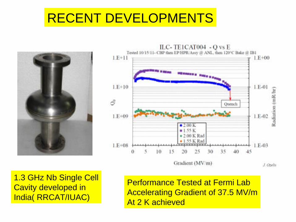
RECENT DEVELOPMENTS
1.3 GHz Nb Single CellCavity developed inIndia( RRCAT/IUAC)
Performance Tested at Fermi LabAccelerating Gradient of 37.5 MV/mAt 2 K achieved
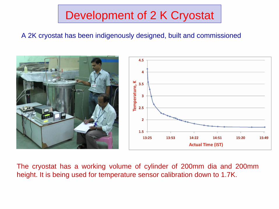
Development of 2 K Cryostat
A 2K cryostat has been indigenously designed, built and commissioned
The cryostat has a working volume of cylinder of 200mm dia and 200mm height. It is being used for temperature sensor calibration down to 1.7K.
• Niobium-based superconducting materials with optimized physical and metallurgical properties for fabrication of energy efficient and cost effective SC-RF accelerator structure.
• Specific roles of lower critical magnetic field (HC1) and BCS surface resistance (RBCS) on the achievable accelerating gradients in SCRF-cavities.
• Newer Nb, Ti and Mo based superconducting alloys for large current carrying applications.
Superconducting Materials R&D at RRCAT
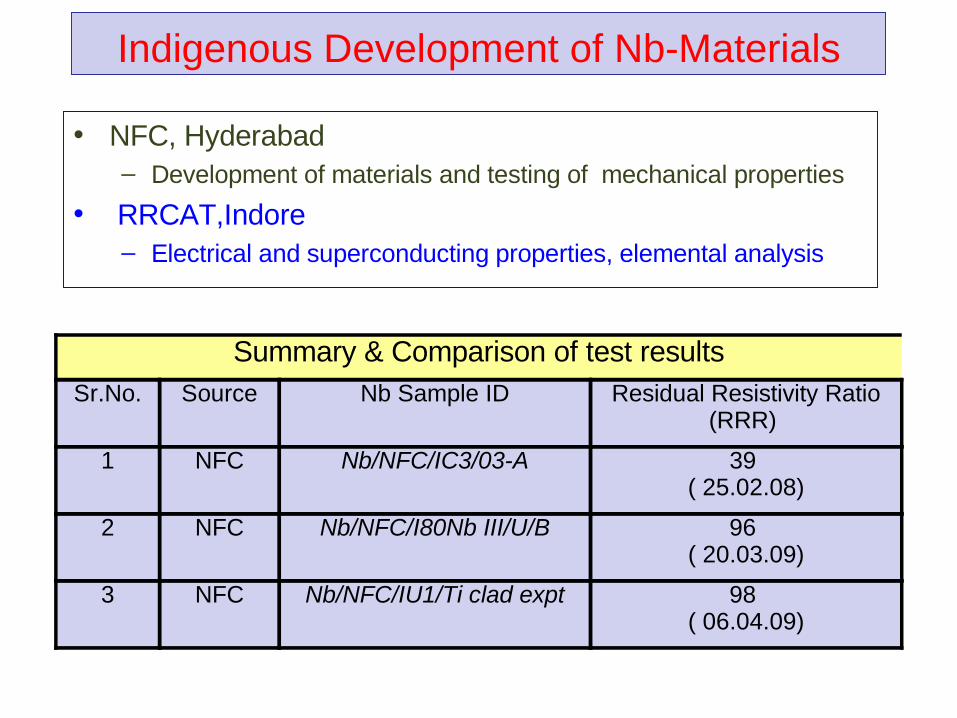
Indigenous Development of Nb-Materials
• NFC, Hyderabad – Development of materials and testing of mechanical properties
• RRCAT,Indore – Electrical and superconducting properties, elemental analysis
Summary & Comparison of test resultsSr.No. Source Nb Sample ID Residual Resistivity Ratio
(RRR)
1 NFC Nb/NFC/IC3/03-A 39 ( 25.02.08)
2 NFC Nb/NFC/I80Nb III/U/B 96 ( 20.03.09)
3 NFC Nb/NFC/IU1/Ti clad expt 98 ( 06.04.09)
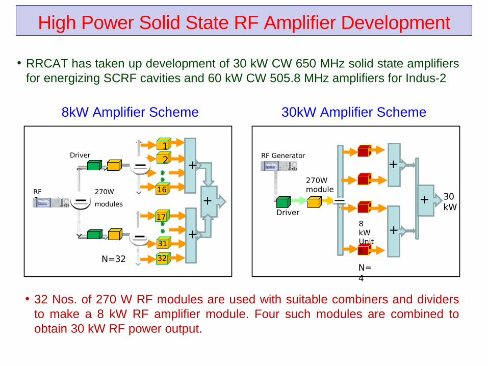
High Power Solid State RF Amplifier Development
8kW Amplifier Scheme 30kW Amplifier Scheme
• RRCAT has taken up development of 30 kW CW 650 MHz solid state amplifiers for energizing SCRF cavities and 60 kW CW 505.8 MHz amplifiers for Indus-2
N=32
1
2
31
32
Driver
270W
modules +RF Generator
16
17
+
+
N=4
30 kW
RF Generator
Driver
270W module
8 kW Units
+
+
+
• 32 Nos. of 270 W RF modules are used with suitable combiners and dividers to make a 8 kW RF amplifier module. Four such modules are combined to obtain 30 kW RF power output.
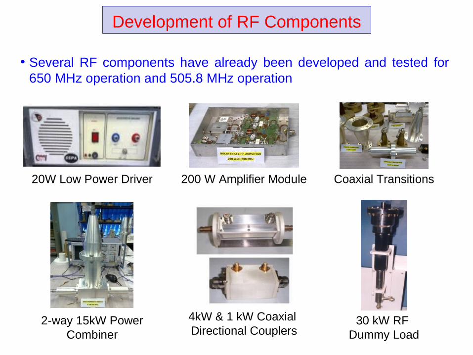
Development of RF Components
• Several RF components have already been developed and tested for 650 MHz operation and 505.8 MHz operation
200 W Amplifier Module20W Low Power Driver Coaxial Transitions
2-way 15kW Power Combiner
30 kW RF Dummy Load
4kW & 1 kW Coaxial Directional Couplers
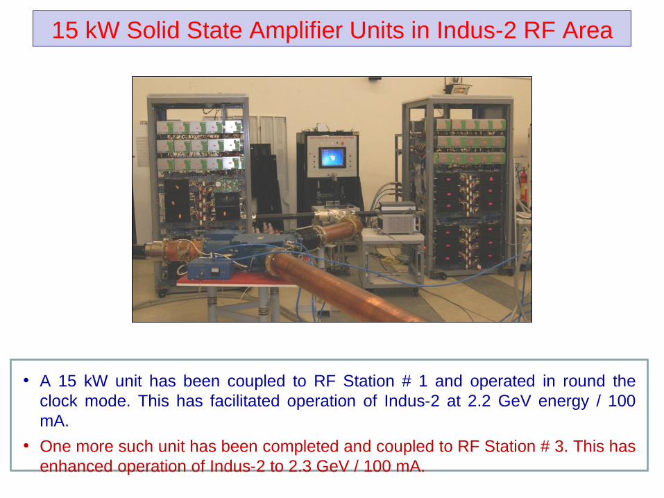
15 kW Solid State Amplifier Units in Indus-2 RF Area
• A 15 kW unit has been coupled to RF Station # 1 and operated in round the clock mode. This has facilitated operation of Indus-2 at 2.2 GeV energy / 100 mA.
• One more such unit has been completed and coupled to RF Station # 3. This has enhanced operation of Indus-2 to 2.3 GeV / 100 mA.
ADS Related Ongoing R & D ProgrammesAt BARC
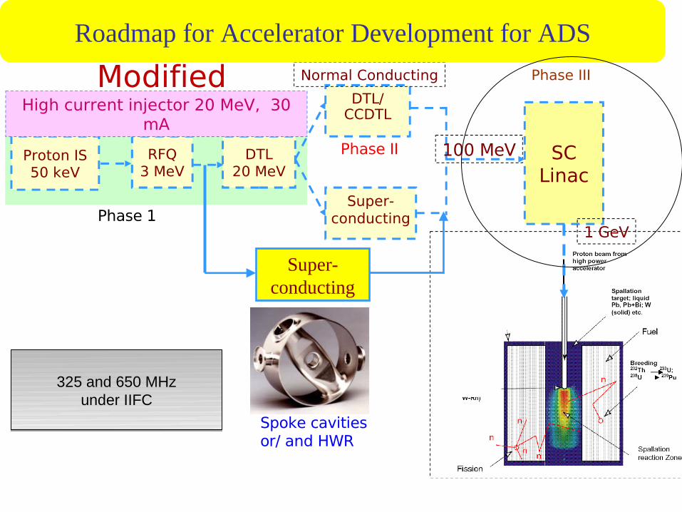
Proton IS50 keV
RFQ3 MeV
DTL20 MeV
DTL/CCDTL
Super-conducting
SC Linac
1 GeV
100 MeV
Normal Conducting
High current injector 20 MeV, 30 mA
Roadmap for Accelerator Development for ADS
Phase 1
Phase II
Phase III
Super-conducting
Spoke cavitiesor/ and HWR
Modified
325 and 650 MHzunder IIFC
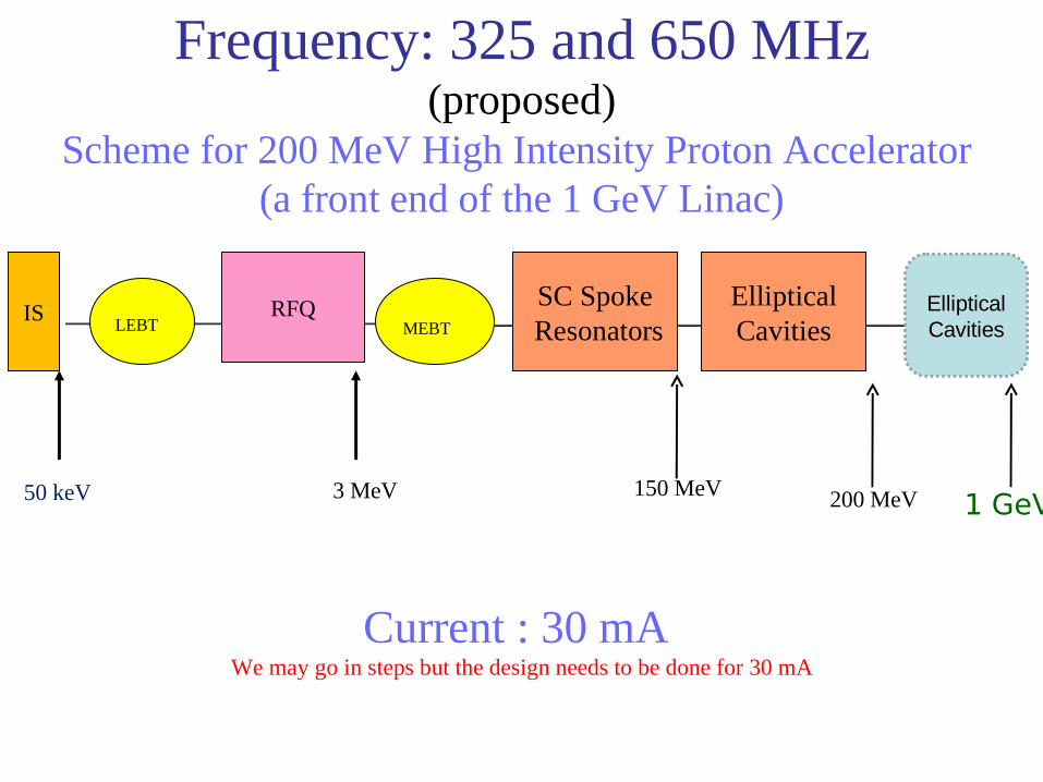
Frequency: 325 and 650 MHz(proposed)
Scheme for 200 MeV High Intensity Proton Accelerator (a front end of the 1 GeV Linac)
LEBT MEBT
EllipticalCavities
200 MeV
Current : 30 mA We may go in steps but the design needs to be done for 30 mA
1 GeV
IS RFQ SC Spoke Resonators
50 keV 3 MeV 150 MeV
Elliptical Cavities

Activities related to development of LEHIPA at BARC
Coupling of external neutrons to Critical Facility-
LEHIPA with Critical facility
PURNIMA 14 MeV Neutrons with sub-critical U core
Reactor Schemes for coupled operation
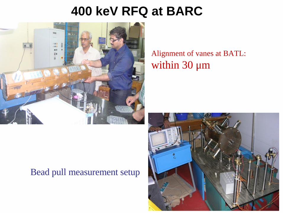
400 keV RFQ at BARC
Alignment of vanes at BATL:
within 30 μm
Bead pull measurement setup
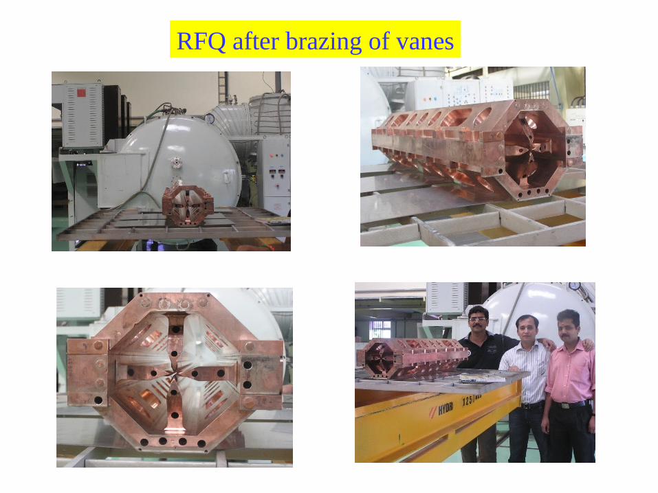
RFQ after brazing of vanes
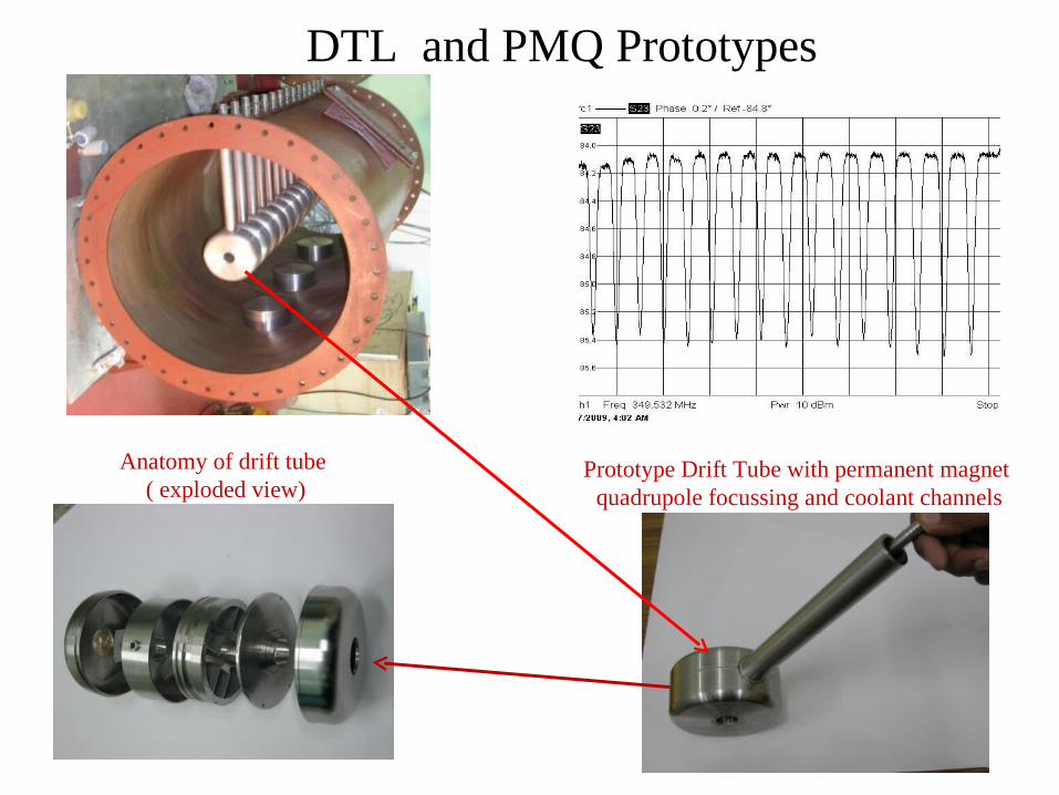
DTL and PMQ Prototypes
Prototype Drift Tube with permanent magnet quadrupole focussing and coolant channels
Anatomy of drift tube ( exploded view)
69
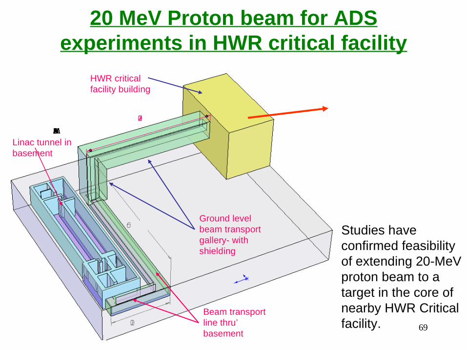
20 MeV Proton beam for ADS experiments in HWR critical facility
Linac tunnel in basement
Beam transport line thru’ basement
Ground level beam transport gallery- with shielding
HWR critical facility building
Studies have confirmed feasibility of extending 20-MeV proton beam to a target in the core of nearby HWR Critical facility.
70
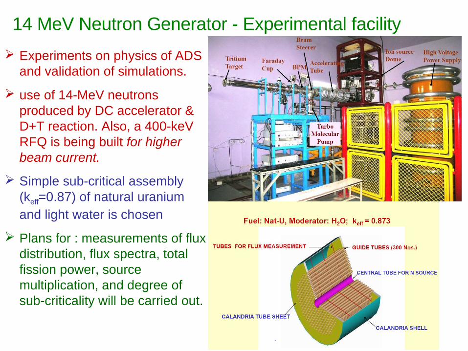
Experiments on physics of ADS and validation of simulations.
use of 14-MeV neutrons produced by DC accelerator & D+T reaction. Also, a 400-keV RFQ is being built for higher beam current.
Simple sub-critical assembly (keff=0.87) of natural uranium and light water is chosen
Plans for : measurements of flux distribution, flux spectra, total fission power, source multiplication, and degree of sub-criticality will be carried out.
14 MeV Neutron Generator - Experimental facility
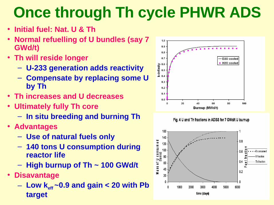
Once through Th cycle PHWR ADS• Initial fuel: Nat. U & Th• Normal refuelling of U bundles (say 7
GWd/t)• Th will reside longer
– U-233 generation adds reactivity– Compensate by replacing some U
by Th• Th increases and U decreases • Ultimately fully Th core
– In situ breeding and burning Th• Advantages
– Use of natural fuels only– 140 tons U consumption during
reactor life– High burnup of Th ~ 100 GWd/t
• Disavantage– Low keff ~0.9 and gain < 20 with Pb
target– Accelerator power ~ 30 MW for a 200 MWe ADS
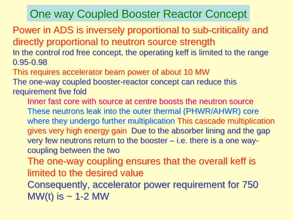
Power in ADS is inversely proportional to sub-criticality and directly proportional to neutron source strengthIn the control rod free concept, the operating keff is limited to the range 0.95-0.98 This requires accelerator beam power of about 10 MWThe one-way coupled booster-reactor concept can reduce this requirement five fold
Inner fast core with source at centre boosts the neutron source These neutrons leak into the outer thermal (PHWR/AHWR) core where they undergo further multiplication This cascade multiplication gives very high energy gain Due to the absorber lining and the gap very few neutrons return to the booster – i.e. there is a one way-coupling between the two
The one-way coupling ensures that the overall keff is limited to the desired valueConsequently, accelerator power requirement for 750 MW(t) is ~ 1-2 MW
One way Coupled Booster Reactor Concept
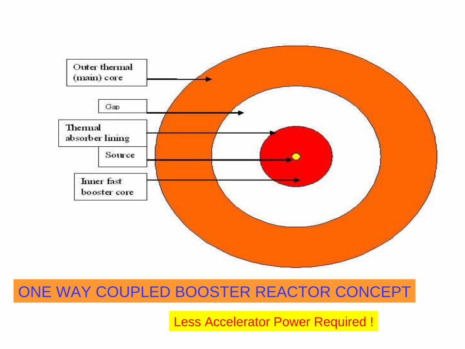
ONE WAY COUPLED BOOSTER REACTOR CONCEPT
Less Accelerator Power Required !

SUMMARY