Embed Size (px)
Citation preview

1
The Impact of Nuclear Science on Life Science
Accelerators for ADS M. Napolitano
University “Federico II” and INFN, Naples, Italy 1. Introduction The need of an in depth study of matter constituents and forces between them motivated the development of more and more powerful particle accelerators, which represent a unique tool for the experimental investigation of nuclear and sub-nuclear matter. Impressive progresses on every accelerator components have been continuously achieved since their first realization in the 1930s. Proton accelerators, with beam powers over one order of magnitude greater than the maximum power of existing accelerators, can now be designed and constructed. This allows the conception, the design and, possibly, the construction of plants, like accelerator driven systems (ADS) for waste transmutation or powerful spallation neutron sources for material science, which need proton beams of power ranging from several MW to tens of MW. The European Spallation Source (ESS) project is an example of these facilities. A reference design of ESS, based on a 1.334 GeV 5MW pulsed H- linac, was published in March 1997 [1]. A definitive plan for ESS with a possible upgrade of the beam power to 10 MW, will be ready in May 2002. Another example is the Oak Ridge spallation neutron source (SNS), which was approved in 1998 and is now in the construction phase [2]. The SNS Project foresees the realisation of a 805 MHz super-conducting linac which may accelerate a pulsed H- beam up to 1.25 GeV, with a mean power of 2.65 MW, having a peak current of 52 mA and a duty factor of 6% [3]. In the following, we will focus on the proton accelerators able to drive an ADS plant for nuclear waste transmutation. The requirements on beam structure, energy and power will be first discussed and the two possible alternatives for the accelerator, namely a linac and a cyclotron, will be introduced. A discussion on the important issues of reliability and availability will follow and, at last, the “status of the art” and the perspectives of both linacs and cyclotrons will be shortly reviewed 2. Beam requirements and options An ADS for waste transmutation requires a proton beam, possibly “continuous wave” (CW) or with a very high duty cycle, having an energy of the order of 1 GeV and a power ranging from several MW, for a low power demonstration plant, up to few tens of MW, for an industrial burner [4]. The beam energy is essentially determined by two different requirements: the neutron production rate per GeV and per proton, the energy dissipated in the input window to spallation target. The first quantity reaches the optimum values right at energy of ~1 GeV, while the second rapidly decreases with energy (when E < few GeV). The beam power is determined by the thermal power of the plant and by the chosen sub-criticality of the system. As orders of magnitudes, it can be assumed that a demonstration plant of ~100 MWth can be driven by a beam of a few MW, while an industrial plant with a thermal power of the order of 1500 MWth needs a beam power of ~30 MW.

2
At present, the most powerful proton accelerators are the LAMPF linac at LANL [5] and the PSI cyclotron [6], supplying both a ~1 MW beam, the first at 800 MeV and the second at 590 MeV. Both linac and cyclotron have been considered as possible ADS drivers. In principle, there are no fundamental obstacles for a linac to deliver beam currents up to ~100 mA at an energy of 1 GeV or more. However, 1 GeV and 10 mA may be considered as limiting values for a (multistage) cyclotron, on the basis of beam dynamics constraints. An accelerator for an ADS must satisfy the important requirement of an extremely high reliability and availability. The target, core and structures of the reactor should not be too frequently exposed to the thermal shock induced by a proton beam interruption. Moreover, the activation of the accelerator structure caused by the beam particles lost along the machine must be minimised in order to allow "hands-on" servicing and keep the downtime as low as possible. Therefore, the design and construction of an accelerator for ADS has to be done introducing additional safety margins into all accelerator components. 3. Reliability and availability Apart from any consideration on energy and current, an accelerator for an ADS must have characteristics of reliability and availability which are completely unusual in the field of nuclear and sub-nuclear physics, were accelerators have been developed and are largely used. These characteristics represent a major challenge for designing and building an accelerator for an ADS for waste transmutation and constitute the main item still requiring R&D activities. The operation of the accelerators used for nuclear and sub-nuclear physics researches has shown that sudden beam interruptions (beam trips) occur very frequently, with duration varying from very short times (of the order of milliseconds) up to relatively long times, as needed for the repair or substitution of faulty accelerator components. The reliability requirements for an ADS driver are substantially related to the number of allowed beam trips. Frequently repeated beam trips may damage the fuel bars, the target and the structure of the reactor and, also, reduce the overall availability of the plant [7]. The preliminary studies of the ADS dynamics performed so far [8], seem to suggest that short beam trips, with duration less than one second, can be tolerated by the subcritical system, due to its rather big thermal inertia. The number of allowable beam trips of duration greater than 1 second depends on the technological details of the target and the reactor. In any case, this number can be estimated of the order of hundreds per year. Long term beam interruptions affect the availability of the plant. In the perspective of industrial application, it can be estimated that the number of unexpected shutdown should not exceed ten per year [4]. For a conventional nuclear power plant this number is in the range of 1-2 per year. The above numbers are normally exceeded – in many cases by orders of magnitude - in almost all existing accelerators operating for nuclear and sub-nuclear physics [9]. This means that operating an accelerator at a high beam power and requiring, at same time, relatively few beam trips of short duration and a negligible amount of time lost for longer beam interruptions, poses new challenges in the overall design of the accelerator. However, while reliability and availability are first concerns for a nuclear plant, in nuclear and particle physics, where particle accelerators have been developed and where accelerator technology is continuously pushed ahead, priorities are usually in favour of characteristics like higher energies, higher currents, and

3
higher energy resolution. So, there should be a considerable potential for improving accelerators from the point of view of reliability and availability.
The strategy to be adopted should consider:
• very advanced control systems, based on fast electronics; they have to be able to detect at very beginning beam trips, due, for example, to the sparking of high voltage components, in order to start in a very short time actions allowing a fast recovery of the interested component. In this way, most of the short and medium term beam trips, which occur at a high frequency rate in present accelerators, could be moved in the millisecond time scale, were no damage is foreseen for fuel, target and reactor structures;
• a certain amount of over-design, which should increase the stability of accelerator components, reducing the number of beam trips, not only due to sparking of high voltage components and quenches of super-conducting devices, but also to the failure of other accelerator components, like magnets, power supplies, vacuum and cooling systems, controls;
• a careful design of the accelerator in order to allow fast interchange-ability of accelerator components that may fail during operation;
• availability of ready-to-operate replacement units;
• careful planning of components tests and severe acceptance criteria.
The modular structure of a linac should allow an easy implementation of the above concepts. It should also be possible to envisage a “spare-on-line” strategy using a higher number of modules than strictly necessary: in case of failure, a component may be switched-off and the following part of the accelerator rapidly re-tuned. The compactness and the reduced number of components of a cyclotron allow following only partially the above strategy. However, a different approach to reliability and availability could be to drive the ADS by several independent accelerators; in this case, the reduced dimension and the relatively low cost of a single accelerator could play in favour of cyclotrons. As it concerns the “hands-on” servicing and maintenance, a linac guarantees very low losses, even for very intense beams. On the contrary, beam losses during acceleration and, in particular, at extraction may result an extremely critical item for a cyclotron, due to its weak focussing and the extremely tight packing of the orbits at high energy. 4. Linear accelerator: status and perspectives The design of a high power proton linac benefits of the impressive progresses made in the last decades in the field of super-conducting elliptical RF cavities [10]. Most of recent progresses have been motivated by the construction of the big accelerators like CEBAF at JLAB [11], LEP2 at CERN [12, 13], TRISTAN and KEKB at KEK [14], and, for niobium-bulk cavities, especially by the TTF-TESLA project at DESY [15].

4
Even though elliptical cavities were developed mainly for relativistic particles, R&D work going-on from several years has demonstrated the possibility to extend the technology of SC elliptical cavities to the acceleration of protons of relatively low velocity, possibly down to β∼0.5. The scheme of a high power proton linac generally considered consists of three different sections [3, 16, 17, 18, 19]: • the injector, which deliver a proton beam with energy of the order of 5 MeV; • a low energy section, that brings protons at an energy of the order of 100-200 MeV; • a high energy section, that accelerates protons up to the final energy by SC elliptical RF
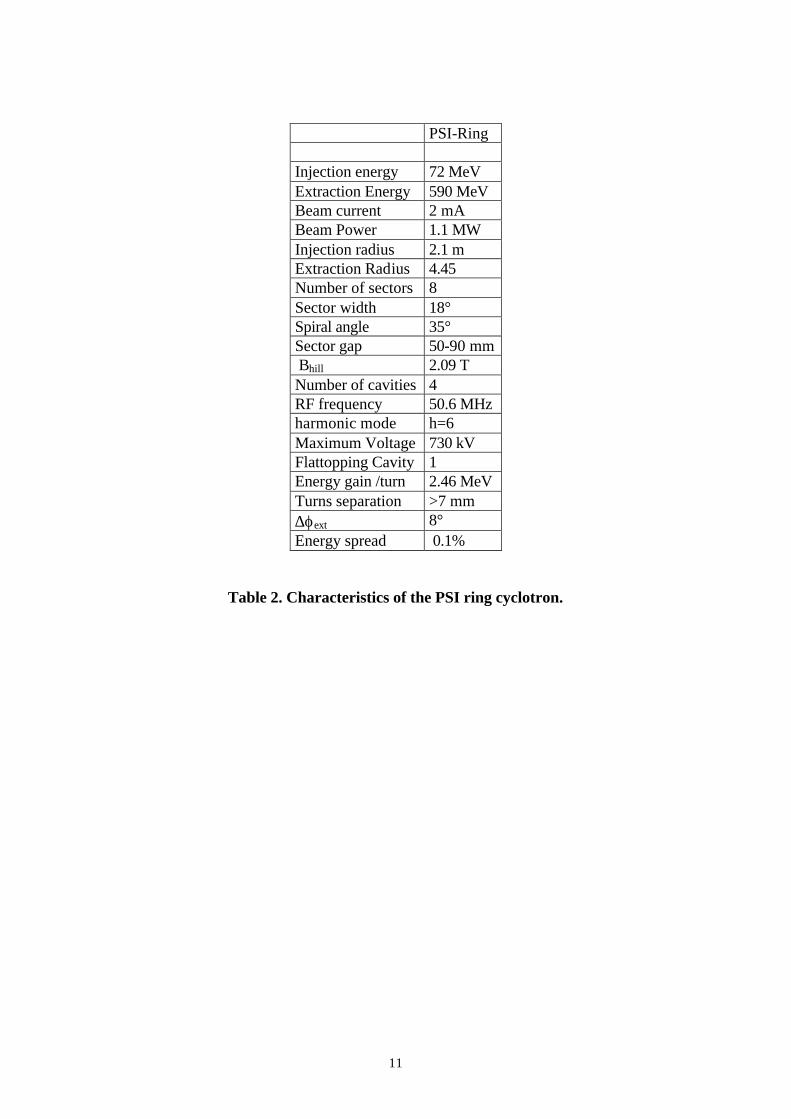
cavities. The injector consists essentially of a source and a radio-frequency quadrupole (RFQ). The first, normally, is a microwave source with an accelerating voltage lower than 0.1 MV. The RFQ is made of normal-conducting copper-bulk structures brazed together. Due to its capacity of accelerating and focussing at the same time, the RFQ is the best tool for initial beam formation, when disruptive space-charge effects are dominant. LEDA (Low-Energy Demonstrator Accelerator), at Los Alamos, has demonstrated the feasibility of injectors able to produce CW proton beams of 100 mA and 6.7 MeV [20]. The 8 m-long, 350 MHz RFQ accelerates a dc, 75 keV, 110 mA proton beam from LEDA source with ∼94% transmission and a measured normalised emittance of ∼0.25 π mm mrad. Similar injectors are in construction in France and Italy. At Saclay the IPHI project [21] aims at producing a CW proton beam of 100 mA and 10 MeV. The general layout of IPHI is reported in Figure 1. An ECR source, delivering a 100 mA proton beam at 95 keV, feeds a normal conducting RFQ, able to provide a 500 kW, 5 MeV CW beam; a drift tube linac (DTL) tank accelerates the beam up to 11 MeV. The source (SILHI) has been built since a few years. Currents up to 100 mA are reached in a routine basis with a normalised emittance below 0.2 π mm mrad. A long run of 103 hours uninterrupted operation, with only one “beam trip”, demonstrated an availability of 99.96% [22, 23]. In Italy, a lower current (30 mA) injector [16] has been designed in the frame of the TRASCO project [24]. The proton source (TRIPS) provides 35 mA dc proton beam, with a normalised emittance below 0.2 π mm mrad, at an operating voltage of 80 kV. The source, based on the off-resonance microwave discharge, is a modified version of SILHI [25]. Presently, TRIPS is under test. The 7 m long 352 MHz RFQ [26] will accelerate the beam provided by TRIPS up to 5 MeV, with a transmission of 96%. The beam loading of 0.15 MW, less than one fourth of LEDA RFQ, allowed a “relaxed” RFQ design. The inter-vane voltage has been kept constant along the structure and gives a “reasonably” low power dissipation density of 850 W per cm of structure length. A single klystron will be used to feed the resonator. The design of the high-energy section of the accelerator is based in all designs on the technology of super-conducting RF elliptical cavities. The main advantage of these cavities is their capacity of transferring to the beam nearly all the RF power. This efficiency, approximately equal to 1, has to be compared with that, roughly half, of ordinary normal-conducting copper cavities. This characteristics is of paramount importance in order to accelerate CW beams with currents from few mA to 100 mA or more. The operation costs of the accelerator are considerably lowered and the technological problems, related to the requirement of carrying away the huge power
5
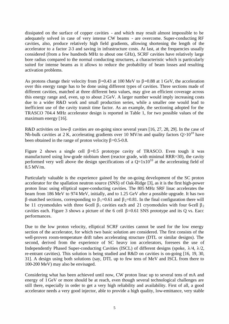
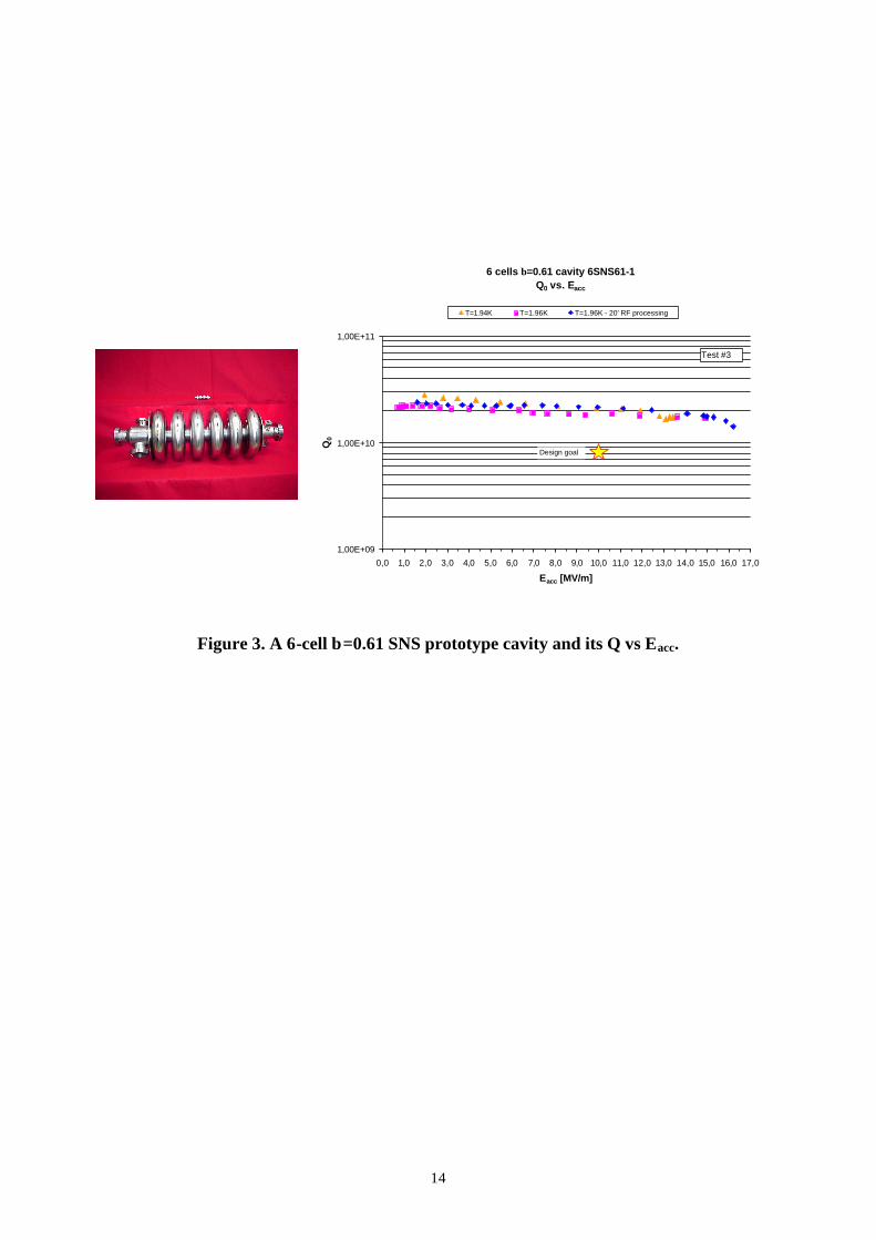
dissipated on the surface of copper cavities - and which may result almost impossible to be adequately solved in case of very intense CW beams - are overcome. Super-conducting RF cavities, also, produce relatively high field gradients, allowing shortening the length of the accelerator to a factor 2-3 and saving in infrastructure costs. At last, at the frequencies usually considered (from a few hundreds MHz to about one GHz), SCRF cavities have relatively large bore radius compared to the normal conducting structures, a characteristic which is particularly suited for intense beams as it allows to reduce the probability of beam losses and resulting activation problems. As protons change their velocity from β=0.43 at 100 MeV to β=0.88 at 1 GeV, the acceleration over this energy range has to be done using different types of cavities. Three sections made of different cavities, matched at three different beta values, may give an efficient coverage across this energy range and, even, up to about 2 GeV. A larger number would imply increasing costs due to a wider R&D work and small production series, while a smaller one would lead to inefficient use of the cavity transit time factor. As an example, the sectioning adopted for the TRASCO 704.4 MHz accelerator design is reported in Table 1, for two possible values of the maximum energy [16]. R&D activities on low-β cavities are on-going since several years [16, 27, 28, 29]. In the case of Nb-bulk cavities at 2 K, accelerating gradients over 10 MV/m and quality factors Q>1010 have been obtained in the range of proton velocity β=0.5-0.8. Figure 2 shows a single cell β=0.5 prototype cavity of TRASCO. Even tough it was manufactured using low-grade niobium sheet (reactor grade, with minimal RRR=30), the cavity performed very well above the design specifications of a Q=1x10¹⁰ at the accelerating field of 8.5 MV/m. Particularly valuable is the experience gained by the on-going development of the SC proton accelerator for the spallation neutron source (SNS) of Oak-Ridge [3], as it is the first high-power proton linac using elliptical super-conducting cavities. The 805 MHz SRF linac accelerates the beam from 186 MeV to 974 MeV, initially, and to 1.25 GeV after a possible upgrade. It has two β-matched sections, corresponding to β1=0.61 and β2=0.81. In the final configuration there will be 11 cryomodules with three 6-cell β1 cavities each and 21 cryomodules with four 6-cell β2 cavities each. Figure 3 shows a picture of the 6 cell β=0.61 SNS prototype and its Q vs. Eacc performances. Due to the low proton velocity, elliptical SCRF cavities cannot be used for the low energy section of the accelerator, for which two basic solution are considered. The first consists of the well-proven room-temperature drift tubes accelerating structure (DTL or similar designs). The second, derived from the experience of SC heavy ion accelerators, foresees the use of Independently Phased Super-conducting Cavities (ISCL) of different designs (spoke, λ/4, λ/2, re-entrant cavities). This solution is being studied and R&D on cavities is on-going [16, 19, 30, 31]. A design using both solutions (say, DTL up to few tens of MeV and ISCL from there to 100-200 MeV) may also be envisaged. Considering what has been achieved until now, CW proton linac up to several tens of mA and energy of 1 GeV or more should be at reach, even though several technological challenges are still there, especially in order to get a very high reliability and availability. First of all, a good accelerator needs a very good injector, able to provide a high quality, low-emittance, very stable
6
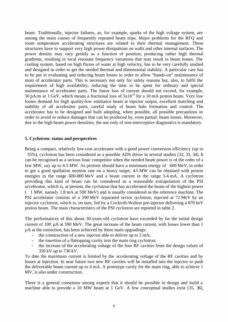
beam. Traditionally, injector failures, as, for example, sparks of the high voltage system, are among the main causes of frequently repeated beam trips. Major problems for the RFQ and room temperature accelerating structures are related to their thermal management. These structures have to support very high power dissipations on walls and other internal surfaces. The power density may vary greatly as a function of position, producing rather high thermal gradients, resulting in local resonant frequency variations that may result in beam losses. The cooling system, based on high fluxes of water at high velocity, has to be very carefully studied and designed in order to get the needed thermal and dimensional stability. A particular care has to be put in evaluating and reducing beam losses in order to allow “hands-on” maintenance of most of accelerator parts. This is necessary not only for safety reasons but, also, to fulfil the requirement of high availability, reducing the time to be spent for ordinary and special maintenance of accelerator parts. The linear loss of current should not exceed, for example, 50 pA/m at 1 GeV, which means a fractional loss of 5x10⁻⁹ for a 10 mA proton beam. Very low losses demand for high quality-low emittance beam at injector output, excellent matching and stability of all accelerator parts, careful study of beam halo formation and control. The accelerator has to be designed and built adopting, when possible, all possible precautions in order to avoid or reduce damages that can be produced by, even partial, beam losses. Moreover, due to the high beam power densities, the use only of non-interceptive diagnostics is mandatory. 5. Cyclotron: status and perspectives Being a compact, relatively low-cost accelerator with a good power conversion efficiency (up to ∼35%), cyclotron has been considered as a possible ADS driver in several studies [32, 33, 34]. It can be recognised as a serious linac competitor when the needed beam power is of the order of a few MW, say up to 4-5 MW. As protons should have a minimum energy of ∼600 MeV, in order to get a good spallation neutron rate on a heavy target, 4-5 MW can be obtained with proton energies in the range 600-800 MeV and a beam current in the range 5-6 mA. A cyclotron providing this kind of beam can be considered as a reasonable extrapolation of the PSI accelerator, which is, at present, the cyclotron that has accelerated the beam of the highest power (∼ 1 MW, namely 1.8 mA at 590 MeV) and is usually considered as the reference machine. The PSI accelerator consists of a 590 MeV separated sector cyclotron, injected at 72 MeV by an injector cyclotron, which is, on turn, fed by a Cockroft-Walton pre-injector delivering a 870 keV proton beam. The main characteristics of the PSI cyclotron are reported in table 2. The performances of this about 30-years-old cyclotron have exceeded by far the initial design current of 100 µA at 590 MeV. The great increase of the beam current, with losses lower than 1 µA at the extraction, has been achieved by three main upgradings:
- the construction of a new injector able to deliver up to 2 mA; - the insertion of a flattopping cavity into the main ring cyclotron; - the increase of the accelerating voltage of the four RF cavities from the design values of
350 kV up to 730 kV. To date the maximum current is limited by the accelerating voltage of the RF cavities and by losses at injection. In near future two new RF cavities will be installed into the injector to push the deliverable beam current up to 4 mA. A prototype cavity for the main ring, able to achieve 1 MV, is also under construction. There is a general consensus among experts that it should be possible to design and build a machine able to provide a 10 MW beam at 1 GeV. A few conceptual studies exist [35, 36],

7
based on few cascading stages of which, at least, the last one should be a separated sector cyclotron. A general scheme foresees three different stages and is similar to the PSI scheme: • a pre-injector consisting of an intense source coupled to a compact cyclotron or a Cockroft-
Walton accelerator or an RFQ; beam energy can range from less than 1 MeV up to few MeV • a separated sector intermediate cyclotron, with at least four sectors, that brings protons up to
roughly 100 MeV; • a final separated sector cyclotron, which accelerates protons up to 1 GeV and should contain
a number of sectors of the order of 12. The beam extraction is one of the most critical point of a cyclotron. For a 1 GeV, 10 MW beam a very high efficient beam extraction is needed to minimise beam losses that could damage the apparatus and activate the components, preventing hands-on servicing and maintenance. Single-turn extraction is mandatory in order to get high efficiency; this requires well-separated orbits for which a high-energy gain per turn and a well-defined narrow beam are necessary. The first is obtained using very high accelerating potentials. As it concerns the second, the dimensions of a high energy, high intensity beam are mainly determined by the energy spread, which, hence, has to be low in order to get a narrow beam. Then, due to the lack of any longitudinal focussing, the beam has to be bunched with a relatively low phase acceptance (10°-20° RF) and has to reach extraction after a relatively low number of turns and this, still, requires high accelerating potentials. High potentials and great dimensions make the accelerating cavities a very critical part, together with extraction, of the design and construction of the cyclotron. Even though a 1 GeV, 10 mA cyclotron can be seen as a reachable goal, RF, injection and extraction systems need intense studies and R&D. Concerning extraction, in order to reduce beam losses, acceleration of H2
+, instead of protons, and extraction by stripping has been proposed [37]. Extraction by stripping does not require well-separated orbits. The energy gain per turn may be lower, allowing lower accelerating potentials and lower power losses in RF cavities. Preliminary studies of a super-conducting ring cyclotron, able to accelerate a H2
+ beam to 1 GeV/amu, have been published [38]. Only preliminary conceptual studies have been done, until now, on high energy, high current cyclotrons. The extrapolation of one order of magnitude of the achieved highest cyclotron beam power could not be “at a reach” in the same way as it is for a linac, for which the intrinsic characteristics and intense R&D activity, on-going from many years, make feasible a several tens MW beam accelerator.

8
6. References 1) I. S. K. Gardner et al., “Status of the European Spallation Source Design Study”, Proc.
PAC1997, Vancouver, Canada, 1997. See, also, http;//www.ess-europe.de/ 2) See http://www.sns.gov/ 3) J. Stovall et al., “Superconducting Linac for the SNS”, Proc. of the XX Int. Linac
Conference, Monterey, CA, USA, August 2000 4) The European Technical Working Group, “An European Roadmap for Developing
Accelerator Driven Systems (ADS) for Nuclear Waste Transmutation”, April 2001 5) A. Jason, “Linac-Driven Spallation-Neutron Source”, Proc of PAC 95, 6) See http://www1.psi.ch/www_gfa_hn/abe/ringcyc.html 7) M. Salvatores, this issue 8) Proc. of the Second OECD/NEA Workshop on Utilisation and Reliability of High Power
Proton Accelerators, Aix-en-Provence, France, Nov. 1999 (to be published) 9) See, for example: C. M. Piaszczyk, “Operational Experiences at Existing Accelerator
Facilities”, Proc. of the First OECD/NEA Workshop on Utilisation and Reliability of High Power Proton Accelerators, Mito, Japan, Oct. 1998
10) H. Safa, “Progress and Trends in SRCF Cavities for Future Accelerators”, Proc. of EPAC 2000, Vienna, Austria, June 2000
11) See http://www.jlab.org/ 12) LEP Design Report, Vol. II, LEP2, CERN 1996 13) D. Boussard and E. Chiaveri, “The LEP Super-conducting RF System: Characteristics and
Operational Experience”, Proc. of the First OECD/NEA Workshop on Utilisation and Reliability of High Power Proton Accelerators, Mito, Japan, Oct. 1998
14) See http://www.kek.jp 15) TESLA, Technical Design Report, Part II, DESY 2001-011, March 2001 16) The TRASCO_AC Group, “Status of High Current Proton Accelerator for the TRASCO
Program”, INFN/TC-00/23, http://wwwsis.lnf.infn.it/pub/INFN-TC-00-23.pdf 17) The SPL Study Group: ”Conceptual Design of the SPL, a High-Power Super-conducting
H- Linac at CERN”, CERN 2000-012, Dec. 2000 18) H. Safa, “A Super-Conducting Proton Linac for Waste Transmutation”, Proc. of the 9th
Workshop on RF Super-conductivity”, Santa Fe, NM, USA, Nov. 1999 19) A Roadmap for Developing Acceleration Transmutation of Wastes (ATW) Technology:
Accelerator Technology, LA-UR 99-3235, Oct. 1999 20) H. Vernon Smith et al., “Commissioning Results from the Low Energy Demonstration
Accelerator (LEDA) Radio-Frequency Quadrupole (RFQ)”, Proc. of EPAC 2000, Vienna, Austria, June 2000
21) J-M. Lagniel et al., “IPHI, the Saclay High-Intensity Proton Injector Project”, Proc. PAC1997, Vancouver, Canada, 1997
22) R. Gobin et al., “Reliability of High Power Proton Source SILHI”, Proc. of the Second OECD/NEA Workshop on Utilisation and Reliability of High Power Proton Accelerators, Aix-en-Provence, France, Nov. 1999 (to be published)
23) P-Y. Beauvais et al., “Status Report on the Saclay High-Intensity Proton Injector Project (IPHI), Proc. EPAC 2000, Vienna, Austria, June 2000
24) http://trasco.lnl.infn.it 25) G. Ciavola et al., “Installation of TRIPS at INFN-LNS”, Proc. EPAC 2000, Vienna,
Austria, June 2000 26) A. Pisent et al., “TRASCO RFQ”, Proc. of the XX Int. Linac Conference, Monterey, CA,
USA, August 2000

9
27) J. Kusano et al., “Devepopment of Superconducting Single Cell Cavity for a Proton Linac in the Neutron Science Project at JAERI”, Proc. EPAC 1998, Stockholm, Sweden, June 1998
28) E. Chiaveri et al., “Production and Test of the Prototype β=0.85 Five Cell Cavity for the TRASCO Project”, Proc. of the 9th Workshop on RF Super-conductivity”, Santa Fe, NM, USA, Nov. 1999
29) J. L. Biarrotte et al., “704 MHz Superconducting Cavities for a High Intensity Proton Accelerator”, Proc. of the 9th Workshop on RF Super-conductivity”, Santa Fe, NM, USA, Nov. 1999
30) A. Pisent et al., “TRASCO 100 MeV High Ijntensity Proton Linac”, Proc. EPAC 2000, Vienna, Austria, June 2000
31) A. Facco et al., “A Superconductive, Low Beta Single Gap Cavity for a High Intensity Proton Linac”, Proc. of the XX Int. Linac Conference, Monterey, CA, USA, August 2000
32) C. Rubbia et al., “Conceptual Design of a Fast Neutron Operated High Power Energy Amplifier”, Cern/AT/95-44 (ET), Sept. 1995
33) Ansaldo, “Energy Amplifier Demonstration Facility Reference Configuration”, EA B0.00 1 200, Jan. 1999
34) Myrra Project,http://www.sckcen.be/research/reactorsafety/fuel/myrrha/myrra_home.html. 35) N. Fietier et al., “A Three Stage Cycloton for Driving the Energy Amplifier”,
CERN/AT/95-03 (ET), 1995 and Mandrillon et al., “Important Design Issues of a High Efficiency Cyclotron Complex to Drive the Energy Amplifier”, Proc. of EPAC 1996, Barcelona, Spain, 1996
36) T. Stammbach et al., “The feasibility of high power cyclotrons”, Nucl. Instr. And Meth. In Phys. Res. B113, 1 (1996)
37) L. Calabretta and D. Rifuggiato, “Superconducting Cyclotrons for Acceleration of H2+“,
Proc. of the First OECD/NEA Workshop on Utilisation and Reliability of High Power Proton Accelerators, Mito, Japan, Oct. 1998
38) L. Calabretta et al., “A Super-conducting Ring Cyclotron to Deliver High Intensity Proton Beams”, Proc. EPAC 2000, Vienna, Austria, June 2000

10
Section 3 Section 1 Section 2 1 GeV 2 GeV
Section βs 0.50 0.68 0.86 Section Length [m] 84 124.2 110.5 297.5 Input Energy [MeV] 85 200 500 Focussing Period [m] 4.2 4.6 8.5 # Focussing Periods 20 27 13 35 Max Gain/Cavity [MeV] 3.3 6.0 11.4 Max Eacc [MV/m] 8.5 10.2 12.3 # Cells/Cavity 5 5 6 # Cavities/Section 40 54 52 140 # Cavities/Cryomodule 2 2 4 # Cryomodule/Klystron 1 1 1 Max RF/Coupler [kW] 66 120 228
Table 1. Sectioning adopted for the TRASCO 704.4 MHz super-conducting linac.
11
PSI-Ring Injection energy 72 MeV Extraction Energy 590 MeV Beam current 2 mA Beam Power 1.1 MW Injection radius 2.1 m Extraction Radius 4.45 Number of sectors 8 Sector width 18° Spiral angle 35° Sector gap 50-90 mm Bhill 2.09 T Number of cavities 4 RF frequency 50.6 MHz harmonic mode h=6 Maximum Voltage 730 kV Flattopping Cavity 1 Energy gain /turn 2.46 MeV Turns separation >7 mm ∆ϕext 8° Energy spread 0.1%
Table 2. Characteristics of the PSI ring cyclotron.
12
Figure 1. Layout of the Saclay high intensity proton injector (IPHI).

13
0 1 2 3 4 5 6 7 8 9 10 11 12
0.6
0.8
1
2
4
6
8
10
TRASCO Specifications Q=1 x 10¹⁰ @ 8.5 MV/m
Bpeak
[mT]
Q [1010]
Eacc
[MV/m]
0 5 10 15 20 25 30 35 40 45 50 55 60 65
Figure 2. A single cell β=0.5 prototype cavity of TRASCO and its Q vs Eacc.
14
6 cells β=0.61 cavity 6SNS61-1Q0 vs. Eacc
1,00E+09
1,00E+10
1,00E+11
0,0 1,0 2,0 3,0 4,0 5,0 6,0 7,0 8,0 9,0 10,0 11,0 12,0 13,0 14,0 15,0 16,0 17,0
Eacc [MV/m]
Q0
T=1.94K T=1.96K T=1.96K - 20' RF processing
Test #3
Design goal
Figure 3. A 6-cell β=0.61 SNS prototype cavity and its Q vs Eacc.