Embed Size (px)
Citation preview
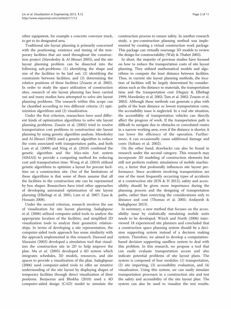
Lin et al. Visualization in Engineering 2013, 1:12http://www.viejournal.com/content/1/1/12
RESEARCH ARTICLE Open Access
Accessibility evaluation system for site layoutplanning – a tractor trailer exampleJacob Je-Chian Lin, Chi-En Yang, Wei-Han Hung and Shih-Chung Kang*
Abstract
Background: Accessibility is a critical issue in site planning. A good accessibility plan can avoid possible conflictsinvolving equipment and allows for smooth transportation during the entire project. It can also ensure thatsufficient space is available so that all onsite equipment, such as trucks, cranes and excavators can be safelyoperated. In current practice, the evaluation of accessibility is done manually, relying heavily on the experienceof the construction planners. However, the evaluation needs to deal with temporal and spatial informationsimultaneously, which make the manual evaluations very challenging.
Methods: This research develops a sandbox environment for construction planners. As tractor-trailers are usuallycritical in accessibility evaluations, the simulation specifically focuses on these two-section vehicles. Four major stepswere involved: Step 1: deriving a generic tractor-trailer mathematical model allowing real-time, physics-basedcomputer simulation; Step 2: digitalizing a 2D site plan to the 3D virtual environment; Step 3: developing evaluationmethods for accessibility, considering both safety and operability; Step 4: visualizing the evaluation results. Weimplemented these four steps using Microsoft XNA (a game platform) and Nvidia PhysX (a game engine). Anexample case is presented which uses the sandbox environment to evaluate the accessibility of a construction site.
Results: From the case study, we found that realistic visualizations and simulations provide solid references forconstruction planners. They are able to identify potential accessibility problems and unsafe situations in thesandbox environment and avoid them early on in the design and planning stages.
Conclusion: This paper proposed an innovative approach for evaluating accessibility during pre-construction sitelayout planning. It can present an intuitive and easily understood visualization result which clearly indicated theunsafe parts of the site layout plan.
Keywords: Accessibility; Site layout; Trailer truck; Physics-based simulation; Game engine
BackgroundAccessibility is one of the most important considerationsin site layout planning. The routes of a construction siteneed to be designed to ensure smooth delivery of mate-rials, safe machine operation and relatively easy relocationof large objects on site. Site planning directly influencesthe construction progress and often impacts cost if thereare any unforeseen conflicts (Su et al. 2012).Although accessibility appears to be an intuitively
important issue in construction site layout planning, ithas not been well-researched thus far. In practice, theevaluation of accessibility is still done manually, relying
* Correspondence: [email protected] Engineering Group, Department of Civil Engineering,National Taiwan University, 188, Sec. 3, HsinHai Rd, Taipei 10668, Taiwan
© 2013 Lin et al.; licensee Springer. This is an oAttribution License (http://creativecommons.orin any medium, provided the original work is p
heavily on the experience of the construction planners(Tam & Tong 2003; Elbeltagi et al. 2004; Li et al. 2009).Daily meetings are held to deal with accessibility prob-lems in which the engineers discuss transportation pathsand the location of heavy equipment and temporaryfacilities to ensure that none of the various processeswill be in conflict with one another. Without an intuitivetool to evaluate the accessibility of the site, engineersevaluate the space they need by considering qualitativepositions (Akinci et al. 2002), which could easily lead toaccessibility problems. Conflicts are usually caused by anincorrect assessment of the space occupied by equipmentand facilities. Sometimes newly constructed elements/parts may need to be demolished to create a passage for
pen access article distributed under the terms of the Creative Commonsg/licenses/by/2.0), which permits unrestricted use, distribution, and reproductionroperly cited.
Lin et al. Visualization in Engineering 2013, 1:12 Page 2 of 11http://www.viejournal.com/content/1/1/12
other equipment, for example a concrete conveyor truck,to get to its designated area.Traditional site layout planning is primarily concerned
with the positioning, existence and timing of the tem-porary facilities that are used throughout the construc-tion project (Mawdesley & Al-Jibouri 2003), and the sitelayout planning problem can be dissected into thefollowing sub-problems: (1) identifying the shape andsize of the facilities to be laid out; (2) identifying theconstraints between facilities; and (3) determining therelative positions of these facilities (Zouein et al. 2002).In order to study the space utilization of constructionsites, research of site layout planning has been carriedout and many studies have attempted to solve site layoutplanning problems. The research within this scope canbe classified according to two different criteria: (1) opti-mization algorithms and (2) visualization.Under the first criterion, researchers have used differ-
ent kinds of optimization algorithms to solve site layoutplanning problems. Zouein et al. (2002) tried to resolvetransportation cost problems in construction site layoutplanning by using genetic algorithm analysis. Mawdesleyand Al-Jibouri (2003) used a genetic algorithm to reducethe costs associated with transportation paths, and bothLam et al. (2009) and Ning et al. (2010) combined thegenetic algorithm and the Max-min Ant system(MMAS) to provide a computing method for reducingcost and transportation time. Wong et al. (2010) utilizedgenetic algorithms to optimize a layout for precast facil-ities on a construction site. One of the limitations ofthese algorithms is that some of them assume that allthe facilities in the construction site can be representedby box shapes. Researchers have tried other approachesof developing automated optimization of site layoutplanning (Elbeltagi et al. 2001; Lam et al. 2007; Easa &Hossain 2008).Under the second criterion, research involves the use
of visualization for site layout planning. Sadeghpouret al. (2006) utilized computer-aided tools to analyze theappropriate location of the facilities, and simplified 2Dvisualization tools to analyze their geometric relation-ships. In terms of developing a site representation, thecomputer-aided tools approach has some similarity withthe approach implemented in this research. Dawood andMarasini (2003) developed a simulation tool that visual-izes the construction site in 2D to help improve theplan. Ma et al. (2005) developed a 4D system whichintegrates schedules, 3D models, resources, and sitespaces to provide a visualization of the plan. Sadeghpour(2006) used computer-aided tools to offer an intuitiveunderstanding of the site layout by displaying shapes oftemporary facilities through direct visualization of theirpositions. Benjaoran and Bhokha (2010) used a 4Dcomputer-aided design (CAD) model to simulate the
construction process to ensure safety. In another researchstudy, a pre-construction planning method was imple-mented by creating a virtual construction work package.This package can virtually rearrange 3D models to reviewthe design for constructability (Waly & Thabet 2003).In short, the majority of previous studies have focused
on how to reduce the transportation costs of site layoutplanning. They utilized mathematical models and algo-rithms to compute the least distance between facilities.Thus, in current site layout planning methods, the loca-tion of facilities will be largely determined by consider-ations such as the distance to materials, the transportationtime and the transportation cost (Hegazy & Elbeltagi1999; Mawdesley et al. 2002; Tam et al. 2002; Zouein et al.2002). Although these methods can generate a plan withpaths of the least distance or lowest transportation costs,the accessibility issue is neglected. In a real site situation,the accessibility of transportation vehicles can directlyaffect the progress of work. If the transportation path isdifficult to navigate due to obstacles or convoluted routesin a narrow working area, even if the distance is shorter, itcan lower the efficiency of the operation. Further-more, it can occasionally cause additional damage andcosts (Soltani et al. 2002).On the other hand, drawbacks can also be found in
research under the second category. This research mayincorporate 3D modeling of construction elements butstill not perform realistic simulations of mobile machin-ery, a factor that profoundly influences site layout per-formance. Since accidents involving transportation areone of the most frequently occurring types of accidentsat a construction site (IOS & H 2012), safety and acces-sibility should be given more importance during theplanning process and the designing of transportationpaths, rather than restricting the considerations only todistance and cost (Thomas et al. 2005; Andayesh &Sadeghpour 2013).In summary, a new method that focuses on the acces-
sibility issue by realistically simulating mobile unitsneeds to be developed. Winch and North (2006) inter-viewed 18 experienced site planners and concluded thata construction space planning system should be a deci-sion supporting system instead of a decision makingsystem. Therefore, we aimed to develop a computation-based decision supporting sandbox system to deal withthis problem. In this research, we propose a tool thatcan easily evaluate transportation access and alsoindicate potential problems of site layout plans. Thesystem is composed of four modules: (1) transportation,(2) site importing, (3) accessibility evaluation, and (4)visualization. Using this system, we can easily simulatetransportation processes in a construction site and testthe safety and accessibility of the site layout plan. Thesystem can also be used to visualize the test results.
Lin et al. Visualization in Engineering 2013, 1:12 Page 3 of 11http://www.viejournal.com/content/1/1/12
Engineers can therefore easily identify the unsafe partsof a site and mitigate potential accessibility problems.
Research goalsIn this research, we developed an accessibility evaluationsystem for site layout planning. Because tractor-trailersare usually critical in accessibility evaluations, we havespecifically focused the simulation on these two-sectionvehicles. The system can facilitate the achievement ofthe following goals:
1. The simulation of transportation in an interactive,realistic virtual environment. From this, users candirectly simulate transportation process to identifypotential safety and accessibility problems undervarious situations and different site layout plans.
2. The development of an evaluation method for siteaccessibility. Via the proposed system, users can testtheir planned site layout and evaluate its accessibilityand safety. After evaluation, the proposed systemcan support a visualized output of the evaluatedresult to help engineers understand the unsafe areasof the site layout, and therefore being able to workout a lower cost, safer, and improved plan.
3. The importing of the map of the construction siteand the building up of the virtual environment ofthe construction site in a fast and efficient way.
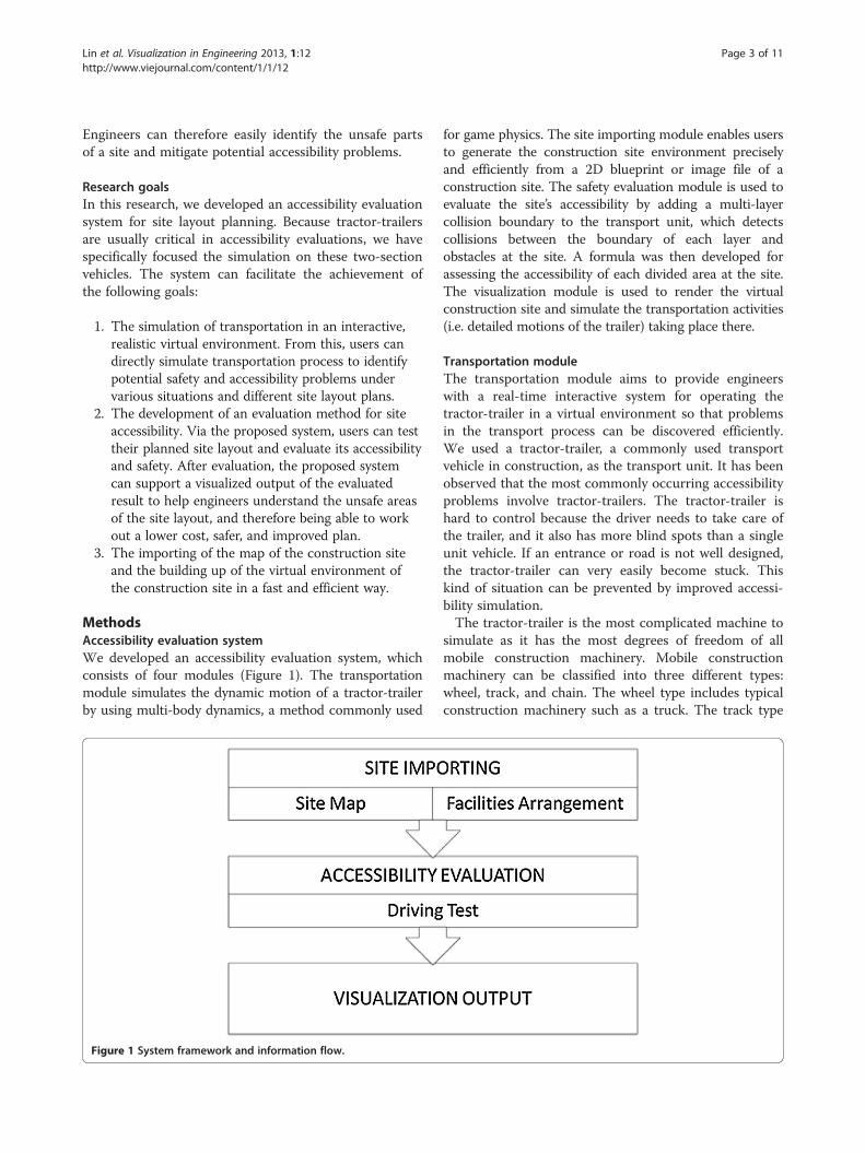
MethodsAccessibility evaluation systemWe developed an accessibility evaluation system, whichconsists of four modules (Figure 1). The transportationmodule simulates the dynamic motion of a tractor-trailerby using multi-body dynamics, a method commonly used
Figure 1 System framework and information flow.
for game physics. The site importing module enables usersto generate the construction site environment preciselyand efficiently from a 2D blueprint or image file of aconstruction site. The safety evaluation module is used toevaluate the site’s accessibility by adding a multi-layercollision boundary to the transport unit, which detectscollisions between the boundary of each layer andobstacles at the site. A formula was then developed forassessing the accessibility of each divided area at the site.The visualization module is used to render the virtualconstruction site and simulate the transportation activities(i.e. detailed motions of the trailer) taking place there.
Transportation moduleThe transportation module aims to provide engineerswith a real-time interactive system for operating thetractor-trailer in a virtual environment so that problemsin the transport process can be discovered efficiently.We used a tractor-trailer, a commonly used transportvehicle in construction, as the transport unit. It has beenobserved that the most commonly occurring accessibilityproblems involve tractor-trailers. The tractor-trailer ishard to control because the driver needs to take care ofthe trailer, and it also has more blind spots than a singleunit vehicle. If an entrance or road is not well designed,the tractor-trailer can very easily become stuck. Thiskind of situation can be prevented by improved accessi-bility simulation.The tractor-trailer is the most complicated machine to
simulate as it has the most degrees of freedom of allmobile construction machinery. Mobile constructionmachinery can be classified into three different types:wheel, track, and chain. The wheel type includes typicalconstruction machinery such as a truck. The track type
Lin et al. Visualization in Engineering 2013, 1:12 Page 4 of 11http://www.viejournal.com/content/1/1/12
refers more to heavy construction machinery such as anexcavator. The chain type consists of multiple rigidbodies and connections such as a tractor-trailer. Thechain type is the most complicated because its motionhas the most degrees of freedom. Once the accessibilitymethod for simulating the tractor-trailer is established,the user can easily apply it to other kinds of mobileconstruction machinery. A tractor-trailer is composed ofmultiple rigid bodies and connections. Mathematicalequations can be used to represent the relationshipsbetween the connections of rigid bodies, which arecontrolled by the rules of physics. We used the conceptof multi-body dynamics, which are commonly used forsimulating and modeling the dynamic motions of articu-lated mechanisms or equipment (Hung & Kang 2009).We also provided a mathematical model to comparewith the developed model to verify its feasibility.
Tractor-trailer model using multi-body dynamicsMulti-body dynamics is mainly used for computingphysical feedback between multiple bodies in mutualcontact with each other or connected to each other byjoints (Erleben 2005). The simulation of multi-bodydynamics is generally composed of rigid body dynamicsand constraints. By solving the equations of motion(which are used to describe the dynamic behavior ofmulti-body dynamics), the simulation can calculate thebehavior of a multi-body during each time integration(Hung & Kang 2009).In this study, the rigid bodies in the tractor-trailer are
called actors (for example, the bodies that steer thewheels of a car). The type of Joint determines the motionbetween a pair of rigid bodies within the entire multi-body. The basic joint used in this paper is the revolutejoint, which attaches two actors by a hinge-like struc-ture. It only has one degree of freedom of rotation sothat the two actors can only rotate on one axis (Hung &Kang 2009).A tractor-trailer can be separated into two main parts:
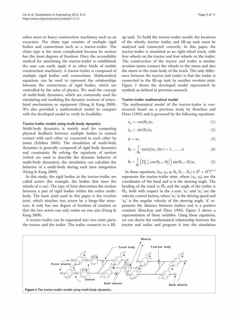
the tractor and the trailer. The trailer connects to a fill-
Figure 2 The tractor-trailer model using multi-body dynamics.
up tank. To build the tractor-trailer model, the locationsof the wheels, tractor, trailer, and fill-up tank must beanalyzed and connected correctly. In this paper, thetractor-trailer is simulated as an eight-wheel truck, withfour wheels on the tractor and four wheels on the trailer.The construction of the tractor and trailer is similar:revolute joints connect the wheels to the steers and alsothe steers to the main body of the truck. The only differ-ence between the tractor and trailer is that the trailer isconnected to the fill-up tank by another revolute joint.Figure 2 shows the developed model represented bysymbols as defined in previous research.
Tractor-trailer mathematical modelThe mathematical model of the tractor-trailer is con-structed based on a previous study by Rouchon andFliess (1993) and is governed by the following equations:
x0 ¼ cos θ0ð Þu1 ð1Þy0 ¼ sin θ0ð Þu1 ð2Þ
φ ¼ u2 ð3Þ
θ0¼ 1
d0tan φð Þu1; for i ¼ 1;……; n ð4Þ
θi¼ 1
di∏i−1
j¼1 cos θj−1−θj� �� �
sin θi−1−θið Þu1 ð5Þ
In these equations, (x0, y0, φ, θ0, θ1… θn) ∈ R2 × (S1)n+2
represents the tractor-trailer state, where (x0, y0) are thecoordinates of the head and φ is the steering angle. Theheading of the truck is ϴ0 and the angle of the trailer isϴ1, both with respect to the x-axis. ‘u1’ and ‘u2’ are thevelocity control factors, where ‘u1’ is the driving speed and‘u2’ is the angular velocity of the steering angle. ‘d’ re-presents the distance between trailers and is a positiveconstant (Rouchon and Fliess 1993). Figure 3 shows arepresentation of these variables. Using these equations,we can derive the mathematical relationship between thetractor and trailer and program it into the simulation
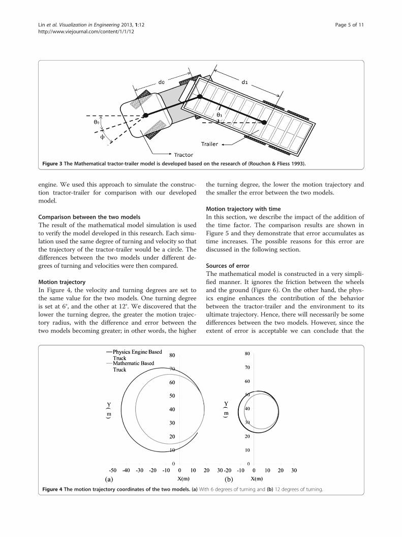
Figure 3 The Mathematical tractor-trailer model is developed based on the research of (Rouchon & Fliess 1993).
Lin et al. Visualization in Engineering 2013, 1:12 Page 5 of 11http://www.viejournal.com/content/1/1/12
engine. We used this approach to simulate the construc-tion tractor-trailer for comparison with our developedmodel.
Comparison between the two modelsThe result of the mathematical model simulation is usedto verify the model developed in this research. Each simu-lation used the same degree of turning and velocity so thatthe trajectory of the tractor-trailer would be a circle. Thedifferences between the two models under different de-grees of turning and velocities were then compared.
Motion trajectoryIn Figure 4, the velocity and turning degrees are set tothe same value for the two models. One turning degreeis set at 6°, and the other at 12°. We discovered that thelower the turning degree, the greater the motion trajec-tory radius, with the difference and error between thetwo models becoming greater; in other words, the higher
Figure 4 The motion trajectory coordinates of the two models. (a) Wi
the turning degree, the lower the motion trajectory andthe smaller the error between the two models.
Motion trajectory with timeIn this section, we describe the impact of the addition ofthe time factor. The comparison results are shown inFigure 5 and they demonstrate that error accumulates astime increases. The possible reasons for this error arediscussed in the following section.
Sources of errorThe mathematical model is constructed in a very simpli-fied manner. It ignores the friction between the wheelsand the ground (Figure 6). On the other hand, the phys-ics engine enhances the contribution of the behaviorbetween the tractor-trailer and the environment to itsultimate trajectory. Hence, there will necessarily be somedifferences between the two models. However, since theextent of error is acceptable we can conclude that the
th 6 degrees of turning and (b) 12 degrees of turning.
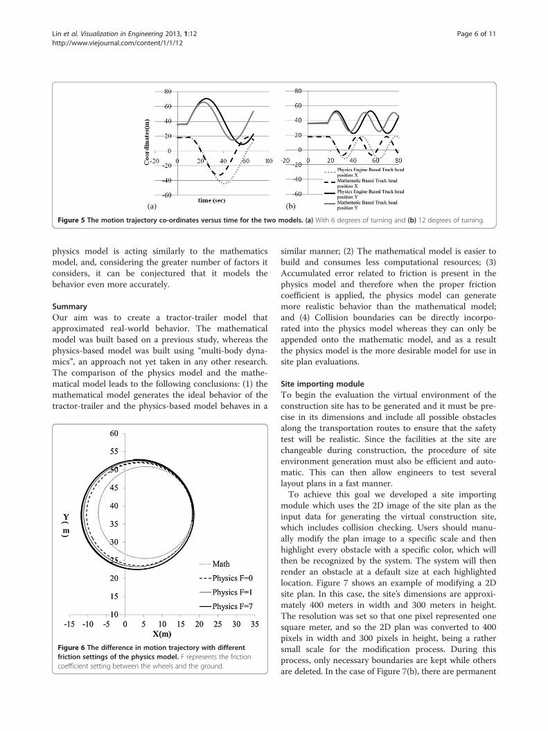
Figure 5 The motion trajectory co-ordinates versus time for the two models. (a) With 6 degrees of turning and (b) 12 degrees of turning.
Lin et al. Visualization in Engineering 2013, 1:12 Page 6 of 11http://www.viejournal.com/content/1/1/12
physics model is acting similarly to the mathematicsmodel, and, considering the greater number of factors itconsiders, it can be conjectured that it models thebehavior even more accurately.
SummaryOur aim was to create a tractor-trailer model thatapproximated real-world behavior. The mathematicalmodel was built based on a previous study, whereas thephysics-based model was built using “multi-body dyna-mics”, an approach not yet taken in any other research.The comparison of the physics model and the mathe-matical model leads to the following conclusions: (1) themathematical model generates the ideal behavior of thetractor-trailer and the physics-based model behaves in a
Figure 6 The difference in motion trajectory with differentfriction settings of the physics model. F represents the frictioncoefficient setting between the wheels and the ground.
similar manner; (2) The mathematical model is easier tobuild and consumes less computational resources; (3)Accumulated error related to friction is present in thephysics model and therefore when the proper frictioncoefficient is applied, the physics model can generatemore realistic behavior than the mathematical model;and (4) Collision boundaries can be directly incorpo-rated into the physics model whereas they can only beappended onto the mathematic model, and as a resultthe physics model is the more desirable model for use insite plan evaluations.
Site importing moduleTo begin the evaluation the virtual environment of theconstruction site has to be generated and it must be pre-cise in its dimensions and include all possible obstaclesalong the transportation routes to ensure that the safetytest will be realistic. Since the facilities at the site arechangeable during construction, the procedure of siteenvironment generation must also be efficient and auto-matic. This can then allow engineers to test severallayout plans in a fast manner.To achieve this goal we developed a site importing
module which uses the 2D image of the site plan as theinput data for generating the virtual construction site,which includes collision checking. Users should manu-ally modify the plan image to a specific scale and thenhighlight every obstacle with a specific color, which willthen be recognized by the system. The system will thenrender an obstacle at a default size at each highlightedlocation. Figure 7 shows an example of modifying a 2Dsite plan. In this case, the site’s dimensions are approxi-mately 400 meters in width and 300 meters in height.The resolution was set so that one pixel represented onesquare meter, and so the 2D plan was converted to 400pixels in width and 300 pixels in height, being a rathersmall scale for the modification process. During thisprocess, only necessary boundaries are kept while othersare deleted. In the case of Figure 7(b), there are permanent
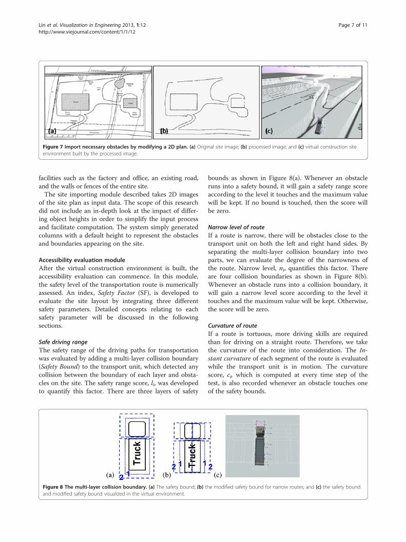
Figure 7 Import necessary obstacles by modifying a 2D plan. (a) Original site image; (b) processed image; and (c) virtual construction siteenvironment built by the processed image.
Lin et al. Visualization in Engineering 2013, 1:12 Page 7 of 11http://www.viejournal.com/content/1/1/12
facilities such as the factory and office, an existing road,and the walls or fences of the entire site.The site importing module described takes 2D images
of the site plan as input data. The scope of this researchdid not include an in-depth look at the impact of differ-ing object heights in order to simplify the input processand facilitate computation. The system simply generatedcolumns with a default height to represent the obstaclesand boundaries appearing on the site.
Accessibility evaluation moduleAfter the virtual construction environment is built, theaccessibility evaluation can commence. In this module,the safety level of the transportation route is numericallyassessed. An index, Safety Factor (SF), is developed toevaluate the site layout by integrating three differentsafety parameters. Detailed concepts relating to eachsafety parameter will be discussed in the followingsections.
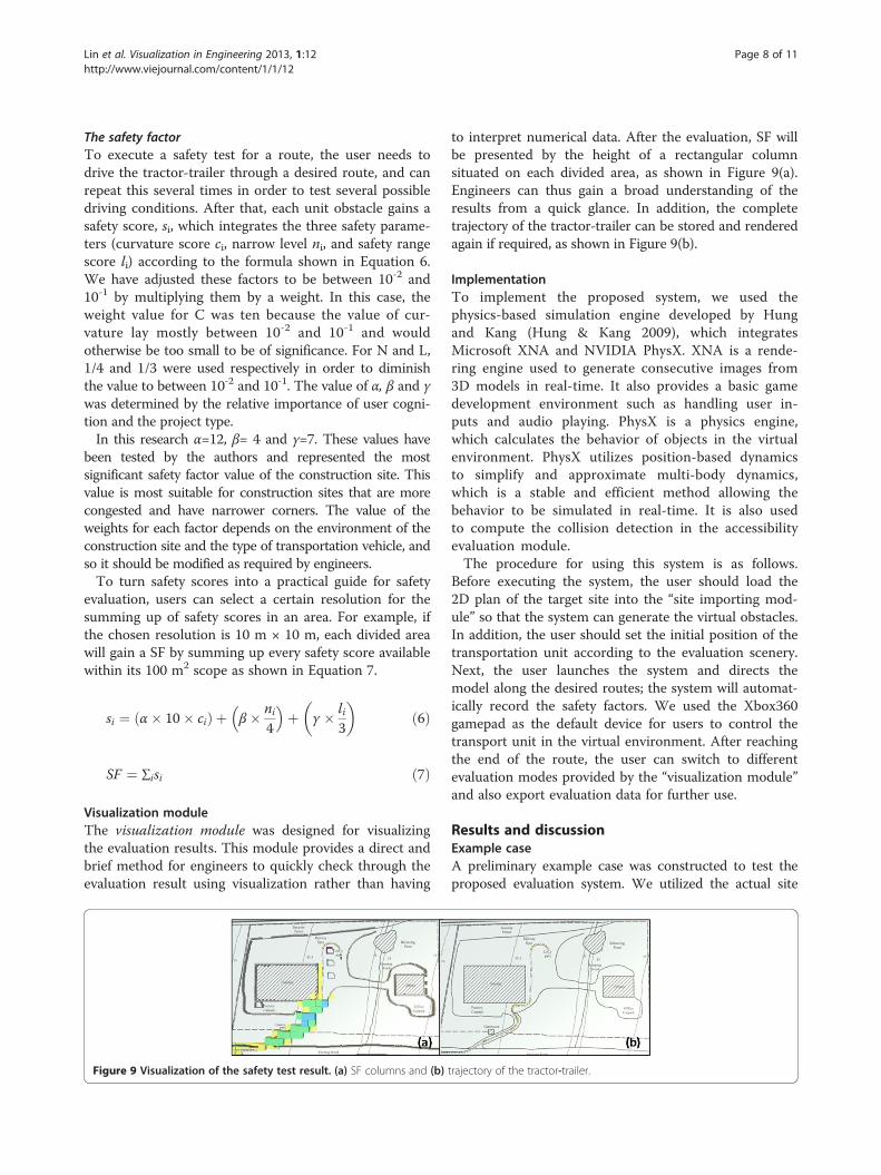
Safe driving rangeThe safety range of the driving paths for transportationwas evaluated by adding a multi-layer collision boundary(Safety Bound) to the transport unit, which detected anycollision between the boundary of each layer and obsta-cles on the site. The safety range score, li, was developedto quantify this factor. There are three layers of safety
Figure 8 The multi-layer collision boundary. (a) The safety bound; (b) tand modified safety bound visualized in the virtual environment.
bounds as shown in Figure 8(a). Whenever an obstacleruns into a safety bound, it will gain a safety range scoreaccording to the level it touches and the maximum valuewill be kept. If no bound is touched, then the score willbe zero.
Narrow level of routeIf a route is narrow, there will be obstacles close to thetransport unit on both the left and right hand sides. Byseparating the multi-layer collision boundary into twoparts, we can evaluate the degree of the narrowness ofthe route. Narrow level, ni, quantifies this factor. Thereare four collision boundaries as shown in Figure 8(b).Whenever an obstacle runs into a collision boundary, itwill gain a narrow level score according to the level ittouches and the maximum value will be kept. Otherwise,the score will be zero.
Curvature of routeIf a route is tortuous, more driving skills are requiredthan for driving on a straight route. Therefore, we takethe curvature of the route into consideration. The In-stant curvature of each segment of the route is evaluatedwhile the transport unit is in motion. The curvaturescore, ci, which is computed at every time step of thetest, is also recorded whenever an obstacle touches oneof the safety bounds.
he modified safety bound for narrow routes; and (c) the safety bound
Lin et al. Visualization in Engineering 2013, 1:12 Page 8 of 11http://www.viejournal.com/content/1/1/12
The safety factorTo execute a safety test for a route, the user needs todrive the tractor-trailer through a desired route, and canrepeat this several times in order to test several possibledriving conditions. After that, each unit obstacle gains asafety score, si, which integrates the three safety parame-ters (curvature score ci, narrow level ni, and safety rangescore li) according to the formula shown in Equation 6.We have adjusted these factors to be between 10-2 and10-1 by multiplying them by a weight. In this case, theweight value for C was ten because the value of cur-vature lay mostly between 10-2 and 10-1 and wouldotherwise be too small to be of significance. For N and L,1/4 and 1/3 were used respectively in order to diminishthe value to between 10-2 and 10-1. The value of α, β and γwas determined by the relative importance of user cogni-tion and the project type.In this research α=12, β= 4 and γ=7. These values have
been tested by the authors and represented the mostsignificant safety factor value of the construction site. Thisvalue is most suitable for construction sites that are morecongested and have narrower corners. The value of theweights for each factor depends on the environment of theconstruction site and the type of transportation vehicle, andso it should be modified as required by engineers.To turn safety scores into a practical guide for safety
evaluation, users can select a certain resolution for thesumming up of safety scores in an area. For example, ifthe chosen resolution is 10 m × 10 m, each divided areawill gain a SF by summing up every safety score availablewithin its 100 m2 scope as shown in Equation 7.
si ¼ α� 10� cið Þ þ β� ni4
� �þ γ � li
3
� �ð6Þ
SF ¼ ∑isi ð7Þ
Visualization moduleThe visualization module was designed for visualizingthe evaluation results. This module provides a direct andbrief method for engineers to quickly check through theevaluation result using visualization rather than having
Figure 9 Visualization of the safety test result. (a) SF columns and (b)
to interpret numerical data. After the evaluation, SF willbe presented by the height of a rectangular columnsituated on each divided area, as shown in Figure 9(a).Engineers can thus gain a broad understanding of theresults from a quick glance. In addition, the completetrajectory of the tractor-trailer can be stored and renderedagain if required, as shown in Figure 9(b).
ImplementationTo implement the proposed system, we used thephysics-based simulation engine developed by Hungand Kang (Hung & Kang 2009), which integratesMicrosoft XNA and NVIDIA PhysX. XNA is a rende-ring engine used to generate consecutive images from3D models in real-time. It also provides a basic gamedevelopment environment such as handling user in-puts and audio playing. PhysX is a physics engine,which calculates the behavior of objects in the virtualenvironment. PhysX utilizes position-based dynamicsto simplify and approximate multi-body dynamics,which is a stable and efficient method allowing thebehavior to be simulated in real-time. It is also usedto compute the collision detection in the accessibilityevaluation module.The procedure for using this system is as follows.
Before executing the system, the user should load the2D plan of the target site into the “site importing mod-ule” so that the system can generate the virtual obstacles.In addition, the user should set the initial position of thetransportation unit according to the evaluation scenery.Next, the user launches the system and directs themodel along the desired routes; the system will automat-ically record the safety factors. We used the Xbox360gamepad as the default device for users to control thetransport unit in the virtual environment. After reachingthe end of the route, the user can switch to differentevaluation modes provided by the “visualization module”and also export evaluation data for further use.
Results and discussionExample caseA preliminary example case was constructed to test theproposed evaluation system. We utilized the actual site
trajectory of the tractor-trailer.
Lin et al. Visualization in Engineering 2013, 1:12 Page 9 of 11http://www.viejournal.com/content/1/1/12
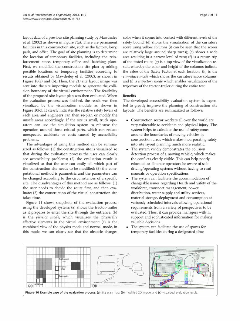
layout data of a previous site planning study by Mawdesleyet al. (2002) as shown in Figure 7(a). There are permanentfacilities in this construction site, such as the factory, lorry,park, and office. The goal of site planning is to determinethe location of temporary facilities, including the rein-forcement store, temporary office and batching plant.First, we modified the construction site plan by addingpossible locations of temporary facilities according toresults obtained by Mawdesley et al. (2002), as shown inFigure 10(a) and (b). Then, the 2D site layout image wassent into the site importing module to generate the colli-sion boundary of the virtual environment. The feasibilityof the proposed site layout plan was then evaluated. Whenthe evaluation process was finished, the result was thenvisualized by the visualization module as shown inFigure 10(c). It clearly indicates the relative safety levels ofeach area and engineers can then re-plan or modify theunsafe areas accordingly. If the site is small, truck ope-rators can use the simulation system to rehearse theoperation around those critical parts, which can reduceunexpected accidents or costs caused by accessibilityproblems.The advantages of using this method can be summa-
rized as follows: (1) the construction site is visualized sothat during the evaluation process the user can clearlysee accessibility problems; (2) the evaluation result isvisualized so that the user can easily tell which part ofthe construction site needs to be modified; (3) the com-putational method is parametric and the parameters canbe changed according to the circumstances of a specificsite. The disadvantages of this method are as follows: (1)the user needs to decide the route first, and then eva-luate; (2) the construction of the virtual construction sitetakes time.Figure 11 shows snapshots of the evaluation process
using the developed system: (a) shows the tractor-traileras it prepares to enter the site through the entrance; (b)is the physics mode, which visualizes the physicallyeffective elements in the virtual environment; (c) is thecombined view of the physics mode and normal mode, inthis mode, we can clearly see that the obstacle changes
Figure 10 Example case of the evaluation process. (a) Site plan map; (b
color when it comes into contact with different levels of thesafety bound; (d) shows the visualization of the curvaturescore using yellow columns (it can be seen that the scoresare relatively large around sharp turns); (e) shows a widearea resulting in a narrow level of zero; (f) is a return tripof the tested route; (g) is a top view of the visualization re-sult, whereby the color and height of the columns indicatethe value of the Safety Factor at each location; (h) is thecurvature mode which shows the curvature score columns;and (i) is trajectory mode which enables visualization of thetrajectory of the tractor-trailer during the entire test.
BenefitsThe developed accessibility evaluation system is expec-ted to greatly improve the planning of construction sitelayouts. The benefits are summarized as follows:
� Construction sector workers all over the world arevery vulnerable to accidents and physical injury. Thesystem helps to calculate the use of safety zonesaround the boundaries of moving vehicles inconstruction areas which makes incorporating safetyinto site layout planning much more realistic.
� The system vividly demonstrates the collisiondetection process of a moving vehicle, which makesthe conflicts clearly visible. This can help poorlyeducated or illiterate operators be aware of safedriving/operating systems without having to readmanuals or operation specifications.
� The system can facilitate the accommodation ofchangeable issues regarding Health and Safety of theworkforce, transport management, powerdistribution, water supply and utility services,material storage, deployment and consumption atvariously scheduled intervals allowing operationalrequirements from a variety of perspectives to beevaluated. Thus, it can provide managers with ITsupport and sophisticated information for makingvaluable decisions.
� The system can facilitate the use of spaces fortemporary facilities during a designated time
) modified 2D image; and (c) visualized evaluation result.

Figure 11 Snapshots of the evaluation process in the developed system. (a)-(c) The basic three viewing modes of the system; (d)-(f)visualized narrow level, safety range score and curvature score; and (g)-(i) three visualization modes of the evaluation result.
Lin et al. Visualization in Engineering 2013, 1:12 Page 10 of 11http://www.viejournal.com/content/1/1/12
window to help relieve congestion of operationsat site.
� The optimum level of exposure for a movingtruck can be recognized through color detection.Therefore, the optimal position of the objectcan be established for strategic areas.
� Analyzing the closeness of objects, it helps inoptimizing the positioning and the durationof the activities of certain expensive machineoperations. The closeness of the objects canbe analyzed by an evaluation of the Safe DrivingRange safety parameter.
� The system can help to identify problems regardingthe changing of site layouts at different phases ofconstruction. Thus, it can help analyze and controlthe sequence and priority of different phases of workto obtain a high cost-time productivity. Duringdifferent phases, the user can try to evaluate theaccessibility of the site layout.
� It helps to identify the minimum space required tosupport specific construction operations inrestricted space or congested areas, thus improvingthe welfare of workers and pedestrians. Because theaccessibility of the tractor-trailer can affect the spaceof other operations, the user can understand therequired space of operations by the accessibilityevaluation of the site.
� The modeled method helps engineers progress froman “experience-based” to a “computation–based”accessibility evaluation, which will make it easier toidentify potential problems.
ConclusionsThis paper proposed an innovative approach for evaluatingaccessibility during pre-construction site layout planning. A3D simulation platform was developed for the verificationof the feasibility of a site layout plan. In this system, a phy-sics engine was used to capture the motion and reaction ofthe objects in the environment in order to approximate realworld conditions. To allow work on different planningcases to be carried out efficiently, a site importing modulewas designed. The visualization module features the advan-tage of virtual reality, providing engineers with an easy wayto check evaluation results and improve current site plan-ning proposals. This paper described an example case usingthe proposed system to evaluate the safety and accessibilityof an actual site layout plan. The evaluation result pre-sented an intuitive and easily understood visualizationwhich clearly indicated the unsafe parts of the site layoutplan. The example case results show that the proposed sys-tem has the potential to reduce the costs caused by trans-portation accessibility problems.The same modeling method used for the tractor-trailer
can be applied to different kinds of construction machinery
Lin et al. Visualization in Engineering 2013, 1:12 Page 11 of 11http://www.viejournal.com/content/1/1/12
and future research will be directed towards this end sothat the developed accessibility evaluation method can beused. The major limitation of this research is that themethod has only been tested by one example case, and al-though it is a relatively complicated scenario, the methodmust be applied to more construction sites to validate itseffectiveness more conclusively. Furthermore, by applyingthe method to more cases, the user can also identify moresafety factors that can be included in the safety score. Thesystem provides a realistic interactive environment forusers in which they may simulate any possible route of thetractor-trailer. In future work, the route could be decidedautomatically by applying a motion planning algorithm.
Competing interestThe authors declare that they have no competing interests.
Authors’ contributionJCL and CEY co-developed the accessibility evaluation system andcontributed evenly to the whole study and manuscript writing. WHHdeveloped the simulation environment implementing multi-body dynamicsin his previous research, and was included as the basis of this study. SCK wasthe adviser and proof-read the article. All authors read and approved thefinal manuscript.
Received: 6 May 2013 Accepted: 4 November 2013Published: 9 December 2013
ReferencesAkinci, B, Fischer, M, et al. (2002). Automated generation of work spaces required
by construction activities. Journal of Construction Engineering andManagement-Asce, 128(4), 306–315.
Andayesh, M, & Sadeghpour, F. (2013). Dynamic site layout planning throughminimization of total potential energy. Automation in Construction,31, 92–102.
Benjaoran, V, & Bhokha, S. (2010). An integrated safety management withconstruction management using 4D CAD model. Safety Science, 48(3), 395–403.
Dawood, N, & Marasini, R. (2003). Visualisation of a stockyard layout simulator“SimStock”: a case study in precast concrete products industry. Automation inConstruction, 12(2), 113–122.
Easa, S, & Hossain, K. (2008). New Mathematical Optimization Model forConstruction Site Layout. Journal of Construction Engineering andManagement, 134(8), 653–662.
Elbeltagi, E, Hegazy, T, et al. (2004). Dynamic Layout of Construction TemporaryFacilities Considering Safety. Journal of Construction Engineering andManagement, 130(4), 534–541.
Elbeltagi, E, Hegazy, T, et al. (2001). Schedule-dependent evolution of site layoutplanning. Construction Management and Economics, 19(7), 689–697.
Erleben, K. (2005). Physics-based animation. Hingham: Mass., Charles River Media.Hegazy, T, & Elbeltagi, E. (1999). EvoSite: Evolution-based model for site layout
planning. Journal of Computing in Civil Engineering, 13(3), 198–206.Hung, WH, & Kang, SC. (2009). Physics-Based Crane Model for the Simulation of
Cooperative Erections (p. 11). Sydney: 9th International Conference onConstruction Applications of Virtual Reality.
IOS&H. (2012). Construction Industry Accidents Knowledge Platform.http://www.iosh.gov.tw/CIAKP/Statistics2.aspx.
Lam, KC, Ning, X, et al. (2009). Conjoining MMAS to GA to Solve Construction SiteLayout Planning Problem. Journal of Construction Engineering andManagement-Asce, 135(10), 1049–1057.
Lam, KC, Ning, X, et al. (2007). The application of the ant colony optimizationalgorithm to the construction site layout planning problem. ConstructionManagement and Economics, 25(4), 359–374.
Li, H, Chan, N, et al. (2009). Optimizing construction planning schedules byvirtual prototyping enabled resource analysis. Automation in Construction,18(7), 912–918.
Ma, Z, Shen, Q, et al. (2005). Application of 4D for dynamic site layout andmanagement of construction projects. Automation in Construction,14(3), 369–381.
Mawdesley, MJ, & Al-Jibouri, SH. (2003). Proposed genetic algorithms forconstruction site layout. Engineering Applications of Artificial Intelligence,16(5–6), 501–509.
Mawdesley, MJ, Al-jibouri, SH, et al. (2002). Genetic algorithms for constructionsite layout in project planning. Journal of Construction Engineering andManagement, 128(5), 418–426.
Ning, X, Lam, KC, et al. (2010). Dynamic construction site layout planning usingmax-min ant system. Automation in Construction, 19(1), 55–65.
Rouchon, P, & Fliess, M. (1993). Flatness, motion planning and trailer systems(pp. 2700–2705). San Antonio, Texas, U.S.A: Proceedings of the 32nd IEEEConference on Decision and Control.
Sadeghpour, F, Moselhi, O, et al. (2006). Computer-aided site layout planning.Journal of Construction Engineering and Management-Asce, 132(2), 143–151.
Soltani, AR, Tawfik, H, et al. (2002). Path planning in construction sites:performance evaluation of the Dijkstra, A∗, and GA search algorithms.Advanced Engineering Informatics, 16(4), 291–303.
Su, X, Andoh, AR, et al. (2012). GIS-based dynamic construction site materiallayout evaluation for building renovation projects. Automation inConstruction, 27, 40–49.
Tam, CM, & Tong, TKL. (2003). GA-ANN model for optimizing the locations oftower crane and supply points for high-rise public housing construction.Construction Management and Economics, 21(3), 257–266.
Tam, CM, Tong, TKL, et al. (2002). Site layout planning using nonstructural fuzzydecision support system. Journal of Construction Engineering andManagement, 128(3), 220–231.
Thomas, HR, Riley, DR, et al. (2005). Fundamental principles of site materialmanagement. Journal of Construction Engineering and Management,131(7), 808–815.
Waly, AF, & Thabet, WY. (2003). A Virtual Construction Environment forpreconstruction planning. Automation in Construction, 12(2), 139–154.
Winch, G, & North, S. (2006). Critical Space Analysis. Journal of ConstructionEngineering and Management, 132(5), 473–481.
Wong, CK, Fung, IWH, et al. (2010). Comparison of Using Mixed-IntegerProgramming and Genetic Algorithms for Construction Site FacilityLayout Planning. Journal of Construction Engineering and Management-Asce,136(10), 1116–1128.
Zouein, PP, Harmanani, H, et al. (2002). Genetic algorithm for solving site layoutproblem with unequal-size and constrained facilities. Journal of Computingin Civil Engineering, 16(2), 143–151.
doi:10.1186/2213-7459-1-12Cite this article as: Lin et al.: Accessibility evaluation system for sitelayout planning – a tractor trailer example. Visualization in Engineering2013 1:12.
Submit your manuscript to a journal and benefi t from:
7 Convenient online submission
7 Rigorous peer review
7 Immediate publication on acceptance
7 Open access: articles freely available online
7 High visibility within the fi eld
7 Retaining the copyright to your article
Submit your next manuscript at 7 springeropen.com